US11150307B2 - Apparatus and method for diagnosing battery - Google Patents
Apparatus and method for diagnosing battery Download PDFInfo
- Publication number
- US11150307B2 US11150307B2 US16/643,907 US201916643907A US11150307B2 US 11150307 B2 US11150307 B2 US 11150307B2 US 201916643907 A US201916643907 A US 201916643907A US 11150307 B2 US11150307 B2 US 11150307B2
- Authority
- US
- United States
- Prior art keywords
- differential coefficient
- battery
- increase
- preset reference
- soc
- Prior art date
- Legal status (The legal status is an assumption and is not a legal conclusion. Google has not performed a legal analysis and makes no representation as to the accuracy of the status listed.)
- Active, expires
Links
Images


Classifications
-
- G—PHYSICS
- G01—MEASURING; TESTING
- G01R—MEASURING ELECTRIC VARIABLES; MEASURING MAGNETIC VARIABLES
- G01R31/00—Arrangements for testing electric properties; Arrangements for locating electric faults; Arrangements for electrical testing characterised by what is being tested not provided for elsewhere
- G01R31/36—Arrangements for testing, measuring or monitoring the electrical condition of accumulators or electric batteries, e.g. capacity or state of charge [SoC]
- G01R31/389—Measuring internal impedance, internal conductance or related variables
-
- G—PHYSICS
- G01—MEASURING; TESTING
- G01R—MEASURING ELECTRIC VARIABLES; MEASURING MAGNETIC VARIABLES
- G01R31/00—Arrangements for testing electric properties; Arrangements for locating electric faults; Arrangements for electrical testing characterised by what is being tested not provided for elsewhere
- G01R31/36—Arrangements for testing, measuring or monitoring the electrical condition of accumulators or electric batteries, e.g. capacity or state of charge [SoC]
- G01R31/3644—Constructional arrangements
- G01R31/3648—Constructional arrangements comprising digital calculation means, e.g. for performing an algorithm
-
- G—PHYSICS
- G01—MEASURING; TESTING
- G01R—MEASURING ELECTRIC VARIABLES; MEASURING MAGNETIC VARIABLES
- G01R31/00—Arrangements for testing electric properties; Arrangements for locating electric faults; Arrangements for electrical testing characterised by what is being tested not provided for elsewhere
- G01R31/36—Arrangements for testing, measuring or monitoring the electrical condition of accumulators or electric batteries, e.g. capacity or state of charge [SoC]
- G01R31/367—Software therefor, e.g. for battery testing using modelling or look-up tables
-
- G—PHYSICS
- G01—MEASURING; TESTING
- G01R—MEASURING ELECTRIC VARIABLES; MEASURING MAGNETIC VARIABLES
- G01R31/00—Arrangements for testing electric properties; Arrangements for locating electric faults; Arrangements for electrical testing characterised by what is being tested not provided for elsewhere
- G01R31/36—Arrangements for testing, measuring or monitoring the electrical condition of accumulators or electric batteries, e.g. capacity or state of charge [SoC]
- G01R31/392—Determining battery ageing or deterioration, e.g. state of health
-
- H—ELECTRICITY
- H01—ELECTRIC ELEMENTS
- H01M—PROCESSES OR MEANS, e.g. BATTERIES, FOR THE DIRECT CONVERSION OF CHEMICAL ENERGY INTO ELECTRICAL ENERGY
- H01M10/00—Secondary cells; Manufacture thereof
- H01M10/42—Methods or arrangements for servicing or maintenance of secondary cells or secondary half-cells
- H01M10/48—Accumulators combined with arrangements for measuring, testing or indicating the condition of cells, e.g. the level or density of the electrolyte
-
- H—ELECTRICITY
- H02—GENERATION; CONVERSION OR DISTRIBUTION OF ELECTRIC POWER
- H02J—CIRCUIT ARRANGEMENTS OR SYSTEMS FOR SUPPLYING OR DISTRIBUTING ELECTRIC POWER; SYSTEMS FOR STORING ELECTRIC ENERGY
- H02J7/00—Circuit arrangements for charging or depolarising batteries or for supplying loads from batteries
- H02J7/0047—Circuit arrangements for charging or depolarising batteries or for supplying loads from batteries with monitoring or indicating devices or circuits
- H02J7/0048—Detection of remaining charge capacity or state of charge [SOC]
-
- H—ELECTRICITY
- H02—GENERATION; CONVERSION OR DISTRIBUTION OF ELECTRIC POWER
- H02J—CIRCUIT ARRANGEMENTS OR SYSTEMS FOR SUPPLYING OR DISTRIBUTING ELECTRIC POWER; SYSTEMS FOR STORING ELECTRIC ENERGY
- H02J7/00—Circuit arrangements for charging or depolarising batteries or for supplying loads from batteries
- H02J7/0047—Circuit arrangements for charging or depolarising batteries or for supplying loads from batteries with monitoring or indicating devices or circuits
- H02J7/005—Detection of state of health [SOH]
-
- G—PHYSICS
- G01—MEASURING; TESTING
- G01R—MEASURING ELECTRIC VARIABLES; MEASURING MAGNETIC VARIABLES
- G01R31/00—Arrangements for testing electric properties; Arrangements for locating electric faults; Arrangements for electrical testing characterised by what is being tested not provided for elsewhere
- G01R31/36—Arrangements for testing, measuring or monitoring the electrical condition of accumulators or electric batteries, e.g. capacity or state of charge [SoC]
- G01R31/382—Arrangements for monitoring battery or accumulator variables, e.g. SoC
- G01R31/3835—Arrangements for monitoring battery or accumulator variables, e.g. SoC involving only voltage measurements
-
- H—ELECTRICITY
- H01—ELECTRIC ELEMENTS
- H01M—PROCESSES OR MEANS, e.g. BATTERIES, FOR THE DIRECT CONVERSION OF CHEMICAL ENERGY INTO ELECTRICAL ENERGY
- H01M10/00—Secondary cells; Manufacture thereof
- H01M10/42—Methods or arrangements for servicing or maintenance of secondary cells or secondary half-cells
- H01M10/425—Structural combination with electronic components, e.g. electronic circuits integrated to the outside of the casing
- H01M2010/4271—Battery management systems including electronic circuits, e.g. control of current or voltage to keep battery in healthy state, cell balancing
Definitions
- the present disclosure relates to a apparatus and method for diagnosing battery, and more particularly, to a apparatus and method for diagnosing battery for diagnosing a change of an electrode reaction resistance of a battery.
- a secondary battery generates electric energy through electrochemical oxidation and reduction reactions and is used in a wide variety of applications.
- the use area of the secondary battery is gradually expanding to portable devices capable of being carried in a human hand, such as a cellular phone, a laptop computer, a digital camera, a video camera, a tablet computer, or a power tool; various electricity-driven devices such as an electric bicycle, an electric motorcycle, an electric vehicle, a hybrid electric vehicle, an electric boat, or an electric plane; power storage devices used for storing power generated by renewable energy or surplus generated power; power supply devices for stably supplying power to various information communication devices including a server computer and a base station for communication; and the like.
- the secondary battery includes three basic components, namely a negative electrode (anode) containing a substance that is oxidized while discharging electrons during discharge, a positive electrode (cathode) containing a substance that is reduced while accepting electrons during discharge, and an electrolyte that allows ion transfer between the negative electrode and the positive electrode.
- the battery may be classified as a primary battery that is not reusable after being discharged and a secondary battery that allows repeated charging and discharging since the electrochemical reaction is at least partly reversible.
- secondary batteries examples include lead-acid batteries, nickel-cadmium batteries, nickel-zinc batteries, nickel-iron batteries, silver oxide batteries, nickel metal hydride batteries, zinc-manganese oxide batteries, zinc-bromide batteries, metal-air batteries, lithium secondary batteries, and the like.
- the lithium secondary batteries have attracted the greatest commercial interest due to their high energy density, high battery voltage and long life, compared to other secondary batteries.
- an electronic device employing the secondary battery generally has a function of informing a residual usage amount by using a State of Charge (SOC) of the secondary battery.
- SOC State of Charge
- the SOC of the secondary battery is usually obtained according to SOC-voltage data on the change pattern of SOC, caused by the change of voltage of the secondary battery.
- the voltage of the secondary battery may be an open circuit voltage of the secondary battery.
- the SOC-voltage data is not only dependent on the type and capacity of the applied secondary battery but also dependent on the degradation due to use even when the type or capacity of the secondary battery is specified.
- the SOC-voltage data depends on the degradation, capacity design and type of active material of each of the positive electrode and the negative electrode of the secondary battery.
- the present disclosure is directed to providing a apparatus and method for diagnosing battery for diagnosing a change of an electrode reaction resistance of a battery by using an inflection point detected based on SOC-voltage data of the battery.
- an apparatus for diagnosing a battery comprising: one or more sensors configured to measure a voltage of the battery, and a processor configured to estimate a state of charge (SOC) of the battery, detect a plurality of inflection points in SOC-voltage data of the battery mapping the voltage measured by the one or more sensors with the estimated SOC, for each detected inflection point, calculate a differential coefficient increase rate or a differential coefficient decrease rate based on a preset reference differential coefficient, determine a change of an electrode reaction resistance of the battery based on whether the plurality of calculated differential coefficient increase rates and differential coefficient decrease rates collectively belong to a preset reference increase rate range or to a preset reference decrease rate range, and adjust a magnitude of a charge current or a discharge current of the battery only when it is determined that the change of the electrode reaction resistance is an increase of the electrode reaction resistance.
- SOC state of charge
- the processor may be configured to for each detected inflection point, calculate the differential coefficient increase rate or the differential coefficient decrease rate based on a difference between a differential coefficient at the detected inflection point and the preset reference differential coefficient.
- the processor may be configured to for each detected inflection point, determine whether the calculated differential coefficient increase rate or differential coefficient decrease rate belongs to the preset reference increase rate range or to the preset reference decrease rate range, and determine that the change of the electrode reaction resistance is an increase of the electrode reaction resistance only when a total number of calculated differential coefficient increase rates and differential coefficient decrease rates not included in either of the preset reference increase rate range or the preset reference decrease rate range is equal to or greater than a preset reference number.
- the processor may be configured to select a differential coefficient increase rate or a differential coefficient decrease rate that is not included in either of the preset reference increase rate range or the preset reference decrease rate range, and adjust the magnitude of the charge current or the discharge current of the battery based on the selected differential coefficient increase rate or the selected differential decrease rate.
- the processor may be configured to adjust the magnitude of the charge current or the discharge current of the battery by increasing or decreasing the magnitude of the charge current or the discharge current of the battery by a ratio corresponding to the selected differential coefficient increase rate or the selected differential decrease rate.
- the processor may be configured to select a differential coefficient increase rate or a differential coefficient decrease rate corresponding to a detected inflection point having a smallest SOC among the plurality of detected inflection points as a first differential coefficient, select a differential coefficient increase rate or a differential coefficient decrease rate corresponding to a detected inflection point having a largest SOC among the plurality of detected inflection points as a second differential coefficient, and determine whether the plurality of calculated differential coefficient increase rates and differential coefficient decrease rates collectively belong to a preset reference increase rate range or to a preset reference decrease rate range based on the calculated differential coefficient increase rate or the calculated differential coefficient decrease rate of each of the first differential coefficient and the second differential coefficient.
- a battery management system may include the apparatus for diagnosing battery according to any of the embodiments of the present disclosure described herein.
- a battery pack according to another embodiment of the present disclosure may include the apparatus for diagnosing battery according to any embodiment of the present disclosure described herein.
- a method for diagnosing battery may comprise: measuring a voltage of a battery, estimating a SOC of the battery, detecting a plurality of inflection points in SOC-voltage data of the battery mapping the measured voltage with the estimated SOC, for each detected inflection point, calculating a differential coefficient increase rate or a differential coefficient decrease rate based on a preset reference differential coefficient, determining a change of an electrode reaction resistance of the battery based on whether the plurality of calculated differential coefficient increase rates and differential coefficient decrease rates collectively belong to a preset reference increase rate range or to a preset reference decrease rate range, and adjusting a magnitude of a charge current or a discharge current of the battery only when it is determined that the change of the electrode reaction resistance is an increase of the electrode reaction resistance.
- the method may further include, when it is determined that the electrode reaction resistance is an increase of the electrode reaction resistance, select a differential coefficient increase rate or a differential coefficient decrease rate that is not included in either of the preset reference increase rate range or the preset reference decrease rate range, and adjusting the magnitude of the charge current or the discharge current of the battery based on the selected differential coefficient increase rate or the selected differential coefficient decrease rate.
- the magnitude of the charge or discharge current of the battery may be adjusted according to the diagnosis result. Accordingly, the charge or discharge current determined based on the present degradation degree of the battery may be applied to the battery, thereby preventing the problems such as overcharge and overdischarge in advance.
- FIG. 1 is a diagram showing a apparatus for diagnosing battery according to an embodiment of the present disclosure.
- FIG. 2 is a graph showing a voltage of a battery according to a SOC of a full cell of the battery.
- FIGS. 3 and 4 are voltage differential graphs of the battery according to the SOC of the battery before and after smoothing.
- FIG. 5 is a voltage differential graph of a battery according to a SOC of a diagnosis target battery from which one inflection point is detected and a voltage differential graph of a battery according to a SOC of a battery in a BOL state.
- FIG. 6 is a voltage differential graph of a battery according to a SOC of a diagnosis target battery from which a plurality of inflection points are detected and a voltage differential graph of a battery according to a SOC of a battery in a BOL state.
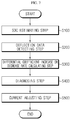
- FIG. 7 is a flowchart for schematically illustrating a method for diagnosing battery according to still another embodiment of the present disclosure.
- ⁇ processor> described in the specification refers to a unit that processes at least one function or operation, and may be implemented by hardware, software, or a combination of hardware and software.
- FIG. 1 is a diagram showing a apparatus for diagnosing battery according to an embodiment of the present disclosure
- FIG. 2 is a graph showing a voltage of a battery according to a SOC of a full cell of the battery
- FIGS. 3 and 4 are voltage differential graphs of the battery according to the SOC of the battery before and after smoothing
- FIG. 5 is a voltage differential graph of a battery according to a SOC of a diagnosis target battery from which one inflection point is detected and a voltage differential graph of a battery according to a SOC of a battery in a BOL state
- FIG. 6 is a voltage differential graph of a battery according to a SOC of a diagnosis target battery from which a plurality of inflection points are detected and a voltage differential graph of a battery according to a SOC of a battery in a BOL state.
- a apparatus for diagnosing battery 100 may be included in a battery pack 1 that has a battery B and may be connected to the battery B to diagnose a change of an electrode reaction resistance of the battery B.
- the apparatus for diagnosing battery 100 may be included in a battery management system (BMS) provided in the battery pack 1 .
- BMS battery management system
- the apparatus for diagnosing battery 100 may include a sensing unit 110 , a memory unit 120 , a processor 130 and a notifying unit 140 .
- the battery B is a minimum unit cell whose change of an electrode reaction resistance is diagnosed, and includes a plurality of unit cells electrically connected in series and/or in parallel.
- the battery pack B includes only one unit cell also falls into the scope of the present disclosure.
- the battery B may be a lithium polymer battery of a pouch type.
- the battery B may be electrically coupled to various types of external devices through an external terminal.
- the external device may be, for example, an electric vehicle, a hybrid electric vehicle, a flying object such as a drone, a large-capacity energy storage system (ESS) included in an electrical grid, or a mobile device.
- the battery B may include some or all unit cells included in a modularized battery pack mounted in the external device.
- the external terminal of the battery B may be selectively coupled to a charging device.
- the charging device may be selectively coupled to the battery B by the control of the external device to which the battery pack B is mounted.
- the sensing unit 110 is operably coupled to the processor 130 . That is, the sensing unit 110 may be connected to the processor 130 to transmit an electrical signal to the processor 130 or receive an electrical signal from the processor 130 .
- the sensing unit 110 may repeatedly measure a voltage applied between a positive electrode and a negative electrode of the battery B and a current flowing into or out of the battery B at predetermined intervals, and provide a measurement signal indicating the measured voltage and current to the processor 130 .
- the sensing unit 110 includes a current sensor configured to measure the current of the battery B. Also, the sensing unit 110 may further include a voltage sensor configured to measure the voltage of the battery B. Though not shown in FIG. 1 , the current sensor may be connected to both ends of a sense resistor connected to the battery B through a circuit. That is, the current sensor may measure a potential difference between both ends of the sense resistor and measure the current of the battery B based on the measured potential difference and the resistance value of the sense resistor.
- the processor 130 may determine a digital value of each of voltage and current of the battery through signal processing, and store the digital value in the memory unit 120 .
- the memory unit 120 is a semiconductor memory device that records, erases and updates data generated by the processor 130 , and stores a plurality of program codes prepared for diagnosing a change of an electrode reaction resistance of the battery B.
- the memory unit 120 may store preset values of various predetermined parameters used in implementing the present disclosure.
- the memory unit 120 may is not particularly limited as long as it is a semiconductor memory element known in the art as being capable of recording, erasing and updating data.
- the memory unit 120 may be dynamic random-access memory (DRAM), synchronous dynamic-random access memory (SDRAM), a flash memory, read-only memory (ROM), electrically erasable programmable read-only memory (EEPROM), a register, and the like.
- the memory unit 120 may further include a storage medium that stores program codes defining the control logics of the processor 130 .
- the storage medium includes a non-volatile storage element such as a flash memory or a hard disk.
- the memory unit 120 may be physically separate from the processor 130 or may be integrated with the processor 130 .
- the processor 130 may control the current of the battery B so that the current of a preset charging current value is inputted to the battery B to charge the battery B, and estimate a State Of Charge (SOC) of the battery B based on the current input to the battery B.
- SOC State Of Charge
- the preset charging current value may be calculated using Equation 1 below.
- I C ⁇ C n [Equation 1]
- Ic may be a preset charging current value
- ⁇ may be a constant of 1 or less
- Cn may be a rated current of the battery.
- the processor 130 may estimate the SOC of the battery B which is charged by receiving the current having a charging current value equal to or less than the rated current.
- the SOC of the battery B may be a ratio of a charged capacity to the total capacity of the battery B.
- the processor 130 may estimate the SOC of the battery B by using a current integration method that integrates current values of the current input to the battery B.
- the processor 130 estimates the SOC of the battery B by using the current integration method
- the estimation method is not limited thereto as long as the SOC of the battery B to which the current of a preset charging current value is input can be estimated.
- the processor 130 may generate SOC-voltage data of the battery B by mapping the voltage of the battery B with the estimated SOC of the battery B.
- the voltage of the battery B may be an open circuit voltage of the battery B.
- the SOC-voltage data of the battery B may be expressed using a voltage curve of the battery B according to the SOC of the battery B, as shown in FIG. 2 .
- the memory unit 120 may store the SOC-voltage data of the battery B in at least one form of an approximation function that approximates the SOC-voltage data of the battery B to the voltage curve of the battery B according to the SOC of the battery B and a lookup table where the voltage of the battery B is mapped with each SOC of the battery B.
- the processor 130 may detect a plurality of inflection points from the SOC-voltage data of the battery B and detect a plurality of inflection data about the voltage and SOC about the plurality of inflection points.
- the inflection data may include a voltage and a SOC at an inflection point in a SOC-voltage curve expressed based on the SOC-voltage data.
- the processor 130 may detect the SOC and the voltage of the battery B at a point where the change of the voltage of the battery B increases and then decreases according to a minute change of the SOC based on the SOC-voltage data as the inflection data. Also, the processor 130 may detect the SOC and the voltage of the battery B at a point where the change of the voltage of the battery B decreases and then increases according to the minute change of the SOC based on the SOC-voltage data as the inflection data. That is, the processor 130 may detect the SOC where a second-order derivative coefficient of an approximation function corresponding to the SOC-voltage data of the battery B is “0” and the voltage of the battery B corresponding to the SOC as the inflection point.
- the processor 130 may calculate a first-order derivative by differentiating the approximation function corresponding to the SOC-voltage data of the battery B, as shown in FIG. 3 .
- the processor 130 may remove noise components by smoothing the first-order derivative of the approximation function corresponding to the SOC-voltage data of the battery B, as shown in FIG. 4 .
- the processor 130 may smooth the first-order derivative of the approximation function corresponding to the SOC-voltage data of the battery B by using a noise filter. In this way, the processor 130 may prevent false detection of the inflection point caused by noise components, thereby improving the accuracy of inflection point detection.
- the processor 130 may calculate a second-order derivative by differentiating the first-order derivative of the smoothed approximation function, and detect the SOC where a function value of the calculated second-order derivative is “0” and the voltage of the battery B corresponding to the SOC as the inflection data.
- the processor 130 may detect seven inflection points a 1 to a 7 , and the SOC corresponding to the seven inflection points a 1 to a 7 may be “7.2%”, “13.6%”, “19.1%”, “21.2%”, “35.3%”, “56.8%” and “60.0%”, respectively.
- the differential coefficients corresponding to seven inflection points a 1 to a 7 detected by the processor 130 may be “0.005”, “0.011”, “0.0085”, “0.009”, “0.003”, “0.015” and “0.009”, respectively.
- the differential coefficient may be a function value of a first-order derivative at the detected inflection point.
- the differential coefficient may be a Y-axis value in FIGS. 3 and 4 , which is expressed as dV/dSOC.
- the processor 130 may calculate a differential coefficient increase or decrease rate at each of the plurality of inflection data detected based on a preset reference differential coefficient.
- the preset reference differential coefficient may be a differential coefficient of the inflection data detected from the SOC-voltage data of a battery B in a beginning of life (BOL) state without degradation.
- the processor 130 may use the differential coefficient obtained from the battery in a BOL state as the reference differential coefficient, identical to the above method for obtaining a differential coefficient from the battery B that is a diagnosis target.
- the processor 130 may calculate the differential coefficient increase or decrease rate by using Equation 2 below.
- I is a differential coefficient increase or decrease rate
- Db is a differential coefficient of the detected inflection data
- Dref is a preset reference differential coefficient.
- Db and Dref may be differential coefficients for the same SOC.
- Db may be a Y-axis value of a
- Dref may be a Y-axis value of b.
- the processor 130 may diagnose the change of an electrode reaction resistance of the battery B depending on whether the plurality of calculated differential coefficient increase or decrease rates belong to a preset reference range.
- the electrode reaction resistance may be a parameter indicating whether a reaction rate of the electrode reaction occurring at an interface between an electrode and a solution is decreased to a reference reaction rate or below since an organic material layer or a gas layer is generated at the electrode due to the degradation of the battery B. For example, if the electrode reaction resistance is increased, an organic material layer or a gas layer may be generated due to the degradation of the battery B to reduce the reaction rate of the electrode reaction.
- the processor 130 may diagnose that the electrode reaction resistance of the battery B is increased if some of the plurality of calculated differential coefficient increase or decrease rates do not belong to a preset reference increase or decrease rate range. On the contrary, the processor 130 may diagnose that the electrode reaction resistance of the battery B is not increased if all of the plurality of calculated differential coefficient increase or decrease rates belong to the preset reference increase or decrease rate range.
- the preset reference increase or decrease rate range may be a range of “ ⁇ 10% or above and 0% or below”. For example, if the differential coefficient at the inflection data is increased over the preset reference differential coefficient, this may correspond to a case where the electrode reaction resistance of the battery B is decreased. On the contrary, if the differential coefficient at the inflection data is decreased below the preset reference differential coefficient, this may correspond to a case where the electrode reaction resistance of the battery B is increased.
- the processor 130 may detect inflection data (a) from the SOC-voltage data of the battery B.
- the inflection data (a) may be an inflection point in the SOC-voltage curve.
- the processor 130 may read a differential coefficient corresponding to inflection data (a) by using the SOC-voltage data of the battery B. That is, the processor 130 may read the dV/dSOC value “0.003” corresponding to the inflection data (a).
- the processor 130 may calculate a differential coefficient increase or decrease rate of the inflection data (a) by using the differential coefficient “0.006” of the inflection data (b) detected in advance from the SOC-voltage data of the battery in a BOL state.
- the processor 130 may calculate the differential coefficient increase or decrease rate of the inflection data (a) as “ ⁇ 50%” by using Equation 2.
- the processor 130 may diagnose the change of the electrode reaction resistance of the battery B depending on whether the calculated differential coefficient increase or decrease rate is included in the preset reference increase or decrease rate range. For example, in the former embodiment, the processor 130 may determine that the calculated differential coefficient increase or decrease rate “ ⁇ 50%” is not included in the preset reference increase or decrease rate range “ ⁇ 10% or above and 0% or below”. The processor 130 may diagnose that the electrode reaction resistance of the battery B is increased.
- the configuration of the present disclosure it is possible to accurately diagnose whether the battery B is degraded due to an increase of the electrode reaction resistance by using the increase or decrease of the differential coefficient at the inflection point detected from the SOC-voltage data of the battery B.
- the processor 130 may be configured to adjust the magnitude of a charge or discharge current of the battery only when it is diagnosed that the electrode reaction resistance of the battery B is increased. Specifically, if the calculated differential coefficient increase or decrease rate is not included in the preset reference increase or decrease rate range, the processor 130 may adjust the magnitude of the charge or discharge current of a preset battery based on the calculated differential coefficient increase or decrease rate.
- the processor 130 may reduce the magnitude of the charge or discharge current of the preset battery by 50%.
- the battery diagnosis apparatus may prevent unexpected problems such as overcharge or overdischarge in advance.
- the processor 130 may read a differential coefficient at each of the detected plurality of inflection data and calculate increase or decrease rates of the plurality of read differential coefficients.
- a processor 130 when detecting a plurality of inflection data a 1 to a 7 from the SOC-voltage data of the battery B, a processor 130 may read Y-axis values at the plurality of detected inflection data a 1 to a 7 as differential coefficients.
- the differential coefficients at the plurality of inflection data a 1 to a 7 may be “0.0045”, “0.0105”, “0.0080”, “0.0085”, “0.0025”, “0.0145” and “0.0056”.
- the processor 130 may calculate a differential coefficient increase or decrease rate by using a difference between the reference differential coefficients “0.005”, “0.011”, “0.0085”, “0.009”, “0.003”, “0.015” and “0.009” at a plurality of inflection data b 1 to b 7 detected from the SOC-voltage data of the battery in a BOL state and the differential coefficients “0.0045”, “0.0105”, “0.008”, “0.0085”, “0.0025”, “0.0145” and “0.0056” at the plurality of detected inflection data a 1 to a 7 .
- the inflection data a 1 to a 7 may correspond to the same SOC as the inflection data b 1 to b 7 .
- the inflection data a 1 and b 1 may have the same SOC
- the inflection data a 2 and b 2 may have the same SOC
- the SOC of the inflection data a 3 to a 7 may be identical to the SOC of the inflection data b 3 to b 7 .
- the processor 130 may calculate an increase or decrease rate of each of the differential coefficients “0.0045”, “0.0105”, “0.008”, “0.0085”, “0.0025”, “0.0145” and “0.0056” corresponding to the plurality of inflection data a 1 to a 7 detected from the SOC-voltage data of the battery B by using Equation 2.
- the processor 130 may calculate the differential coefficient increase or decrease rates of the plurality of differential coefficients “0.0045”, “0.0105”, “0.0080”, “0.0085”, “0.0025”, “0.0145” and “0.0056” at the plurality of inflection data a 1 to a 7 detected from the SOC-voltage data of the battery B as “ ⁇ 10%”, “ ⁇ 4.54%”, “ ⁇ 5.88%”, “ ⁇ 5.56%”, “ ⁇ 16.67%”, “ ⁇ 3.33%” and “ ⁇ 37.78%”, respectively.
- the processor 130 may determine whether each of the plurality of calculated increase or decrease rates belongs to the preset reference increase or decrease rate range, and diagnose the change of the electrode reaction resistance of the battery B based on the number of differential coefficient increase or decrease rates not included in the preset reference increase or decrease rate range among the plurality of differential coefficient increase or decrease rates. Namely, the processor 130 may diagnose that the electrode reaction resistance of the battery B is increased if the number of increase or decrease rates not included in the reference increase or decrease rate range among the plurality of differential coefficient increase or decrease rates is a preset reference number or above.
- the processor 130 may calculate the plurality of differential coefficient increase or decrease rates “ ⁇ 10%”, “ ⁇ 4.54%”, “ ⁇ 5.88%”, “ ⁇ 5.56%”, “ ⁇ 16.67%”, “ ⁇ 3.33%” and “ ⁇ 37.78%”.
- the processor 130 may calculate that the number of differential coefficient increase or decrease rates belonging to the preset reference increase or decrease rate range “ ⁇ 10% or above and 0% or below” among the calculated differential coefficient increase or decrease rates is 5. Namely, among the seven calculated differential coefficient increase or decrease rates, two differential coefficient increase or decrease rates may not belong to the preset differential coefficient increase or decrease rate range. Since the number of differential coefficient increase or decrease rates belonging to the preset differential coefficient increase or decrease rate range among the calculated differential coefficient increase or decrease rates is greater than the preset reference number, the processor 130 may diagnose that the electrode reaction resistance of the battery B is increased.
- the processor 130 may select an increase or decrease rate having a largest absolute value among the calculated differential coefficient increase or decrease rates, and adjust the magnitude of the preset charge or discharge current of the battery B based on the selected increase or decrease rate.
- the processor 130 may select “ ⁇ 37.78%” as the differential coefficient increase or decrease rate having a largest magnitude. In addition, the processor 130 may reduce the magnitude of the preset charge or discharge current of the battery B by 37.78%.
- the processor 130 may diagnose the change of the electrode reaction resistance of the battery B by using a differential coefficient at some of the plurality of detected inflection data. Specifically, the processor 130 may select an n number of inflection data having a largest SOC among the plurality of detected inflection data, and select the differential coefficients at the n number of selected inflection data as a first differential coefficient to an n th differential coefficient.
- n may be a preset number.
- the processor 130 may select two inflection data having largest SOCs among the plurality of inflection data a 1 to a 7 detected from the SOC-voltage data of the battery B. In this case, the processor 130 may select the differential coefficient “0.0056” of the inflection data “a 7 ” as the first differential coefficient, and select the differential coefficient “0.0145” of the inflection data “a 6 ” as the second differential coefficient.
- the processor 130 may calculate a first differential coefficient increase or decrease rate based on the first differential coefficient and calculate a second differential coefficient increase or decrease rate based on the second differential coefficient, by using Equation 2.
- the processor 130 may select the inflection data “b 7 ” and “b 6 ” respectively corresponding to the inflection data “a 7 ” and “a 6 ” among the plurality of inflection data b 1 to b 7 detected from the SOC-voltage data of the battery in a BOL state.
- the processor 130 may read the reference differential coefficient “0.009” corresponding to the inflection data “b 7 ” and the reference differential coefficient “0.015” corresponding to the inflection data “b 6 ”. After that, the processor 130 may calculate the first differential coefficient increase or decrease rate as “ ⁇ 37.78%” and calculate the second differential coefficient increase or decrease rate as “ ⁇ 3.3%” by using Equation 2.
- the processor 130 may diagnose that the electrode reaction resistance of the battery B is increased. In addition, the processor 130 may reduce the magnitude of the preset charge or discharge current of the battery B by 37.78%. Namely, if the preset charge current has a magnitude of 1C, the processor 130 may reduce the magnitude of the charge current to 0.6221C.
- the battery diagnosis apparatus may quickly and easily diagnose the change of the electrode reaction resistance of the battery B by using only the differential coefficients corresponding to some inflection data sensitive to the degradation of the battery B, instead of using the differential coefficients corresponding to all the inflection data detected from the SOC-voltage data of the battery B.
- the processor 130 may classify the inflection data detected from the SOC-voltage data of the battery B into any one of a first inflection data group and a second inflection data group.
- the first inflection data group may be a point at which the change of the voltage of the battery B according to a minute change of the SOC increases and then decreases
- the second inflection data group may be a point at which the change of the voltage of the battery B according to a minute change of the SOC decreases and then increases.
- the inflection data a 1 , a 3 , a 5 and a 7 may be classified into the first inflection data group, and the inflection data a 2 , a 4 and a 6 may be classified into the second inflection data group.
- the processor 130 may calculate the differential coefficient increase or decrease rate at the inflection data belonging to the first inflection data group and the second inflection data group.
- the processor 130 may determine whether each differential coefficient increase or decrease rate at the plurality of inflection data belonging to the first inflection data group is less than the preset first reference increase or decrease rate and determine whether each differential coefficient increase or decrease rate at the plurality of inflection data belonging to the second inflection data group is greater than the preset second reference increase or decrease rate.
- the processor 130 may diagnose the change of the electrode reaction resistance of the battery B based on the sum of the number of differential coefficient increase or decrease rates less than the first reference increase or decrease rate among the differential coefficient increase or decrease rates at the plurality of inflection data belonging to the first inflection data group and the number of differential coefficient increase or decrease rates greater than second reference increase or decrease rate among the differential coefficient increase or decrease rates at the plurality of inflection data belonging to the second inflection data group.
- the preset reference number is set as 1 and also the differential coefficient increase or decrease rates corresponding to the inflection data a 1 to a 7 are calculated as “ ⁇ 10%”, “ ⁇ 4.54%”, “ ⁇ 5.88%”, “ ⁇ 5.56%”, “ ⁇ 16.67%”, “ ⁇ 3.33%” and “ ⁇ 37.78%”, respectively. Also, it is assumed that the first reference increase or decrease rate is set as “ ⁇ 10%” and the second reference increase or decrease rate is set as “10%”.
- the processor 130 may select “a 5 ” and “a 7 ” as the inflection data whose differential coefficient increase or decrease rate is less than the first reference increase or decrease rate among the plurality of inflection data a 1 , a 3 , a 5 and a 7 belonging to the first inflection data group.
- the processor 130 may select no inflection data as the inflection data whose differential coefficient increase or decrease rate is greater than the second reference increase or decrease rate among the plurality of inflection data a 2 , a 4 and a 6 belonging to the second inflection data group. Namely, the processor 130 may select two inflection data in total.
- the processor 130 since the number of selected inflection data is greater than the preset reference number, the processor 130 may diagnose that the electrode reaction resistance of the battery B is increased.
- the processor 130 may diagnose that the electrode reaction resistance of the battery B is increased.
- the processor 130 may select the inflection data having a smallest SOC as the first inflection data and the inflection data having a largest SOC as the second inflection data among the plurality of inflection data. In addition, the processor 130 may calculate a differential coefficient increase or decrease rate corresponding to the first inflection data and a differential coefficient increase or decrease rate corresponding to the second inflection data.
- the processor 130 may select a 1 as the first inflection data and a 7 as the second inflection data.
- the processor 130 may select the first differential coefficient “0.0045” corresponding to a 1 and the second differential coefficient “0.0056” corresponding to a 7 .
- the processor 130 may calculate a differential coefficient increase or decrease rate corresponding to the first inflection data and a differential coefficient increase or decrease rate corresponding to the second inflection data by using Equation 2.
- the processor 130 may calculate the differential coefficient increase or decrease rate corresponding to a 1 as “ ⁇ 10%” and the differential coefficient increase or decrease rate corresponding to a 7 as “ ⁇ 37.78%”.
- the processor 130 may determine whether each of the calculated differential coefficient increase or decrease rates is included in the preset reference increase or decrease rate range, and diagnose that the electrode reaction resistance of the battery B is increased if at least one differential coefficient increase or decrease rate is not included in the reference increase or decrease rate range.
- the preset reference increase or decrease rate range is assumed as “ ⁇ 10%” to “0%”, similar to the former example.
- the processor 130 may determine whether the first differential coefficient increase or decrease rate “ ⁇ 10%” and the second differential coefficient increase or decrease rate “ ⁇ 37.78%”, calculated in the former example, are included in the preset reference increase or decrease rate range “ ⁇ 10% or above and 0% or below”. Namely, since the second differential coefficient increase or decrease rate “ ⁇ 37.78%” is not included in the present reference increase or decrease rate range, the processor 130 may determine that at least one differential coefficient increase or decrease rate is not included in the reference increase or decrease rate range and thus diagnose that the electrode reaction resistance of the battery B is increased.
- the processor 130 may transmit a message indicating the diagnosis result to the external device through a communication terminal (COM).
- COM communication terminal
- the processor 130 may selectively include an application-specific integrated circuit (ASIC), another chipset, a logic circuit, a register, a communication modem, and a data processing device. At least one of the various control logics executable by the processor 130 may be combined, and the combined control logic is written in a computer-readable code system and recorded on a computer-readable recording medium.
- the recording medium has no limitation as long as it can be accessed by the processor 130 included in a computer.
- the recording medium includes at least one selected from the group consisting of a ROM, a RAM, a register, a CD-ROM, a magnetic tape, a hard disk, a floppy disk and an optical data recording device.
- the code system may be modulated into a carrier signal and stored in a communication carrier at a specific time, and may be stored and executed in a distributed manner on computers connected through a network.
- functional programs, code and segments for implementing the combined control logics may be easily inferred by programmers in the technical field to which the present disclosure belongs.
- the notifying unit 140 may receive and output the diagnosis results obtained by the processor 130 to the outside. More specifically, the notifying unit 140 may include at least one of a display unit for displaying the diagnosis result by using at least one of symbols, numbers and codes, and a speaker unit for outputting the diagnosis result with a sound.
- a battery management system may include the apparatus for diagnosing battery described above. By doing so, it is possible to diagnose the change of an electrode reaction resistance of a battery managed by the battery management system.
- FIG. 7 is a flowchart for schematically illustrating a method for diagnosing battery according to still another embodiment of the present disclosure.
- Thea battery diagnosis method according to an embodiment of the present disclosure is may be performed in the apparatus for diagnosing battery.
- a method for diagnosing battery may include a SOC estimating step (S 100 ), an inflection data detecting step (S 200 ), a differential coefficient increase or decrease rate calculating step (S 300 ), a diagnosing step (S 400 ) and a current adjusting step (S 500 ).
- the SOC estimating step (S 100 ) is a step of measuring a current and voltage of a battery B and estimating a SOC of the battery B based on the measured current. Based on the current of the battery B measured by the sensing unit 110 , the processor 130 may estimate the SOC of the battery B.
- the sensing unit 110 may measure the voltage and current of the battery B and transmit the measured voltage value and the measured current value to the processor 130 .
- the processor 130 may receive the voltage value and the current value from the sensing unit 110 and estimate the SOC of the battery B based on the received current value.
- the inflection data detecting step (S 200 ) is a step of detecting a plurality of inflection data from SOC-voltage data of the battery where the measured voltage and the estimated SOC are mapped and may be performed by the processor 130 .
- the processor 130 may obtain the SOC-voltage data where the voltage value received from the sensing unit 110 and the estimated SOC are mapped with each other, and extract a plurality of inflection points from the obtained SOC-voltage data.
- the processor 130 may select some inflection data that satisfy the predetermined condition among the plurality of extracted inflection data. For example, the processor 130 may select only some inflection data having a largest SOC among the plurality of extracted inflection data. In addition, the processor 130 may select the inflection data having a largest SOC and the inflection data having a smallest SOC among the plurality of extracted inflection data.
- the differential coefficient increase or decrease rate calculating step (S 300 ) is a step of calculating a differential coefficient increase or decrease rate at each of the plurality of inflection data detected based on the preset reference differential coefficient, and may be performed by the processor 130 .
- the processor 130 may calculate the differential coefficient increase or decrease rate at each of the plurality of detected inflection data by using Equation 2.
- the preset reference differential coefficients at the plurality of inflection data b 1 to b 7 are set as “0.005”, “0.011”, “0.0085”, “0.009”, “0.003”, “0.015” and “0.009”, respectively.
- the differential coefficients at the plurality of detected inflection data a 1 to a 7 are set as “0.0045”, “0.0105”, “0.008”, “0.0085”, “0.0025”, “0.0145” and “0.0056”, respectively.
- the processor 130 may calculate the differential coefficient increase or decrease rates at the inflection data a 1 to a 7 as “ ⁇ 10%”, “ ⁇ 4.54%”, “ ⁇ 5.88%”, “ ⁇ 5.56%”, “ ⁇ 16.67%”, “ ⁇ 3.33%” and “ ⁇ 37.78%”, respectively, based on the preset reference differential coefficient and Equation 2.
- the diagnosing step (S 400 ) is a step of diagnosing the change of the electrode reaction resistance of the battery depending on whether the plurality of calculated differential coefficient increase or decrease rates belong to the preset reference increase or decrease rate range, and may be performed by the processor 130 .
- the processor 130 may calculate the differential coefficient increase or decrease rate at each of the plurality of inflection data and then determine whether the plurality of calculated differential coefficient increase or decrease rates belong to the preset reference increase or decrease rate range.
- the preset reference increase or decrease rate range is preset as the range of “ ⁇ 10% or above and 0% or below”.
- the processor 130 may calculate the number of differential coefficient increase or decrease rates not belonging to the preset reference increase or decrease rate range among the differential coefficient increase or decrease rates “ ⁇ 10%”, “ ⁇ 4.54%”, “ ⁇ 5.88%”, “ ⁇ 5.56%”, “ ⁇ 16.67%”, “ ⁇ 3.33%” and “ ⁇ 37.78%” at the inflection data a 1 to a 7 .
- the processor 130 may calculate the number of differential coefficient increase or decrease rates not belonging to the preset reference increase or decrease rate range as 2.
- the processor 130 may determine that the electrode reaction resistance of the battery B is increased.
- the processor 130 may diagnose that the electrode reaction resistance of the battery B is increased.
- the current adjusting step (S 500 ) is a step of adjusting the magnitude of the charge or discharge current of the battery only when it is diagnosed that the electrode reaction resistance is increased, and may be performed by the processor 130 .
- the processor 130 may adjust the magnitude of the charge or discharge current of the battery B only when it is diagnosed that the electrode reaction resistance of the battery B is increased.
- the processor 130 since the processor 130 diagnoses that the electrode reaction resistance of the battery B is increased, the magnitude of the charge or discharge current of the battery B may be adjusted. At this time, the processor 130 may adjust the magnitude of the charge or discharge current of the battery B based on the differential coefficient increase or decrease rate having a largest absolute value. Since the differential coefficient increase or decrease rate having a largest absolute value is “ ⁇ 37.78%” in the former embodiment, the processor 130 may reduce the magnitude of the charge or discharge current of the battery B by 37.78%.
Abstract
Description
I C =α×C n [Equation 1]
- 1: battery pack
- B: battery
- 100: apparatus for diagnosing battery
- 110: sensing unit
- 120: memory unit
- 130: processor
- 140: notifying unit
Claims (10)
Applications Claiming Priority (3)
| Application Number | Priority Date | Filing Date | Title |
|---|---|---|---|
| KR20180041691 | 2018-04-10 | ||
| KR10-2018-0041691 | 2018-04-10 | ||
| PCT/KR2019/004289 WO2019199058A1 (en) | 2018-04-10 | 2019-04-10 | Apparatus and method for diagnosing battery |
Publications (2)
| Publication Number | Publication Date |
|---|---|
| US20200271727A1 US20200271727A1 (en) | 2020-08-27 |
| US11150307B2 true US11150307B2 (en) | 2021-10-19 |
Family
ID=68163721
Family Applications (1)
| Application Number | Title | Priority Date | Filing Date |
|---|---|---|---|
| US16/643,907 Active 2039-04-22 US11150307B2 (en) | 2018-04-10 | 2019-04-10 | Apparatus and method for diagnosing battery |
Country Status (6)
| Country | Link |
|---|---|
| US (1) | US11150307B2 (en) |
| EP (1) | EP3674731A4 (en) |
| JP (1) | JP6870187B2 (en) |
| KR (1) | KR102343422B1 (en) |
| CN (1) | CN111164437B (en) |
| WO (1) | WO2019199058A1 (en) |
Families Citing this family (10)
| Publication number | Priority date | Publication date | Assignee | Title |
|---|---|---|---|---|
| EP3690461B1 (en) | 2018-04-10 | 2022-06-29 | LG Energy Solution, Ltd. | Apparatus and method for diagnosing a battery |
| KR20210074001A (en) | 2019-12-11 | 2021-06-21 | 주식회사 엘지에너지솔루션 | Apparatus of Controlling Operation of Secondary Battery using Relative Deterioration Degree of Electrode and Method thereof |
| KR20210079085A (en) * | 2019-12-19 | 2021-06-29 | 주식회사 엘지에너지솔루션 | Apparatus, method and computer program for updating current pattern for quick charge |
| KR20210141096A (en) * | 2020-05-15 | 2021-11-23 | 주식회사 엘지에너지솔루션 | Apparatus and method for diagnosing battery state |
| KR20220048371A (en) | 2020-10-12 | 2022-04-19 | 주식회사 엘지에너지솔루션 | Apparatus and method for diagnosing battery |
| CN112525958B (en) * | 2020-12-03 | 2023-04-25 | 蜂巢能源科技有限公司 | Method for measuring actual pre-lithium of pre-lithium ion battery |
| KR20220094464A (en) * | 2020-12-29 | 2022-07-06 | 주식회사 엘지에너지솔루션 | Battery diagnosis system, battery diagnosis method, battery pack, and electric vehicle |
| KR20220107550A (en) * | 2021-01-25 | 2022-08-02 | 주식회사 엘지에너지솔루션 | Apparatus and method for classifying battery |
| CN113386622B (en) * | 2021-06-29 | 2023-03-31 | 摩拜(北京)信息技术有限公司 | Vehicle control method and device and vehicle |
| CN117388734A (en) | 2022-07-05 | 2024-01-12 | 通用汽车环球科技运作有限责任公司 | Health-based operation for a vehicle power supply |
Citations (22)
| Publication number | Priority date | Publication date | Assignee | Title |
|---|---|---|---|---|
| CN1437031A (en) | 2002-02-08 | 2003-08-20 | 上海华谊(集团)公司 | Battery capacity measuring method |
| JP2004031254A (en) | 2002-06-28 | 2004-01-29 | Nissan Motor Co Ltd | Capacity control device and method for battery pack |
| US20090243548A1 (en) | 2008-03-31 | 2009-10-01 | A123 Systems, Inc. | Method For Detecting Cell State-Of-Charge and State-Of-Discharge Divergence Of A Series String of Batteries Or Capacitors |
| EP2239804A2 (en) | 2004-10-29 | 2010-10-13 | Medtronic, Inc. | Method of charging lithium-ion battery |
| US20120226455A1 (en) | 2011-03-01 | 2012-09-06 | Hitachi, Ltd. | Anomalously Charged State Detection Device and Test Method for Lithium Secondary Cell |
| US20130314050A1 (en) * | 2012-05-28 | 2013-11-28 | Sony Corporation | Charge control device for secondary battery, charge control method for secondary battery, charge state estimation device for secondary battery, charge state estimation method for secondary battery, degradation degree estimation device for secondary battery, degradation degree estimation method for secondary battery, and secondary battery device |
| CN103969590A (en) | 2013-02-05 | 2014-08-06 | 三星Sdi株式会社 | Battery management system and method of using same |
| CN104364669A (en) | 2012-06-13 | 2015-02-18 | 株式会社Lg化学 | Apparatus and method for estimating state of charge state of charge of secondary cell including mixed cathode material |
| US20150051854A1 (en) | 2012-12-03 | 2015-02-19 | Lg Chem, Ltd. | Apparatus and method for estimating parameter of secondary battery |
| US20150147614A1 (en) | 2013-11-23 | 2015-05-28 | Hrl Laboratories, Llc | Voltage protection and health monitoring of batteries with reference electrodes |
| US20150226809A1 (en) | 2012-12-04 | 2015-08-13 | Lg Chem, Ltd. | Apparatus for estimating depth of discharge (dod) of secondary battery |
| US20150285866A1 (en) | 2014-04-04 | 2015-10-08 | GM Global Technology Operations LLC | Systems and methods for estimating battery pack capacity |
| US20160061908A1 (en) | 2014-09-01 | 2016-03-03 | Yokogawa Electric Corporation | Secondary battery capacity measurement system and secondary battery capacity measurement method |
| JP2016053564A (en) | 2014-09-01 | 2016-04-14 | 横河電機株式会社 | Secondary battery capacity measurement system and secondary battery capacity measurement method |
| WO2016147572A1 (en) | 2015-03-13 | 2016-09-22 | パナソニックIpマネジメント株式会社 | Cell management device and power supply device |
| US9461490B2 (en) | 2013-03-13 | 2016-10-04 | GM Global Technology Operations LLC | Method and apparatus for evaluating a rechargeable battery |
| KR20170023583A (en) | 2015-08-24 | 2017-03-06 | 주식회사 엘지화학 | Detection method of Li plating, method and apparatus for charging secondary battery and secondary battery system using the same |
| KR20170045730A (en) | 2015-10-19 | 2017-04-27 | 리튬 에너지 앤드 파워 게엠베하 운트 코. 카게 | Method for determining an aging state of a battery, method for controlling a battery and operating apparatus |
| KR20170073314A (en) | 2015-12-18 | 2017-06-28 | 울산과학기술원 | Method for charging and discharging lithium secondary battery |
| DE102016000988A1 (en) | 2015-12-24 | 2017-06-29 | Daimler Ag | Method and device for detecting a divergent behavior of parallel-connected battery cells |
| US20170259687A1 (en) | 2016-03-10 | 2017-09-14 | Ford Global Technologies, Llc | Circuit and method for detection of battery cell degradation events |
| EP3287801A1 (en) | 2015-08-18 | 2018-02-28 | LG Chem, Ltd. | Method for predicting battery charge limit, and method and apparatus for rapidly charging battery using same |
Family Cites Families (7)
| Publication number | Priority date | Publication date | Assignee | Title |
|---|---|---|---|---|
| JP4561859B2 (en) * | 2008-04-01 | 2010-10-13 | トヨタ自動車株式会社 | Secondary battery system |
| CN104931882B (en) * | 2014-03-21 | 2018-04-20 | 比亚迪股份有限公司 | The method and apparatus of power battery cubage correction |
| JP2015225846A (en) | 2014-05-30 | 2015-12-14 | トヨタ自動車株式会社 | Power storage system |
| JP6164503B2 (en) * | 2015-06-25 | 2017-07-19 | トヨタ自動車株式会社 | Secondary battery internal resistance estimation method and output control method |
| WO2017028020A1 (en) | 2015-08-14 | 2017-02-23 | Henkel Ag & Co. Kgaa | Sinterable composition for use in solar photovoltaic cells |
| US11173775B2 (en) * | 2016-01-20 | 2021-11-16 | Ford Global Technologies, Llc | Closed loop feedback control to mitigate lithium plating in electrified vehicle battery |
| JP2017133870A (en) * | 2016-01-26 | 2017-08-03 | トヨタ自動車株式会社 | Device for detecting abnormal degradation of lithium ion secondary battery and method for detecting abnormal degradation |
-
2019
- 2019-04-10 KR KR1020190042150A patent/KR102343422B1/en active IP Right Grant
- 2019-04-10 US US16/643,907 patent/US11150307B2/en active Active
- 2019-04-10 WO PCT/KR2019/004289 patent/WO2019199058A1/en unknown
- 2019-04-10 JP JP2020512021A patent/JP6870187B2/en active Active
- 2019-04-10 CN CN201980004766.8A patent/CN111164437B/en active Active
- 2019-04-10 EP EP19786006.7A patent/EP3674731A4/en active Pending
Patent Citations (31)
| Publication number | Priority date | Publication date | Assignee | Title |
|---|---|---|---|---|
| CN1437031A (en) | 2002-02-08 | 2003-08-20 | 上海华谊(集团)公司 | Battery capacity measuring method |
| JP2004031254A (en) | 2002-06-28 | 2004-01-29 | Nissan Motor Co Ltd | Capacity control device and method for battery pack |
| EP2239804A2 (en) | 2004-10-29 | 2010-10-13 | Medtronic, Inc. | Method of charging lithium-ion battery |
| US20090243548A1 (en) | 2008-03-31 | 2009-10-01 | A123 Systems, Inc. | Method For Detecting Cell State-Of-Charge and State-Of-Discharge Divergence Of A Series String of Batteries Or Capacitors |
| KR20100131002A (en) | 2008-03-31 | 2010-12-14 | 에이일이삼 시스템즈 인코포레이티드 | Method for detecting cell state-of-charge and state-of-discharge divergence of a series string of batteries or capacitors |
| US20120226455A1 (en) | 2011-03-01 | 2012-09-06 | Hitachi, Ltd. | Anomalously Charged State Detection Device and Test Method for Lithium Secondary Cell |
| US20130314050A1 (en) * | 2012-05-28 | 2013-11-28 | Sony Corporation | Charge control device for secondary battery, charge control method for secondary battery, charge state estimation device for secondary battery, charge state estimation method for secondary battery, degradation degree estimation device for secondary battery, degradation degree estimation method for secondary battery, and secondary battery device |
| JP2017067790A (en) | 2012-06-13 | 2017-04-06 | エルジー・ケム・リミテッド | Apparatus and method for estimating state of charge of secondary battery including blended cathode material |
| CN104364669A (en) | 2012-06-13 | 2015-02-18 | 株式会社Lg化学 | Apparatus and method for estimating state of charge state of charge of secondary cell including mixed cathode material |
| US20150100260A1 (en) | 2012-06-13 | 2015-04-09 | Lg Chem, Ltd. | Apparatus and method for estimating soc of secondary battery including blended cathode material |
| US20150051854A1 (en) | 2012-12-03 | 2015-02-19 | Lg Chem, Ltd. | Apparatus and method for estimating parameter of secondary battery |
| CN104662432A (en) | 2012-12-03 | 2015-05-27 | 株式会社Lg化学 | Apparatus and method for estimating parameter of secondary battery |
| US20150226809A1 (en) | 2012-12-04 | 2015-08-13 | Lg Chem, Ltd. | Apparatus for estimating depth of discharge (dod) of secondary battery |
| CN104871021A (en) | 2012-12-04 | 2015-08-26 | 株式会社Lg化学 | Method and apparatus for estimating depth of discharge of secondary battery |
| CN103969590A (en) | 2013-02-05 | 2014-08-06 | 三星Sdi株式会社 | Battery management system and method of using same |
| US20140217987A1 (en) | 2013-02-05 | 2014-08-07 | Samsung Sdi Co., Ltd. | Battery management system and driving method thereof |
| US9461490B2 (en) | 2013-03-13 | 2016-10-04 | GM Global Technology Operations LLC | Method and apparatus for evaluating a rechargeable battery |
| US20150147614A1 (en) | 2013-11-23 | 2015-05-28 | Hrl Laboratories, Llc | Voltage protection and health monitoring of batteries with reference electrodes |
| US20150285866A1 (en) | 2014-04-04 | 2015-10-08 | GM Global Technology Operations LLC | Systems and methods for estimating battery pack capacity |
| CN104977541A (en) | 2014-04-04 | 2015-10-14 | 通用汽车环球科技运作有限责任公司 | Systems and methods for estimating battery pack capacity |
| JP2016053564A (en) | 2014-09-01 | 2016-04-14 | 横河電機株式会社 | Secondary battery capacity measurement system and secondary battery capacity measurement method |
| US20160061908A1 (en) | 2014-09-01 | 2016-03-03 | Yokogawa Electric Corporation | Secondary battery capacity measurement system and secondary battery capacity measurement method |
| WO2016147572A1 (en) | 2015-03-13 | 2016-09-22 | パナソニックIpマネジメント株式会社 | Cell management device and power supply device |
| US20170279171A1 (en) | 2015-03-13 | 2017-09-28 | Panasonic Intellectual Property Management Co., Ltd. | Cell management device and power supply device |
| EP3287801A1 (en) | 2015-08-18 | 2018-02-28 | LG Chem, Ltd. | Method for predicting battery charge limit, and method and apparatus for rapidly charging battery using same |
| KR20170023583A (en) | 2015-08-24 | 2017-03-06 | 주식회사 엘지화학 | Detection method of Li plating, method and apparatus for charging secondary battery and secondary battery system using the same |
| US20170234930A1 (en) | 2015-08-24 | 2017-08-17 | Lg Chem, Ltd. | Detection method of li plating, method and apparatus for charging secondary battery and secondary battery system using the same |
| KR20170045730A (en) | 2015-10-19 | 2017-04-27 | 리튬 에너지 앤드 파워 게엠베하 운트 코. 카게 | Method for determining an aging state of a battery, method for controlling a battery and operating apparatus |
| KR20170073314A (en) | 2015-12-18 | 2017-06-28 | 울산과학기술원 | Method for charging and discharging lithium secondary battery |
| DE102016000988A1 (en) | 2015-12-24 | 2017-06-29 | Daimler Ag | Method and device for detecting a divergent behavior of parallel-connected battery cells |
| US20170259687A1 (en) | 2016-03-10 | 2017-09-14 | Ford Global Technologies, Llc | Circuit and method for detection of battery cell degradation events |
Non-Patent Citations (5)
| Title |
|---|
| Extended European Search Report including Written Opinion for Application No. EP19786006.7 dated Dec. 10, 2020, 12 pgs. |
| International Search Report for PCT/KR2019/004289 dated Jul. 25, 2019. |
| Jiang et al, "An Optimal Charging Method for Li-Ion Batteries Using a Fuzzy-Control Approach Based on Polarization Properties", IEEE Transactions on Vehicular Technology, vol. 62, No. 7, Sep. 1, 2013, p. 3000-3009. |
| S.G. Tesfahunegn et al., "A Simplified Battery Charge Controller for Safety and Increased Utilization in Standalone PV Applications", IEEE, Photovoltaic Specialists Conference, Jun. 19, 2011, pp. 2441-2447. |
| Search Report from First Office Action for Chinese Application No. 201980004766.8 dated Aug. 30, 2021; 3 pages. |
Also Published As
| Publication number | Publication date |
|---|---|
| JP6870187B2 (en) | 2021-05-12 |
| EP3674731A1 (en) | 2020-07-01 |
| US20200271727A1 (en) | 2020-08-27 |
| KR20190118535A (en) | 2019-10-18 |
| WO2019199058A1 (en) | 2019-10-17 |
| KR102343422B1 (en) | 2021-12-24 |
| CN111164437B (en) | 2022-05-31 |
| CN111164437A (en) | 2020-05-15 |
| EP3674731A4 (en) | 2021-01-13 |
| JP2020532272A (en) | 2020-11-05 |
Similar Documents
| Publication | Publication Date | Title |
|---|---|---|
| US11150307B2 (en) | Apparatus and method for diagnosing battery | |
| US11193985B2 (en) | Apparatus and method for diagnosing battery | |
| US11391780B2 (en) | Battery diagnostic device and method | |
| US11662388B2 (en) | Apparatus for estimating a battery free capacity | |
| EP3680676B1 (en) | Apparatus, method, battery pack and electrical system for determining electrode information of battery | |
| EP3690462B1 (en) | Battery management apparatus and method | |
| KR20200009920A (en) | Apparatus for diagnosing battery | |
| KR20200078227A (en) | Apparatus and method for diagnosing battery |
Legal Events
| Date | Code | Title | Description |
|---|---|---|---|
| FEPP | Fee payment procedure |
Free format text: ENTITY STATUS SET TO UNDISCOUNTED (ORIGINAL EVENT CODE: BIG.); ENTITY STATUS OF PATENT OWNER: LARGE ENTITY |
|
| AS | Assignment |
Owner name: LG CHEM, LTD., KOREA, REPUBLIC OF Free format text: ASSIGNMENT OF ASSIGNORS INTEREST;ASSIGNORS:BAE, YOON-JUNG;KIM, DAE-SOO;KIM, DONG-KYU;AND OTHERS;REEL/FRAME:052305/0989 Effective date: 20191212 |
|
| STPP | Information on status: patent application and granting procedure in general |
Free format text: APPLICATION DISPATCHED FROM PREEXAM, NOT YET DOCKETED |
|
| STPP | Information on status: patent application and granting procedure in general |
Free format text: DOCKETED NEW CASE - READY FOR EXAMINATION |
|
| STPP | Information on status: patent application and granting procedure in general |
Free format text: NOTICE OF ALLOWANCE MAILED -- APPLICATION RECEIVED IN OFFICE OF PUBLICATIONS |
|
| STPP | Information on status: patent application and granting procedure in general |
Free format text: NOTICE OF ALLOWANCE MAILED -- APPLICATION RECEIVED IN OFFICE OF PUBLICATIONS |
|
| STPP | Information on status: patent application and granting procedure in general |
Free format text: PUBLICATIONS -- ISSUE FEE PAYMENT VERIFIED |
|
| STCF | Information on status: patent grant |
Free format text: PATENTED CASE |
|
| AS | Assignment |
Owner name: LG ENERGY SOLUTION, LTD., KOREA, REPUBLIC OF Free format text: ASSIGNMENT OF ASSIGNORS INTEREST;ASSIGNOR:LG CHEM, LTD.;REEL/FRAME:058295/0068 Effective date: 20211027 |