EP4063742A1 - Steam cooking appliance with a specific fluid line system - Google Patents
Steam cooking appliance with a specific fluid line system Download PDFInfo
- Publication number
- EP4063742A1 EP4063742A1 EP22160249.3A EP22160249A EP4063742A1 EP 4063742 A1 EP4063742 A1 EP 4063742A1 EP 22160249 A EP22160249 A EP 22160249A EP 4063742 A1 EP4063742 A1 EP 4063742A1
- Authority
- EP
- European Patent Office
- Prior art keywords
- fluid line
- adapter
- tank
- cooking appliance
- steam cooking
- Prior art date
- Legal status (The legal status is an assumption and is not a legal conclusion. Google has not performed a legal analysis and makes no representation as to the accuracy of the status listed.)
- Pending
Links
- 239000012530 fluid Substances 0.000 title claims abstract description 192
- 238000010411 cooking Methods 0.000 title claims abstract description 52
- 239000007788 liquid Substances 0.000 claims abstract description 77
- 230000008878 coupling Effects 0.000 claims abstract description 67
- 238000010168 coupling process Methods 0.000 claims abstract description 67
- 238000005859 coupling reaction Methods 0.000 claims abstract description 67
- 230000005484 gravity Effects 0.000 claims abstract description 13
- 238000006073 displacement reaction Methods 0.000 claims description 28
- 238000003780 insertion Methods 0.000 claims description 8
- 230000037431 insertion Effects 0.000 claims description 8
- XLYOFNOQVPJJNP-UHFFFAOYSA-N water Substances O XLYOFNOQVPJJNP-UHFFFAOYSA-N 0.000 description 13
- 238000009423 ventilation Methods 0.000 description 4
- 230000002457 bidirectional effect Effects 0.000 description 3
- 238000007726 management method Methods 0.000 description 3
- 230000037361 pathway Effects 0.000 description 2
- 206010003830 Automatism Diseases 0.000 description 1
- 230000000903 blocking effect Effects 0.000 description 1
- 230000008859 change Effects 0.000 description 1
- 230000006735 deficit Effects 0.000 description 1
- 210000003746 feather Anatomy 0.000 description 1
- 230000001771 impaired effect Effects 0.000 description 1
- 230000006872 improvement Effects 0.000 description 1
- 238000000034 method Methods 0.000 description 1
- NJPPVKZQTLUDBO-UHFFFAOYSA-N novaluron Chemical compound C1=C(Cl)C(OC(F)(F)C(OC(F)(F)F)F)=CC=C1NC(=O)NC(=O)C1=C(F)C=CC=C1F NJPPVKZQTLUDBO-UHFFFAOYSA-N 0.000 description 1
- 230000008569 process Effects 0.000 description 1
- 238000005086 pumping Methods 0.000 description 1
- 230000003245 working effect Effects 0.000 description 1
Images

Classifications
-
- F—MECHANICAL ENGINEERING; LIGHTING; HEATING; WEAPONS; BLASTING
- F24—HEATING; RANGES; VENTILATING
- F24C—DOMESTIC STOVES OR RANGES ; DETAILS OF DOMESTIC STOVES OR RANGES, OF GENERAL APPLICATION
- F24C15/00—Details
- F24C15/003—Details moisturising of air
-
- F—MECHANICAL ENGINEERING; LIGHTING; HEATING; WEAPONS; BLASTING
- F24—HEATING; RANGES; VENTILATING
- F24C—DOMESTIC STOVES OR RANGES ; DETAILS OF DOMESTIC STOVES OR RANGES, OF GENERAL APPLICATION
- F24C15/00—Details
- F24C15/32—Arrangements of ducts for hot gases, e.g. in or around baking ovens
- F24C15/322—Arrangements of ducts for hot gases, e.g. in or around baking ovens with forced circulation
- F24C15/327—Arrangements of ducts for hot gases, e.g. in or around baking ovens with forced circulation with air moisturising
Definitions
- One aspect of the invention relates to a steam cooking appliance according to the preamble of claim 1.
- Steam cooking appliances usually have a steam generation system. This is used to generate steam from a liquid, in particular water, by means of an evaporator of the steam generation system, which steam can then be introduced into the cooking chamber. The steam can be used to prepare food in the cooking chamber. Steam generation systems can be constructed in different ways. Devices are known in this regard that have a corresponding system outside the cooking chamber. This can usually have an evaporator, a vapor separator and a liquid container.
- systems which have a further separate tank in addition to this configuration.
- This tank is intended for external filling.
- Such a further separate tank can be removed from the housing of the steam cooking appliance in order to fill it with water externally to the appliance.
- the separate tank is connected to the fluid line container of the steam generation system via lines.
- water can then be conducted from the tank to the liquid container of the steam generation system by means of a pump of the steam cooking appliance. With a different second pump, residual liquid in the fluid line container can be pumped back to the tank.
- Such systems are component intensive and require two separate pumps.
- the water is fed from the tank to the fluid line container of the steam generation system on the basis of gravity.
- a pump can be saved, for example.
- One aspect of the invention relates to a steam cooking appliance with a housing.
- the steamer also has a cooking chamber. This is formed in the housing.
- the steam cooking appliance also has a steam generation system.
- the steam generation system is arranged in the housing.
- the vapor generation system is intended to generate vapor from liquid. This is intended to be placed in the cooking chamber in order to prepare food with it.
- the steam generation system has a separate tank. This is intended in particular to be filled with liquid externally to the steamer.
- the tank is arranged in the housing. Viewed in the vertical direction of the steam cooking appliance, the tank, in particular in its entirety, is arranged higher than a liquid container of the steam generation system.
- the liquid tank is a separate tank from the tank.
- the steamer also has a pump. This is intended to convey liquid from the liquid container to the tank. In particular, the pump is therefore only intended to convey the liquid in this one direction of flow, namely from the liquid container to the tank.
- the steamer also has a fluid line adapter.
- the tank has a line socket. This fluid line adapter is coupled directly to this line connector of the tank.
- the fluid line adapter and the line connector are separate components in this regard.
- the fluid line adapter has a first, internal fluid line path via which liquid can be routed from the line socket through the fluid line adapter to a coupling socket of the steam cooking appliance. In particular, this conduction is completed when a first operating state of the fluid line adapter in this respect is set.
- the coupling piece is movably arranged on an adapter outlet of the fluid line adapter. In addition, the coupling piece is connected in a fluid-conducting manner to the fluid line container on a first line path, which is measured between the tank and the liquid container.
- the fluid line adapter has a second internal fluid line path, at least partially different from the first, with which liquid can be routed from an adapter inlet of the fluid line adapter, which is different from the adapter outlet of the fluid line adapter, to the line connector. In particular, this routing is completed when a second operating state of the fluid line adapter is set.
- the adapter inlet is fluidly connected to the liquid container on a second line path, which is separate from the first line path.
- it is therefore intended to improve the bidirectional fluid line from the tank to the liquid container by means of a very specific component, namely the fluid line adapter.
- this fluid line adapter is virtually the only component that makes it possible to set the respective flow paths individually and thus to release and block them.
- a highly functional concept can thus be provided. This is implemented in a way that saves both space and components.
- the individual flow paths can be released and blocked individually and in this respect also made possible in a very defined and precise manner. Undesirable leaks can be avoided in this way.
- a clear improvement is achieved precisely in this configuration, in which two pumps are not provided for each of the flow paths, but on the one hand only the principle of gravity is to be implemented and on the other hand only one pump is to be used for return delivery. Undesirably occurring backflows or overflows between the fluid line paths can thereby be avoided.
- the possibility that a relative movement between the coupling piece and the fluid line adapter is made possible also advantageously contributes to the simple, fast and highly functional switching between the two internal fluid line paths.
- the safe movement of the fluid line adapter can also be made possible by this configuration. In particular, due to this configuration, it can be moved, in particular linearly displaceably, as it were between the tank and the coupling piece.
- the tank and the fluid line adapter as well as the coupling socket are arranged in a linear sequence relative to one another.
- a simple axial movement of the fluid line adapter relative to the coupling piece coupled to it enables a simple displacement path.
- This also contributes positively to the fact that the corresponding changeover between the internal fluid line paths is highly functional.
- this also makes it possible for the fluid line adapter to be connected to at least one component of the tank in a relatively movable manner.
- a relative movement of the fluid line adapter to an outer housing of the tank is possible in this respect.
- This also allows the tank to be positioned in different operating positions. In this regard, different positions can then also result in relation to the fluid line adapter.
- This also makes it possible to easily adjust the positions of the components mentioned in relation to one another. This in turn means that the internal fluid line paths of the fluid line adapter can also be released or blocked automatically depending on this with high precision.
- the desired positional changes can be achieved by simple displacements, which then release or block the flow paths.
- the fluid line adapter forms a structural unit.
- This has an adapter outer housing in which the two fluid line paths are formed.
- This adapter outer housing can be tubular.
- this adapter outer housing has a longitudinal axis. This is oriented parallel or coaxially to a longitudinal axis of the coupling piece.
- this longitudinal axis of the adapter outer housing is parallel or coaxial to the longitudinal axis of the tank. It is precisely this configuration that also supports the advantageous, above-mentioned possibilities of relative movement between the components mentioned.
- the individual positioning of the named components in relation to one another can be easily adjusted merely by means of a simple linear displacement.
- the first fluid conduit is part of a gravity fluid conduit as a conduit between the tank and the liquid container.
- the first fluid pathway is part of a gravity fluid pathway that extends between the tank and the liquid container.
- the second fluid line path is part of a pump fluid line path as another line path that extends between the liquid container and the tank.
- a partial path for fluid in the fluid line adapter which starts at the line socket, is part of both the first fluid line path and the second fluid line path.
- This can also support the compact design of the fluid line adapter.
- a clever design of these fluid line paths in the outer housing of the fluid line adapter itself can also save space accordingly.
- the compactness of the entire fluid line adapter can be improved again.
- the fluid line adapter it is then possible for the fluid line adapter to be connected directly to the line socket of the tank at only one coupling point. It is therefore only necessary at the interface between the fluid line adapter and the tank to provide this partial path. At the interface between the fluid line adapter and the tank, it is therefore not necessary to provide two separate sockets that would be provided individually and separately for the two fluid line paths.
- the coupling piece is mounted in the adapter housing in an axially displaceable manner. It extends in all displacement positions on both sides of the adapter outlet.
- the mobility of the coupling piece relative to the adapter housing is to be considered in general terms. This also means that the coupling piece is moved relative to the adapter housing and thus this coupling piece is the moving part.
- This arrangement of the coupling piece, which extends out of the adapter outlet of the adapter outer housing is also a simple connection of this coupling piece to a line allows. The line then leads from the coupling piece to the liquid container of the vapor generation system.
- the coupling piece has at least one seal.
- the outlet of the adapter outer housing is also sealed off by this coupling piece.
- Undesirable leakage of liquid from the adapter outer housing at this adapter outlet can also be avoided as a result. Nevertheless, the relative movement between the coupling piece and the adapter outer housing can be reliably achieved.
- the coupling piece is arranged in a stationary manner on a support base of the steamer.
- the support base is a component that is separate from the adapter outer housing of the fluid line adapter.
- the coupling piece can be arranged mechanically firmly and stably.
- the carrier base is a stable carrier for this coupling socket. Mechanical forces that occur with the relative movement options mentioned above can then be easily absorbed and dissipated by the carrier base.
- the support base can be arranged on a further component of the steamer or a device component of the steamer. For example, this can be a horizontal wall of the steamer. The support of the base can thus be applied to this horizontal wall from above. In this regard, it can be connected to this horizontal wall, which is separate therefrom.
- the horizontal wall can be a ceiling wall. This can be arranged between a top wall of the outer housing of the steamer and a top wall of a muffle of the steamer, which delimits the cooking space. It can be part of a ventilation duct of the steamer.
- the support base can be firmly connected to a separate outer housing of the tank.
- one in particular Movement coupling provided.
- the support base can also be displaced in a motion-coupled manner in this respect.
- a particularly advantageous concept is achieved in order to achieve relative displacements between the coupling piece and the fluid line adapter.
- the fluid line adapter which is arranged between the outer housing of the tank and the coupling piece, is particularly advantageously mounted in a relatively displaceable manner by this mechanical connection of the outer housing of the tank and the support base. This enables the particularly stable mechanical mounting of the fluid line adapter in series between the components mentioned. A particularly precise and linear displacement between the components is thereby achieved.
- the support base is movably arranged on the device component already mentioned above.
- the carrier base has a slot in a base base, so that a linear path of movement of the carrier base is specified by the slot.
- the support base is arranged directly on a further device component and the movement is coupled to the outer housing of the tank and the support base can also be moved to a certain extent relative to the device component.
- a certain amount of guidance for the carrier base is also provided by this elongated hole. This further improves the possibility of linear movement of the carrier base.
- an outer housing of the tank is arranged to be axially movable. It can be provided that the tank has an outer housing and an inner housing.
- the inner housing is the component in which the water is arranged directly. Provision can be made for the outer housing to be arranged such that it can be displaced relative to the inner housing. With this possibility, the position of the outer housing can be changed. Since the outer housing is in particular that component which enables the coupling to tank-external device components, the tank, in particular the outer housing, can be positioned in various defined positions in relation to these device components. This can also result in defined positions, which on the one hand define the intermediate position and on the other hand an end position.
- a respective operating state can then also be characterized in that, on the one hand, the gravitational supply of water to the liquid container is released and the return, in particular the pumping back from the liquid container to the tank, is blocked.
- a concrete state can be defined by the intermediate position, with which the second fluid line path of the fluid line adapter is then released.
- the position of the fluid line adapter that releases either the first fluid line path or the second fluid line path is thus very easily possible for the position of the fluid line adapter that releases either the first fluid line path or the second fluid line path to be automatically set only by adjusting the position of the tank, in particular its outer housing.
- This also provides a particularly simple operating concept for manually releasing or blocking the individual fluid line paths in the fluid line adapter as required. In this exemplary embodiment, this can then be achieved by simply adjusting the tank, in particular the linear adjustment of the outer housing, from the end position to the intermediate position or from the intermediate position to the end position.
- the first fluid line path in the fluid line adapter is automatically released in a first displacement position, the end position, of the outer housing of the tank relative to the fluid line adapter.
- a second displacement position the intermediate position, of the outer housing of the tank relative to the fluid line adapter, the second fluid line path in the fluid line adapter is automatically released.
- the other route is then automatically blocked.
- the displacement movement of the coupling piece in the adapter outer housing or the relative movement between the coupling piece and the adapter outer housing is movement-coupled to the displacement movement of the outer housing of the tank. They therefore carry out the same movement and/or the same movement path.
- the fluid line adapter has a tappet that can be moved, in particular axially. This is arranged in the adapter outer housing.
- the tappet is intended to be provided so that the first fluid line path is released or blocked depending on the operating state of the fluid line adapter.
- the fluid line adapter has a spring. This is particularly coupled to the ram.
- the tappet is pressed into a closed position in the axial direction with this spring in order to block the first fluid line path.
- an automatism is generated which automatically causes this pressing into the closed position during the relative movement between the outer housing of the tank, the fluid line adapter and the coupling piece.
- the tank is coupled to the fluid line adapter with a push-pull device.
- a push-pull device This is a highly functional principle, which on the other hand enables quick coupling and decoupling.
- the tank can be reversibly removed from the housing of the steam cooking appliance and reinserted in order to be filled with liquid, in particular water.
- a switch of the steam cooking appliance is actuated, in which case the pump for returning the liquid from the liquid container to the tank is activated. Even then, an active automatic switching on of the pump can be achieved.
- the steam cooking appliance has a control unit. This controls the process.
- an integrated valve can be implemented in the fluid line adapter by the tappet in the fluid line adapter having a tappet seat. This particularly advantageously enables the first fluid line path to be blocked and released in the fluid line adapter. Especially with an integrated valve.
- one embodiment provides that the adjustment of the water tank, in particular its outer housing, into the at least two different, defined displacement positions, namely the intermediate position and the end position, is formed by the push-pull system.
- the push-pull system In this case, in an extended state and thus in an end position, a hydraulic connection between the tank and the liquid container of the steam generation system is reached will.
- the retracted state and thus in the intermediate position there is a hydraulic connection between the liquid container and the tank through the second fluid line path in the fluid line adapter.
- the steamer also has a control unit. At least the pump can be controlled with this. In one exemplary embodiment, it can also be provided that the movement of the tank between the two positions mentioned is controlled by the control unit. For example, the motorized movement of the water tank can then be carried out if such a motor is present in the steamer.
- top”, bottom”, “front”, “back”, “horizontal”, “vertical”, “depth direction”, “width direction”, “height direction” etc. are the positions specified for the intended use and intended arrangement of the device and directions given.
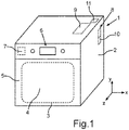
- FIG. 1 a schematic representation of a steamer 1 is shown.
- the steamer 1 has a housing 2 .
- a muffle 3 is arranged in the housing 2 . This delimits a cooking chamber 4 with its walls.
- the cooking chamber 4 is closed at the front by a door 5 of the steamer 1 . This is in 1 shown in closed condition.
- the steam cooking appliance 1 can also have an operating and/or display device 6 .
- the steam cooking appliance 1 can have a control unit 7 .
- the steamer 1 has a steam generating device or a steam generating system 8 . This is arranged in the housing 2 . It is arranged outside of the cooking space 4 . In particular, it can be arranged in an intermediate space between the housing 2 and the muffle 3 .
- the steam generation system 8 is arranged behind the muffle 3 in the depth direction (z-direction).
- the steamer 1 also has a separate tank 9 .
- the tank 9 is arranged in the housing 2 . It is arranged in a space between the housing 2 and the muffle 3 . Viewed in the height direction (y-direction) of the steam cooking appliance 1 , the tank 9 is arranged completely above a fluid line container 10 of the steam generation system 11 .
- This tank 9 is fluidly connected by lines to the liquid container 10 spaced therefrom.
- a fluid line is formed from the tank 9 to the liquid container 10 on the basis of gravity. This means that the liquid, in particular the water, flows from the tank 9 to the liquid container 10 purely on the basis of gravity.
- a pump is not provided in this regard.
- the steamer 1 has a pump 11 .
- the pump 11 is arranged in the housing 2 . In particular, it is arranged above the muffle 3 .
- the pump 11 is intended to convey liquid from the liquid container 10 to the tank 9 . In particular, the pump 11 is only intended and used to convey the liquid from the liquid container 10 to the tank 9 .
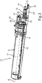
- FIG. 2 a partial detail of the steamer 1 is shown in an enlarged view.
- the housing 2 is not shown here.
- the interior of the housing 2 is therefore viewed.
- other device components are arranged above a muffle 3 (not shown).
- It can be a ventilation shaft 12, for example.
- a support plate 13 is provided for this purpose.
- the pump 11 can be arranged, in particular fastened, on this support plate 13 .
- the tank 9 can be arranged on this support plate 13 .
- the steam generation system 8 is shown.
- the liquid container 10 is shown here.
- an evaporator 14 of the vapor generation system 8 is shown.
- a vapor separator 15 of the vapor generation system 8 is shown in the exemplary embodiment.
- the tank 9 has an outer housing 16 .
- an inner housing 17 of the tank 9 is arranged therein.
- the liquid, in particular the water, is introduced directly into the inner housing 17 .
- the steamer 1 has a fluid line adapter 18 .
- the fluid line adapter 18 is coupled directly to the tank 9 .
- the steamer 1 has a coupling socket 19 . This is directly connected to the fluid line adapter 18 .
- the tank 9 is indirectly fluidly connected to the liquid container 10 via the fluid line adapter 18 .
- the coupling piece 19 is connected directly to an inlet 21 of the liquid container 10 by a line 20 .
- an outlet 22 of the liquid container 10 is connected to the pump 11 by a line 23 .
- the pump 11 is also connected in a fluid-conducting manner to the fluid line adapter 18 by a line 24 with an adapter inlet 25 .
- the tank 9 has a ventilation nozzle 26 . Air in the tank 9, in particular in the inner housing 17, can easily escape via this.
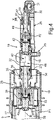
- FIG. 3 a perspective view of an arrangement 27 is shown.
- This has the tank 9 , the fluid line adapter 18 and the coupling piece 19 .
- the fluid line adapter 18 is directly coupled to the tank 9 with a push-pull system 28 .
- the outer housing 16 is connected directly to a support base 29 .
- the coupling socket 19 is arranged in a stationary manner on the carrier base 29 .
- the carrier base 29 is arranged directly on the device component, in particular the carrier plate 13 .
- a movable attachment can be provided for this purpose.
- the carrier base 29 can have a slot 31 on a base 30 .
- a fastening unit for example a screw, can be passed through this elongated hole 31 .
- a displacement movement of the carrier base 29 relative to the carrier plate 13 can be made possible through the elongated hole 31 .
- the carrier base 29 is connected to the outer housing 16 in a movement-coupled manner, a displacement movement of the outer housing 16 can also cause a corresponding displacement of the carrier base 29 .
- the push-pull system 28 can be positioned in particular at least the outer housing 16 of the tank 9 in at least two different positions along a longitudinal axis A.
- the longitudinal axis A is here both the longitudinal axis of the tank 9. It can be a longitudinal axis that runs parallel to a longitudinal axis of the fluid line adapter 18.
- this longitudinal axis A also runs parallel to a longitudinal axis B of the coupling piece 19.
- the tank 9, the fluid line adapter 18 and the coupling piece 9 are thus arranged in series along this longitudinal axis.
- an adapter outer housing 32 of the fluid line adapter 18 is arranged or mounted so that it can move relative to the outer housing 16 and the carrier base 29 between the tank 9 and the coupling socket 19 . Therefore, if the position of the tank 9, in particular the outer housing 16, is adjusted along the longitudinal axis A, this also leads in particular to a corresponding displacement of the carrier base 29 with the coupling piece 19 arranged stationary thereon.
- the coupling piece 19 is mounted in the adapter outer housing 32 so that it can move relatively .
- a relative movement is then also carried out in the outer adapter housing 32 . Because of these relative movement possibilities, a first fluid line path in the fluid line adapter 18 or a different second fluid line path in the fluid line adapter 18 is then automatically released or blocked.
- the longitudinal axis B of the fluid line adapter 18 is also shown. In the exemplary embodiment, this is also the longitudinal axis of the coupling socket 19.
- the adapter outer housing 32 is in 3 drawn in dashed lines and thus indicated transparently, so that the inner workings of the fluid line adapter 18 can be seen.
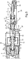
- FIG. 12 is a horizontal sectional view through the arrangement 27 according to FIG 3 shown in the area of the fluid line adapter 18 and the coupling piece 19 .
- the sectional plane is formed by the depth direction and the width direction (x-direction) of the steamer 1 .
- the tank 9 has a line socket 33 .
- the fluid line adapter 18 has an insertion socket 34 .
- this insertion socket 34 is arranged in a stationary manner in the outer adapter housing 32 . It is arranged at the end in such a way that it extends out of the adapter outer housing 32 .
- the insertion socket 34 is installed in a stationary manner in the adapter outer housing 32 .
- radial connecting elements 35 engage in a recess 36 in the jacket wall of the outer housing 32 .
- a seal 37 can be provided, with which the interface between the inside of the adapter outer housing 32 and the insertion socket 34 is sealed.
- the insertion socket 34 is coupled into the line socket 33 .
- a state is shown in which the tank 9, in particular the outer housing 16, is arranged in an end position.
- this is a first displacement position.
- a first fluid line path 40 of the fluid line adapter 18 is automatically released. This means that liquid can flow on this first, predefined fluid line path 40 into the coupling piece 19 and from there into the in 4 not shown line 20 can flow.
- the relevant principle of gravity enables this flow of the fluid.
- a specific relative position between the outer housing 16, the fluid line adapter 18 and the coupling piece 19 is set here in the direction of the longitudinal axes A and B.
- the coupling piece 19 protrudes into the adapter outer housing 32 and is movably mounted therein along the longitudinal axis B.
- a relative movement between the coupling piece 19 and the adapter outer housing 32 is thus made possible in this regard.
- the fluid then flows through the fluid line adapter 18 along the illustrated arrows P2 on this first fluid line path 40 .
- the outer adapter housing 32 is more or less pushed into the outer housing 16 than in 4 .
- the coupling stub 19 protrudes in the position in figure 5 further out of an adapter outlet 41 of the fluid line adapter 18, in particular of the adapter outer housing 32, than in the state in 4 . This therefore means that with this linear displacement of the outer housing 16 relative to the fluid line adapter 18 there is also automatically a relative displacement of the coupling socket 19 relative to the fluid line adapter 18 .
- the first fluid line path 40 in the fluid line adapter 18 is automatically blocked.
- no fluid is conveyed from the liquid container 10 back to the tank 9.
- the line 22 is filled and in the filled state, when the outlet 22 is closed, no more water can flow through, the complete flow on the first fluid line path 40 is made possible. That this second fluid line path 44 then in accordance with this state 4 is also open up to the closed exit 22 is then irrelevant.
- the plunger 42 sits in this closed position with a seal 45 on a stop 46, which is formed inside the adapter outer housing 32, firmly.
- This partial path 46 is both a component of the first fluid line path 40 and, at the same time, a component of the second fluid line path 44.
- a bidirectional Conducting the fluid from the tank 9 and into the tank 9 allows.
- this also shows the corresponding positional difference between the outer housing 16 and the fluid line adapter 18 .
- the adapter inlet 26 is connected to the liquid container 10 via a second line path 49
- the adapter outlet 41 is connected to the liquid container 10 via a first line path 48 .
- the first conduction path 48 and the second conduction path 49 are in 2 symbolically marked.
- the fluid line adapter 18 forms a structural unit. This has the adapter outer housing 32 in which the fluid line paths 40 and 44 are formed.
- the first fluid line path 40 is part of a gravity fluid line path, which is formed in particular by the first line path 48 .
- the second fluid line path 44 is part of a pump fluid line path, which is formed in particular by the second line path 49 .
- the tank 9 can be completely removed from the housing 2 . In this regard, it can then be filled externally with water. This also improves the cleanability.
Abstract
Die Erfindung betrifft ein Dampfgargerät (1) mit einem Gehäuse (2), mit einem Dampferzeugungssystem (8), dass in dem Gehäuse (2) angeordnet ist und welches Dampf erzeugt, der in einem Garraum (4) zum Zubereiten von Lebensmitteln nutzbar ist, und mit einem zum Dampferzeugungssystem (8) separaten Tank (9), so dass Flüssigkeit vom Tank (9) zu einem damit fluidleitend verbundenen Flüssigkeitsbehälter (10) aufgrund der Schwerkraft fließt, und mit einer Pumpe (11), mit welcher Flüssigkeit vom Flüssigkeitsbehälter (10) zum Tank (9) förderbar ist, wobei das Dampfgargerät (1) einen Fluidleitungsadapter (18) aufweist, wobei der Fluidleitungsadapter (18) einen ersten internen Fluidleitungsweg (40) aufweist, mit welchem Flüssigkeit von dem Leitungsstutzen (33) durch den Fluidleitungsadapter (18) zu einem Koppelstutzen (19) des Dampfgargeräts (1) leitbar ist, und der Fluidleitungsadapter (18) einen zweiten internen Fluidleitungsweg (44) aufweist, mit welchem Flüssigkeit von einem zum Adapterausgang (41) unterschiedlichen Adaptereingang (26) des Fluidleitungsadapters (18) zum Leitungsstutzen (33) leitbar ist.The invention relates to a steam cooking appliance (1) with a housing (2), with a steam generation system (8) which is arranged in the housing (2) and which generates steam which can be used in a cooking space (4) for preparing food. and with a tank (9) separate from the vapor generation system (8) so that liquid flows from the tank (9) to a liquid container (10) fluidly connected thereto by gravity, and with a pump (11) with which liquid from the liquid container ( 10) can be conveyed to the tank (9), the steam cooking appliance (1) having a fluid line adapter (18), the fluid line adapter (18) having a first internal fluid line path (40), with which liquid from the line socket (33) through the fluid line adapter (18) to a coupling socket (19) of the steamer (1) can be routed, and the fluid line adapter (18) has a second internal fluid line path (44) with which liquid from one to the adapter outlet (41) different adapter input (26) of the fluid line adapter (18) to the line socket (33) can be routed.
Description
Ein Aspekt der Erfindung betrifft ein Dampfgargerät gemäß dem Oberbegriff des Anspruchs 1.One aspect of the invention relates to a steam cooking appliance according to the preamble of
Dampfgargeräte weisen üblicherweise ein Dampferzeugungssystem auf. Mittels diesem wird aus einer Flüssigkeit, insbesondere Wasser, mittels eines Verdampfers des Dampferzeugungssystems Dampf erzeugt, der dann in den Garraum eingebracht werden kann. Mit dem Dampf kann das Zubereiten von Lebensmitteln in dem Garraum durchgeführt werden. Dampferzeugungssysteme können unterschiedlich aufgebaut sein. So sind diesbezüglich Geräte bekannt, die außerhalb des Garraums ein entsprechendes System aufweisen. Dieses kann üblicherweise einen Verdampfer, einen Dampfabscheider und einen Flüssigkeitsbehälter aufweisen.Steam cooking appliances usually have a steam generation system. This is used to generate steam from a liquid, in particular water, by means of an evaporator of the steam generation system, which steam can then be introduced into the cooking chamber. The steam can be used to prepare food in the cooking chamber. Steam generation systems can be constructed in different ways. Devices are known in this regard that have a corresponding system outside the cooking chamber. This can usually have an evaporator, a vapor separator and a liquid container.
Darüber hinaus sind auch Systeme bekannt, die zusätzlich zu dieser Konfiguration einen weiteren separaten Tank aufweisen. Dieser Tank ist zur externen Befüllung vorgesehen. Ein derartiger weiterer separater Tank kann aus dem Gehäuse des Dampfgargeräts entnommen werden, um ihn extern zum Gerät mit Wasser zu befüllen. Bei derartigen Ausgestaltungen ist der separate Tank über Leitungen mit dem Fluidleitungsbehälter des Dampferzeugungssystems verbunden. Beispielsweise kann dann mittels einer Pumpe des Dampfgargeräts Wasser vom Tank zum Flüssigkeitsbehälter des Dampferzeugungssystems geleitet werden. Mit einer dazu unterschiedlichen zweiten Pumpe kann Restflüssigkeit im Fluidleitungsbehälter zurück zum Tank gepumpt werden. Derartige Systeme sind komponentenintensiv und benötigen zwei separate Pumpen.In addition, systems are also known which have a further separate tank in addition to this configuration. This tank is intended for external filling. Such a further separate tank can be removed from the housing of the steam cooking appliance in order to fill it with water externally to the appliance. In such configurations, the separate tank is connected to the fluid line container of the steam generation system via lines. For example, water can then be conducted from the tank to the liquid container of the steam generation system by means of a pump of the steam cooking appliance. With a different second pump, residual liquid in the fluid line container can be pumped back to the tank. Such systems are component intensive and require two separate pumps.
Bekannt ist es auch, dass bei oben genannten Ausführungen die Zuleitung des Wassers vom Tank zum Fluidleitungsbehälter des Dampferzeugungssystems auf Basis der Schwerkraft erfolgt. Dadurch kann beispielsweise eine Pumpe eingespart werden.It is also known that in the above-mentioned embodiments, the water is fed from the tank to the fluid line container of the steam generation system on the basis of gravity. As a result, a pump can be saved, for example.
Derartiges ist beispielsweise aus der
Es ist Aufgabe der vorliegenden Erfindung, ein Dampfgargerät zu schaffen, bei welchem gerade bei einer bidirektionalen Fluidleitung von einem Tank zu einem Flüssigkeitsbehälter des Dampferzeugungssystems die jeweiligen Betriebszustände des gerichteten Leitens verbessert sind.It is the object of the present invention to create a steam cooking appliance in which the respective operating states of the directed conduction are improved, particularly in the case of a bidirectional fluid line from a tank to a liquid container of the steam generation system.
Diese Aufgabe wird durch ein Dampfgargerät, welches die Merkmale nach Anspruch 1 aufweist, gelöst.This object is achieved by a steamer having the features of
Ein Aspekt der Erfindung betrifft ein Dampfgargerät mit einem Gehäuse. Das Dampfgargerät weist darüber hinaus einen Garraum auf. Dieser ist in dem Gehäuse ausgebildet. Das Dampfgargerät weist darüber hinaus ein Dampferzeugungssystem auf. Das Dampferzeugungssystem ist in dem Gehäuse angeordnet. Das Dampferzeugungssystem ist bestimmungsgemäß dazu vorgesehen, aus Flüssigkeit Dampf zu erzeugen. Dieser ist zum Einbringen in den Garraum vorgesehen, um damit Lebensmittel zuzubereiten. Das Dampferzeugungssystem weist einen separaten Tank auf. Dieser ist insbesondere bestimmungsgemäß dazu vorgesehen, dass er extern zum Dampfgargerät mit Flüssigkeit füllbar ist. Der Tank ist in dem Gehäuse angeordnet. In Höhenrichtung des Dampfgargeräts betrachtet, ist der Tank, insbesondere vollständig, höherliegend angeordnet, als ein Flüssigkeitsbehälter des Dampferzeugungssystems. Der Flüssigkeitsbehälter ist ein zum Tank separater Behälter. Durch diese höhenversetzte Anordnung zwischen dem Tank und dem Flüssigkeitsbehälter kann Flüssigkeit vom Tank zum damit fluidleitend verbundenen Flüssigkeitsbehälter aufgrund der Schwerkraft fließen. Es ist also mit dieser Fließrichtung ein Konzept realisiert, bei dem bestimmungsgemäß keine Pumpe vorgesehen ist. Lediglich auf Basis des Schwerkraftprinzips fließt diese Flüssigkeit in diese Richtung vom Tank zum Flüssigkeitsbehälter. Das Dampfgargerät weist darüber hinaus eine Pumpe auf. Diese ist bestimmungsgemäß dazu vorgesehen, Flüssigkeit vom Flüssigkeitsbehälter zum Tank zu fördern. Die Pumpe ist also insbesondere nur dazu vorgesehen, die Flüssigkeit in diese eine Fließrichtung, nämlich vom Flüssigkeitsbehälter zum Tank, zu fördern. Das Dampfgargerät weist darüber hinaus einen Fluidleitungsadapter auf. Der Tank weist einen Leitungsstutzen auf. Dieser Fluidleitungsadapter ist direkt mit diesem Leitungsstutzen des Tanks gekoppelt. Der Fluidleitungsadapter und der Leitungsstutzen sind diesbezüglich separate Komponenten. Sie können zerstörungsfrei lösbar gekoppelt und entkoppelt werden. Der Fluidleitungsadapter weist einen ersten, internen Fluidleitungsweg auf, über welchen Flüssigkeit von dem Leitungsstutzen durch den Fluidleitungsadapter zu einem Koppelstutzen des Dampfgargeräts leitbar ist. Insbesondere ist dieses Leiten vollzogen, wenn ein diesbezüglich erster Betriebszustand des Fluidleitungsadapters eingestellt ist. Der Koppelstutzen ist bewegbar an einem Adapterausgang des Fluidleitungsadapters angeordnet. Darüber hinaus ist der Koppelstutzen auf einem ersten Leitungsweg, der sich zwischen dem Tank und dem Flüssigkeitsbehälter bemisst, fluidleitend mit dem Fluidleitungsbehälter verbunden. Der Fluidleitungsadapter weist einen zweiten, zumindest teilweise zum ersten unterschiedlichen, internen Fluidleitungsweg auf, mit welchem Flüssigkeit von einem zum Adapterausgang des Fluidleitungsadapters unterschiedlichen Adaptereingang des Fluidleitungsadapters zum Leitungsstutzen leitbar ist. Insbesondere ist diese Leiten vollzogen, wenn ein zweiter Betriebszustand der Fluidleitungsadapters eingestellt ist. Der Adaptereingang ist auf einem zum ersten Leitungsweg separaten zweiten Leitungsweg fluidleitend mit dem Flüssigkeitsbehälter verbunden. Bei dem Dampfgargerät ist es also vorgesehen, durch eine ganz spezifische Komponente, nämlich den Fluidleitungsadapter, die bidirektionale Fluidleitung vom Tank zum Flüssigkeitsbehälter zu verbessern. Dieser Fluidleitungsadapter ermöglicht es diesbezüglich quasi als einzige Komponente, dennoch die jeweiligen Fließwege individuell einzustellen und somit freizugeben und zu sperren. Es kann somit ein hochfunktionelles Konzept bereitgestellt werden. Dieses ist sowohl platzsparend als auch bauteilsparend realisiert. Durch den Fluidleitungsadapter können die einzelnen Fließwege individuell freigegeben und gesperrt werden und diesbezüglich auch sehr definiert und präzise ermöglicht werden. Unerwünschte Leckagen können dadurch vermieden werden. Dadurch ist gerade bei dieser Konfiguration, bei der nicht zwei Pumpen für jeweils einen der Fließwege vorgesehen sind, sondern einerseits nur das Schwerkraftprinzip realisiert werden soll und andererseits nur mit einer Pumpe die Rückförderung erfolgen soll, eine deutliche Verbesserung erzielt. Unerwünscht auftretende Rückströmungen oder Überströmungen zwischen den Fluidleitungswegen können dadurch vermieden werden. Die Möglichkeit, dass eine Relativbewegung zwischen dem Koppelstutzen und dem Fluidleitungsadapter ermöglicht ist, trägt auch vorteilhaft zum einfachen, schnellen und hochfunktionellen Umschalten zwischen den beiden internen Fluidleitungswegen bei. Darüber hinaus kann durch diese Ausgestaltung auch die sichere Bewegung des Fluidleitungsadapters ermöglicht werden. Insbesondere ist er durch diese Konfiguration quasi zwischen dem Tank und dem Koppelstutzen bewegbar, insbesondere linear verschiebbar, gelagert.One aspect of the invention relates to a steam cooking appliance with a housing. The steamer also has a cooking chamber. This is formed in the housing. The steam cooking appliance also has a steam generation system. The steam generation system is arranged in the housing. The vapor generation system is intended to generate vapor from liquid. This is intended to be placed in the cooking chamber in order to prepare food with it. The steam generation system has a separate tank. This is intended in particular to be filled with liquid externally to the steamer. The tank is arranged in the housing. Viewed in the vertical direction of the steam cooking appliance, the tank, in particular in its entirety, is arranged higher than a liquid container of the steam generation system. The liquid tank is a separate tank from the tank. Due to this height-staggered arrangement between the tank and the liquid container, liquid can flow from the tank to the liquid container connected to it due to gravity. With this direction of flow, a concept is thus realized in which no pump is intended to be provided. Based solely on the principle of gravity, this liquid flows in this direction from the tank to the liquid container. The steamer also has a pump. This is intended to convey liquid from the liquid container to the tank. In particular, the pump is therefore only intended to convey the liquid in this one direction of flow, namely from the liquid container to the tank. The steamer also has a fluid line adapter. The tank has a line socket. This fluid line adapter is coupled directly to this line connector of the tank. The fluid line adapter and the line connector are separate components in this regard. They can be detachably coupled and decoupled non-destructively. The fluid line adapter has a first, internal fluid line path via which liquid can be routed from the line socket through the fluid line adapter to a coupling socket of the steam cooking appliance. In particular, this conduction is completed when a first operating state of the fluid line adapter in this respect is set. The coupling piece is movably arranged on an adapter outlet of the fluid line adapter. In addition, the coupling piece is connected in a fluid-conducting manner to the fluid line container on a first line path, which is measured between the tank and the liquid container. The fluid line adapter has a second internal fluid line path, at least partially different from the first, with which liquid can be routed from an adapter inlet of the fluid line adapter, which is different from the adapter outlet of the fluid line adapter, to the line connector. In particular, this routing is completed when a second operating state of the fluid line adapter is set. The adapter inlet is fluidly connected to the liquid container on a second line path, which is separate from the first line path. In the case of the steam cooking appliance, it is therefore intended to improve the bidirectional fluid line from the tank to the liquid container by means of a very specific component, namely the fluid line adapter. In this regard, this fluid line adapter is virtually the only component that makes it possible to set the respective flow paths individually and thus to release and block them. A highly functional concept can thus be provided. This is implemented in a way that saves both space and components. Through the fluid line adapter, the individual flow paths can be released and blocked individually and in this respect also made possible in a very defined and precise manner. Undesirable leaks can be avoided in this way. As a result, a clear improvement is achieved precisely in this configuration, in which two pumps are not provided for each of the flow paths, but on the one hand only the principle of gravity is to be implemented and on the other hand only one pump is to be used for return delivery. Undesirably occurring backflows or overflows between the fluid line paths can thereby be avoided. The possibility that a relative movement between the coupling piece and the fluid line adapter is made possible also advantageously contributes to the simple, fast and highly functional switching between the two internal fluid line paths. In addition, the safe movement of the fluid line adapter can also be made possible by this configuration. In particular, due to this configuration, it can be moved, in particular linearly displaceably, as it were between the tank and the coupling piece.
Dazu kann in einem Ausführungsbeispiel vorgesehen sein, dass der Tank und der Fluidleitungsadapter sowie der Koppelstutzen in linearer Reihenfolge zueinander angeordnet sind. Eine einfache axiale Bewegung des Fluidleitungsadapters relativ zu dem damit gekoppelten Koppelstutzen ermöglicht einen einfachen Verschiebeweg. Dieser trägt ebenso positiv dazu bei, dass die entsprechende Umstellung zwischen den internen Fluidleitungswegen hochfunktionell ist. Nicht zuletzt ist es dadurch auch ermöglicht, dass der Fluidleitungsadapter relativ bewegbar zu zumindest einer Komponente des Tanks verbunden ist. Insbesondere ist diesbezüglich eine Relativbewegung des Fluidleitungsadapters zu einem Außengehäuse des Tanks möglich. Dadurch kann auch der Tank in unterschiedlichen Betriebsstellungen positioniert werden. Diesbezüglich können sich dann auch unterschiedliche Positionierungen zum Fluidleitungsadapter ergeben. Auch dadurch lässt sich eine einfache Einstellung der Positionen der genannten Komponenten zueinander erreichen. Dies führt wiederum dazu, dass auch automatisch abhängig davon die internen Fluidleitungswege des Fluidleitungsadapters hochpräzise freigegeben oder gesperrt werden können.For this purpose it can be provided in one exemplary embodiment that the tank and the fluid line adapter as well as the coupling socket are arranged in a linear sequence relative to one another. A simple axial movement of the fluid line adapter relative to the coupling piece coupled to it enables a simple displacement path. This also contributes positively to the fact that the corresponding changeover between the internal fluid line paths is highly functional. Last but not least, this also makes it possible for the fluid line adapter to be connected to at least one component of the tank in a relatively movable manner. In particular, a relative movement of the fluid line adapter to an outer housing of the tank is possible in this respect. This also allows the tank to be positioned in different operating positions. In this regard, different positions can then also result in relation to the fluid line adapter. This also makes it possible to easily adjust the positions of the components mentioned in relation to one another. This in turn means that the internal fluid line paths of the fluid line adapter can also be released or blocked automatically depending on this with high precision.
Durch die spezifische Kopplung zwischen den Tank, dem Fluidleitungsadapter und dem Koppelstutzen können durch einfache Verschiebungen die gewünschten positionellen Änderungen erreicht werden, die dann die Fließwege freigeben oder sperren.Due to the specific coupling between the tank, the fluid line adapter and the coupling piece, the desired positional changes can be achieved by simple displacements, which then release or block the flow paths.
In einem Ausführungsbeispiel bildet der Fluidleitungsadapter eine bauliche Einheit. Diese weist ein Adapteraußengehäuse auf, in dem die beiden Fluidleitungswege ausgebildet sind. Dieses Adapteraußengehäuse kann rohrartig ausgebildet sein. Dadurch ist es kompakt aufgebaut, kann aber dennoch die zusätzlichen erforderlichen Komponenten des Fluidleitungsadapters aufnehmen. Insbesondere ist diesbezüglich vorgesehen, dass dieses Adapteraußengehäuse eine Längsachse aufweist. Diese ist parallel oder koaxial zu einer Längsachse des Koppelstutzens orientiert. Insbesondere ist diese Längsachse des Adapteraußengehäuses parallel oder koaxial zur Längsachse des Tanks ausgebildet. Gerade auch diese Ausgestaltung unterstützt die vorteilhaften, oben genannten Relativbewegungsmöglichkeiten zwischen den genannten Komponenten zueinander. Lediglich durch eine einfache lineare Verschiebung können sich dadurch die individuellen Positionierungen der genannten Komponenten zueinander einfach einstellen lassen.In one embodiment, the fluid line adapter forms a structural unit. This has an adapter outer housing in which the two fluid line paths are formed. This adapter outer housing can be tubular. As a result, it is compact in design, but can still accommodate the additional required components of the fluid line adapter. In particular, it is provided in this respect that this adapter outer housing has a longitudinal axis. This is oriented parallel or coaxially to a longitudinal axis of the coupling piece. In particular, this longitudinal axis of the adapter outer housing is parallel or coaxial to the longitudinal axis of the tank. It is precisely this configuration that also supports the advantageous, above-mentioned possibilities of relative movement between the components mentioned. The individual positioning of the named components in relation to one another can be easily adjusted merely by means of a simple linear displacement.
In einem Ausführungsbeispiel ist der erste Fluidleitungsweg Bestandteil eines Schwerkraft-Fluidleitungswegs als Leitungsweg zwischen dem Tank und dem Flüssigkeitsbehälter. In einem Ausführungsbeispiel ist der erste Fluidleitungsweg Bestandteil eines Schwerkraft-Fluidleitungswegs, der sich zwischen dem Tank und dem Flüssigkeitsbehälter erstreckt. Der zweite Fluidleitungsweg ist Bestandteil eines Pumpen-Fluidleitungswegs als weiteren Leitungsweg, der sich zwischen dem Flüssigkeitsbehälter und dem Tank erstreckt.In one embodiment, the first fluid conduit is part of a gravity fluid conduit as a conduit between the tank and the liquid container. In one embodiment, the first fluid pathway is part of a gravity fluid pathway that extends between the tank and the liquid container. The second fluid line path is part of a pump fluid line path as another line path that extends between the liquid container and the tank.
In einem Ausführungsbeispiel ist ein Teilweg für Fluid im Fluidleitungsadapter, der am Leitungsstutzen beginnt, sowohl Bestandteil des ersten Fluidleitungswegs als auch des zweiten Fluidleitungswegs. Auch dadurch kann der kompakte Aufbau des Fluidleitungsadapters unterstützt werden. Durch eine geschickte Gestaltung dieser Fluidleitungswege im Außengehäuse des Fluidleitungsadapters selbst kann auch hier entsprechend Platz gespart werden. Indem hier ein Teilweg für beide Fluidleitungswege genutzt wird, kann die Kompaktheit des gesamten Fluidleitungsadapters nochmal verbessert werden. Darüber hinaus ist es dann ermöglicht, dass der Fluidleitungsadapter lediglich an einer Koppelstelle direkt mit dem Leitungsstutzen des Tanks verbunden ist. Es bedarf daher an der Schnittstelle zwischen dem Fluidleitungsadapter und dem Tank lediglich dieses einen Leitungsstutzens und des Gegenstutzens des Fluidleitungsadapters, um diesen Teilweg bereitzustellen. An der Schnittstelle zwischen dem Fluidleitungsadapter und dem Tank müssen daher keine zwei separaten Stutzen bereitgestellt werden, die für die beiden Fluidleitungswege individuell und separat vorgesehen wären.In one embodiment, a partial path for fluid in the fluid line adapter, which starts at the line socket, is part of both the first fluid line path and the second fluid line path. This can also support the compact design of the fluid line adapter. A clever design of these fluid line paths in the outer housing of the fluid line adapter itself can also save space accordingly. By using a partial path for both fluid line paths here, the compactness of the entire fluid line adapter can be improved again. In addition, it is then possible for the fluid line adapter to be connected directly to the line socket of the tank at only one coupling point. It is therefore only necessary at the interface between the fluid line adapter and the tank to provide this partial path. At the interface between the fluid line adapter and the tank, it is therefore not necessary to provide two separate sockets that would be provided individually and separately for the two fluid line paths.
In einem Ausführungsbeispiel ist der Koppelstutzen in dem Adaptergehäuse axial verschiebbar gelagert. Er erstreckt sich in allen Verschiebestellungen beidseits des Adapterausgangs. Die Bewegbarkeit des Koppelstutzens relativ zu dem Adaptergehäuse ist allgemein zu betrachten. Dies bedeutet auch, dass der Koppelstutzen relativ zum Adaptergehäuse bewegt wird und somit dieser Koppelstutzen das sich bewegende Teil ist. In einem anderen Ausführungsbeispiel ist es vorzugsweise vorgesehen, dass das Adapteraußengehäuse bewegt wird und dadurch die Relativbewegung zwischen dem Koppelstutzen und dem Adapteraußengehäuse gebildet ist. Auch diese Anordnung des Koppelstutzens, der sich aus dem Adapterausgang des Adapteraußengehäuses heraus erstreckt, ist auch eine einfache Verbindung dieses Koppelstutzens mit einer Leitung ermöglicht. Die Leitung führt dann von dem Koppelstutzen zu dem Flüssigkeitsbehälter des Dampferzeugungssystems. Darüber hinaus ist durch diese beidseitige Erstreckung genau diese Schnittstelle zwischen dem Koppelstutzen und der daran direkt angeordneten Leitung nicht beeinträchtigt, wenn sich eine Relativbewegung zwischen dem Koppelstutzen und dem Adapteraußengehäuse ergibt. Unerwünschte Beeinträchtigungen der Leitung können dadurch vermieden werden.In one embodiment, the coupling piece is mounted in the adapter housing in an axially displaceable manner. It extends in all displacement positions on both sides of the adapter outlet. The mobility of the coupling piece relative to the adapter housing is to be considered in general terms. This also means that the coupling piece is moved relative to the adapter housing and thus this coupling piece is the moving part. In another exemplary embodiment, it is preferably provided that the outer adapter housing is moved and the relative movement between the coupling socket and the outer adapter housing is thereby formed. This arrangement of the coupling piece, which extends out of the adapter outlet of the adapter outer housing, is also a simple connection of this coupling piece to a line allows. The line then leads from the coupling piece to the liquid container of the vapor generation system. In addition, due to this extension on both sides, precisely this interface between the coupling piece and the line arranged directly on it is not impaired if there is a relative movement between the coupling piece and the outer adapter housing. Undesirable impairments of the line can be avoided in this way.
In einem Ausführungsbeispiel weist der Koppelstutzen zumindest eine Dichtung auf. Dadurch ist der Ausgang des Adapteraußengehäuses durch diesen Koppelstutzen auch abgedichtet. Unerwünschter Flüssigkeitsaustritt aus dem Adapteraußengehäuse an diesem Adapterausgang kann dadurch ebenfalls vermieden werden. Dennoch kann die Relativbewegung zwischen dem Koppelstutzen und dem Adapteraußengehäuses sicher erreicht werden.In one embodiment, the coupling piece has at least one seal. As a result, the outlet of the adapter outer housing is also sealed off by this coupling piece. Undesirable leakage of liquid from the adapter outer housing at this adapter outlet can also be avoided as a result. Nevertheless, the relative movement between the coupling piece and the adapter outer housing can be reliably achieved.
In einem Ausführungsbeispiel ist der Koppelstutzen ortsfest an einem Trägersockel des Dampfgargeräts angeordnet. Der Trägersockel ist ein zum Adapteraußengehäuse des Fluidleitungsadapters separates Bauteil. Durch eine derartige Ausgestaltung kann der Koppelstutzen mechanisch fest und stabil angeordnet werden. Der Trägersockel ist in dem Zusammenhang ein stabiler Träger für diesen Koppelstutzen. Mechanische Kräfte, die bei den oben genannten Relativbewegungsmöglichkeiten auftreten, können dann durch den Trägersockel einfach aufgenommen und abgeleitet werden. Der Trägersockel kann in dem Zusammenhang an einem weiteren Bauteil des Dampfgargeräts beziehungsweise einer Gerätekomponente des Dampfgargeräts angeordnet sein. Beispielsweise kann dies eine Horizontalwand des Dampfgargeräts sein. Der Träger des Sockels kann somit von oben auf diese Horizontalwand aufgebracht sein. Er kann diesbezüglich mit dieser dazu separaten Horizontalwand verbunden sein.In one embodiment, the coupling piece is arranged in a stationary manner on a support base of the steamer. The support base is a component that is separate from the adapter outer housing of the fluid line adapter. With such a configuration, the coupling piece can be arranged mechanically firmly and stably. In this context, the carrier base is a stable carrier for this coupling socket. Mechanical forces that occur with the relative movement options mentioned above can then be easily absorbed and dissipated by the carrier base. In this context, the support base can be arranged on a further component of the steamer or a device component of the steamer. For example, this can be a horizontal wall of the steamer. The support of the base can thus be applied to this horizontal wall from above. In this regard, it can be connected to this horizontal wall, which is separate therefrom.
Beispielsweise kann die Horizontalwand eine Deckenwand sein. Diese kann zwischen einer Deckenwand des Außengehäuses des Dampfgargeräts und einer Deckenwand einer Muffel des Dampfgargeräts, die den Garraum begrenzt, angeordnet sein. Sie kann Bestandteil eines Lüftungskanals des Dampfgargeräts sein.For example, the horizontal wall can be a ceiling wall. This can be arranged between a top wall of the outer housing of the steamer and a top wall of a muffle of the steamer, which delimits the cooking space. It can be part of a ventilation duct of the steamer.
In einem Ausführungsbeispiel kann der Trägersockel fest mit einem dazu separaten Außengehäuse des Tanks verbunden sein. Diesbezüglich ist insbesondere eine Bewegungskopplung vorgesehen. Dies bedeutet dann beispielsweise auch, dass in einem Ausführungsbeispiel, in dem das Außengehäuse des Tanks verschiebbar ist, auch der Trägersockel diesbezüglich bewegungsgekoppelt verschiebbar ist. Dadurch ist ein besonders vorteilhaftes Konzept erreicht, um Relativverschiebungen zwischen dem Koppelstutzen und dem Fluidleitungsadapter zu erreichen. Dies ist dadurch ermöglicht, dass der Fluidleitungsadapter, der zwischen dem Außengehäuse des Tanks und dem Koppelstutzen angeordnet ist, durch diese mechanische Verbindung des Außengehäuses des Tanks und des Trägersockels besonders vorteilhaft relativ verschiebbar gelagert ist. Die besonders stabile mechanische Lagerung des Fluidleitungsadapters in Reihe zwischen den genannten Komponenten ist dadurch ermöglicht. Eine besonders präzise und geradlinige Verschiebung zwischen den Komponenten ist dadurch erreicht.In one embodiment, the support base can be firmly connected to a separate outer housing of the tank. In this regard, one in particular Movement coupling provided. This then also means, for example, that in an exemplary embodiment in which the outer housing of the tank can be displaced, the support base can also be displaced in a motion-coupled manner in this respect. As a result, a particularly advantageous concept is achieved in order to achieve relative displacements between the coupling piece and the fluid line adapter. This is made possible by the fact that the fluid line adapter, which is arranged between the outer housing of the tank and the coupling piece, is particularly advantageously mounted in a relatively displaceable manner by this mechanical connection of the outer housing of the tank and the support base. This enables the particularly stable mechanical mounting of the fluid line adapter in series between the components mentioned. A particularly precise and linear displacement between the components is thereby achieved.
In einem Ausführungsbeispiel ist der Trägersockel bewegbar an der bereits oben genannten Gerätekomponente angeordnet. Insbesondere weist der Trägersockel ein Langloch in einer Sockelbasis auf, so dass durch das Langloch ein linearer Bewegungsweg des Trägersockels vorgegeben ist. Dies ist dahingehend vorteilhaft, dass der Trägersockel einerseits direkt an einer weiteren Gerätekomponente angeordnet ist, andererseits die Bewegungskopplung mit dem Außengehäuse des Tanks gegeben ist und diesbezüglich auch eine gewisse Verschiebbarkeit des Trägersockels zur Gerätekomponente erreicht ist. Durch dieses Langloch ist darüber hinaus auch eine gewisse Führung für den Trägersockel vorgegeben. Die lineare Bewegungsmöglichkeit des Trägersockels ist dadurch nochmals verbessert.In one embodiment, the support base is movably arranged on the device component already mentioned above. In particular, the carrier base has a slot in a base base, so that a linear path of movement of the carrier base is specified by the slot. This is advantageous in that the support base is arranged directly on a further device component and the movement is coupled to the outer housing of the tank and the support base can also be moved to a certain extent relative to the device component. A certain amount of guidance for the carrier base is also provided by this elongated hole. This further improves the possibility of linear movement of the carrier base.
In einem Ausführungsbeispiel ist ein Außengehäuse des Tanks axial bewegbar angeordnet. Es kann vorgesehen sein, dass der Tank ein Außengehäuse und ein Innengehäuse aufweist. Das Innengehäuse ist diesbezüglich dasjenige Bauteil, in dem das Wasser direkt angeordnet ist. Es kann vorgesehen sein, dass das Außengehäuse relativ verschiebbar zum Innengehäuse angeordnet ist. Durch diese Möglichkeit kann das Außengehäuse positionell verändert werden. Da das Außengehäuse insbesondere dasjenige Bauteil ist, welches die Kopplung mit tankexternen Gerätekomponenten ermöglicht, kann dadurch der Tank, insbesondere das Außengehäuse in verschiedenen definierten Stellungen zu diesen Gerätekomponenten positioniert werden. Dadurch können sich auch definierte Positionen ergeben, die einerseits die Zwischenposition, andererseits eine Endposition definieren. In diesen definierten diskreten Positionen kann dann auch ein jeweiliger Betriebszustand charakterisiert sein, indem einerseits das schwerkraftbedingte Zuleiten von Wasser zum Flüssigkeitsbehälter freigegeben ist und das Zurückführen, insbesondere das Zurückpumpen vom Flüssigkeitsbehälter zum Tank gesperrt ist. Andererseits kann durch die Zwischenposition ein konkreter Zustand definiert sein, mit dem dann der zweite Fluidleitungsweg der Fluidleitungsadapter freigegeben ist.In one embodiment, an outer housing of the tank is arranged to be axially movable. It can be provided that the tank has an outer housing and an inner housing. In this regard, the inner housing is the component in which the water is arranged directly. Provision can be made for the outer housing to be arranged such that it can be displaced relative to the inner housing. With this possibility, the position of the outer housing can be changed. Since the outer housing is in particular that component which enables the coupling to tank-external device components, the tank, in particular the outer housing, can be positioned in various defined positions in relation to these device components. This can also result in defined positions, which on the one hand define the intermediate position and on the other hand an end position. In these defined discrete positions a respective operating state can then also be characterized in that, on the one hand, the gravitational supply of water to the liquid container is released and the return, in particular the pumping back from the liquid container to the tank, is blocked. On the other hand, a concrete state can be defined by the intermediate position, with which the second fluid line path of the fluid line adapter is then released.
Damit ist es in einem Ausführungsbeispiel sehr einfach möglich, dass nur durch die Positionsverstellung des Tanks, insbesondere dessen Außengehäuse, dann automatisch diejenige Position des Fluidleitungsadapters miteingestellt wird, die entweder den ersten Fluidleitungsweg oder den zweiten Fluidleitungsweg freigibt. Damit ist auch ein besonders einfaches Bedienkonzept bereitgestellt, um bedarfsgerecht auch manuell die individuellen Fluidleitungswege im Fluidleitungsadapter freizugeben oder zu sperren. Dies kann dann in diesem Ausführungsbeispiel durch einfache Verstellung des Tanks, insbesondere die lineare Verstellung des Außengehäuses, von der Endposition in die Zwischenposition oder von der Zwischenposition in die Endposition erreicht werden.In one exemplary embodiment, it is thus very easily possible for the position of the fluid line adapter that releases either the first fluid line path or the second fluid line path to be automatically set only by adjusting the position of the tank, in particular its outer housing. This also provides a particularly simple operating concept for manually releasing or blocking the individual fluid line paths in the fluid line adapter as required. In this exemplary embodiment, this can then be achieved by simply adjusting the tank, in particular the linear adjustment of the outer housing, from the end position to the intermediate position or from the intermediate position to the end position.
In einem Ausführungsbeispiel ist in einer ersten Verschiebestellung, der Endposition, des Außengehäuses des Tanks relativ zum Fluidleitungsadapter automatisch der erste Fluidleitungsweg im Fluidleitungsadapter freigegeben. In einer zweiten Verschiebestellung, der Zwischenposition, des Außengehäuses des Tanks relativ zum Fluidleitungsadapter ist automatisch der zweite Fluidleitungsweg im Fluidleitungsadapter freigegeben. Insbesondere ist der jeweils andere Weg dann automatisch gesperrt.In one exemplary embodiment, the first fluid line path in the fluid line adapter is automatically released in a first displacement position, the end position, of the outer housing of the tank relative to the fluid line adapter. In a second displacement position, the intermediate position, of the outer housing of the tank relative to the fluid line adapter, the second fluid line path in the fluid line adapter is automatically released. In particular, the other route is then automatically blocked.
Insbesondere ist die Verschiebebewegung des Koppelstutzens im Adapteraußengehäuse beziehungsweise die Relativbewegung zwischen dem Koppelstutzen und dem Adapteraußengehäuses mit der Verschiebebewegung des Außengehäuses des Tanks bewegungsgekoppelt. Sie führen also die gleiche Bewegung und/oder den gleichen Bewegungsweg durch.In particular, the displacement movement of the coupling piece in the adapter outer housing or the relative movement between the coupling piece and the adapter outer housing is movement-coupled to the displacement movement of the outer housing of the tank. They therefore carry out the same movement and/or the same movement path.
In einem Ausführungsbeispiel weist der Fluidleitungsadapter einen, insbesondere axial, bewegbaren Stößel auf. Dieser ist im Adapteraußengehäuse angeordnet. Der Stößel ist bestimmungsgemäß dazu vorgesehen, dass abhängig von dem Betriebszustand des Fluidleitungsadapters der erste Fluidleitungsweg freigegeben ist oder gesperrt ist.In one exemplary embodiment, the fluid line adapter has a tappet that can be moved, in particular axially. This is arranged in the adapter outer housing. The tappet is intended to be provided so that the first fluid line path is released or blocked depending on the operating state of the fluid line adapter.
In einem Ausführungsbeispiel weist der Fluidleitungsadapter eine Feder auf. Diese ist insbesondere mit dem Stößel gekoppelt. Der Stößel ist in einem Ausführungsbeispiel zum Sperren des ersten Fluidleitungswegs mit dieser Feder in axialer Richtung in eine Schließposition gedrückt. Dadurch ist ein Automatismus generiert, der bei der Relativbewegung zwischen dem Außengehäuse des Tanks, dem Fluidleitungsadapter und dem Koppelstutzen automatisch dieses Drücken in die Schließposition bedingt.In one embodiment, the fluid line adapter has a spring. This is particularly coupled to the ram. In one exemplary embodiment, the tappet is pressed into a closed position in the axial direction with this spring in order to block the first fluid line path. As a result, an automatism is generated which automatically causes this pressing into the closed position during the relative movement between the outer housing of the tank, the fluid line adapter and the coupling piece.
In einem Ausführungsbeispiel ist der Tank mit einer Push-Pull-Vorrichtung mit dem Fluidleitungsadapter gekoppelt. Dies ist ein hochfunktionelles Prinzip, welches andererseits ein schnelles Koppeln und Entkoppeln ermöglicht.In one embodiment, the tank is coupled to the fluid line adapter with a push-pull device. This is a highly functional principle, which on the other hand enables quick coupling and decoupling.
In einem Ausführungsbeispiel ist der Tank zum Befüllen mit Flüssigkeit, insbesondere Wasser, aus dem Gehäuse des Dampfgargeräts reversibel entnehmbar und wieder einsetzbar.In one exemplary embodiment, the tank can be reversibly removed from the housing of the steam cooking appliance and reinserted in order to be filled with liquid, in particular water.
In einem Ausführungsbeispiel ist vorgesehen, dass dann, wenn der zweite Fluidleitungsweg im Flüssigkeitsbehälter freigegeben ist, ein Schalter des Dampfgargeräts betätigt wird, bei welchem die Pumpe zum Rückführen der Flüssigkeit von dem Flüssigkeitsbehälter zum Tank aktiviert wird. Auch dann kann somit ein aktives automatisches Anschalten der Pumpe erreicht werden. Das Dampfgargerät weist eine Steuereinheit auf. Diese steuert den Vorgang.In one exemplary embodiment it is provided that when the second fluid line path in the liquid container is released, a switch of the steam cooking appliance is actuated, in which case the pump for returning the liquid from the liquid container to the tank is activated. Even then, an active automatic switching on of the pump can be achieved. The steam cooking appliance has a control unit. This controls the process.
Durch den Stößel im Fluidleitungsadapter mit einem Stößelsitz kann in einem Ausführungsbeispiel ein integriertes Ventil in dem Fluidleitungsadapter realisiert werden. Dadurch ist besonders vorteilhafterweise das Sperren und Freigeben des ersten Fluidleitungswegs im Fluidleitungsadapter ermöglicht. Insbesondere durch ein integriertes Ventil.In one exemplary embodiment, an integrated valve can be implemented in the fluid line adapter by the tappet in the fluid line adapter having a tappet seat. This particularly advantageously enables the first fluid line path to be blocked and released in the fluid line adapter. Especially with an integrated valve.
Insbesondere ist in einem Ausführungsbeispiel vorgesehen, dass die Verstellung des Wassertanks, insbesondere dessen Außengehäuses in die zumindest zwei verschiedenen, definierten Verschiebepositionen, nämlich der Zwischenposition und der Endposition, durch das Push-Pull-System gebildet ist. Dabei besteht quasi in einem ausgefahrenen Zustand und somit in einer Endposition eine hydraulische Verbindung zwischen dem Tank und dem Flüssigkeitsbehälter des Dampferzeugungssystems erreicht werden. Im eingefahrenen Zustand und somit in der Zwischenposition besteht eine hydraulische Verbindung zwischen dem Flüssigkeitsbehälter und dem Tank durch den zweiten Fluidleitungsweg im Fluidleitungsadapter.In particular, one embodiment provides that the adjustment of the water tank, in particular its outer housing, into the at least two different, defined displacement positions, namely the intermediate position and the end position, is formed by the push-pull system. In this case, in an extended state and thus in an end position, a hydraulic connection between the tank and the liquid container of the steam generation system is reached will. In the retracted state and thus in the intermediate position, there is a hydraulic connection between the liquid container and the tank through the second fluid line path in the fluid line adapter.
Das Dampfgargerät weist darüber hinaus eine Steuereinheit auf. Mit dieser kann zumindest die Pumpe gesteuert werden. In einem Ausführungsbeispiel kann es auch vorgesehen sein, dass durch die Steuereinheit die Bewegung des Tanks zwischen den beiden genannten Stellungen gesteuert wird. Beispielsweise kann dann die motorische Bewegung des Wassertanks durchgeführt werden, wenn ein derartiger Motor im Dampfgargerät vorhanden ist.The steamer also has a control unit. At least the pump can be controlled with this. In one exemplary embodiment, it can also be provided that the movement of the tank between the two positions mentioned is controlled by the control unit. For example, the motorized movement of the water tank can then be carried out if such a motor is present in the steamer.
Mit Angaben "oben", "unten", "vorne", "hinten, "horizontal", "vertikal", "Tiefenrichtung", "Breitenrichtung", "Höhenrichtung" etc. sind die bei bestimmungsgemäßen Gebrauch und bestimmungsgemäßem Anordnen des Geräts gegebenen Positionen und Orientierungen angegeben.The statements “top”, “bottom”, “front”, “back”, “horizontal”, “vertical”, “depth direction”, “width direction”, “height direction” etc. are the positions specified for the intended use and intended arrangement of the device and directions given.
Weitere Merkmale der Erfindung ergeben sich aus den Ansprüchen, den Figuren und der Figurenbeschreibung. Die vorstehend in der Beschreibung genannten Merkmale und Merkmalskombinationen, sowie die nachfolgend in der Figurenbeschreibung genannten und/oder in den Figuren alleine gezeigten Merkmale und Merkmalskombinationen sind nicht nur in der jeweils angegebenen Kombination, sondern auch in anderen Kombinationen verwendbar, ohne den Rahmen der Erfindung zu verlassen. Es sind somit auch Ausführungen von der Erfindung als umfasst und offenbart anzusehen, die in den Figuren nicht explizit gezeigt und erläutert sind, jedoch durch separierte Merkmalskombinationen aus den erläuterten Ausführungen hervorgehen und erzeugbar sind. Es sind auch Ausführungen und Merkmalskombinationen als offenbart anzusehen, die somit nicht alle Merkmale eines ursprünglich formulierten unabhängigen Anspruchs aufweisen. Es sind darüber hinaus Ausführungen und Merkmalskombinationen, insbesondere durch die oben dargelegten Ausführungen, als offenbart anzusehen, die über die in den Rückbezügen der Ansprüche dargelegten Merkmalskombinationen hinausgehen oder abweichen.Further features of the invention result from the claims, the figures and the description of the figures. The features and combinations of features mentioned above in the description, as well as the features and combinations of features mentioned below in the description of the figures and/or shown alone in the figures, can be used not only in the combination specified in each case, but also in other combinations, without going beyond the scope of the invention leaving. The invention is therefore also to be considered to include and disclose embodiments that are not explicitly shown and explained in the figures, but that result from the explained embodiments and can be generated by separate combinations of features. Versions and combinations of features are also to be regarded as disclosed which therefore do not have all the features of an originally formulated independent claim. Furthermore, embodiments and combinations of features, in particular through the embodiments presented above, are to be regarded as disclosed which go beyond or deviate from the combinations of features presented in the back references of the claims.
Ausführungsbeispiele der Erfindung werden nachfolgend anhand schematischer Zeichnungen näher erläutert. Es zeigen:
- Fig. 1
- eine perspektivische Darstellung eines Ausführungsbeispiels eines erfindungsgemäßen Dampfgargeräts;
- Fig. 2
- eine perspektivische Darstellung von Teilkomponenten des Dampfgargeräts gemäß
Fig. 1 , wobei ein Dampferzeugungssystem, ein Tank und ein Fluidleitungsadapter gezeigt sind; - Fig. 3
- eine perspektivische Darstellung eines Ausführungsbeispiels eines Tanks mit einem Fluidleitungsadapter und einem Koppelstutzen;
- Fig. 4
- eine Horizontalschnittdarstellung durch die Anordnung gemäß
Fig. 3 in einem Zustand, in dem ein erster Fluidleitungsweg im Fluidleitungsadapter freigegeben ist; und - Fig. 5
- eine Horizontalschnittdarstellung entsprechend
Fig. 4 , wobei inFig. 5 im Unterschied zuFig. 4 ein zweiter Fluidleitungsweg im Fluidleitungsadapter freigegeben ist.
- 1
- a perspective view of an embodiment of a steamer according to the invention;
- 2
- a perspective view of partial components of the steamer according to
1 12, wherein a vapor generation system, a tank, and a fluid line adapter are shown; - 3
- a perspective view of an embodiment of a tank with a fluid line adapter and a coupling piece;
- 4
- a horizontal sectional view through the arrangement according to
3 in a state where a first fluid passageway in the fluid passage adapter is exposed; and - figure 5
- a horizontal section representation accordingly
4 , where infigure 5 in contrast to4 a second fluid line path is released in the fluid line adapter.
In den Figuren werden gleiche oder funktionsgleiche Elemente mit gleichen Bezugszeichen versehen.Elements that are the same or have the same function are provided with the same reference symbols in the figures.
In
Des Weiteren weist das Dampfgargerät 1 eine Dampferzeugungsvorrichtung beziehungsweise ein Dampferzeugungssystem 8 auf. Dieses ist im Gehäuse 2 angeordnet. Es ist außerhalb des Garraums 4 angeordnet. Insbesondere kann es in einem Zwischenraum zwischen dem Gehäuse 2 und der Muffel 3 angeordnet sein.Furthermore, the
Das Dampferzeugungssystem 8 ist im Ausführungsbeispiel in Tiefenrichtung (z-Richtung) hinter der Muffel 3 angeordnet. Das Dampfgargerät 1 weist darüber hinaus einen separaten Tank 9 auf. Der Tank 9 ist im Gehäuse 2 angeordnet. Er ist in einem Zwischenraum zwischen dem Gehäuse 2 und der Muffel 3 angeordnet. In Höhenrichtung (y-Richtung) des Dampfgargeräts 1 betrachtet ist der Tank 9 vollständig oberhalb eines Fluidleitungsbehälters 10 des Dampferzeugungssystems 11 angeordnet. Dieser Tank 9 ist mit Leitungen mit dem dazu beabstandeten Flüssigkeitsbehälter 10 fluidleitend verbunden. Im vorgesehenen Konzept ist eine Fluidleitung von dem Tank 9 zu dem Flüssigkeitsbehälter 10 auf Schwerkraftbasis gebildet. Dies bedeutet, dass die Flüssigkeit, insbesondere das Wasser, vom Tank 9 zum Flüssigkeitsbehälter 10 rein auf Basis der Schwerkraft fließt. Eine Pumpe ist diesbezüglich nicht vorgesehen.In the exemplary embodiment, the
Darüber hinaus weist das Dampfgargerät 1 eine Pumpe 11 auf. Die Pumpe 11 ist im Gehäuse 2 angeordnet. Sie ist insbesondere oberhalb der Muffel 3 angeordnet. Die Pumpe 11 ist dazu vorgesehen, Flüssigkeit von dem Flüssigkeitsbehälter 10 zu dem Tank 9 zu fördern. Insbesondere ist die Pumpe 11 nur dazu vorgesehen und genutzt, die Flüssigkeit von dem Flüssigkeitsbehälter 10 zum Tank 9 zu fördern.In addition, the
In
Darüber hinaus ist das Dampferzeugungssystem 8 gezeigt. Es ist hier der Flüssigkeitsbehälter 10 dargestellt. Des Weiteren ist ein Verdampfer 14 des Dampferzeugungssystems 8 dargestellt. Darüber hinaus ist im Ausführungsbeispiel ein Dampfabscheider 15 des Dampferzeugungssystems 8 gezeigt.In addition, the
Der Tank 9 weist in einem Ausführungsbeispiel ein Außengehäuse 16 auf. Insbesondere ist darin angeordnet ein Innengehäuse 17 des Tanks 9. Im Innengehäuse 17 ist die Flüssigkeit, insbesondere das Wasser, direkt eingebracht.In one exemplary embodiment, the
Darüber hinaus weist das Dampfgargerät 1 einen Fluidleitungsadapter 18 auf. Dieser ist eine zum Tank 9 separate Komponente. Der Fluidleitungsadapter 18 ist direkt mit dem Tank 9 gekoppelt. Darüber hinaus weist das Dampfgargerät 1 einen Koppelstutzen 19 auf. Dieser ist mit dem Fluidleitungsadapter 18 direkt verbunden. Wie zu erkennen ist, ist der Tank 9 indirekt über den Fluidleitungsadapter 18 mit dem Flüssigkeitsbehälter 10 fluidleitend verbunden. Dazu ist der Koppelstutzen 19 direkt mit einer Leitung 20 mit einem Eingang 21 des Flüssigkeitsbehälters 10 verbunden. Des Weiteren ist ein Ausgang 22 des Flüssigkeitsbehälters 10 mit einer Leitung 23 mit der Pumpe 11 verbunden. Die Pumpe 11 ist darüber hinaus mit einer Leitung 24 mit einem Adaptereingang 25 mit dem Fluidleitungsadapter 18 fluidleitend verbunden.In addition, the
In einem Ausführungsbeispiel weist der Tank 9 einen Entlüftungsstutzen 26 auf. Über diesen kann Luft in dem Tank 9, insbesondere in dem Innengehäuse 17, einfach entweichen.In one exemplary embodiment, the
In
In
Wie hier zu erkennen ist, weist der Tank 9 einen Leitungsstutzen 33 auf. Der Fluidleitungsadapter 18 weist einen Einführstutzen 34 auf. Dieser Einführstutzen 34 ist in einem Ausführungsbeispiel ortsfest in dem Adapteraußengehäuse 32 angeordnet. Er ist endseitig so angeordnet, dass er sich aus dem Adapteraußengehäuse 32 heraus erstreckt. Der Einführstutzen 34 ist ortsfest in dem Adapteraußengehäuse 32 verbaut. Dabei greifen hier radiale Verbindungselemente 35 in eine Aussparung 36 in der Mantelwand des Außengehäuses 32 ein. Darüber hinaus kann eine Dichtung 37 vorgesehen sein, mit welcher die Schnittstelle zwischen der Innenseite des Adapteraußengehäuses 32 zum Einführstutzen 34 abgedichtet ist. Der Einführstutzen 34 ist in den Leitungsstutzen 33 eingekoppelt. Insbesondere ist in diesem gekoppelten Zustand ein Stößel 38 des Leitungsstutzens 33 in eine geöffnete Stellung verschoben. Dadurch kann Flüssigkeit 39 gemäß dem Weg P1 über den Leitungsstutzen 33 ausfließen. Diese Flüssigkeit 39 fließt dann in den rohrartigen Einführstutzen 34 ein und gelangt von diesem dann in das Innere des Adapteraußengehäuses 32.As can be seen here, the
In
Wie in
Andererseits, soll Flüssigkeit von dem Flüssigkeitsbehälter 10 zurück in den Tank 9 gefördert werden, erfolgt dies aktiv durch die Pumpe 11. Dazu erfolgt eine Verstellung des Fluidleitungsadapters 18 relativ zum Außengehäuse 16 und zum Koppelstutzen 19. Dies ist in der entsprechenden Schnittdarstellung in
Wie in
Wie in
In
Insbesondere ist dadurch auch die entsprechende Positionsdifferenz zwischen dem Außengehäuse 16 und dem Fluidleitungsadapter 18 dargestellt. Der Adaptereingang 26 ist diesbezüglich bei einem zweiten Leitungsweg 49 mit dem Flüssigkeitsbehälter 10 verbunden, wohingegen der Adapterausgang 41 auf einem ersten Leitungsweg 48 mit dem Flüssigkeitsbehälter 10 verbunden ist. Diesbezüglich sind der erste Leitungsweg 48 und der zweite Leitungsweg 49 in
Wie auch zu erkennen ist, bildet der Fluidleitungsadapter 18 eine bauliche Einheit. Diese weist das Adapteraußengehäuse 32 auf, in dem die Fluidleitungswege 40 und 44 ausgebildet sind.As can also be seen, the
Der erste Fluidleitungsweg 40 ist Bestandteil eines Schwerkraft-Fluidleitungswegs, der insbesondere durch den ersten Leitungsweg 48 gebildet ist. Der zweite Fluidleitungsweg 44 ist Bestandteil eines Pumpen-Fluidleitungswegs, der insbesondere durch den zweiten Leitungsweg 49 gebildet ist.The first
Der Tank 9 kann in einem Ausführungsbeispiel vollständig aus dem Gehäuse 2 entnommen werden. Diesbezüglich kann er dann extern mit Wasser befüllt werden. Auch die Reinigbarkeit ist dadurch verbessert.In one exemplary embodiment, the
- 11
- Dampfgargerätsteamer
- 22
- GehäuseHousing
- 33
- Muffelmuffle
- 44
- Garraumcooking chamber
- 55
- Türdoor
- 66
- Anzeigevorrichtungdisplay device
- 77
- Steuereinheitcontrol unit
- 88th
- Dampferzeugungssystemsteam generation system
- 99
- Tanktank
- 1010
- Flüssigkeitsbehälterliquid container
- 1111
- Pumpepump
- 1212
- Lüftungsschachtventilation shaft
- 1313
- Trägerplattebacking plate
- 1414
- VerdampferEvaporator
- 1515
- Dampfabscheidervapor separator
- 1616
- Außengehäuseouter casing
- 1717
- Innengehäuseinner case
- 1818
- Fluidleitungsadapterfluid line adapter
- 1919
- Koppelstutzencoupling socket
- 2020
- LeitungManagement
- 2121
- EingangEntry
- 2222
- AusgangExit
- 2323
- LeitungManagement
- 2424
- LeitungManagement
- 2525
- Adaptereingangadapter input
- 2626
- Entlüftungsstutzenair vent
- 2727
- Anordnungarrangement
- 2828
- Push-Pull-Vorrichtungpush-pull device
- 2929
- Trägersockelsupport base
- 3030
- Sockelbasispedestal base
- 3131
- LanglochLong hole
- 3232
- Adapteraußengehäuseadapter outer housing
- 3333
- Leitungsstutzenpipe socket
- 3434
- Einführstutzeninsertion port
- 3535
- Verbindungselementefasteners
- 3636
- Aussparungrecess
- 3737
- Dichtungpoetry
- 3838
- Stößelpestle
- 3939
- Flüssigkeitliquid
- 4040
- Fluidleitungswegfluid conduction path
- 4141
- Adapterausgangadapter output
- 4242
- Stößelpestle
- 4343
- FederFeather
- 4444
- Fluidleitungswegfluid conduction path
- 4545
- Dichtungpoetry
- 4646
- Teilwegpartway
- 4747
- Referenzstellereference site
- 4848
- Leitungswegconduction path
- 4949
- Leitungswegconduction path
Claims (15)
Applications Claiming Priority (1)
| Application Number | Priority Date | Filing Date | Title |
|---|---|---|---|
| DE102021202846.2A DE102021202846A1 (en) | 2021-03-23 | 2021-03-23 | Steam cooker with a specific fluid line system and method |
Publications (1)
| Publication Number | Publication Date |
|---|---|
| EP4063742A1 true EP4063742A1 (en) | 2022-09-28 |
Family
ID=80628807
Family Applications (1)
| Application Number | Title | Priority Date | Filing Date |
|---|---|---|---|
| EP22160249.3A Pending EP4063742A1 (en) | 2021-03-23 | 2022-03-04 | Steam cooking appliance with a specific fluid line system |
Country Status (2)
| Country | Link |
|---|---|
| EP (1) | EP4063742A1 (en) |
| DE (1) | DE102021202846A1 (en) |
Citations (7)
| Publication number | Priority date | Publication date | Assignee | Title |
|---|---|---|---|---|
| EP2083223A1 (en) * | 2006-11-02 | 2009-07-29 | Sharp Kabushiki Kaisha | Device for diluting discharged vapor and cooker with the same |
| FR2958724A1 (en) * | 2010-04-09 | 2011-10-14 | Fagorbrandt Sas | COOKING OVEN COMPRISING AT LEAST ONE DEVICE FOR GUIDING A WATER CIRCULATION DUCT BETWEEN A WATER FILLING DRAWER AND A WATER TANK. |
| EP2518413A2 (en) * | 2011-04-28 | 2012-10-31 | Samsung Electronics Co., Ltd. | Steam cooking apparatus |
| DE102012200289A1 (en) * | 2012-01-11 | 2013-07-11 | BSH Bosch und Siemens Hausgeräte GmbH | Household vapor apparatus e.g. microwave oven for preparing foods, has cyclone separator vapor-technically inserted between steam generator and treatment space, and comprising cyclone channel for separating water vapor into vapor and water |
| EP3180984A1 (en) | 2015-12-18 | 2017-06-21 | BSH Hausgeräte GmbH | Cooking device |
| EP3553393A1 (en) * | 2018-04-12 | 2019-10-16 | LG Electronics Inc. | Cooking appliance |
| DE102019201462A1 (en) * | 2019-02-05 | 2020-08-06 | BSH Hausgeräte GmbH | Cooking appliance with a steam generating device, which has a regulating device with at least one float valve, and method for operating a steam generating device |
Family Cites Families (3)
| Publication number | Priority date | Publication date | Assignee | Title |
|---|---|---|---|---|
| US7537004B2 (en) | 2005-05-03 | 2009-05-26 | Whirlpool Corporation | Steam oven with fluid supply and drain vessel |
| DE102017214932A1 (en) | 2017-08-25 | 2019-02-28 | BSH Hausgeräte GmbH | Steam cooker |
| DE102017214928A1 (en) | 2017-08-25 | 2019-02-28 | BSH Hausgeräte GmbH | Steam cooker |
-
2021
- 2021-03-23 DE DE102021202846.2A patent/DE102021202846A1/en active Pending
-
2022
- 2022-03-04 EP EP22160249.3A patent/EP4063742A1/en active Pending
Patent Citations (8)
| Publication number | Priority date | Publication date | Assignee | Title |
|---|---|---|---|---|
| EP2083223A1 (en) * | 2006-11-02 | 2009-07-29 | Sharp Kabushiki Kaisha | Device for diluting discharged vapor and cooker with the same |
| FR2958724A1 (en) * | 2010-04-09 | 2011-10-14 | Fagorbrandt Sas | COOKING OVEN COMPRISING AT LEAST ONE DEVICE FOR GUIDING A WATER CIRCULATION DUCT BETWEEN A WATER FILLING DRAWER AND A WATER TANK. |
| EP2375169B1 (en) | 2010-04-09 | 2013-06-26 | FagorBrandt SAS | Cooking oven comprising a device for guiding a water circulation duct between an extractable drawer and a water tank. |
| EP2518413A2 (en) * | 2011-04-28 | 2012-10-31 | Samsung Electronics Co., Ltd. | Steam cooking apparatus |
| DE102012200289A1 (en) * | 2012-01-11 | 2013-07-11 | BSH Bosch und Siemens Hausgeräte GmbH | Household vapor apparatus e.g. microwave oven for preparing foods, has cyclone separator vapor-technically inserted between steam generator and treatment space, and comprising cyclone channel for separating water vapor into vapor and water |
| EP3180984A1 (en) | 2015-12-18 | 2017-06-21 | BSH Hausgeräte GmbH | Cooking device |
| EP3553393A1 (en) * | 2018-04-12 | 2019-10-16 | LG Electronics Inc. | Cooking appliance |
| DE102019201462A1 (en) * | 2019-02-05 | 2020-08-06 | BSH Hausgeräte GmbH | Cooking appliance with a steam generating device, which has a regulating device with at least one float valve, and method for operating a steam generating device |
Also Published As
| Publication number | Publication date |
|---|---|
| DE102021202846A1 (en) | 2022-09-29 |
Similar Documents
| Publication | Publication Date | Title |
|---|---|---|
| DE102007036844B4 (en) | Method for operating a hydropneumatic device for pressure intensification | |
| DE102011050037B3 (en) | Plug unit and connection system for connecting capillaries, in particular for high performance liquid chromatography | |
| AT509415B1 (en) | Arrangement with a drawer and a pull-out guide for a drawer with at least two latching positions | |
| DE102005051598B4 (en) | Operating fluid delivery device | |
| EP1423614B1 (en) | Pressure transformer | |
| DE202017003295U1 (en) | Work machine chuck with image capture function | |
| EP4063742A1 (en) | Steam cooking appliance with a specific fluid line system | |
| EP2735321B1 (en) | Cartridge holder for a dialysis machine | |
| DE102005031221A1 (en) | screening device | |
| EP2705268B1 (en) | Hydraulic section having a ventilating device | |
| EP2952810B1 (en) | Valve assembly for filtering liquid fuel | |
| DE102006024095A1 (en) | Pressure connection device for a guide wire unit | |
| WO2016124531A1 (en) | Operating table | |
| EP1605109A1 (en) | Bowl for a WC | |
| DE102013222066A1 (en) | Piston-cylinder unit for clutch release device for operating clutch in motor vehicle, has piston rod that is configured to transfer piston to first interface for operating release lever | |
| DE4021557A1 (en) | Flowing medium throughput monitoring device - has piston controlling flow chamber through aperture, pistol position sensor, and express medium system for accurate low rate operation | |
| EP3366851B1 (en) | Universal filling valve set | |
| DE202015105045U1 (en) | Universal joint pipe connection | |
| DE102006017077B4 (en) | Device for applying a greasing agent to a workpiece surface | |
| DE102020210289B3 (en) | Fluid operated linear drive | |
| DE202007003861U1 (en) | Hubdüse, especially in a headlight cleaning system | |
| DE102019213522A1 (en) | Transmission oil module for a transmission device | |
| EP0004858A2 (en) | Bending apparatus for tubes | |
| DE102017202083A1 (en) | Lubricant reservoir system | |
| EP2694354A1 (en) | Device for transmitting a haptic signal to a steering shaft of a vehicle |
Legal Events
| Date | Code | Title | Description |
|---|---|---|---|
| PUAI | Public reference made under article 153(3) epc to a published international application that has entered the european phase |
Free format text: ORIGINAL CODE: 0009012 |
|
| STAA | Information on the status of an ep patent application or granted ep patent |
Free format text: STATUS: THE APPLICATION HAS BEEN PUBLISHED |
|
| AK | Designated contracting states |
Kind code of ref document: A1 Designated state(s): AL AT BE BG CH CY CZ DE DK EE ES FI FR GB GR HR HU IE IS IT LI LT LU LV MC MK MT NL NO PL PT RO RS SE SI SK SM TR |
|
| STAA | Information on the status of an ep patent application or granted ep patent |
Free format text: STATUS: REQUEST FOR EXAMINATION WAS MADE |
|
| 17P | Request for examination filed |
Effective date: 20230328 |
|
| RBV | Designated contracting states (corrected) |
Designated state(s): AL AT BE BG CH CY CZ DE DK EE ES FI FR GB GR HR HU IE IS IT LI LT LU LV MC MK MT NL NO PL PT RO RS SE SI SK SM TR |
|
| GRAP | Despatch of communication of intention to grant a patent |
Free format text: ORIGINAL CODE: EPIDOSNIGR1 |
|
| STAA | Information on the status of an ep patent application or granted ep patent |
Free format text: STATUS: GRANT OF PATENT IS INTENDED |
|
| INTG | Intention to grant announced |
Effective date: 20231110 |