EP2952810B1 - Valve assembly for filtering liquid fuel - Google Patents
Valve assembly for filtering liquid fuel Download PDFInfo
- Publication number
- EP2952810B1 EP2952810B1 EP15167239.1A EP15167239A EP2952810B1 EP 2952810 B1 EP2952810 B1 EP 2952810B1 EP 15167239 A EP15167239 A EP 15167239A EP 2952810 B1 EP2952810 B1 EP 2952810B1
- Authority
- EP
- European Patent Office
- Prior art keywords
- flow
- nipple
- fuel
- volume flow
- partial volume
- Prior art date
- Legal status (The legal status is an assumption and is not a legal conclusion. Google has not performed a legal analysis and makes no representation as to the accuracy of the status listed.)
- Active
Links
- 239000000446 fuel Substances 0.000 title claims description 62
- 238000001914 filtration Methods 0.000 title claims description 17
- 239000007788 liquid Substances 0.000 title claims description 4
- 238000009423 ventilation Methods 0.000 claims description 17
- 239000002828 fuel tank Substances 0.000 claims description 7
- 239000000203 mixture Substances 0.000 claims description 5
- 239000000295 fuel oil Substances 0.000 claims description 4
- 210000002445 nipple Anatomy 0.000 claims 14
- 238000013022 venting Methods 0.000 description 7
- 241001156002 Anthonomus pomorum Species 0.000 description 2
- 238000002485 combustion reaction Methods 0.000 description 2
- 238000000034 method Methods 0.000 description 2
- 230000006978 adaptation Effects 0.000 description 1
- 230000000740 bleeding effect Effects 0.000 description 1
- 238000010276 construction Methods 0.000 description 1
- 230000006378 damage Effects 0.000 description 1
- 238000010304 firing Methods 0.000 description 1
- 239000003921 oil Substances 0.000 description 1
Images

Classifications
-
- F—MECHANICAL ENGINEERING; LIGHTING; HEATING; WEAPONS; BLASTING
- F23—COMBUSTION APPARATUS; COMBUSTION PROCESSES
- F23K—FEEDING FUEL TO COMBUSTION APPARATUS
- F23K5/00—Feeding or distributing other fuel to combustion apparatus
- F23K5/02—Liquid fuel
- F23K5/14—Details thereof
- F23K5/18—Cleaning or purging devices, e.g. filters
-
- F—MECHANICAL ENGINEERING; LIGHTING; HEATING; WEAPONS; BLASTING
- F23—COMBUSTION APPARATUS; COMBUSTION PROCESSES
- F23K—FEEDING FUEL TO COMBUSTION APPARATUS
- F23K5/00—Feeding or distributing other fuel to combustion apparatus
- F23K5/02—Liquid fuel
- F23K5/14—Details thereof
- F23K5/147—Valves
Definitions
- the invention relates to a connection fitting for filtering liquid fuel, in particular fuel oil, with a fitting housing having a first nozzle for connecting a supply line of a fuel tank, a second nozzle for connecting a flow line to a fuel consuming or further processing burner, a third nozzle for Connecting a return line from the burner, and having a filter chamber with a filter cartridge for the fuel, wherein the valve body has a first flow channel connecting the first port to the second port via the filter chamber and the filter cartridge.
- connection fittings are known in the art. They are installed between a fuel tank and a burner. It is achieved by the appropriate design, a return of the unconsumed fuel to the burner. Typical are such connection fittings with an additional venting device or with an automatic breather arrangement.
- the fuel oil not consumed by the burner is fed back via the return line and a spring-loaded overflow valve of the supply line to the burner pump, namely in the flow direction behind the filter insert.
- the overpressure generated by the burner pump in the return has the function to flush out air via a manually operable valve, so that the line, filter and burner pump are vented and filled only with fuel.
- Embodiments are also known in which, for small burner powers, the return fuel is fed in front of the filter insert, so that the fuel is filtered several times.
- the flow channel formed by the capillary tube is associated with a spring-loaded overflow valve in parallel, which also supplies larger return quantities to the burner inlet behind the filter insert.
- a safety function achieved by such a construction concerns the possibility of hose breakage of the return line. Due to the permanently open flow channel in the capillary tube and nozzle, air is drawn into the system during the demolition of the return hose during the fuel supply in the suction mode and the system shuts off due to fuel shortage. Brenner goes on error. This prevents further leakage of fuel from the demolished return line.
- a corresponding valve in which a non-pressurized return is provided.
- the spring of a relief valve In normal operation, the spring of a relief valve is relaxed. All of the fuel coming back from the burner is returned directly to the supply line and the burner pump.
- An assembly consisting of overflow and Vent valve, tensioned only when they are actuated, the spring of the overflow valve, wherein a valve stem cooperates with a valve seat in the filter housing. The pressure thus generated in the return line allows both air / fuel can escape from the released vent hole of the assembly, as well as fuel through the spill valve is still supplied to the flow line to the burner. Multiple filtering does not take place here.
- a switching device according to the preamble of the first claim is provided. This can be switched from a first mode in which returns fuel through the vent and the spill valve directly to the burner feed, in a second mode, in which a multiple filtering takes place, the return fuel passes through breather and overflow before the filter insert to the burner.
- the function "multiple filtering" should be set up to a burner consumption of 20 liters per hour (corresponding to a burner output of up to approx. 200 kW), but this is only possible manually. For larger flows, it is necessary to switch manually to the first operating mode, that is, the one-time filtering. The flow resistance of the filter insert would be too large for multiple filtration because of the large flow.
- the present invention seeks to provide a corresponding connection fitting available in which a multiple filtering, especially at low fuel flow without manual switching to small and large burner power can be realized.
- the invention proposes that the third nozzle communicates with a flow distributor via which the fuel returned via the third nozzle is supplied to the inlet of the filter insert in a first partial volume flow, and in a second partial volume flow to the outlet of the filter insert to the second nozzle is supplied.
- the flow distributor has or forms a flow resistance in the flow path of the second partial volume flow, by means of which the size of the volume flow is determined.
- the flow distributor in the flow path of the first partial volume flow has a fixed set or variably adjustable cross-sectional constriction.
- the first partial volume flow is guided through a first flow channel, which has a fixed or variable cross-sectional constriction, so that in the burner supply lower pressure prevails than in the return, wherein the first flow channel is formed quasi as a bypass to the second flow channel.
- the second partial flow is guided through a second flow channel, which has a flow resistance, whereby it is achieved that, when a sufficiently high pressure is created by an increased fuel volume flow in the return channel or by a larger burner output opens.
- the flow paths of the flow distributor are formed by flow channels.
- the cross-sectional constriction is formed by at least one nozzle, an annular gap or a diaphragm.
- a spring-loaded overflow valve is arranged as a flow resistance in the flow path of the second partial volume flow.
- the spring-loaded overflow valve ensures that, if a sufficiently high pressure by an increased fuel flow in the return channel or due to a larger burner output, the valve opens. Otherwise it is closed by spring force.
- the flow volume guided via the first flow channel is repeatedly filtered several times in normal burner operation.
- a manual switch is not required here.
- the flow resistance or an overflow valve serving as a flow resistance opens in the flow path of the second partial volume flow or releases the flow path as soon as a sufficiently high pressure is produced by an increased fuel volume flow in the burner return connected to the third connection.
- a further embodiment is that branches off from the flow path of the first partial volume flow a vent pipe into which a manually or by means of actuatable valve is used, which blocks the output of the vent in a first end position and opens in a second end position and the first partial flow, the consists of air or air / fuel mixture through the vent to the outside eg dissipates into the atmosphere.
- a manual or by means of tool actuable ventilation option is available provided, wherein in the first end position of the normal operation is made possible and in the second end position of the first partial volume flow, which consists of air or an air / fuel mixture is discharged through the vent unit into the environment.
- valve is adjustable in an intermediate position between the first and second end position, wherein in the intermediate position of the first partial volume flow is shut off and the entire volume flow forms the second part volume flow.
- the entire return fuel is passed through the second flow channel and filtered only the newly sucked from a fuel oil tank fuel.
- An alternative preferred embodiment is seen in that in the flow path between the third nozzle and the flow distributor, an automatic ventilation device is installed.
- the third connection communicates openly with the inlet of the ventilation device via a flow path and the ventilation device is connected via a channel to the flow distributor, in which channel a spring-loaded overflow valve is inserted.
- an automatic venting is achieved, as is known per se in the prior art.
- the first partial volume flow is guided through a first flow channel, which has a fixed or variable cross-sectional constriction, for example a nozzle or an annular gap, so that a lower pressure prevails in the burner inlet than in Return, wherein the first flow channel is formed as a bypass to the second flow channel.
- a first flow channel which has a fixed or variable cross-sectional constriction, for example a nozzle or an annular gap, so that a lower pressure prevails in the burner inlet than in Return, wherein the first flow channel is formed as a bypass to the second flow channel.
- the second partial volume flow is passed through a second flow channel, which has as a flow resistance, for example, a spring-loaded overflow valve, which, as soon as a sufficiently high pressure arises through an increased fuel volume flow in the return channel opens.
- a flow resistance for example, a spring-loaded overflow valve
- vent unit the normal operation in the valve housing in one end position and in the other end position, the first partial volume flow, which consists of air or an air / fuel mixture, dissipates through the vent unit into the environment.
- the first flow channel In a middle position of the breather valve of the manually operated vent unit, the first flow channel is closed and the entire return fuel is passed through the second flow channel. Only the fuel sucked from the fuel tank is filtered.
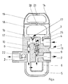
- a connection fitting for filtering liquid fuel is shown. It consists essentially of a fitting housing 1, which has a first connecting piece 2 for connecting a flow line of a fuel tank, a second nozzle 3 for connecting a flow line to a burner and a third nozzle 4 for connecting a return line from the burner. Furthermore, a filter chamber 5 is provided with a filter insert 6 for the fuel.
- the valve body has a first flow channel which connects the first nozzle 2 with the second nozzle 3. This connection is indicated by corresponding arrows in the drawing. The connection takes place via the filter chamber 5 and the filter insert 6. The inflowing fuel is thus filtered and then fed via the second port 3 to the burner.
- the third port 4 communicates with a flow distributor 7, via which the recirculated via the third port 4 fuel in a first Partial volume flow 8 is supplied to the input of the filter cartridge 6, so that this component of the recirculated fuel is filtered again, and is supplied via the in a second partial volume flow 9 of the recirculated fuel to the output of the filter cartridge 6 to the second port 3.
- the flow distributor 7 has in the flow path of the second partial volume flow 9 to a flow resistance explained later or forms such, by means of which the size of the volume flow is determined. Furthermore, the flow distributor 7 in the flow path of the first partial volume flow 8 to a fixed or variably adjustable cross-sectional constriction 10.
- All flow paths of the flow distributor 7 are formed by corresponding flow channels.
- the cross-sectional constriction 10 is formed by a nozzle, an annular gap or a diaphragm.
- a spring-loaded overflow valve 11 As a flow resistance in the flow path of the second partial volume flow 9, a spring-loaded overflow valve 11 is arranged.
- the flow resistance or serving as a flow resistance overflow valve 11 in the flow path of the second partial volume flow 9 opens or releases this flow path, as soon as a sufficiently high pressure through a increased fuel flow in connected to the third port 4 burner return arises.
- a vent pipe 12 in which a manually or by means of a tool operable valve 13 is inserted.
- This valve 13 locks in a first end position, which in FIG. 1 is shown, the output of the vent neck 12.
- the valve 13 opens the way to the vent pipe 12, so that the first partial volume flow, which consists of air or air / fuel mixture, is discharged through the vent pipe 12 to the outside to the atmosphere.
- the valve 13 is also adjustable in an intermediate position, which in FIG. 2 is shown, with this intermediate layer is between the first and second end position. In this intermediate position, the first partial volume flow 8 is shut off, so that the entire volume flow forms the second partial volume flow 9. The opening to the atmosphere is still closed.
- an automatic air vent is provided.
- an automatic ventilation device 14 is installed in the flow path between the third port 4 and the flow distributor 7.
- the third port 4 is open via a flow path 15 with the inlet of the ventilation device 14 connected.
- the venting device 14 is in turn connected via a channel 16 to the flow distributor 7.
- an overflow valve 17 In the channel 16 is an overflow valve 17, which may be spring loaded, for example, arranged.
- floats 18, 19 are arranged, as well as chamber walls with ventilation openings 20, 21.
- a backflow preventer 22 is installed in the first connecting piece 1, for example in the form of a valve body.
Description
Die Erfindung betrifft eine Anschlussarmatur zum Filtern von flüssigem Brennstoff, insbesondere Heizöl, mit einem Armaturengehäuse, das einen ersten Stutzen zum Anschluss einer Vorlaufleitung von einem Brennstofftank, einen zweiten Stutzen für den Anschluss einer Vorlaufleitung zu einem Brennstoff verbrauchenden oder weiterverarbeitenden Brenner, einen dritten Stutzen zum Anschluss einer Rücklaufleitung vom Brenner, und eine Filterkammer mit einem Filtereinsatz für den Brennstoff aufweist, wobei das Armaturengehäuse einen ersten Strömungskanal aufweist, der den ersten Stutzen mit dem zweiten Stutzen über die Filterkammer und den Filtereinsatz verbindet.The invention relates to a connection fitting for filtering liquid fuel, in particular fuel oil, with a fitting housing having a first nozzle for connecting a supply line of a fuel tank, a second nozzle for connecting a flow line to a fuel consuming or further processing burner, a third nozzle for Connecting a return line from the burner, and having a filter chamber with a filter cartridge for the fuel, wherein the valve body has a first flow channel connecting the first port to the second port via the filter chamber and the filter cartridge.
Derartige Anschlussarmaturen sind im Stand der Technik bekannt. Sie sind zwischen einem Brennstofftank und einem Brenner eingebaut. Es wird hierbei durch die entsprechende Ausgestaltung eine Rückführung des unverbrauchten Brennstoffes zum Brenner erreicht. Üblich sind derartige Anschlussarmaturen mit einer zusätzlichen Entlüftungseinrichtung oder mit einer automatischen Entlüfteranordnung.Such connection fittings are known in the art. They are installed between a fuel tank and a burner. It is achieved by the appropriate design, a return of the unconsumed fuel to the burner. Typical are such connection fittings with an additional venting device or with an automatic breather arrangement.
Das beispielsweise vom Brenner nicht verbrauchte Heizöl wird über die Rücklaufleitung und ein federbelastetes Überströmventil der Vorlaufleitung zur Brennerpumpe, und zwar in Strömungsrichtung hinter dem Filtereinsatz wieder zugeführt.The fuel oil not consumed by the burner, for example, is fed back via the return line and a spring-loaded overflow valve of the supply line to the burner pump, namely in the flow direction behind the filter insert.
Hierbei hat der von der Brennerpumpe im Rücklauf erzeugte Überdruck die Funktion, Luft über ein von Hand bedienbares Ventil heraus zu spülen, damit Leitung, Filter und Brennerpumpe entlüftet und nur mit Brennstoff gefüllt werden.Here, the overpressure generated by the burner pump in the return has the function to flush out air via a manually operable valve, so that the line, filter and burner pump are vented and filled only with fuel.
Es sind auch Ausführungsformen bekannt, bei denen für kleine Brennerleistungen der Rücklaufbrennstoff vor den Filtereinsatz zugeführt wird, sodass der Brennstoff mehrfach gefiltert wird.Embodiments are also known in which, for small burner powers, the return fuel is fed in front of the filter insert, so that the fuel is filtered several times.
Aus der
Dem durch das Kapillarrohr gebildeten Strömungskanal ist parallel ein federbelastetes Überströmventil zugeordnet, das größere Rücklaufmengen ebenfalls hinter dem Filtereinsatz dem Brennervorlauf zuführt.The flow channel formed by the capillary tube is associated with a spring-loaded overflow valve in parallel, which also supplies larger return quantities to the burner inlet behind the filter insert.
Eine Mehrfachfilterung findet hier nicht statt. Eine Sicherheitsfunktion, die durch eine derartige Konstruktion erreicht ist, betrifft die Möglichkeit des Schlauchabrisses der Rücklaufleitung. Durch den permanent geöffneten Strömungskanal im Kapillarrohr und Düse wird beim Abriss des Rücklaufschlauches während der Brennstoffversorgung im Saugbetrieb Luft in das System eingesogen und die Anlage schaltet wegen Brennstoffmangel ab. Brenner geht auf Störung. Damit wird ein weiteres Auslaufen von Brennstoff aus der abgerissenen Rücklaufleitung unterbunden.Multiple filtering does not take place here. A safety function achieved by such a construction concerns the possibility of hose breakage of the return line. Due to the permanently open flow channel in the capillary tube and nozzle, air is drawn into the system during the demolition of the return hose during the fuel supply in the suction mode and the system shuts off due to fuel shortage. Brenner goes on error. This prevents further leakage of fuel from the demolished return line.
Im Stand der Technik ist ferner eine entsprechende Armatur bekannt, bei der ein druckloser Rücklauf vorgesehen ist. Im Normalbetrieb ist die Feder eines Überströmventils entspannt. Der gesamte vom Brenner zurückkommende Brennstoff wird direkt wieder der Vorlaufleitung und der Brennerpumpe zugeführt. Eine Baugruppe, bestehend aus Überström- und Entlüftungsventil, spannt erst bei deren Betätigung die Feder des Überströmventils, wobei eine Ventilspindel mit einem Ventilsitz im Filtergehäuse zusammenwirkt. Der so erzeugte Druck in der Rücklaufleitung ermöglicht, dass sowohl Luft/Brennstoff aus der freigegebenen Entlüftungsbohrung der Baugruppe austreten kann, als auch Brennstoff über das Überströmventil weiterhin der Vorlaufleitung zum Brenner zugeführt wird. Eine Mehrfachfilterung findet hierbei nicht statt.In the prior art, a corresponding valve is also known, in which a non-pressurized return is provided. In normal operation, the spring of a relief valve is relaxed. All of the fuel coming back from the burner is returned directly to the supply line and the burner pump. An assembly consisting of overflow and Vent valve, tensioned only when they are actuated, the spring of the overflow valve, wherein a valve stem cooperates with a valve seat in the filter housing. The pressure thus generated in the return line allows both air / fuel can escape from the released vent hole of the assembly, as well as fuel through the spill valve is still supplied to the flow line to the burner. Multiple filtering does not take place here.
Es ist auch eine Ausführung bekannt, bei der eine automatische Entlüftung durch ein Schwimmersystem erfolgt, wobei das Überströmventil dabei ebenfalls durch den von der Brennerpumpe erzeugten Druck, oder über den Füllstand öffnet und der Rücklaufbrennstoff dem Brennervorlauf in Strömungsrichtung hinter dem Filter wieder zugeführt wird. Auch hierbei findet keine Mehrfachfilterung statt.There is also known an embodiment in which an automatic venting takes place by a float system, wherein the overflow also opens by the pressure generated by the burner pump, or on the level and the return fuel is supplied to the burner inlet in the flow direction behind the filter again. Again, no multiple filtering takes place.
Auch bei einer Lösung, die beispielsweise in der
Eine weitere bekannte Lösung ist in der
Bei Brennern mit kleinen Leistungen beziehungsweise Durchsätzen von beispielsweise 20 kW und einem Ölverbrauch von ca. 2 Liter pro Stunde, sammelt sich häufig ein Luftpolster vor einem Filtereinsatz, unabhängig davon, ob es sich um eine Armatur mit automatischer Entlüftung oder mit manueller Entlüftung handelt, insbesondere wenn der Filtereinsatz noch sauber ist. Durch die Mehrfachfilterung wird ein höherer Durchsatz erreicht. Luftblasen sammeln sich dann erfahrungsgemäß wegen der größeren Durchflussmenge nicht vor den Filtereinsätzen.For burners with small outputs or throughputs of, for example, 20 kW and an oil consumption of about 2 liters per hour, often accumulates an air cushion before a filter insert, regardless of whether it is a fitting with automatic ventilation or manual ventilation, in particular when the filter cartridge is still clean. Multiple filtering achieves higher throughput. Air bubbles then collect According to experience, because of the larger flow rate not before the filter cartridges.
Bei großen Brennerleistungen, das heißt, bei größerem Brennstoffdurchsatz, tritt das Luftpolsterproblem nicht auf. Eine Mehrfachfilterung ist dann jedoch nicht mehr umsetzbar, weil der hierdurch verursachte noch höhere Volumenstrom beim Durchströmen des Filters zu große Druckdifferenzen erzeugt, die die Brennerpumpe überwinden müsste.At high burner outputs, that is, with larger fuel flow, the air cushion problem does not occur. However, a multiple filtering is then no longer feasible, because the thereby caused even higher volume flow when flowing through the filter generates too large pressure differences, which would have to overcome the burner pump.
Im Stand der Technik besteht zur Lösung dieses Problems eine manuelle Umschaltmöglichkeit, die aber nur jeweils eine der beiden Betriebszustände ermöglicht.In the prior art, there is a manual switchover to solve this problem, but only one of the two operating states possible.
Bei der oben beschriebenen aus der
Ausgehend von diesem Stand der Technik liegt der Erfindung die Aufgabe zugrunde, eine entsprechende Anschlussarmatur zur Verfügung zu stellen, bei der eine Mehrfachfilterung, insbesondere bei geringem Brennstoffdurchsatz ohne manuelle Umschaltung auf kleine und große Brennerleistung realisiert werden kann.Based on this prior art, the present invention seeks to provide a corresponding connection fitting available in which a multiple filtering, especially at low fuel flow without manual switching to small and large burner power can be realized.
Zur Lösung dieser Aufgabe schlägt die Erfindung vor, dass der dritte Stutzen mit einem Strömungsverteiler kommuniziert, über den der über den dritten Stutzen rückgeführte Brennstoff in einem ersten Teilvolumenstrom dem Eingang des Filtereinsatzes zugeführt ist, und in einem zweiten Teilvolumenstrom dem Ausgang des Filtereinsatzes zum zweiten Stutzen zugeführt ist.To achieve this object, the invention proposes that the third nozzle communicates with a flow distributor via which the fuel returned via the third nozzle is supplied to the inlet of the filter insert in a first partial volume flow, and in a second partial volume flow to the outlet of the filter insert to the second nozzle is supplied.
Hierdurch wird eine Aufteilung des vom Brenner im Normalbetrieb zurückgeführten, nicht verbrauchten Brennstoffes in einen ersten Teilvolumenstrom, der zusammen mit neu angesaugten Brennstoff aus einem Brennstofftank für eine weitere Filterung dem Filtereinsatz zugeführt wird, und in einen zweiten Teilvolumenstrom erreicht, dessen Größe durch einen Strömungswiderstand bestimmt ist und der hinter dem Filtereinsatz zusammen mit dem gefilterten Anteil dem Brennervorlauf zugeführt wird.This results in a division of the recirculated from the burner in normal operation, unused fuel into a first partial flow, which is fed together with newly aspirated fuel from a fuel tank for further filtering the filter insert, and in a second partial flow, the size determined by a flow resistance is and is fed to the burner feed along with the filtered portion behind the filter insert.
Insbesondere ist dabei vorgesehen, dass der Strömungsverteiler im Strömungsweg des zweiten Teilvolumenstromes einen Strömungswiderstand aufweist oder bildet, mittels dessen die Größe des Volumenstroms bestimmt ist.In particular, it is provided that the flow distributor has or forms a flow resistance in the flow path of the second partial volume flow, by means of which the size of the volume flow is determined.
Des Weiteren ist dabei insbesondere vorgesehen, dass der Strömungsverteiler im Strömungsweg des ersten Teilvolumenstroms eine fest eingestellte oder veränderlich einstellbare Querschnittsverengung aufweist.Furthermore, it is provided in particular that the flow distributor in the flow path of the first partial volume flow has a fixed set or variably adjustable cross-sectional constriction.
Der erste Teilvolumenstrom wird durch einen ersten Strömungskanal geführt, der eine feste oder veränderbare Querschnittsverengung aufweist, sodass im Brennervorlauf ein geringerer Druck herrscht als im Rücklauf, wobei der erste Strömungskanal quasi als Bypass zum zweiten Strömungskanal ausgebildet ist. Der zweite Teilstrom wird durch einen zweiten Strömungskanal geführt, der einen Strömungswiderstand aufweist, wodurch erreicht wird, dass dann, wenn ein ausreichend hoher Druck durch einen erhöhten Brennstoffvolumenstrom im Rücklaufkanal beziehungsweise durch eine größere Brennerleistung entsteht, öffnet.The first partial volume flow is guided through a first flow channel, which has a fixed or variable cross-sectional constriction, so that in the burner supply lower pressure prevails than in the return, wherein the first flow channel is formed quasi as a bypass to the second flow channel. The second partial flow is guided through a second flow channel, which has a flow resistance, whereby it is achieved that, when a sufficiently high pressure is created by an increased fuel volume flow in the return channel or by a larger burner output opens.
Insbesondere ist bei diesen Ausgestaltungen vorgesehen, dass die Strömungswege des Strömungsverteilers durch Strömungskanäle gebildet sind.In particular, it is provided in these embodiments that the flow paths of the flow distributor are formed by flow channels.
Besonders bevorzugt ist vorgesehen, dass die Querschnittsverengung durch mindestens eine Düse, einen Ringspalt oder eine Blende gebildet ist.Particularly preferably, it is provided that the cross-sectional constriction is formed by at least one nozzle, an annular gap or a diaphragm.
Ganz besonders bevorzugt ist vorgesehen, dass als Strömungswiderstand im Strömungsweg des zweiten Teilvolumenstroms ein federbelastetes Überströmventil angeordnet ist.Most preferably, it is provided that a spring-loaded overflow valve is arranged as a flow resistance in the flow path of the second partial volume flow.
Durch das federbelastete Überströmventil wird sichergestellt, dass dann, wenn ein ausreichend hoher Druck durch einen erhöhten Brennstoffvolumenstrom im Rücklaufkanal beziehungsweise durch eine größere Brennerleistung entsteht, das Ventil öffnet. Ansonsten ist es durch Federkraft geschlossen.By the spring-loaded overflow valve ensures that, if a sufficiently high pressure by an increased fuel flow in the return channel or due to a larger burner output, the valve opens. Otherwise it is closed by spring force.
Insbesondere wird bei dieser Ausgestaltung erreicht, dass ständig das über den ersten Strömungskanal geführte Strömungsvolumen im normalen Brennerbetrieb mehrfach gefiltert wird. Eine manuelle Umschaltung ist hierbei nicht erforderlich.In particular, in this embodiment, it is achieved that the flow volume guided via the first flow channel is repeatedly filtered several times in normal burner operation. A manual switch is not required here.
Hierbei ist insbesondere vorgesehen, dass der Strömungswiderstand oder ein als Strömungswiderstand dienendes Überströmventil im Strömungsweg des zweiten Teilvolumenstroms öffnet oder den Strömungsweg freigibt, sobald ein ausreichend hoher Druck durch einen erhöhten Brennstoffvolumenstrom im an den dritten Stutzen angeschlossenen Brennerrücklauf entsteht.In this case, it is provided, in particular, that the flow resistance or an overflow valve serving as a flow resistance opens in the flow path of the second partial volume flow or releases the flow path as soon as a sufficiently high pressure is produced by an increased fuel volume flow in the burner return connected to the third connection.
Eine weitere Ausgestaltung besteht darin, dass vom Strömungsweg des ersten Teilvolumenstroms ein Entlüftungsstutzen abzweigt, in den ein manuell oder mittels Werkzeug betätigbares Ventil eingesetzt ist, das in einer ersten Endlage den Ausgang des Entlüftungsstutzens sperrt und in einer zweiten Endlage öffnet und den ersten Teilvolumenstrom, der aus Luft oder Luft/Brennstoffgemisch besteht, durch den Entlüftungsstutzen nach außen z.B. in die Atmosphäre abführt.A further embodiment is that branches off from the flow path of the first partial volume flow a vent pipe into which a manually or by means of actuatable valve is used, which blocks the output of the vent in a first end position and opens in a second end position and the first partial flow, the consists of air or air / fuel mixture through the vent to the outside eg dissipates into the atmosphere.
Hierbei ist eine manuelle oder mittels Werkzeug betätigbare Entlüftungsmöglichkeit zur Verfügung gestellt, wobei in der ersten Endlage der normale Betrieb ermöglicht ist und in der zweiten Endlage der erste Teilvolumenstrom, der aus Luft oder einem Luft/Brennstoffgemisch besteht, durch die Entlüftereinheit in die Umgebung abgeführt wird.In this case, a manual or by means of tool actuable ventilation option is available provided, wherein in the first end position of the normal operation is made possible and in the second end position of the first partial volume flow, which consists of air or an air / fuel mixture is discharged through the vent unit into the environment.
Bevorzugt ist dabei vorgesehen, dass das Ventil in eine Zwischenlage zwischen erster und zweiter Endlage einstellbar ist, wobei in der Zwischenlage der erste Teilvolumenstrom abgesperrt ist und der gesamte Volumenstrom den zweiten teilvolumenstrom bildet.Preferably, it is provided that the valve is adjustable in an intermediate position between the first and second end position, wherein in the intermediate position of the first partial volume flow is shut off and the entire volume flow forms the second part volume flow.
In der Zwischenlage, in der der erste Strömungskanal geschlossen ist, wird der gesamte Rücklaufbrennstoff durch den zweiten Strömungskanal geführt und nur der neu aus einem Heizöltank angesaugte Brennstoff gefiltert.In the intermediate layer, in which the first flow channel is closed, the entire return fuel is passed through the second flow channel and filtered only the newly sucked from a fuel oil tank fuel.
Eine alternative bevorzugte Ausgestaltung wird darin gesehen, dass im Strömungsweg zwischen dem dritten Stutzen und dem Strömungsverteiler eine automatische Entlüftungsvorrichtung installiert ist.An alternative preferred embodiment is seen in that in the flow path between the third nozzle and the flow distributor, an automatic ventilation device is installed.
Hierbei ist bevorzugt vorgesehen, dass der dritte Stutzen über einen Strömungsweg offen mit dem Eingang der Entlüftungsvorrichtung kommuniziert und die Entlüftungsvorrichtung über einen Kanal mit dem Strömungsverteiler verbunden ist, in welchen Kanal ein federbelastetes Überströmventil eingesetzt ist. Es wird hierbei eine automatische Entlüftung erreicht, wie dies im Stand der Technik an sich bekannt ist.In this case, it is preferably provided that the third connection communicates openly with the inlet of the ventilation device via a flow path and the ventilation device is connected via a channel to the flow distributor, in which channel a spring-loaded overflow valve is inserted. In this case, an automatic venting is achieved, as is known per se in the prior art.
Insbesondere bei der Ausgestaltung, bei der eine manuelle Entlüftung vorgesehen ist, ist auch weiterhin im Falle einer abgerissenen Rücklaufleitung eine gewollte Brennerstörung erreicht, bei der Luft über den ersten Strömungskanal angesaugt wird, sodass der Brenner infolge Brennstoffmangel abschaltet. Dies ist eine Sicherheitsfunktion bei Schlauchabriss.In particular, in the embodiment in which a manual venting is provided, a deliberate burner failure is still achieved in the case of a demolished return line, is sucked in the air over the first flow channel, so that the burner shuts off due to fuel shortage. This is a safety function in case of hose breakage.
Zusammengefasst sind die Besonderheiten der Erfindung folgende:
- Es erfolgt eine Aufteilung des vom Brenner im Normalbetrieb zurückgeführten, nicht verbrauchten Brennstoffes in einen ersten Teilvolumenstrom, der zusammen mit neu angesaugtem Brennstoff aus einem Brennstofftank für eine weitere Filterung dem Filtereinsatz zugeführt wird und in einen zweiten Teilvolumenstrom, dessen Größe durch einen Strömungswiderstand bestimmt ist und der hinter dem Filter zusammen mit dem gefilterten Anteil dem Brennervorlauf zugeführt wird.
- There is a division of the recirculated from the burner in normal operation, unused fuel in a first partial volume flow, which is supplied together with newly aspirated fuel from a fuel tank for further filtering the filter insert and in a second partial volume flow whose size is determined by a flow resistance and which is fed behind the filter together with the filtered portion of the burner feed.
Der erste Teilvolumenstrom wird durch einen ersten Strömungskanal geführt, der eine feste oder veränderbare Querschnittsverengung, beispielsweise eine Düse oder einen Ringspalt aufweist, sodass im Brennervorlauf ein geringerer Druck herrscht als im Rücklauf, wobei der erste Strömungskanal als Bypass zum zweiten Strömungskanal ausgebildet ist.The first partial volume flow is guided through a first flow channel, which has a fixed or variable cross-sectional constriction, for example a nozzle or an annular gap, so that a lower pressure prevails in the burner inlet than in Return, wherein the first flow channel is formed as a bypass to the second flow channel.
Der zweite Teilvolumenstrom wird durch einen zweiten Strömungskanal geführt, der als Strömungswiderstand zum Beispiel ein federbelastetes Überströmventil aufweist, welches, sobald ein ausreichend hoher Druck durch einen erhöhten Brennstoffvolumenstrom im Rücklaufkanal entsteht, öffnet.The second partial volume flow is passed through a second flow channel, which has as a flow resistance, for example, a spring-loaded overflow valve, which, as soon as a sufficiently high pressure arises through an increased fuel volume flow in the return channel opens.
Es ist eine manuell zu bedienende Entlüftereinheit vorgesehen, die im Armaturengehäuse in der einen Endlage den Normalbetrieb ermöglicht und in der anderen Endlage den ersten Teilvolumenstrom, der aus Luft oder einem Luft/Brennstoffgemisch besteht, durch die Entlüftereinheit in die Umgebung abführt.There is provided a manually operated vent unit, the normal operation in the valve housing in one end position and in the other end position, the first partial volume flow, which consists of air or an air / fuel mixture, dissipates through the vent unit into the environment.
In einer Mittelstellung des Entlüfterventils der manuell zu bedienenden Entlüftereinheit ist der erste Strömungskanal geschlossen und der gesamte Rücklaufbrennstoff wird durch den zweiten Strömungskanal geführt. Dabei wird nur der aus dem Brennstofftank angesaugte Brennstoff gefiltert.In a middle position of the breather valve of the manually operated vent unit, the first flow channel is closed and the entire return fuel is passed through the second flow channel. Only the fuel sucked from the fuel tank is filtered.
Ausführungsbeispiele der Erfindung sind in der Zeichnung dargestellt und im Folgenden näher beschrieben:
- Es zeigt:
- Figur 1-3
- eine erste Ausführungsform einer erfindungsgemäßen Anschlussarmatur im Mittelschnitt gesehen;
Figur 4- eine zweite Ausführungsform in gleicher Ansicht.
- It shows:
- Figure 1-3
- a first embodiment of a connection fitting according to the invention seen in the central section;
- FIG. 4
- a second embodiment in the same view.
In den Zeichnungen sind die Brennstoffwege durch Pfeile symbolisiert.In the drawings, the fuel paths are symbolized by arrows.
In den Ausführungsbeispielen ist eine Anschlussarmatur zum Filtern von flüssigem Brennstoff gezeigt. Sie besteht im Wesentlichen aus einem Armaturengehäuse 1, welches einen ersten Anschlussstutzen 2 zum Anschluss einer Vorlaufleitung von einem Brennstofftank, einen zweiten Stutzen 3 für den Anschluss einer Vorlaufleitung zu einem Brenner und einen dritten Stutzen 4 zum Anschluss einer Rücklaufleitung vom Brenner aufweist. Des Weiteren ist eine Filterkammer 5 mit einem Filtereinsatz 6 für den Brennstoff vorgesehen.In the exemplary embodiments, a connection fitting for filtering liquid fuel is shown. It consists essentially of a
Das Armaturengehäuse weist einen ersten Strömungskanal auf, der den ersten Stutzen 2 mit dem zweiten Stutzen 3 verbindet. Diese Verbindung ist durch entsprechende Pfeile in der Zeichnung angegeben. Die Verbindung erfolgt über die Filterkammer 5 und den Filtereinsatz 6. Der zuströmende Brennstoff wird somit gefiltert und dann über den zweiten Stutzen 3 dem Brenner zugeführt.The valve body has a first flow channel which connects the
Der dritte Stutzen 4 kommuniziert mit einem Strömungsverteiler 7, über den der über den dritten Stutzen 4 rückgeführte Brennstoff in einen ersten Teilvolumenstrom 8 dem Eingang des Filtereinsatzes 6 zugeführt wird, sodass dieser Bestandteil des rückgeführten Brennstoffes erneut gefiltert wird, und über den in einem zweiten Teilvolumenstrom 9 der rückgeführte Brennstoff dem Ausgang des Filtereinsatzes 6 zum zweiten Stutzen 3 zugeführt wird.The
Der Strömungsverteiler 7 weist im Strömungsweg des zweiten Teilvolumenstromes 9 einen später noch erläuterten Strömungswiderstand auf oder bildet einen solchen, mittels dessen die Größe des Volumenstroms bestimmt ist. Des Weiteren weist der Strömungsverteiler 7 im Strömungsweg des ersten Teilvolumenstroms 8 eine fest eingestellte oder veränderlich einstellbare Querschnittsverengung 10 auf.The
Alle Strömungswege des Strömungsverteilers 7 sind durch entsprechende Strömungskanäle gebildet. Die Querschnittsverengung 10 ist durch eine Düse, einen Ringspalt oder eine Blende gebildet.All flow paths of the
Als Strömungswiderstand im Strömungsweg des zweiten Teilvolumenstromes 9 ist ein federbelastetes Überströmventil 11 angeordnet. Der Strömungswiderstand beziehungsweise das als Strömungswiderstand dienende Überströmventil 11 im Strömungsweg des zweiten Teilvolumenstromes 9 öffnet beziehungsweise gibt diesen Strömungsweg frei, sobald ein ausreichend hoher Druck durch einen erhöhten Brennstoffvolumenstrom im an den dritten Stutzen 4 angeschlossenen Brennerrücklauf entsteht.As a flow resistance in the flow path of the second
Bei der Ausführungsform nach
Das Ventil 13 ist auch in eine Zwischenlage einstellbar, die in
Bei der Ausführungsform nach
In der Betriebsweise gemäß
In der Betriebsweise gemäß
In der Entlüftungsstellung gemäß
Bei der Ausführungsform nach
Die Erfindung ist nicht auf die Ausführungsbeispiele beschränkt, sondern im Rahmen der Ansprüche vielfach variabel.The invention is not limited to the embodiments, but often variable within the scope of the claims.
- 1.1.
- Armaturengehäusefitting housing
- 2.Second
- erster Stutzenfirst nozzle
- 3.Third
- zweiter Stutzensecond nozzle
- 4.4th
- dritter Stutzenthird neck
- 5.5th
- Filterkammerfilter chamber
- 6.6th
- Filtereinsatzfilter cartridge
- 7.7th
- Strömungsverteilerflow distributor
- 8.8th.
- erster Volumenstromfirst volume flow
- 9.9th
- zweiter Volumenstromsecond volume flow
- 10.10th
- QuerschnittsverengungCross-sectional narrowing
- 11.11th
- Überströmventiloverflow
- 12.12th
- Entlüftungsstutzenvent connection
- 13.13th
- VentilValve
- 14.14th
- automatische Entlüftungsvorrichtungautomatic ventilation device
- 15.15th
- Strömungswegflow
- 16.16th
- Kanalchannel
- 17.17th
- Überströmventiloverflow
- 18.18th
- Schwimmerswimmer
- 19.19th
- Schwimmerswimmer
- 20.20th
- Entlüftungsöffnungvent
- 21.21st
- Entlüftungsöffnungvent
- 22.22nd
- RückflussverhindererBackflow preventer
Claims (11)
- A connection fitting for filtering liquid fuel, in particular fuel oil, comprising a fitting housing (1) having a first nipple (2) for connecting a feed line from a fuel tank, a second nipple (3) for connecting a feed line to a fuel consuming or processing burner, a third nipple (4) for connecting a return line from the burner, and a filter chamber (5) with a filter cartridge (6) for the fuel, the fitting housing (1) including a first flow channel that connects the first nipple (2) to the second nipple (3) through the filter chamber (5) and the filter cartridge (6), characterized by that the third nipple (4) communicates with a flow distributor (7), by means of which the fuel returned through the third nipple (4) is fed, in a first partial volume flow (8), to the entrance of the filter cartridge (6), and is fed, in a second partial volume flow (9), to the exit of the filter cartridge (6) to the second nipple (3).
- The connection fitting according to claim 1, characterized by that the flow distributor (7) includes or forms, in the flow path of the second partial volume flow (9), a flow resistance, by means of which the value of the volume flow is determined.
- The connection fitting according to one of claims 1 or 2, characterized by that the flow distributor (7) in the flow path of the first partial volume flow (8) includes a fixed or variably adjustable constriction of the cross section (10).
- The connection fitting according to one of claims 1 to 3, characterized by that the flow paths of the flow distributor (7) are formed by flow channels.
- The connection fitting according to one of claims 3 or 4, characterized by that the constriction of the cross section (10) is formed by at least one nozzle, annular gap, or orifice plate.
- The connection fitting according to one of claims 2 to 5, characterized by that as a flow resistance, a spring-loaded pressure-relief valve (11) is disposed in the flow path of the second partial volume flow (9).
- The connection fitting according to one of claims 2 to 6, characterized by that the flow resistance or a pressure-relief valve (11) serving as the flow resistance in the flow path of the second partial volume flow (9) opens or releases the flow path, as soon as a sufficiently high pressure exists by an increased fuel volume flow in the burner return line connected to the third nipple (4).
- The connection fitting according to one of claims 1 to 7, characterized by that from the flow path of the first partial volume flow (8) branches off a ventilation nipple (12), in which a valve (13) to be operated manually or by means of a tool is included, which in a first end position blocks the exit of the ventilation nipple (12) and in a second end position opens and discharges the first partial volume flow (8) composed of air or an air/fuel mixture, outwardly through the ventilation nipple (12), e.g., into the atmosphere.
- The connection fitting according to claim 8, characterized by that the valve (13) is adjustable to an intermediate position between the first and second end positions, in the intermediate position the first partial volume flow (8) being blocked and the total volume flow forming the second partial volume flow (9).
- The connection fitting according to one of claims 1 to 7, characterized by that in the flow path between the third nipple (4) and the flow distributor (7), an automatic ventilation device (14) is installed.
- The connection fitting according to claim 10, characterized by that via a flow path (15), the third nipple (4) openly communicates with the entrance of the ventilation device (14), and the ventilation device (14) is connected through a channel (16) with the flow distributor (7), in which channel (16) a pressure-relief valve (17) being provided.
Applications Claiming Priority (1)
| Application Number | Priority Date | Filing Date | Title |
|---|---|---|---|
| DE102014107760.1A DE102014107760A1 (en) | 2014-06-03 | 2014-06-03 | Connection fitting for filtering liquid media |
Publications (2)
| Publication Number | Publication Date |
|---|---|
| EP2952810A1 EP2952810A1 (en) | 2015-12-09 |
| EP2952810B1 true EP2952810B1 (en) | 2016-11-23 |
Family
ID=53783029
Family Applications (1)
| Application Number | Title | Priority Date | Filing Date |
|---|---|---|---|
| EP15167239.1A Active EP2952810B1 (en) | 2014-06-03 | 2015-05-12 | Valve assembly for filtering liquid fuel |
Country Status (2)
| Country | Link |
|---|---|
| EP (1) | EP2952810B1 (en) |
| DE (1) | DE102014107760A1 (en) |
Families Citing this family (3)
| Publication number | Priority date | Publication date | Assignee | Title |
|---|---|---|---|---|
| CN108488014A (en) * | 2018-03-09 | 2018-09-04 | 安徽江淮汽车集团股份有限公司 | A kind of fuel oil temperature regulating system |
| DE102020211027B3 (en) | 2020-09-02 | 2022-01-20 | AFRISO-EURO-INDEX Gesellschaft mit beschränkter Haftung | Filter device for filtering heating oil with overflow-protected filter cup |
| DE102020211029A1 (en) | 2020-09-02 | 2022-03-03 | AFRISO-EURO-INDEX Gesellschaft mit beschränkter Haftung | Filter device for filtering heating oil with an emptying device |
Family Cites Families (6)
| Publication number | Priority date | Publication date | Assignee | Title |
|---|---|---|---|---|
| DE1917459U (en) * | 1965-04-08 | 1965-06-10 | Kurt Hastenteufel | PIPE ARRANGEMENT FOR HEATING SYSTEMS WITH OIL FIRING. |
| DE4238044C1 (en) | 1992-11-11 | 1993-12-16 | Josef Dipl Ing Gottfried | Single-stage self-venting heating-oil filter - has air-extraction pipe from collector-vessel top connected to fuel pipe leading to burner pump |
| US5887572A (en) * | 1997-05-05 | 1999-03-30 | Ford Global Technologies, Inc. | Pressure and temperature control for fuel delivery systems |
| DE102005006878B4 (en) | 2005-02-14 | 2012-02-09 | F.W. Oventrop Gmbh & Co. Kg | Connection fitting with heating oil filter |
| FR2960597B1 (en) * | 2010-05-25 | 2012-06-22 | Snecma | DEVICE FOR DERIVING CONDUIT IN A FLUID CIRCUIT |
| EP2446951B1 (en) | 2010-10-26 | 2012-10-10 | AFRISO-EURO-INDEX GmbH | Device for filtering and removing air from heating oil with return flow valve |
-
2014
- 2014-06-03 DE DE102014107760.1A patent/DE102014107760A1/en not_active Withdrawn
-
2015
- 2015-05-12 EP EP15167239.1A patent/EP2952810B1/en active Active
Non-Patent Citations (1)
| Title |
|---|
| None * |
Also Published As
| Publication number | Publication date |
|---|---|
| EP2952810A1 (en) | 2015-12-09 |
| DE102014107760A1 (en) | 2015-12-03 |
Similar Documents
| Publication | Publication Date | Title |
|---|---|---|
| DE112010000058B4 (en) | Valve system for vehicle high-pressure tank | |
| DD248520A5 (en) | DEVICE FOR RINOING A LINE SYSTEM | |
| DE102008032560A1 (en) | System and method for priming in a fluid system | |
| EP2952810B1 (en) | Valve assembly for filtering liquid fuel | |
| WO2006136328A1 (en) | Fuel supply device | |
| DE2533164C3 (en) | Hydraulic control device for a hydraulic system | |
| DE10250532B3 (en) | Propellant powered ejector assembly | |
| EP2196635A2 (en) | Device for avoiding high oil tank pressures under negative g conditions | |
| EP3145618B1 (en) | Filter device | |
| EP3352877B1 (en) | Filter device with pump | |
| DE102015222049A1 (en) | Low-pressure circuit | |
| EP2446951B1 (en) | Device for filtering and removing air from heating oil with return flow valve | |
| DE112014006491T5 (en) | filter regulator | |
| WO2021254718A1 (en) | Venting device | |
| DE102020119668B4 (en) | Internal combustion engine with at least two oil separators | |
| DE4335858B4 (en) | Fuel conveyor for an internal combustion engine | |
| DE19850810B4 (en) | Connection fitting with a heating oil filter for heating systems | |
| DE3802102C2 (en) | ||
| DE102010029830B4 (en) | Suction oil filter with a bypass and control of the bypass | |
| DE102007020352A1 (en) | Filter clogging detection system | |
| DE102007010472B4 (en) | Sanitary low pressure fitting | |
| DE1922360A1 (en) | Oil pump | |
| DE19901964B4 (en) | Valve group especially for a water purifier machine | |
| DE102017008220B4 (en) | Device for deactivating a multi-way valve | |
| DE3205411A1 (en) | Bleed device for a hydraulic unit |
Legal Events
| Date | Code | Title | Description |
|---|---|---|---|
| PUAI | Public reference made under article 153(3) epc to a published international application that has entered the european phase |
Free format text: ORIGINAL CODE: 0009012 |
|
| AK | Designated contracting states |
Kind code of ref document: A1 Designated state(s): AL AT BE BG CH CY CZ DE DK EE ES FI FR GB GR HR HU IE IS IT LI LT LU LV MC MK MT NL NO PL PT RO RS SE SI SK SM TR |
|
| AX | Request for extension of the european patent |
Extension state: BA ME |
|
| 17P | Request for examination filed |
Effective date: 20160324 |
|
| RBV | Designated contracting states (corrected) |
Designated state(s): AL AT BE BG CH CY CZ DE DK EE ES FI FR GB GR HR HU IE IS IT LI LT LU LV MC MK MT NL NO PL PT RO RS SE SI SK SM TR |
|
| GRAP | Despatch of communication of intention to grant a patent |
Free format text: ORIGINAL CODE: EPIDOSNIGR1 |
|
| RIC1 | Information provided on ipc code assigned before grant |
Ipc: F23K 5/18 20060101AFI20160614BHEP |
|
| INTG | Intention to grant announced |
Effective date: 20160706 |
|
| GRAS | Grant fee paid |
Free format text: ORIGINAL CODE: EPIDOSNIGR3 |
|
| GRAA | (expected) grant |
Free format text: ORIGINAL CODE: 0009210 |
|
| AK | Designated contracting states |
Kind code of ref document: B1 Designated state(s): AL AT BE BG CH CY CZ DE DK EE ES FI FR GB GR HR HU IE IS IT LI LT LU LV MC MK MT NL NO PL PT RO RS SE SI SK SM TR |
|
| REG | Reference to a national code |
Ref country code: GB Ref legal event code: FG4D Free format text: NOT ENGLISH |
|
| REG | Reference to a national code |
Ref country code: CH Ref legal event code: NV Representative=s name: TROESCH SCHEIDEGGER WERNER AG, CH Ref country code: CH Ref legal event code: EP |
|
| REG | Reference to a national code |
Ref country code: IE Ref legal event code: FG4D Free format text: LANGUAGE OF EP DOCUMENT: GERMAN |
|
| REG | Reference to a national code |
Ref country code: AT Ref legal event code: REF Ref document number: 848261 Country of ref document: AT Kind code of ref document: T Effective date: 20161215 |
|
| REG | Reference to a national code |
Ref country code: DE Ref legal event code: R096 Ref document number: 502015000322 Country of ref document: DE |
|
| PG25 | Lapsed in a contracting state [announced via postgrant information from national office to epo] |
Ref country code: LV Free format text: LAPSE BECAUSE OF FAILURE TO SUBMIT A TRANSLATION OF THE DESCRIPTION OR TO PAY THE FEE WITHIN THE PRESCRIBED TIME-LIMIT Effective date: 20161123 |
|
| REG | Reference to a national code |
Ref country code: LT Ref legal event code: MG4D |
|
| REG | Reference to a national code |
Ref country code: NL Ref legal event code: MP Effective date: 20161123 |
|
| PG25 | Lapsed in a contracting state [announced via postgrant information from national office to epo] |
Ref country code: SE Free format text: LAPSE BECAUSE OF FAILURE TO SUBMIT A TRANSLATION OF THE DESCRIPTION OR TO PAY THE FEE WITHIN THE PRESCRIBED TIME-LIMIT Effective date: 20161123 Ref country code: NL Free format text: LAPSE BECAUSE OF FAILURE TO SUBMIT A TRANSLATION OF THE DESCRIPTION OR TO PAY THE FEE WITHIN THE PRESCRIBED TIME-LIMIT Effective date: 20161123 Ref country code: LT Free format text: LAPSE BECAUSE OF FAILURE TO SUBMIT A TRANSLATION OF THE DESCRIPTION OR TO PAY THE FEE WITHIN THE PRESCRIBED TIME-LIMIT Effective date: 20161123 Ref country code: GR Free format text: LAPSE BECAUSE OF FAILURE TO SUBMIT A TRANSLATION OF THE DESCRIPTION OR TO PAY THE FEE WITHIN THE PRESCRIBED TIME-LIMIT Effective date: 20170224 Ref country code: NO Free format text: LAPSE BECAUSE OF FAILURE TO SUBMIT A TRANSLATION OF THE DESCRIPTION OR TO PAY THE FEE WITHIN THE PRESCRIBED TIME-LIMIT Effective date: 20170223 |
|
| REG | Reference to a national code |
Ref country code: FR Ref legal event code: PLFP Year of fee payment: 3 |
|
| PG25 | Lapsed in a contracting state [announced via postgrant information from national office to epo] |
Ref country code: HR Free format text: LAPSE BECAUSE OF FAILURE TO SUBMIT A TRANSLATION OF THE DESCRIPTION OR TO PAY THE FEE WITHIN THE PRESCRIBED TIME-LIMIT Effective date: 20161123 Ref country code: PL Free format text: LAPSE BECAUSE OF FAILURE TO SUBMIT A TRANSLATION OF THE DESCRIPTION OR TO PAY THE FEE WITHIN THE PRESCRIBED TIME-LIMIT Effective date: 20161123 Ref country code: PT Free format text: LAPSE BECAUSE OF FAILURE TO SUBMIT A TRANSLATION OF THE DESCRIPTION OR TO PAY THE FEE WITHIN THE PRESCRIBED TIME-LIMIT Effective date: 20170323 Ref country code: ES Free format text: LAPSE BECAUSE OF FAILURE TO SUBMIT A TRANSLATION OF THE DESCRIPTION OR TO PAY THE FEE WITHIN THE PRESCRIBED TIME-LIMIT Effective date: 20161123 Ref country code: RS Free format text: LAPSE BECAUSE OF FAILURE TO SUBMIT A TRANSLATION OF THE DESCRIPTION OR TO PAY THE FEE WITHIN THE PRESCRIBED TIME-LIMIT Effective date: 20161123 Ref country code: FI Free format text: LAPSE BECAUSE OF FAILURE TO SUBMIT A TRANSLATION OF THE DESCRIPTION OR TO PAY THE FEE WITHIN THE PRESCRIBED TIME-LIMIT Effective date: 20161123 |
|
| PG25 | Lapsed in a contracting state [announced via postgrant information from national office to epo] |
Ref country code: RO Free format text: LAPSE BECAUSE OF FAILURE TO SUBMIT A TRANSLATION OF THE DESCRIPTION OR TO PAY THE FEE WITHIN THE PRESCRIBED TIME-LIMIT Effective date: 20161123 Ref country code: SK Free format text: LAPSE BECAUSE OF FAILURE TO SUBMIT A TRANSLATION OF THE DESCRIPTION OR TO PAY THE FEE WITHIN THE PRESCRIBED TIME-LIMIT Effective date: 20161123 Ref country code: CZ Free format text: LAPSE BECAUSE OF FAILURE TO SUBMIT A TRANSLATION OF THE DESCRIPTION OR TO PAY THE FEE WITHIN THE PRESCRIBED TIME-LIMIT Effective date: 20161123 Ref country code: DK Free format text: LAPSE BECAUSE OF FAILURE TO SUBMIT A TRANSLATION OF THE DESCRIPTION OR TO PAY THE FEE WITHIN THE PRESCRIBED TIME-LIMIT Effective date: 20161123 Ref country code: EE Free format text: LAPSE BECAUSE OF FAILURE TO SUBMIT A TRANSLATION OF THE DESCRIPTION OR TO PAY THE FEE WITHIN THE PRESCRIBED TIME-LIMIT Effective date: 20161123 |
|
| REG | Reference to a national code |
Ref country code: DE Ref legal event code: R097 Ref document number: 502015000322 Country of ref document: DE |
|
| PG25 | Lapsed in a contracting state [announced via postgrant information from national office to epo] |
Ref country code: BG Free format text: LAPSE BECAUSE OF FAILURE TO SUBMIT A TRANSLATION OF THE DESCRIPTION OR TO PAY THE FEE WITHIN THE PRESCRIBED TIME-LIMIT Effective date: 20170223 Ref country code: SM Free format text: LAPSE BECAUSE OF FAILURE TO SUBMIT A TRANSLATION OF THE DESCRIPTION OR TO PAY THE FEE WITHIN THE PRESCRIBED TIME-LIMIT Effective date: 20161123 Ref country code: LU Free format text: LAPSE BECAUSE OF NON-PAYMENT OF DUE FEES Effective date: 20170531 Ref country code: IT Free format text: LAPSE BECAUSE OF FAILURE TO SUBMIT A TRANSLATION OF THE DESCRIPTION OR TO PAY THE FEE WITHIN THE PRESCRIBED TIME-LIMIT Effective date: 20161123 |
|
| PLBE | No opposition filed within time limit |
Free format text: ORIGINAL CODE: 0009261 |
|
| STAA | Information on the status of an ep patent application or granted ep patent |
Free format text: STATUS: NO OPPOSITION FILED WITHIN TIME LIMIT |
|
| 26N | No opposition filed |
Effective date: 20170824 |
|
| PG25 | Lapsed in a contracting state [announced via postgrant information from national office to epo] |
Ref country code: SI Free format text: LAPSE BECAUSE OF FAILURE TO SUBMIT A TRANSLATION OF THE DESCRIPTION OR TO PAY THE FEE WITHIN THE PRESCRIBED TIME-LIMIT Effective date: 20161123 |
|
| PG25 | Lapsed in a contracting state [announced via postgrant information from national office to epo] |
Ref country code: MC Free format text: LAPSE BECAUSE OF FAILURE TO SUBMIT A TRANSLATION OF THE DESCRIPTION OR TO PAY THE FEE WITHIN THE PRESCRIBED TIME-LIMIT Effective date: 20161123 |
|
| REG | Reference to a national code |
Ref country code: IE Ref legal event code: MM4A |
|
| PG25 | Lapsed in a contracting state [announced via postgrant information from national office to epo] |
Ref country code: LU Free format text: LAPSE BECAUSE OF NON-PAYMENT OF DUE FEES Effective date: 20170512 |
|
| REG | Reference to a national code |
Ref country code: BE Ref legal event code: MM Effective date: 20170531 |
|
| PG25 | Lapsed in a contracting state [announced via postgrant information from national office to epo] |
Ref country code: IE Free format text: LAPSE BECAUSE OF NON-PAYMENT OF DUE FEES Effective date: 20170512 |
|
| REG | Reference to a national code |
Ref country code: FR Ref legal event code: PLFP Year of fee payment: 4 |
|
| PG25 | Lapsed in a contracting state [announced via postgrant information from national office to epo] |
Ref country code: BE Free format text: LAPSE BECAUSE OF NON-PAYMENT OF DUE FEES Effective date: 20170531 |
|
| PG25 | Lapsed in a contracting state [announced via postgrant information from national office to epo] |
Ref country code: MT Free format text: LAPSE BECAUSE OF FAILURE TO SUBMIT A TRANSLATION OF THE DESCRIPTION OR TO PAY THE FEE WITHIN THE PRESCRIBED TIME-LIMIT Effective date: 20161123 |
|
| PG25 | Lapsed in a contracting state [announced via postgrant information from national office to epo] |
Ref country code: HU Free format text: LAPSE BECAUSE OF FAILURE TO SUBMIT A TRANSLATION OF THE DESCRIPTION OR TO PAY THE FEE WITHIN THE PRESCRIBED TIME-LIMIT; INVALID AB INITIO Effective date: 20150512 |
|
| PG25 | Lapsed in a contracting state [announced via postgrant information from national office to epo] |
Ref country code: CY Free format text: LAPSE BECAUSE OF FAILURE TO SUBMIT A TRANSLATION OF THE DESCRIPTION OR TO PAY THE FEE WITHIN THE PRESCRIBED TIME-LIMIT Effective date: 20161123 |
|
| PG25 | Lapsed in a contracting state [announced via postgrant information from national office to epo] |
Ref country code: MK Free format text: LAPSE BECAUSE OF FAILURE TO SUBMIT A TRANSLATION OF THE DESCRIPTION OR TO PAY THE FEE WITHIN THE PRESCRIBED TIME-LIMIT Effective date: 20161123 |
|
| PG25 | Lapsed in a contracting state [announced via postgrant information from national office to epo] |
Ref country code: TR Free format text: LAPSE BECAUSE OF FAILURE TO SUBMIT A TRANSLATION OF THE DESCRIPTION OR TO PAY THE FEE WITHIN THE PRESCRIBED TIME-LIMIT Effective date: 20161123 |
|
| PG25 | Lapsed in a contracting state [announced via postgrant information from national office to epo] |
Ref country code: AL Free format text: LAPSE BECAUSE OF FAILURE TO SUBMIT A TRANSLATION OF THE DESCRIPTION OR TO PAY THE FEE WITHIN THE PRESCRIBED TIME-LIMIT Effective date: 20161123 Ref country code: IS Free format text: LAPSE BECAUSE OF FAILURE TO SUBMIT A TRANSLATION OF THE DESCRIPTION OR TO PAY THE FEE WITHIN THE PRESCRIBED TIME-LIMIT Effective date: 20170323 |
|
| P01 | Opt-out of the competence of the unified patent court (upc) registered |
Effective date: 20230510 |
|
| PGFP | Annual fee paid to national office [announced via postgrant information from national office to epo] |
Ref country code: FR Payment date: 20230524 Year of fee payment: 9 Ref country code: CH Payment date: 20230602 Year of fee payment: 9 |
|
| PGFP | Annual fee paid to national office [announced via postgrant information from national office to epo] |
Ref country code: AT Payment date: 20230526 Year of fee payment: 9 |
|
| PGFP | Annual fee paid to national office [announced via postgrant information from national office to epo] |
Ref country code: GB Payment date: 20230530 Year of fee payment: 9 |
|
| PGFP | Annual fee paid to national office [announced via postgrant information from national office to epo] |
Ref country code: DE Payment date: 20230731 Year of fee payment: 9 |