EP0004858A2 - Bending apparatus for tubes - Google Patents
Bending apparatus for tubes Download PDFInfo
- Publication number
- EP0004858A2 EP0004858A2 EP79100531A EP79100531A EP0004858A2 EP 0004858 A2 EP0004858 A2 EP 0004858A2 EP 79100531 A EP79100531 A EP 79100531A EP 79100531 A EP79100531 A EP 79100531A EP 0004858 A2 EP0004858 A2 EP 0004858A2
- Authority
- EP
- European Patent Office
- Prior art keywords
- handle
- pump group
- motor pump
- fluid
- valve
- Prior art date
- Legal status (The legal status is an assumption and is not a legal conclusion. Google has not performed a legal analysis and makes no representation as to the accuracy of the status listed.)
- Granted
Links
Images

Classifications
-
- B—PERFORMING OPERATIONS; TRANSPORTING
- B21—MECHANICAL METAL-WORKING WITHOUT ESSENTIALLY REMOVING MATERIAL; PUNCHING METAL
- B21D—WORKING OR PROCESSING OF SHEET METAL OR METAL TUBES, RODS OR PROFILES WITHOUT ESSENTIALLY REMOVING MATERIAL; PUNCHING METAL
- B21D7/00—Bending rods, profiles, or tubes
- B21D7/06—Bending rods, profiles, or tubes in press brakes or between rams and anvils or abutments; Pliers with forming dies
Definitions
- the present invention relates to a device for bending and / or bending pipes and rods, in particular pipes used for heating systems, for laying in their seats, and to a remote-controlled motor pump group intended for this device.
- Machines and devices for bending tubes and bars are known; however, they generally have a large, i.e. excessive weight to be used for bending work at the place of use.
- the known motor pump groups are not suitable for easy transportation by hand. They are also not suitable for small quantities of oil at an operating pressure of 130 bar. Furthermore, they cannot be switched on and / or off by a control means arranged on the bending device.
- the invention has set itself the task of realizing a device for bending and / or bending steel or copper pipes of any length, in particular for heating systems when laying the pipes in the predetermined seats in walls or floors.
- Another object is to implement a device which is actuated by a fluid in the form of DI and is equipped with organs which enable sensitive regulation of the stamp feed, and which is also tangible and can be operated with one hand, so that the other hand remains free to guide the pipe to be bent.
- the device has supports for the pipe to be bent, which are arranged on a support part from which a handle extends, which includes a shaft which can be axially displaced for bending and / or bending with a controllable angular width, the handle in addition, a fluid flows continuously in a closed circuit, the flow rate of which can be regulated by a throttle element, the resulting increase in pressure of the fluid in front of the throttle element serving to exert a feed pressure on the shaft.
- the object of the invention is to provide a motor pump group which is suitable for the bending device and which can be switched on and / or off by remote control with the same hand that holds the device.
- the motor pump group is characterized in that the pump is enclosed in a collection container for the fluid for actuating the device, in order to form a closed circuit for the inlet and return, with the electric motor being arranged such that it projects above the pump by a switch located on the device or an equivalent is turned on and turned on or off, and substantially simultaneously with the switching of the device betätig edium N /.
- the device comprises a support part 1 which, in accordance with its ends 1 ', 1 ", has the supports 2, 2' for the pipes to be bent. These supports are rotatable and displaceable relative to their pins 3, 3 'fixed in the support part 1.
- the support part 1 is also provided with a handle 4, which consists of two parts, of which the first upper part 4 'is fixed to the support part and the second to the first substantially coaxial lower part 4 "on the first part, for example by screws 5
- a rod 6 provided with a piston 7 is seated, the part of the rod 6 opposite the piston 7 being designed in such a way that it enables the attachment of a head 6', which is in the form of a Stamp acts through an axial displacement of the rod 6 outwards on the tube already arranged on the corresponding supports 2, 2 'previously.
- a prestressed compression spring 8 is supported on the annular base 7 'of the piston 7 and, with its other end, presses against an is 4 "' existing at the upper end of the cylindrical high space 4" "of the handle.
- the second, lower part 4 "of the handle 4 comprises the essentially parallel pipes 9 and 11, which have the corresponding threaded holes 9 ', 11' for fastening inlet and outlet hoses for a fluid (liquid or possibly also compressed air), which is preferably conveyed continuously in a closed circuit by a pump.
- a valve 20 is seated in the threaded hole 10 'coaxial with the pipeline 10 and can be axially displaced under the action of the lever 13 articulated on the bearing 14, this bearing being worked in one piece with the second part 4 "of the handle 4 Lever 13 acts on the valve stem 12 'which slides axially to the plug 15.
- the valve or throttle element 12 which is able to prevent an actual passage of the flow, is subordinate to the action of a compression spring 16, which is housed inside the cylindrical line 10.
- the line 10 also serves to guide the outer part 12 'of the valve provided with the through-holes 12 "" in every position of the axial displacement in which the valve is located.
- the valve 12 also has the suitably frustoconical plate 12 " on, which is exactly adapted to the seat 17 located in the second part of the handle 4.
- the pressure medium accommodated in the container intended for this purpose flows freely under the action of the pump through the inlet and outlet pipes (not visible in the drawing) and through the pipes 9, 10 and 11, at the same time arrives at the base of the piston and thereby flows through the outer part 9 "of the line 9.
- the cylindrical part is 12", which guides the valve are provided with through holes 12 "", which have a corresponding cross section, in order to ensure the free passage of the fluid in any rotational position in which the valve is located.
- the motor pump group provided for the above-mentioned device comprises a structure 20 which consists of a container which has the base 21 and the cover 22 and is protruded by a neck 23. Below the cover 22, a pump 25 is mounted in a stable manner by screws 24, which is preferably at least partially in the fluid in the inoperative position 01, is immersed and has an input connection, for example (FIG. 3 ) b between an output connection 27, and also an opening 28 (FIG. 2); which is provided with a tube 29 for sucking the fluid at the bottom of the container.
- a structure 20 which consists of a container which has the base 21 and the cover 22 and is protruded by a neck 23.
- a pump 25 is mounted in a stable manner by screws 24, which is preferably at least partially in the fluid in the inoperative position 01, is immersed and has an input connection, for example (FIG. 3 ) b between an output connection 27, and also an opening 28 (FIG. 2); which is provided with a tube 29 for sucking the fluid
- An adjustable safety valve for the maximum pressure is provided in the hydraulic circuit, which is attached to the pump outlet and, advantageously, inside the tank.
- the neck 23 is used to mount the motor 30, which projects above the structure.
- the transmission force of the motor shaft is transmitted to the pump shaft by switching on a preferably elastic coupling 31.
- the motor 30 consists of an essentially known electric hand drill 32 (FIG. 4).
- an additional control group 33 of electronic type is installed and contains a transformer, not shown in the drawing.
- the control device 33 is provided with a cable 34, which can be connected to the power supply network, and with a cable 35 for connection to a switching device 36 of small dimensions, which works with low voltage.
- the switching means 36 is advantageously arranged between the actuating lever 37 and the handle 38 of the tool, so that, as a result of the actuation of the lever 37, the latter acts on the motor of the pump at substantially the same time and switches it on or off.
- the switch 36 or the remote switching means for the pump can be mounted in any other part of the handle, provided that it is easily accessible by hand for the purpose of holding the device.
- two hoses 39, 40 (FIG. 4) for supplying and returning the fluid can be connected to the device, these flexible hoses having their other ends connected to the connections 26 and 27 of the pump 25.
- the purpose of the above-mentioned transformer is to reduce the voltage supplied by the mains for controlling the motor to 6 volts or preferably to 3 volts in order to ensure the greatest possible safety for the operator.
- the remote switch is designed so that it can be attached to any part of the handle as well as to any part of the motor pump group, regardless of the presence of the control lever (13). If, for example, the motor pump group is arranged within easy reach of the operator or if there is a fault on the switch 36 or on the electronic circuit 33 mounted in the handle 32 'of the electric drill, the functioning of the group and thus the tool is of course dependent on the presence of the lever switch 32 " with which the hand drills on the market are provided.
- the electric motor advantageously consists of an electric hand drill which can be adapted to the motor pump group with minor changes.
- a drilling machine is preferably provided, which can be fastened, for example with the interposition of an elastic coupling, in a removable manner to the neck 23 or to the cover 22 using fastening means known per se.
- Fig. 4 the means for remote control of the pump unit is shown by a switch 36 of small dimensions, which is arranged between the control lever 37 and the handle 38 of the tool. This means that the starting of the pump set takes place essentially simultaneously with the actuation of the lever, while the unit is switched off automatically when the lever is brought into its original position due to the action of a spring.
- the use of known hydrostatic organs is provided; which, preferably under the action of the control lever 13 provided on the device, can compress a certain amount of fluid sufficient to actuate the switch, which in this case is advantageously arranged on the motor pump group.
- a remote control of known type which consists of a flexible means which can be subjected to both a pull and a compression and, when actuated by the above-mentioned lever, to the switching means of the motor for actuating the pump acts.
- remote electron control is also being considered.
- an electrovalve which is preferably mounted on the outlet pipeline of the device, is provided and is remotely operated by a push button on the handle of the device.
Landscapes
- Engineering & Computer Science (AREA)
- Mechanical Engineering (AREA)
- Reciprocating Pumps (AREA)
- Details Of Reciprocating Pumps (AREA)
- Bending Of Plates, Rods, And Pipes (AREA)
Abstract
Ein Gerät zum Biegen und/oder Krümmen von Rohren oder Stangen umfasst Stützen (2, 2') für das zu biegende Rohr, die auf einem Stützteil (1) angeordnet sind und von dem ein Handgriff (4) ausgeht der einen axial verschiebbaren Schaft (6) einschliesst. Der Handgriff (4) wird kontinuierlich von einem Fluid im geschlossenen Kreislauf durchströmt, dessen Strömungsgeschwindigkeit durch ein Drosselorgan (12) regelbar ist. Die vor dem Drosselorgan entstehende Druckerhöhung des Fluids dient dazu, einen Vorschubdruck auf den Schaft (6) auszuüben mit darausfolgender Biege und/oder Krümmungsarbeit.A device for bending and / or bending pipes or rods comprises supports (2, 2 ') for the pipe to be bent, which are arranged on a support part (1) and from which a handle (4) extends which has an axially displaceable shaft ( 6) includes. The handle (4) is continuously flowed through by a fluid in a closed circuit, the flow rate of which can be regulated by a throttle element (12). The increase in pressure of the fluid occurring upstream of the throttle element serves to exert a feed pressure on the shaft (6) with consequent bending and / or curvature work.
Description
Die vorliegende Erfindung betrifft ein Gerät zum Biegen und/oder Krümmen von Rohren und Stangen, insbesondere für Heizungsanlagen verwendete Rohre, zum Verlegen in ihre Sitze, sowie eine für dieses Gerät bestimmte ferngesteuerte Motorpumpengruppe.The present invention relates to a device for bending and / or bending pipes and rods, in particular pipes used for heating systems, for laying in their seats, and to a remote-controlled motor pump group intended for this device.
Maschinen und Geräte zum Biegen von Rohren und Stangen sind bekannt; sie haben jedoch im allgemeinen ein grosses, d.h. übermässiges Gewicht, um für Biegearbeiten an der Einsatzstelle .verwendet zu werden. Ausserdem eignen sich die bekannten Motorpumpengruppen nicht für einen leichten Transport von Hand. Sie sind auch nicht geeignet, für kleine Dlmengen bei einem Betriebdruck von 130 bar verwendet zu werden. Des weiteren können sie nicht durch ein auf dem Biegegerät angeordnetes Steuermittel ein-und/oder ausgeschaltet werden.Machines and devices for bending tubes and bars are known; however, they generally have a large, i.e. excessive weight to be used for bending work at the place of use. In addition, the known motor pump groups are not suitable for easy transportation by hand. They are also not suitable for small quantities of oil at an operating pressure of 130 bar. Furthermore, they cannot be switched on and / or off by a control means arranged on the bending device.
Die Erfindung hat sich zur Aufgabe gemacht, ein Gerät zum Biegen und/oder Krümmen von Stahl- oder Kupferrohren jeglicher Länge, insbesondere für Heizungsanlagen beim Verlegen der Rohre in den bereits vorbestimmten Sitzen in Wänden oder Fussböden zu verwirklichen. Eine weitere Aufgabe besteht darin, ein Gerät zu verwirklichen, das durch ein Fluid in Form von Dl betätigt wird und mit Organen ausgestattet ist, die eiene empfindliche Regelung des Stempelvorschubs ermöglichen, und das ausserdem greifbar und mit einer Hand zu be- .tätigen ist, damit die andere Hand zum Führen des zu biegenden Rohres freibleibt.The invention has set itself the task of realizing a device for bending and / or bending steel or copper pipes of any length, in particular for heating systems when laying the pipes in the predetermined seats in walls or floors. Another object is to implement a device which is actuated by a fluid in the form of DI and is equipped with organs which enable sensitive regulation of the stamp feed, and which is also tangible and can be operated with one hand, so that the other hand remains free to guide the pipe to be bent.
Erfindungsgemäss wird diese Aufgabe dadurch gelöst, dass das Gerät Stützen für das zu biegende Rohr aufweist, die auf einem Stützteil angeordnet sind, von dem ein Handgriff ausgeht, der einen zum Biegen und/oder Krümmen mit regelbarer Winkelweite axial verschiebbaren Schaft einschliesst, wobei der Handgriff ausserdem kontinuierlich von einem Fluid im geschlossenem Kreislauf durchströmt wird, dessen Strömungsgeschwindigkeit durch ein Drosselorgan regelbar ist,wobei die dadurch vor dem Drosselorgan entstehende Druckerhöhung des Fluids dazu dient, einen Vorschubdruck auf den Schaft auszuüben.According to the invention, this object is achieved in that the device has supports for the pipe to be bent, which are arranged on a support part from which a handle extends, which includes a shaft which can be axially displaced for bending and / or bending with a controllable angular width, the handle in addition, a fluid flows continuously in a closed circuit, the flow rate of which can be regulated by a throttle element, the resulting increase in pressure of the fluid in front of the throttle element serving to exert a feed pressure on the shaft.
Darüber hinaus besteht die Aufgabe der Erfindung darin, eine für das Biegegerät geeignete Motorpumpengruppe zu liefern,die durch Fernsteuerung mit derselben Hand, die das Gerät hält, eingeschaltet und/oder ausgeschaltet werden kann.In addition, the object of the invention is to provide a motor pump group which is suitable for the bending device and which can be switched on and / or off by remote control with the same hand that holds the device.
Die Motorpumpengruppe ist dadurch gekennzeichnet, dass die Pumpe in einem Sammelbehälter für das Fluid zum Betätigen des Gerätes, eingeschlossen ist, um mit diesem zusammen einen geschlossenen Kreislauf für den Zulauf und Rücklauf zu bilden, wobei der Elektromotor so angeordnet ist, dass er die Pumpe überragt, die von einem auf dem Gerät angeordneten Schalter oder einem gleichwertigen Mittel ein- und/oder ausgeschaltet und im wesentlichen gleichzeitig zusammen mit dem SchaltNittel des Gerätes betätig wird.The motor pump group is characterized in that the pump is enclosed in a collection container for the fluid for actuating the device, in order to form a closed circuit for the inlet and return, with the electric motor being arranged such that it projects above the pump by a switch located on the device or an equivalent is turned on and turned on or off, and substantially simultaneously with the switching of the device betätig edium N /.
Zur besseren Klärung dienen die beigefügten Zeichnungen, die eine bevorzugte, nicht begrenzte Verwirklichung der Erfindung darstellen. Es zeigen:
- Fig. 1 eine Ansicht des Gerätes oder Werkzeuges, teilweise im Schnitt;
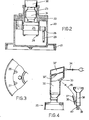
- Fig. 2 einen senkrechten Schnitt der Motorpumpengruppe;
- Fig. 3 einen Teil der Gruppe von oben gesehen mit besonderer Bezugnahme auf die Eingangs- und Ausgangsanschlüsse für das Fluid;
- Fig. 4 eine schematische Ansicht der mit dem auf dem Gerät montierten Fernbedienungsmittel verbundenen Gruppe.
- Figure 1 is a view of the device or tool, partly in section.
- Figure 2 is a vertical section of the motor pump group.
- Fig. 3 shows part of the group seen from above with particular reference to the inlet and outlet connections for the fluid;
- Fig. 4 is a schematic view of the group connected to the remote control means mounted on the device.
Das Gerät umfasst einen Stützteil 1, der in Ubereinstimmung seiner Enden 1', 1" die Stützen 2, 2' für die zu biegenden Rohre aufweist. Diese Stützen sind drehbar und verschiebbar gegenüber ihren im Stützteil 1 festen Zapfen 3, 3'.The device comprises a
Das Stützteil 1 ist ausserdem mit einem Handgriff 4 versehen, der aus zwei Teilen besteht, von denen der erste obere Teil 4' fest an dem Stützteil ist und der zweite zum ersten im wesentlichen koaxiale untere Teil 4" am ersten Teil beispielsweise durch Schrauben 5 befestigt ist. Im ersten Teil 4' des Handgriffes 4 hat eine mit einem Kolben 7 versehene Stange 6 ihren Sitz, wobei der dem Kolben 7 gegenüberliegende Teil der Stange 6 so ausgebildet ist, dass er die Befestigung eines Kopfes 6' ermöglicht, der in Form eines Stempels, durch eine axiale Verschiebung der Stange 6 nach aussen auf das bereits zuvor auf die entsprechenden Stützen 2, 2' angeordnete Rohr wirkt.The
Auf der ringförmigen Basis 7' des Kolbens 7 stützt sich eine vorgespannte Druckfeder 8 ab, die mit ihrem anderen Ende gegen eine am oberen Ende des zylindrischen Hoheraumes 4"" des Handgriffes bestehende is 4"' drückt.A
Der zweite, untere Teil 4" des Handgriffes 4 umfasst die im wesentlichen zueinander parallelen Rohrleitungen 9 und 11, die die entsprechenden Gewindelöcher 9', 11' zur Befestigung von Eingangs- bzw. Ausgangsschläuchen für ein Fluid (Flüssigkeit oder gegebenenfalls auch Druckluft) aufweisen, das vorzugsweise kontinuierlich im geschlossenen Kreislauf durch eine Pumpe gefördert wird.The second,
Bevor die Rohrleitung 9 die Basis des Kolbens 7 erreicht, schneidet oder verbindet sie sich mit der'zu den Leitungen 9, 11 im wesentlichen rechtwinkligen Rohrleitung 10, die ihrerseits mit der Ausgangsleitung 11 für das Fluid kommuniziert. In dem zur Rohrleitung 10 koaxialen Gewindeloch 10' hat ein Ventil 20 seinen Sitz, das unter der Wirkung des am Lager 14 angelenkten Hebels 13 axial verschiebbar ist, wobei dieses Lager in einem Stück mit dem zweiten Teil 4" des Griffes 4 gearbeitet ist. Der Hebel 13 wirkt auf den zum Stopfen 15 axial gleitenden Ventilschaft 12'.Before the
Das Ventil oder Drosselorgan 12, das in der Lage ist, einen wirklichen Durchlass der Strömung zu verhindern, ist der Wirkung einer Druckfeder 16 unterstellt, die im Innern der zylindrischen Leitung 10 untergebracht ist. Die Leitung 10 dient ausserdem zur Führung des äusseren Teils 12' des mit den Druchgangslöchern 12"" versehenen Ventils und zwar in jeder Stellung der axialen Verschiebung, in der sich das Ventil befindet. Das Ventil 12 weist ausserdem den geeigneterweise kegelstumpfförmigen Teller 12" auf, der genau dem im zweiten Teil des Griffes 4 befindlichen Sitz 17 angepasst ist.The valve or
Die Funktionsweise ist folgende:It works as follows:
Wenn sich das Gerät im stationären Zustand befindet, strömt das in dem dafür bestimmten Behälter aufgenommene Druckmittel unter der Wirkung der Pumpe frei durch die (in der Zeichnung nicht sichtbaren) Eingangs- und Ausgangsrohre und durch die Rohrleitungen 9, 10 und 11, wobei es gleichzeitig an die Basis des Kolbens ankommt und dabei den äusseren Teil 9" der Leitung 9 durchströmt. Um den freien Umlauf des Druckmittels zu ermöglichen, das in Bezug auf die Leitung 10 in axialer Richtung um die Feder 16 strömt, ist der zylindrische Teil 12", der das Ventil führt, mit Durchgangslöchern 12"" versehen, die einen entsprechenden Querschnitt aufweisen, um den freien Durchgang des Fluids in jeder Drehstellung, in der sich das Ventil befindet, zu gewährleisten.When the device is in the stationary state, the pressure medium accommodated in the container intended for this purpose flows freely under the action of the pump through the inlet and outlet pipes (not visible in the drawing) and through the
Wenn auf dem genannten Weg des Fluids die Geschwindigkeit oder der Umlauf der Strömung abnimmt oder durch die Verschiebebetätigung des Ventils 12, infolge der Betätigung des Hebels 13, unterbrochen wird, ergibt sich, dass der dem Ventil 12 vorgeschaltete Kolben 7 und mit ihm der Kopf 6' infolge einer Druckerhöhung, die sich nach dem Ventil einstellt, nach aussen geführt wird.If the speed or the circulation of the flow decreases or is interrupted by the displacement actuation of the
Wie aus den Figuren 2, 3 und 4 hervorgeht, umfasst die für das oben genannte Gerät vorgesehene Motorpumpengruppe eine Struktur 20, die aus einem Behälter besteht, der den Boden 21 und den Deckel 22 aufweist und von einem Hals 23 überragt wird. Unterhalb des Deckels 22 ist durch Schrauben 24 in stabiler Weise eine Pumpe 25 montiert, die in Ausserbetriebsstellung wenigstens teilweise im Fluid, vorzugsweise 01, eingetaucht ist und einen Eingangsanschluss zb (Fig. 3) bzw. einen Ausgangsanschluss 27, wie auch eine Offnung 28 (Fig. 2) aufweist; die mit einem Röhrchen 29 zum Ansaugen des Fluids am Boden des Behälters versehen ist.As can be seen from FIGS. 2, 3 and 4, the motor pump group provided for the above-mentioned device comprises a
Im hydraulischen Kreislauf ist ein regulierbares Sicherheitsventil für den Höchstdruck vorgesehen, welches auf dem Pumpenausgang und, mit Vorteil, im Innern des Behälters angebracht ist.An adjustable safety valve for the maximum pressure is provided in the hydraulic circuit, which is attached to the pump outlet and, advantageously, inside the tank.
Der Hals 23 dient zur Montage des Motors 30, der die Struktur überragt. Die Ubertragungskraft der Motorwelle wird der Pumpenwelle durch Einschaltung einer vorzugsweisen elastischen Kupplung 31 übertragen.The
Nach einer bevorzugten Verwirklichungsform besteht der Motor 30 aus einem im wesentlichen bekannten elektrischen Handbohrer 32 (Fig. 4). In seinem Handgriff 32', der vorteilhafterweise dazu dient, die Gruppe von Hand zu transportieren, ist eine zusätzliche Steuergruppe 33 elektronischer Art installiert und enthält einen in der Zeichnung nicht weiter dargestellten Transformator. Die Steuervorrichtung 33 ist mit einem Kabel 34, das mit dem Stromspannungsnetz verbindbar ist, sowie mit einem Kabel 35 zur Verbindung mit einem Schaltmittel 36 kleinen Ausmasses, das mit Niederspannung funktioniert, versehen. Vorteilhafterweise ist das Schaltmittel 36 zwischen dem Betätigungshebel 37 und dem Handgriff 38 des Werkzeuges angeordnet, sodass infolge der Betätigung des Hebels 37 dieser im wesentlichen in der gleichen Zeit auf den Motor der Pumpe wirkt und sie einschaltet oder ausschaltet.According to a preferred embodiment, the
Nach einer weiteren Verwirklichungsform ist vorgesehen, dass der Schalter 36 oder das Fernschaltmittel für die Pumpe in jedem anderen Teil des Handgriffes montiert werden kann, sofern er zwecks Betätigung leicht mit der Hand, die das Gerät hält, erreichbar ist. Ausser dem Kabel 35 können mit dem Gerät zwei Schläuche 39, 40 (Fig. 4) zum Zulauf und Rücklauf des Fluids verbunden werden, wobei diese biegsamen Schläuche mit ihrem anderen Ende mit den Anschlüssen 26 und 27 der Pumpe 25 verbunden sind.According to a further embodiment, it is provided that the
Der oben erwähnte Transformator hat den Zweck die vom Stromnetz gelieferte Spannung, zum Steuern des Motors, auf 6 Volt oder vorzugsweise auf 3 Volt zu erniedrigen, um dem Bedienungsmann die grösste Sicherheit zu gewährleisten.The purpose of the above-mentioned transformer is to reduce the voltage supplied by the mains for controlling the motor to 6 volts or preferably to 3 volts in order to ensure the greatest possible safety for the operator.
Der Fernschalter ist so vorgesehen, dass er sowohl an jedem Teil des Handgriffes als auch an jedem Teil der Motorpumpengruppe, unabhängig vom Vorhandensein des Steuerhebels (13) angebracht werden kann. Wenn beispielsweise die Motorpumpengruppe griffbereit für den Bedienungsmann angeordnet ist oder wenn sich eine Störung am Schalter 36 oder an der im Handgriff 32' des Elektrobohrers montierten Elektronischen Schaltung 33 ergibt, ist selbstverständlich das Funktionieren der Gruppe und damit des Werkzeuges von dem Vorhandensein des Hebelschalters 32" gewährleistet, mit dem die auf dem Markt befindlichen Handbohrer versehen sind.The remote switch is designed so that it can be attached to any part of the handle as well as to any part of the motor pump group, regardless of the presence of the control lever (13). If, for example, the motor pump group is arranged within easy reach of the operator or if there is a fault on the
Vorteilhafterweise besteht der Elektromotor aus einer Elektrohandbohrmaschine, die mit nicht wesentlichen Veränderungen der Motorpumpengruppe angepasst werden kann. Vorzugsweise ist die Verwendung einer Bohrmaschine vorgesehen, die beispielsweise mit Zwischenschaltung einer elastischen Kupplung in abnehmbarer Weise am Hals 23 oder am Deckel 22 mit an sich bekannten Befestigungsmitteln befestigt werden kann.The electric motor advantageously consists of an electric hand drill which can be adapted to the motor pump group with minor changes. The use of a drilling machine is preferably provided, which can be fastened, for example with the interposition of an elastic coupling, in a removable manner to the
In Fig. 4 ist das Mittel zur Fernsteuerung des Pumpenaggregats durch einen Schalter 36 kleinen Ausmasses dargestellt, der zwischen dem Steuerhebel 37 und dem Handgriff 38 des Werkzeuges angeordnet ist. Daraus ergibt sich, dass das Anlassen des Pumpenaggregates im wesentlichen gleichzeitig mit der Betätigung des Hebels erfolgt, während das Ausschalten des Aggregates dann automatisch erfolgt, wenn der Hebel infolge der Wirkung einer Feder in seine ursprüngliche Stellung gebracht wird.In Fig. 4 the means for remote control of the pump unit is shown by a
Als Fernsteuerungsmittel für den Motor ist die Verwendung an sich bekannter hydrostatischer Organe vorgesehen; die vorzugsweise unter der Wirkung des auf dem Gerät vorgesehenen Steuerhebels 13 eine gewisse, zum Betätigen des Schalters, der in diesem Falle vorteilhafterweise auf der Motorpumpengruppe angeordnet ist, ausreichende Fluidmenge zusammenpressen kann.As a remote control means for the engine, the use of known hydrostatic organs is provided; which, preferably under the action of the
Nach einer weiteren Verwirklichungsform ist eine Fernsteuerung bekannter Art vorgesehen, die aus einem biegsamen Mittel besteht, das sowohl einem Zug als auch einer Kompression unterzogen werden kann und, wenn es von dem oben genannten Hebel betätigt wird, auf das Schaltmittel des Motors zum Betätigen der Pumpe einwirkt. Schliesslich wird auch eine Elektronen Fernsteuerung in Betracht gezogen. Ausserdem ist das Vorhandensein eines vorzugsweise auf der Ausgangsrohrleitung des Gerätes montierten Elektroventils vorgesehen, das durch einen Druckknopf auf dem Handgriff des Gerätes fernbetätigt wird.According to a further embodiment, a remote control of known type is provided, which consists of a flexible means which can be subjected to both a pull and a compression and, when actuated by the above-mentioned lever, to the switching means of the motor for actuating the pump acts. Finally, remote electron control is also being considered. In addition, the presence of an electrovalve, which is preferably mounted on the outlet pipeline of the device, is provided and is remotely operated by a push button on the handle of the device.
Claims (14)
Applications Claiming Priority (2)
| Application Number | Priority Date | Filing Date | Title |
|---|---|---|---|
| IT22652/78A IT1095305B (en) | 1978-04-24 | 1978-04-24 | MOTOR-PUMP UNIT AND HALF FOR ITS REMOTE OPERATION |
| IT2265278 | 1978-04-24 |
Publications (3)
| Publication Number | Publication Date |
|---|---|
| EP0004858A2 true EP0004858A2 (en) | 1979-10-31 |
| EP0004858A3 EP0004858A3 (en) | 1979-12-12 |
| EP0004858B1 EP0004858B1 (en) | 1983-11-16 |
Family
ID=11198875
Family Applications (1)
| Application Number | Title | Priority Date | Filing Date |
|---|---|---|---|
| EP79100531A Expired EP0004858B1 (en) | 1978-04-24 | 1979-02-23 | Bending apparatus for tubes |
Country Status (5)
| Country | Link |
|---|---|
| US (1) | US4299113A (en) |
| EP (1) | EP0004858B1 (en) |
| CA (1) | CA1144054A (en) |
| DK (1) | DK94779A (en) |
| IT (1) | IT1095305B (en) |
Cited By (1)
| Publication number | Priority date | Publication date | Assignee | Title |
|---|---|---|---|---|
| EP0536632A1 (en) * | 1991-10-09 | 1993-04-14 | C.B.C. S.p.A. | Pipe bending machine with an auxiliary mechanism for performing supplementary operations |
Families Citing this family (4)
| Publication number | Priority date | Publication date | Assignee | Title |
|---|---|---|---|---|
| US4494398A (en) * | 1983-02-14 | 1985-01-22 | Midas International Corporation | Tubing expander apparatus |
| US4967585A (en) * | 1989-06-12 | 1990-11-06 | Samuel Grimaldo | Bending die and ram assembly for tube bending machine |
| US5615572A (en) * | 1995-01-12 | 1997-04-01 | Hunjohn, Inc. | Hydraulic tube bender |
| JP4839188B2 (en) * | 2006-11-21 | 2011-12-21 | 株式会社ジャパーナ | Golf club shaft angle adjuster |
Citations (19)
| Publication number | Priority date | Publication date | Assignee | Title |
|---|---|---|---|---|
| US2132112A (en) * | 1936-03-06 | 1938-10-04 | Huxon Holding Corp | Riveting mechanism |
| US2255985A (en) * | 1939-11-27 | 1941-09-16 | Blackhawk Mfg Co | Pipe bending assemblage |
| US2329709A (en) * | 1940-11-23 | 1943-09-21 | Chicago Pneumatic Tool Co | Hydraulic riveter |
| US2356366A (en) * | 1942-12-04 | 1944-08-22 | Hydraulic Machinery Inc | Power transmission |
| US2464459A (en) * | 1946-10-31 | 1949-03-15 | Marietta Mfg Company | Pipe-bending machine |
| US2845826A (en) * | 1951-08-22 | 1958-08-05 | Chicago Pneumatic Tool Co | Riveting machine for simultaneously driving rivets in opposite sides of car or other like constructions |
| FR1257737A (en) * | 1960-02-23 | 1961-04-07 | Bending machine improvements | |
| US3001548A (en) * | 1959-06-10 | 1961-09-26 | Huck Mfg Co | Apparatus for driving lockbolts and the like |
| US3074350A (en) * | 1959-01-06 | 1963-01-22 | R C Ray | Portable pump with interchangeable drive unit |
| GB931193A (en) * | 1959-09-26 | 1963-07-10 | Hydrodyn Ag | Improvements in or relating to multi-purpose apparatus |
| FR1430039A (en) * | 1965-04-22 | 1966-02-25 | Huck Mfg Co | Tool to set rivets by necking |
| US3253450A (en) * | 1962-12-27 | 1966-05-31 | Combustion Eng | Portable tube bender |
| FR1472663A (en) * | 1966-03-25 | 1967-03-10 | Festo Maschf Stoll G | Single-acting cylinder for pressurized pneumatic fluids |
| AU3002667A (en) * | 1968-01-02 | 1969-07-10 | Dempster Harry | Hybrid recorder |
| US3456561A (en) * | 1967-09-25 | 1969-07-22 | William Laikam Jr | Air pressure actuated cylinder unit |
| DE1538910A1 (en) * | 1966-10-08 | 1970-03-26 | Licentia Gmbh | Electric motor drive unit |
| DE2020005A1 (en) * | 1970-04-24 | 1971-11-11 | Koss Ohg Walter | Pneumatically operated tool |
| US3924438A (en) * | 1974-09-23 | 1975-12-09 | Greenlee Bros & Co | Hydraulic cable bender |
| FR2306027A1 (en) * | 1975-04-03 | 1976-10-29 | Mec Flli Caporuss Off | PORTABLE HYDRAULIC UNIT WITH MANUAL CONTROL FOR BENDING TUBES |
Family Cites Families (6)
| Publication number | Priority date | Publication date | Assignee | Title |
|---|---|---|---|---|
| CA458280A (en) * | 1949-07-26 | Howard Edge Stanley | Hydraulic control mechanism | |
| US2867261A (en) * | 1955-02-23 | 1959-01-06 | Blackhawk Mfg Co | Pipe bender with bend indicator means on pivotal reaction blocks |
| US2998838A (en) * | 1959-07-23 | 1961-09-05 | Jr Berry Lorenz Byrd | Pipe bending rack |
| US3213605A (en) * | 1964-02-28 | 1965-10-26 | Welden Andrew Jackson | Fluid actuated mechanism |
| US3344635A (en) * | 1964-04-28 | 1967-10-03 | Greenlee Bros & Co | Pipe benders |
| US3620066A (en) * | 1969-06-25 | 1971-11-16 | Neville T Henkel | Metal bending method and machine therefor |
-
1978
- 1978-04-24 IT IT22652/78A patent/IT1095305B/en active
-
1979
- 1979-02-23 EP EP79100531A patent/EP0004858B1/en not_active Expired
- 1979-03-05 CA CA000322765A patent/CA1144054A/en not_active Expired
- 1979-03-05 US US06/017,300 patent/US4299113A/en not_active Expired - Lifetime
- 1979-03-07 DK DK94779A patent/DK94779A/en not_active Application Discontinuation
Patent Citations (19)
| Publication number | Priority date | Publication date | Assignee | Title |
|---|---|---|---|---|
| US2132112A (en) * | 1936-03-06 | 1938-10-04 | Huxon Holding Corp | Riveting mechanism |
| US2255985A (en) * | 1939-11-27 | 1941-09-16 | Blackhawk Mfg Co | Pipe bending assemblage |
| US2329709A (en) * | 1940-11-23 | 1943-09-21 | Chicago Pneumatic Tool Co | Hydraulic riveter |
| US2356366A (en) * | 1942-12-04 | 1944-08-22 | Hydraulic Machinery Inc | Power transmission |
| US2464459A (en) * | 1946-10-31 | 1949-03-15 | Marietta Mfg Company | Pipe-bending machine |
| US2845826A (en) * | 1951-08-22 | 1958-08-05 | Chicago Pneumatic Tool Co | Riveting machine for simultaneously driving rivets in opposite sides of car or other like constructions |
| US3074350A (en) * | 1959-01-06 | 1963-01-22 | R C Ray | Portable pump with interchangeable drive unit |
| US3001548A (en) * | 1959-06-10 | 1961-09-26 | Huck Mfg Co | Apparatus for driving lockbolts and the like |
| GB931193A (en) * | 1959-09-26 | 1963-07-10 | Hydrodyn Ag | Improvements in or relating to multi-purpose apparatus |
| FR1257737A (en) * | 1960-02-23 | 1961-04-07 | Bending machine improvements | |
| US3253450A (en) * | 1962-12-27 | 1966-05-31 | Combustion Eng | Portable tube bender |
| FR1430039A (en) * | 1965-04-22 | 1966-02-25 | Huck Mfg Co | Tool to set rivets by necking |
| FR1472663A (en) * | 1966-03-25 | 1967-03-10 | Festo Maschf Stoll G | Single-acting cylinder for pressurized pneumatic fluids |
| DE1538910A1 (en) * | 1966-10-08 | 1970-03-26 | Licentia Gmbh | Electric motor drive unit |
| US3456561A (en) * | 1967-09-25 | 1969-07-22 | William Laikam Jr | Air pressure actuated cylinder unit |
| AU3002667A (en) * | 1968-01-02 | 1969-07-10 | Dempster Harry | Hybrid recorder |
| DE2020005A1 (en) * | 1970-04-24 | 1971-11-11 | Koss Ohg Walter | Pneumatically operated tool |
| US3924438A (en) * | 1974-09-23 | 1975-12-09 | Greenlee Bros & Co | Hydraulic cable bender |
| FR2306027A1 (en) * | 1975-04-03 | 1976-10-29 | Mec Flli Caporuss Off | PORTABLE HYDRAULIC UNIT WITH MANUAL CONTROL FOR BENDING TUBES |
Non-Patent Citations (1)
| Title |
|---|
| JOHN J. PIPPENGER: " Fluid-power Controls", 1959, McGraw-Hill Book, Comp. Inc., London, Seiten 75 bis 77 * SEITE 77; FIGUR 7-4 * * |
Cited By (1)
| Publication number | Priority date | Publication date | Assignee | Title |
|---|---|---|---|---|
| EP0536632A1 (en) * | 1991-10-09 | 1993-04-14 | C.B.C. S.p.A. | Pipe bending machine with an auxiliary mechanism for performing supplementary operations |
Also Published As
| Publication number | Publication date |
|---|---|
| DK94779A (en) | 1979-10-25 |
| US4299113A (en) | 1981-11-10 |
| EP0004858B1 (en) | 1983-11-16 |
| IT7822652A0 (en) | 1978-04-24 |
| IT1095305B (en) | 1985-08-10 |
| EP0004858A3 (en) | 1979-12-12 |
| CA1144054A (en) | 1983-04-05 |
Similar Documents
| Publication | Publication Date | Title |
|---|---|---|
| DE2756561A1 (en) | DRIVE DEVICE FOR MOVING A MOVABLE BODY IN A TUBULAR CHANNEL | |
| DE1576088B2 (en) | QUICK RELEASE VALVE FOR HYDRAULIC POWER CYLINDERS | |
| DE2532408A1 (en) | PNEUMATICALLY OPERATED DEVICE | |
| EP0004858A2 (en) | Bending apparatus for tubes | |
| DE4301179C2 (en) | Process for operating a pipe cleaning machine and pipe cleaning machine for performing the method | |
| EP3031539A1 (en) | Bending device | |
| WO2002044508A2 (en) | Pneumatic rock-boring device and method for horizontal drilling using compressed air and drilling medium | |
| DE2824074A1 (en) | Hydraulically operated pipe bending tool - has plunger operated by closed circuit fluid pressure increase following manual valve closure | |
| EP1157755A2 (en) | Nozzle manifold for the cooling or descaling of metallic elongated material, in particular of rolling stock | |
| DE202008000318U1 (en) | Needle valve nozzle with improved lever articulation | |
| DE2617925C3 (en) | Lubrication system for lubricating a wide variety of compressed air consumers | |
| DE1484393B1 (en) | DRILLING DEVICE FOR EXTENDING THE SOLE OF A DRILLING HOLE | |
| DE202019100714U1 (en) | Fitting for drilling a pipe and / or shutting off a pipe connection on a pipe | |
| EP0198896B1 (en) | Device for connecting a boring line with a tube or similar item | |
| DE10041840A1 (en) | tapping | |
| DE2928255A1 (en) | Pressurised hot-water generator for mobile cleaning unit - has parallel non-return valves working in opposite directions between pump and heater | |
| DE102006001825B4 (en) | metering valve | |
| DE3221036C2 (en) | Device for shutting off and ventilating a pipeline | |
| DE3117149C2 (en) | Pneumatic impact tool | |
| DE2616523C2 (en) | Device for expanding pipe ends within a pipe disc | |
| DE3230759C2 (en) | Device for trenchless pipe laying | |
| DE10213803B4 (en) | Tapping system for house connection cables | |
| DE2245240C3 (en) | Distributor serving as a switching device for reversing a two-line central lubrication system | |
| DE602872C (en) | Automatic control device for liquid containers, especially for compressed air accumulators | |
| AT224996B (en) | Device for lubricating control valves or other objects with moving parts |
Legal Events
| Date | Code | Title | Description |
|---|---|---|---|
| PUAI | Public reference made under article 153(3) epc to a published international application that has entered the european phase |
Free format text: ORIGINAL CODE: 0009012 |
|
| PUAL | Search report despatched |
Free format text: ORIGINAL CODE: 0009013 |
|
| AK | Designated contracting states |
Designated state(s): BE CH FR GB LU NL SE |
|
| AK | Designated contracting states |
Designated state(s): BE CH FR GB LU NL SE |
|
| 17P | Request for examination filed | ||
| GRAA | (expected) grant |
Free format text: ORIGINAL CODE: 0009210 |
|
| AK | Designated contracting states |
Designated state(s): BE CH FR GB LU NL SE |
|
| ET | Fr: translation filed | ||
| PG25 | Lapsed in a contracting state [announced via postgrant information from national office to epo] |
Ref country code: LU Free format text: LAPSE BECAUSE OF NON-PAYMENT OF DUE FEES Effective date: 19840229 |
|
| PGFP | Annual fee paid to national office [announced via postgrant information from national office to epo] |
Ref country code: FR Payment date: 19840229 Year of fee payment: 6 |
|
| PGFP | Annual fee paid to national office [announced via postgrant information from national office to epo] |
Ref country code: LU Payment date: 19840328 Year of fee payment: 6 |
|
| PGFP | Annual fee paid to national office [announced via postgrant information from national office to epo] |
Ref country code: NL Payment date: 19840330 Year of fee payment: 6 Ref country code: CH Payment date: 19840330 Year of fee payment: 6 |
|
| PGFP | Annual fee paid to national office [announced via postgrant information from national office to epo] |
Ref country code: SE Payment date: 19840331 Year of fee payment: 6 |
|
| PGFP | Annual fee paid to national office [announced via postgrant information from national office to epo] |
Ref country code: BE Payment date: 19840630 Year of fee payment: 6 |
|
| PLBE | No opposition filed within time limit |
Free format text: ORIGINAL CODE: 0009261 |
|
| STAA | Information on the status of an ep patent application or granted ep patent |
Free format text: STATUS: NO OPPOSITION FILED WITHIN TIME LIMIT |
|
| 26N | No opposition filed | ||
| PG25 | Lapsed in a contracting state [announced via postgrant information from national office to epo] |
Ref country code: SE Effective date: 19850224 |
|
| PG25 | Lapsed in a contracting state [announced via postgrant information from national office to epo] |
Ref country code: CH Effective date: 19850228 Ref country code: BE Effective date: 19850228 |
|
| BERE | Be: lapsed |
Owner name: L. ID. IT DEI F.LLI BELOTTI Effective date: 19850223 |
|
| PG25 | Lapsed in a contracting state [announced via postgrant information from national office to epo] |
Ref country code: NL Effective date: 19850901 |
|
| GBPC | Gb: european patent ceased through non-payment of renewal fee | ||
| NLV4 | Nl: lapsed or anulled due to non-payment of the annual fee | ||
| PG25 | Lapsed in a contracting state [announced via postgrant information from national office to epo] |
Ref country code: FR Free format text: LAPSE BECAUSE OF NON-PAYMENT OF DUE FEES Effective date: 19851031 |
|
| REG | Reference to a national code |
Ref country code: CH Ref legal event code: PL |
|
| REG | Reference to a national code |
Ref country code: FR Ref legal event code: ST |
|
| PG25 | Lapsed in a contracting state [announced via postgrant information from national office to epo] |
Ref country code: GB Effective date: 19881117 |
|
| EUG | Se: european patent has lapsed |
Ref document number: 79100531.7 Effective date: 19860129 |