EP3180984A1 - Cooking device - Google Patents
Cooking device Download PDFInfo
- Publication number
- EP3180984A1 EP3180984A1 EP16193563.0A EP16193563A EP3180984A1 EP 3180984 A1 EP3180984 A1 EP 3180984A1 EP 16193563 A EP16193563 A EP 16193563A EP 3180984 A1 EP3180984 A1 EP 3180984A1
- Authority
- EP
- European Patent Office
- Prior art keywords
- cooking appliance
- closure element
- water tank
- open position
- filling device
- Prior art date
- Legal status (The legal status is an assumption and is not a legal conclusion. Google has not performed a legal analysis and makes no representation as to the accuracy of the status listed.)
- Granted
Links
- 238000010411 cooking Methods 0.000 title claims abstract description 55
- XLYOFNOQVPJJNP-UHFFFAOYSA-N water Substances O XLYOFNOQVPJJNP-UHFFFAOYSA-N 0.000 claims abstract description 62
- 238000007599 discharging Methods 0.000 claims 1
- 239000000443 aerosol Substances 0.000 description 5
- 239000007788 liquid Substances 0.000 description 4
- 230000008878 coupling Effects 0.000 description 3
- 238000010168 coupling process Methods 0.000 description 3
- 238000005859 coupling reaction Methods 0.000 description 3
- 239000012530 fluid Substances 0.000 description 3
- 238000000034 method Methods 0.000 description 3
- 238000005429 filling process Methods 0.000 description 2
- 230000007246 mechanism Effects 0.000 description 2
- 230000004308 accommodation Effects 0.000 description 1
- 238000011109 contamination Methods 0.000 description 1
- 230000005574 cross-species transmission Effects 0.000 description 1
- 230000018044 dehydration Effects 0.000 description 1
- 238000006297 dehydration reaction Methods 0.000 description 1
- 230000001419 dependent effect Effects 0.000 description 1
- 238000011161 development Methods 0.000 description 1
- 230000018109 developmental process Effects 0.000 description 1
- 239000008236 heating water Substances 0.000 description 1
- 238000003780 insertion Methods 0.000 description 1
- 230000037431 insertion Effects 0.000 description 1
- 238000009434 installation Methods 0.000 description 1
- 238000002955 isolation Methods 0.000 description 1
- 239000000463 material Substances 0.000 description 1
- 239000003595 mist Substances 0.000 description 1
- 239000000203 mixture Substances 0.000 description 1
- 238000003032 molecular docking Methods 0.000 description 1
- 230000002093 peripheral effect Effects 0.000 description 1
- 239000000126 substance Substances 0.000 description 1
- 239000008400 supply water Substances 0.000 description 1
Images


Classifications
-
- A—HUMAN NECESSITIES
- A21—BAKING; EDIBLE DOUGHS
- A21B—BAKERS' OVENS; MACHINES OR EQUIPMENT FOR BAKING
- A21B3/00—Parts or accessories of ovens
- A21B3/04—Air-treatment devices for ovens, e.g. regulating humidity
-
- F—MECHANICAL ENGINEERING; LIGHTING; HEATING; WEAPONS; BLASTING
- F24—HEATING; RANGES; VENTILATING
- F24C—DOMESTIC STOVES OR RANGES ; DETAILS OF DOMESTIC STOVES OR RANGES, OF GENERAL APPLICATION
- F24C15/00—Details
- F24C15/003—Details moisturising of air
-
- F—MECHANICAL ENGINEERING; LIGHTING; HEATING; WEAPONS; BLASTING
- F24—HEATING; RANGES; VENTILATING
- F24C—DOMESTIC STOVES OR RANGES ; DETAILS OF DOMESTIC STOVES OR RANGES, OF GENERAL APPLICATION
- F24C15/00—Details
- F24C15/32—Arrangements of ducts for hot gases, e.g. in or around baking ovens
- F24C15/322—Arrangements of ducts for hot gases, e.g. in or around baking ovens with forced circulation
- F24C15/327—Arrangements of ducts for hot gases, e.g. in or around baking ovens with forced circulation with air moisturising
Definitions
- the present invention relates to a cooking appliance, in particular steam cooking appliance, with a cooking chamber which can be closed by a door, a control panel and a water tank arranged outside the cooking chamber, which is fluidically coupled to a filling device arranged in the panel.
- Cooking appliances such as ovens, microwave ovens, Dampfgarieri etc. are known from the prior art. Steam cooking appliances, for example, can be divided into steamers, steam ovens, steam cookers and ovens with a steam function.
- Cooking appliances in particular ovens, can be equipped with an additional steam function to improve the cooking results or be executed directly as a steamer.
- the systems available on the market can generate steam by heating water, which is then subsequently introduced into a muffle of the cooking appliance.
- a cooking appliance with an additional aerosol function Another possibility for introducing moisture / liquid into a cooking chamber is a cooking appliance with an additional aerosol function.
- aerosol can be produced in the form of a fine aerosol mist, which can then be provided in a cooking chamber of the cooking appliance.
- the device for generating and introducing aerosol is designed such that a liquid can be atomized into the smallest droplets. The droplets are able to transport additional substances without destroying them. In contrast to a steam cooker or an oven with steam function, the liquid does not need to be heated.
- a container for a working fluid such as water.
- a water tank in which the water, which is then to be vaporized / atomized, can be reversibly removed and replaced.
- Systems are also known in which the water tank can be pulled out from the front of the steam cooking appliance and pushed back in again.
- a cooking appliance with a removable tank is for example from the EP 2 363 057 A1 known, which has a closable with a door cooking chamber, a control panel and a drawer-like hold Erten storage tank for a working fluid.
- a water tank is firmly integrated in the device and not removable.
- Such devices thus require a filling device which is fluidically coupled to the water tank.
- this type of device does not allow you to empty the water from the built-in tank.
- the filling mechanisms disclosed in the prior art are only capable of directing water to the water tank during the filling process.
- a cooking appliance with the features of claim 1.
- this can be achieved in a cooking appliance according to the preamble of claim 1, characterized in that the filling device has a closure element, which in a first open position for filling water and a second opening position for emptying water from the water tank can be brought. It is thus not necessary that the water tank must be arranged in close proximity to the panel.
- the closure element of the filling device can be integrated into the panel in an advantageous manner.
- a significant advantage is further that in or behind the aperture no complex sliding and / or coupling mechanism with water-bearing parts must be provided. This can lead to a reduced complexity and thus to a cost saving.
- the cooking appliance according to the invention can be any type of cooking appliance which has a container located in the appliance for storing a working liquid, for example water.
- the cooking appliance is, but not limited to, a steam cooker, a steam cooker, an aerosol cooker, or the like.
- the water tank may be located at any suitable mounting position within a housing of the cooking appliance.
- the fluidic coupling between the filling device and the water tank may include or may be formed by conduits, valves, pumps and / or the like in a non-limiting manner.
- further devices are provided in order, for example, to supply the water in the case of a steam cooking appliance from the water tank to an evaporator unit.
- this type of device is well known to those of ordinary skill in the art, so a detailed description thereof will be omitted for the sake of clarity.
- the filling device may further comprise a holder for coupling the same with the closure element.
- other elements such as fastening means for securing the filling device to or in the aperture may be included.
- the diaphragm may have a recess adapted to the closure element for receiving the same. It can be provided that the closure element of the filling device in contrast to a cooking appliance with removable water tank can not be solved without installation effort of the filling device. Furthermore, it can be provided that the closure element when reaching the two open positions in each case latched in the filling device, so that, for example, it is clear to a user / user that he has reached a certain opening position. This means that each of the two open positions is associated with a defined latching step, in which the closure element is held locked relative to the filling device.
- the second open position which is different from the first open position, is reached only after passing through the first open position. That is, when bringing the shutter member into the second open position, the shutter member is first brought into the first open position with respect to an opening direction thereof and then reaches the second open position after passing through the first open position. As a result, when the second opening position has been reached, the closure element has traveled a greater travel path than after reaching the first open position in the same direction of movement.
- a user can bring the closure element of the filling device, for example, from a closed position in which the closure element is in a non-actuated state, first in the first open position, for example, to supply water into the filling device.
- the closure element can now be returned to its closed position.
- the user brings the closure element in the second open position by performing an opening movement in which the closure element first passes through the first open position and then after passing through the first Opening position in same direction- reaches the second open position for emptying the water from the water tank.
- the closure element has an outer wall formed as a front part, which is in a closed position substantially flush with the panel.
- the closure element can be brought from its closed position into one of the open positions by a push-pull function.
- the push-pull function is one way to bring the closure element into an open position, but the present invention is not limited thereto.
- the push-pull function can be dispensed with a handle, a handle or a similar means for moving the closure element from its closed position, which, for example, does not interfere with the design of the panel.
- a movement of the closure element would also be conceivable to move the same at least partially by motor from the closed position into one of the two open positions.
- the closure element has a receiving space, on the underside of which a connection part for connection to the water tank is arranged.
- a connection part for connection to the water tank is arranged.
- a pump is provided for emptying the water tank.
- the pump By means of the pump, the water can be returned from the water tank to the closure element in a simple manner.
- the pump is switched on only in the second open position.
- the closure element in the designated second opening position ie a position for emptying the water from the water tank.
- the pump is switched on automatically when the second opening position is reached.
- suitable components for automatic turn-on such as a position sensor, relays, and / or the like, will be provided.
- the closure element is formed by a pivotable flap.
- a robust and stable embodiment of the closure element can be realized.
- this embodiment may allow the filled water to drain substantially completely into the water tank.
- the flap can still be securely attached to the filling device, which also improves the feel when operating the same.
- the pivotable flap is pivotable about a horizontal pivot axis.
- the horizontal pivot axis is preferably in depth direction behind the aperture, so that the flap can be fully integrated in the panel in an advantageous manner.
- the invention is not limited thereto and it is also conceivable that the closure element pivots / rotates like a laterally hinged door about a vertical pivot axis.
- the closure element may be provided, for example, that the closure element is formed by a hollow half-cylinder, whose planar peripheral surface forms the outer wall formed as a front part.
- the outer wall formed as a front part is inclined in a range of 30 ° to 60 °, in particular 40 ° to 50 ° in relation to a plane formed by the diaphragm in the first open position and in the second opening position is inclined in a range of 100 ° to 130 °, in particular 110 ° to 120 °.
- Fig. 1 is shown in a simplified schematic representation of an inventive cooking appliance, which has a cooking chamber 4.
- the cooking chamber 4 is delimited by a muffle 2, wherein a feed opening is formed on the front side, which can be closed by a door 5.
- the door 5 has on its outside a handle 7.
- food can be introduced and prepared.
- the cooking appliance has an aperture 8 arranged on an upper region of the cooking appliance. In the aperture 8 are controls in the form of rotating control knobs.
- a filling device 10 is arranged in a side region of the aperture 8, which is fluidically coupled to a water tank (not shown).
- a working fluid filled with water, for example.
- the filling device 10 has a closure element 12.
- the closure element 12 comprises an outer wall 14 formed as a front part, which in the closed position S shown is substantially flush with the panel 8.
- the closure element 12 can be brought from its closed position S into an open position B or E by a push-pull function.
- a pump (not shown) is provided in the cooking appliance, which is automatically turned on reaching a second open position to empty the water from the water tank.
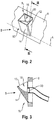
- Fig. 2 shows a perspective view of the filling device 10 of Fig. 1 represents in a first opening position B.
- the closure element 12 of the filling device 10 is formed by a substantially pocket-shaped flap which is pivotable about a pivot axis A.
- the pivot axis A is arranged in the depth direction of the cooking appliance behind the aperture 8 in order to fully integrate the filling device 10 in the aperture 8 can.
- the filling device 10 is arranged within a diaphragm recess 9 of the diaphragm 8. Between the diaphragm recess 9 and the closure element 12 of the filling device 10 is a small air gap, so that the closure element 12 is easily movable within this aperture recess 9.
- the pivotable flap formed as a closure element 12 has an outer wall 14, which is pivoted in the illustrated first open position relative to the diaphragm by about 40 ° in the direction of a user, ie opposite to the Bautiefencardi.
- the flap has a receiving space 16, on the underside of a connection part 20 is provided, on which a pipe 22 is pushed. By means of the pipe 22, the filling device 10 is fluidly connected to the water tank.
- Fig. 3 shows a schematic sectional view of the filling device 10 of Fig. 2 along the line III-III. How out Fig. 3 it can be seen, the flap formed as a closure element 12 is pivoted so far in the first open position that filled water can flow without residue on the connection part 20 in the pipe 22.
- Fig. 4 shows a perspective view of the filling device 10 of Fig. 1 schematically represents in the second open position E according to the embodiment of the present invention. Unlike the in Fig. 2 shown first opening position B can be emptied water from the water tank to the outside of the cooking appliance in the illustrated second opening position.
- Fig. 5 shows a schematic sectional view of the filling device 10 of Fig. 4 along the line VV. How out Fig. 5 it can be seen, in the second open position, the water can be completely discharged via the flap in a container (not shown). In the present case, the outer wall 14 of the flap is pivoted relative to the diaphragm by about 120 °.
Abstract
Die vorliegende Erfindung betrifft ein Gargerät, insbesondere Dampfgargerät, mit einem durch eine Tür (5) verschließbaren Garraum (4), einer Bedienblende (8) und einem außerhalb des Garraums (4) angeordneten Wassertank, der mit einer in der Blende (8) angeordneten Einfüllvorrichtung (10) fluidisch gekoppelt ist. Die Einfüllvorrichtung (10) weist ein Verschlusselement (12) auf, das in eine erste Öffnungsstellung (B) zum Einfüllen von Wasser und eine zweite Öffnungsstellung (E) zum Entleeren von Wasser aus dem Wassertank bringbar ist.The present invention relates to a cooking appliance, in particular Dampfgargerät, with a by a door (5) closable cooking chamber (4), a control panel (8) and a outside of the cooking chamber (4) arranged water tank arranged with a in the aperture (8) Filling device (10) is fluidically coupled. The filling device (10) has a closure element (12) which can be brought into a first open position (B) for filling in water and a second open position (E) for emptying water out of the water tank.
Description
Die vorliegende Erfindung betrifft ein Gargerät, insbesondere Dampfgargerät, mit einem durch eine Tür verschließbaren Garraum, einer Bedienblende und einem außerhalb des Garraums angeordneten Wassertank, der mit einer in der Blende angeordneten Einfüllvorrichtung fluidisch gekoppelt ist.The present invention relates to a cooking appliance, in particular steam cooking appliance, with a cooking chamber which can be closed by a door, a control panel and a water tank arranged outside the cooking chamber, which is fluidically coupled to a filling device arranged in the panel.
Aus dem Stand der Technik sind Gargeräte wie beispielsweise Backöfen, Mikrowellengeräte, Dampfgargeräte usw. bekannt. Dabei können Dampfgargeräte zum Beispiel in Dampfgarer, Dampfbacköfen, Dampfkochmulden und Backöfen mit einer Dampffunktion unterteilt werden.Cooking appliances such as ovens, microwave ovens, Dampfgargeräte etc. are known from the prior art. Steam cooking appliances, for example, can be divided into steamers, steam ovens, steam cookers and ovens with a steam function.
Gargeräte, insbesondere Backöfen, können zur Verbesserung des Garergebnisses mit einer zusätzlichen Dampfunktion ausgestattet oder direkt als Dampfgarer ausgeführt werden. Dabei können die auf dem Markt verfügbaren Systeme durch Erhitzen von Wasser Dampf erzeugen, der dann anschließend in eine Muffel des Gargeräts eingetragen wird. Durch die Zuführung von Dampf kann beispielsweise die Austrocknung verhindert oder die Bräunung eines Garguts verbessert werden.Cooking appliances, in particular ovens, can be equipped with an additional steam function to improve the cooking results or be executed directly as a steamer. The systems available on the market can generate steam by heating water, which is then subsequently introduced into a muffle of the cooking appliance. By supplying steam, for example, dehydration can be prevented or the browning of a food can be improved.
Eine weitere Möglichkeit zum Eintragen von Feuchtigkeit/Flüssigkeit in einen Garraum stellt ein Gargerät mit einer zusätzlichen Aerosol-Funktion dar. Mithilfe dieser Funktion kann Aerosol in Form eines feinen Aerosolnebels erzeugt werden, der dann in einen Garraum des Gargeräts bereitstellbar ist. Die Vorrichtung zum Erzeugen und Eintragen von Aerosol ist derart eingerichtet, dass eine Flüssigkeit in kleinste Tröpfchen zerstäubt werden kann. Die Tröpfchen sind in der Lage, zusätzliche Stoffe zu transportieren, ohne dass diese zerstört werden. Im Gegensatz zu einem Dampfgargerät oder einem Backofen mit Dampffunktion braucht die Flüssigkeit nicht erwärmt werden.Another possibility for introducing moisture / liquid into a cooking chamber is a cooking appliance with an additional aerosol function. With this function, aerosol can be produced in the form of a fine aerosol mist, which can then be provided in a cooking chamber of the cooking appliance. The device for generating and introducing aerosol is designed such that a liquid can be atomized into the smallest droplets. The droplets are able to transport additional substances without destroying them. In contrast to a steam cooker or an oven with steam function, the liquid does not need to be heated.
Zum Betrieb der zuvor genannten Geräte ist es erforderlich, einen Behälter für eine Betriebsflüssigkeit, beispielsweise Wasser vorzusehen. Bei einigen Ausführungen kann vorgesehen sein, dass ein Wassertank, in dem das Wasser, welches dann verdampft/vernebelt werden soll, reversibel entnommen und wieder eingesetzt werden kann. Dabei sind auch Systeme bekannt, bei denen der Wassertank frontseitig des Dampfgargeräts herausgezogen und wieder eingeschoben werden kann.To operate the aforementioned devices, it is necessary to provide a container for a working fluid, such as water. In some embodiments, it may be provided that a water tank in which the water, which is then to be vaporized / atomized, can be reversibly removed and replaced. Systems are also known in which the water tank can be pulled out from the front of the steam cooking appliance and pushed back in again.
Bei den gegenwärtig bekannten Ausgestaltungen mit einschiebbarem und entnehmbarem Wassertank kann es aufgrund der Ausgestaltungen für einen Nutzer relativ aufwendig sein, den Entnahmevorgang und insbesondere den Einführvorgang durchzuführen. Dabei können sich Verspreizungen oder Verklemmungen ergeben. Dadurch kann auch ein Überschwappen des Wassers in dem Tank erfolgen, so dass auch diesbezüglich ein Herauslaufen und Verunreinigung der Umgebung auftreten kann. Darüber hinaus ist bei bekannten Systemen nach dem Herausziehen ein Austropfen aus dem Andockstutzen des Wassertanks auf den Boden oder eine Gerätevorderseite vorkommend.In the currently known embodiments with retractable and removable water tank, it may be relatively complicated due to the configurations for a user to carry out the removal process and in particular the insertion process. This can result in misalignments or jamming. As a result, a spillover of the water in the tank can take place, so that in this regard can run out and contamination of the environment. In addition, in known systems after pulling out a dripping from the docking of the water tank on the ground or a front of the device occurring.
Ein Gargerät mit einem entnehmbaren Tank ist beispielsweise aus der
Darüber hinaus kann bei anderen bekannten Ausgestaltungen vorgesehen sein, dass ein Wassertank fest in dem Gerät integriert und nicht entnehmbar ist. Derartige Geräte benötigen somit eine Einfüllvorrichtung, die mit dem Wassertank fluidisch gekoppelt ist. Im Gegensatz zu den Geräten mit entnehmbaren Wassertank ist es bei dieser Art von Geräten nicht möglich, das Wasser aus dem fest integrierten Tank zu entleeren. Insbesondere sind die im Stand der Technik offenbarten Einfüllmechanismen lediglich dazu in der Lage, um Wasser während des Einfüllvorganges an den Wassertank zu leiten.In addition, it can be provided in other known embodiments that a water tank is firmly integrated in the device and not removable. Such devices thus require a filling device which is fluidically coupled to the water tank. Unlike devices with a removable water tank, this type of device does not allow you to empty the water from the built-in tank. In particular, the filling mechanisms disclosed in the prior art are only capable of directing water to the water tank during the filling process.
Die Beschreibung des Standes der Technik ist vorgesehen, um das Verständnis des Hintergrundes der vorliegenden Erfindung zu fördern, und kann Gegenstände und Informationen außerhalb des Standes der Technik umfassen, der einem Durchschnittsfachmann bekannt ist.The description of the prior art is provided to assist in understanding the background of the present invention and may include items and information outside the prior art that are known to one of ordinary skill in the art.
Es ist eine Aufgabe der vorliegenden Erfindung, ein gegenüber dem Stand der Technik verbessertes Gargerät bereitzustellen, das die oben beschriebenen Nachteile beseitigt, während die aus dem Stand der Technik erzielten Vorteile beibehalten werden.It is an object of the present invention to provide a cooking appliance improved over the prior art which overcomes the disadvantages described above while maintaining the advantages achieved by the prior art.
Die Lösung der gestellten Aufgabe gelingt durch ein Gargerät mit den Merkmalen des Anspruchs 1. Erfindungsgemäß kann dies bei einem Gargerät nach dem Oberbegriff des Anspruchs 1 dadurch erreicht werden, dass die Einfüllvorrichtung ein Verschlusselement aufweist, das in eine erste Öffnungsstellung zum Einfüllen von Wasser und eine zweite Öffnungsstellung zum Entleeren von Wasser aus dem Wassertank bringbar ist. Es ist somit nicht erforderlich, dass der Wassertank in unmittelbarer Nähe zu der Blende angeordnet werden muss. Darüber hinaus lässt sich das Verschlusselement der Einfüllvorrichtung in vorteilhafter Weise in die Blende integrieren. Ein maßgeblicher Vorteil ist ferner, dass in bzw. hinter der Blende kein aufwändiger Schiebe- und/oder Kopplungsmechanismus mit wasserführenden Teilen vorgesehen sein muss. Dies kann zu einer verminderten Komplexität und somit zu einer Kostenersparnis führen.The solution of the object is achieved by a cooking appliance with the features of claim 1. According to the invention this can be achieved in a cooking appliance according to the preamble of claim 1, characterized in that the filling device has a closure element, which in a first open position for filling water and a second opening position for emptying water from the water tank can be brought. It is thus not necessary that the water tank must be arranged in close proximity to the panel. In addition, the closure element of the filling device can be integrated into the panel in an advantageous manner. A significant advantage is further that in or behind the aperture no complex sliding and / or coupling mechanism with water-bearing parts must be provided. This can lead to a reduced complexity and thus to a cost saving.
Bei dem erfindungsgemäßen Gargerät kann es sich um jede Art von Gargerät handeln, das einen in dem Gerät befindlichen Behälter zum Bevorraten einer Betriebsflüssigkeit, beispielsweise Wasser aufweist. Zum Beispiel ist das Gargerät in nicht einschränkender Weise ein Dampfgargerät, ein Gargerät mit Dampffunktion, ein Aerosol-Gargerät oder dergleichen. Der Wassertank kann an jeder geeigneten Einbauposition innerhalb eines Gehäuses des Gargeräts angeordnet sein. Die fluidische Kopplung zwischen der Einfüllvorrichtung und dem Wassertank kann in nicht einschränkender Weise Rohrleitungen, Ventile, Pumpen und/oder dergleichen aufweisen oder dadurch gebildet sein. Es ist selbstverständlich, dass weitere Vorrichtungen vorgesehen sind, um beispielsweise das Wasser im Falle eines Dampfgargeräts von dem Wassertank an eine Verdampfereinheit zuzuführen. Diese Art von Vorrichtungen ist dem Durchschnittsfachmann jedoch bestens bekannt, so dass eine ausführliche Beschreibung hiervon aus Gründen der Klarheit weggelassen wird.The cooking appliance according to the invention can be any type of cooking appliance which has a container located in the appliance for storing a working liquid, for example water. For example, the cooking appliance is, but not limited to, a steam cooker, a steam cooker, an aerosol cooker, or the like. The water tank may be located at any suitable mounting position within a housing of the cooking appliance. The fluidic coupling between the filling device and the water tank may include or may be formed by conduits, valves, pumps and / or the like in a non-limiting manner. It goes without saying that further devices are provided in order, for example, to supply the water in the case of a steam cooking appliance from the water tank to an evaporator unit. However, this type of device is well known to those of ordinary skill in the art, so a detailed description thereof will be omitted for the sake of clarity.
Die Einfüllvorrichtung kann ferner eine Halterung zum Koppeln derselben mit dem Verschlusselement umfassen. Darüber hinaus können noch weitere Elemente, wie beispielsweise Befestigungsmittel zum Befestigen der Einfüllvorrichtung an oder in der Blende umfasst sein. Die Blende kann eine an das Verschlusselement angepasste Aussparung zur Aufnahme desselben aufweisen. Es kann vorgesehen sein, dass das Verschlusselement der Einfüllvorrichtung im Gegensatz zu einem Gargerät mit entnehmbaren Wassertank nicht ohne Montageaufwand von der Einfüllvorrichtung lösbar ist. Weiterhin kann vorgesehen sein, dass das Verschlusselement beim Erreichen der beiden Öffnungsstellungen jeweils in der Einfüllvorrichtung verrastet, so dass beispielsweise für einen Benutzer/Anwender klar erkennbar ist, dass er eine bestimmte Öffnungsstellung erreicht hat. Das heißt, dass jeder der beiden Öffnungsstellungen eine definierte Raststufe zugeordnet ist, in der das Verschlusselement relativ zu der Einfüllvorrichtung verrastbar gehalten ist.The filling device may further comprise a holder for coupling the same with the closure element. In addition, other elements, such as fastening means for securing the filling device to or in the aperture may be included. The diaphragm may have a recess adapted to the closure element for receiving the same. It can be provided that the closure element of the filling device in contrast to a cooking appliance with removable water tank can not be solved without installation effort of the filling device. Furthermore, it can be provided that the closure element when reaching the two open positions in each case latched in the filling device, so that, for example, it is clear to a user / user that he has reached a certain opening position. This means that each of the two open positions is associated with a defined latching step, in which the closure element is held locked relative to the filling device.
Die zweite Öffnungsstellung, die von der ersten Öffnungsstellung verschieden ist, wird nur nach Durchlaufen der ersten Öffnungsstellung erreicht. Das heißt, beim Bringen des Verschlusselements in die zweite Öffnungsstellung wird das Verschlusselement in Bezug auf eine Öffnungsrichtung desselben zuerst in die erste Öffnungsstellung gebracht und erreicht dann nach Durchlaufen der ersten Öffnungsstellung die zweite Öffnungsstellung. Infolgedessen hat das Verschlusselement beim Erreichen der zweiten Öffnungsstellung einen größeren Verfahrweg als nach Erreichen der ersten Öffnungsstellung in der gleichen Bewegungsrichtung zurückgelegt.The second open position, which is different from the first open position, is reached only after passing through the first open position. That is, when bringing the shutter member into the second open position, the shutter member is first brought into the first open position with respect to an opening direction thereof and then reaches the second open position after passing through the first open position. As a result, when the second opening position has been reached, the closure element has traveled a greater travel path than after reaching the first open position in the same direction of movement.
Im konkreten Anwendungsfall kann ein Benutzer das Verschlusselement der Einfüllvorrichtung beispielsweise aus einer Schließstellung, in der sich das Verschlusselement in einem nicht betätigten Zustand befindet, zuerst in die erste Öffnungsstellung bringen, um beispielsweise Wasser in die Einfüllvorrichtung zuzuführen. Bei einem Betrieb des Gargeräts kann jetzt das Verschlusselement in seine Schließstellung zurück gebracht werden. Soll jedoch das restliche Wasser, beispielsweise nach Betriebsende, aus dem Wassertank entleert werden, dann bringt der Benutzer das Verschlusselement dadurch in die zweite Öffnungsstellung, indem er eine Öffnungsbewegung vollführt, in der das Verschlusselement zuerst die erste Öffnungsstellung durchläuft und dann -nach Durchlaufen der ersten Öffnungsstellung in gleicher Richtung- die zweite Öffnungsstellung zum Entleeren des Wassers aus dem Wassertank erreicht.In the concrete application, a user can bring the closure element of the filling device, for example, from a closed position in which the closure element is in a non-actuated state, first in the first open position, for example, to supply water into the filling device. During operation of the cooking appliance, the closure element can now be returned to its closed position. However, if the remaining water, for example, after the end of operation, emptied from the water tank, then the user brings the closure element in the second open position by performing an opening movement in which the closure element first passes through the first open position and then after passing through the first Opening position in same direction- reaches the second open position for emptying the water from the water tank.
Dadurch kann für den Benutzer in vorteilhafter Weise eine optimale und einfache Bedienung der beiden Vorgänge, nämlich das Befüllen und Entleeren, erreicht werden.As a result, an optimal and simple operation of the two processes, namely the filling and emptying, can be achieved for the user in an advantageous manner.
Vorteilhafte Aus- und Weiterbildungen, die einzeln oder in Kombination miteinander eingesetzt werden können, sind Gegenstand der abhängigen Ansprüche.Advantageous embodiments and developments, which can be used individually or in combination with each other, are the subject of the dependent claims.
Gemäß einer Ausführungsform der vorliegenden Erfindung ist vorgesehen, dass das Verschlusselement eine als Frontteil gebildete Außenwand aufweist, die in einer Schließstellung im Wesentlichen flächenbündig mit der Blende ist. Dadurch kann in vorteilhafter Weise ein optisch ansprechendes Erscheinungsbild des Gargeräts erreicht werden.According to one embodiment of the present invention it is provided that the closure element has an outer wall formed as a front part, which is in a closed position substantially flush with the panel. As a result, a visually appealing appearance of the cooking appliance can be achieved in an advantageous manner.
Gemäß einer weiteren Ausführungsform der vorliegenden Erfindung ist vorgesehen, dass das Verschlusselement durch eine Push-Pull-Funktion aus seiner Schließstellung in eine der Öffnungsstellungen bringbar ist. Die Push-Pull-Funktion stellt eine Möglichkeit zum Bringen des Verschlusselements in eine Öffnungsstellung dar, aber die vorliegende Erfindung ist darauf nicht beschränkt. Durch die Push-Pull-Funktion kann auf einen Griff, eine Griffleiste oder ein ähnliches Mittel zum Bewegen des Verschlusselements aus seiner Schließstellung verzichtet werden, wodurch es beispielsweise zu keiner Störung des Designs der Blende kommt. Im Zusammenhang mit einem Bewegen des Verschlusselements wäre auch denkbar, dasselbe zumindest teilweise motorisch aus der Schließstellung in eine der beiden Öffnungsstellungen zu verfahren.According to a further embodiment of the present invention, it is provided that the closure element can be brought from its closed position into one of the open positions by a push-pull function. The push-pull function is one way to bring the closure element into an open position, but the present invention is not limited thereto. By the push-pull function can be dispensed with a handle, a handle or a similar means for moving the closure element from its closed position, which, for example, does not interfere with the design of the panel. In connection with a movement of the closure element would also be conceivable to move the same at least partially by motor from the closed position into one of the two open positions.
Gemäß noch einer weiteren Ausführungsform der vorliegenden Erfindung weist das Verschlusselement einen Aufnahmeraum auf, an dessen Unterseite ein Anschlussteil zur Verbindung mit dem Wassertank angeordnet ist. Durch die Anordnung des Anschlussteils an der Unterseite oder an einer Bodenfläche des in dem Verschlusselement gebildeten Aufnahmeraums kann beispielsweise das Wasser beim Befüllvorgang vollständig in den Wassertank gelangen, ohne dass Wasser in dem Aufnahmeraum verbleibt. Es versteht sich für den Durchschnittsfachmann, dass der Aufnahmeraum auch direkt durch das Verschlusselement gebildet sein kann, so dass der Aufnahmeraum im Wesentlichen dem Innenraum des Verschlusselements entspricht.According to yet another embodiment of the present invention, the closure element has a receiving space, on the underside of which a connection part for connection to the water tank is arranged. By arranging the connection part on the underside or on a bottom surface of the receiving space formed in the closure element, for example, the water can completely reach the water tank during the filling process without water remaining in the receiving space. It is understood by one of ordinary skill in the art that the recording room also directly through the Closing element may be formed so that the receiving space substantially corresponds to the interior of the closure element.
Weiterhin kann gemäß einer Ausführungsform der vorliegenden Erfindung vorgesehen sein, dass zum Entleeren des Wassertanks eine Pumpe vorgesehen ist. Mittels der Pumpe kann auf einfache Art und Weise das Wasser aus dem Wassertank zu dem Verschlusselement zurückgeführt werden. Vorzugsweise ist die Pumpe nur in der zweiten Öffnungsstellung einschaltbar. Somit kann in vorteilhafter Weise sichergestellt werden, dass sich das Verschlusselement in der dafür vorgesehenen zweiten Öffnungsstellung, also einer Stellung zum Entleeren des Wassers aus dem Wassertank, befindet. Dadurch kann eine Fehlbedienung durch einen Benutzer vermieden werden. Es kann ferner bevorzugt sein, dass die Pumpe bei Erreichen der zweiten Öffnungsstellung automatisch eingeschaltet wird. Somit ließe sich beispielsweise der Benutzerkomfort für einen Anwender weiter erhöhen und es müssten keine zusätzlichen an der Blende angeordnete Schalter zum Einschalten der Pumpe vorgesehen werden. Es versteht sich für den Durchschnittsfachmann, dass für das automatische Einschalten geeignete Komponenten, wie beispielsweise ein Positionssensor, Relais und/oder dergleichen vorgesehen werden.Furthermore, according to one embodiment of the present invention, it may be provided that a pump is provided for emptying the water tank. By means of the pump, the water can be returned from the water tank to the closure element in a simple manner. Preferably, the pump is switched on only in the second open position. Thus, it can be ensured in an advantageous manner that the closure element in the designated second opening position, ie a position for emptying the water from the water tank, is located. As a result, a misuse by a user can be avoided. It may also be preferred that the pump is switched on automatically when the second opening position is reached. Thus, for example, user comfort for a user could be increased further, and no additional switches arranged on the panel would have to be provided for switching on the pump. It will be understood by one of ordinary skill in the art that suitable components for automatic turn-on, such as a position sensor, relays, and / or the like, will be provided.
Gemäß einer weiteren Ausführungsform der vorliegenden Erfindung ist das Verschlusselement durch eine schwenkbare Klappe gebildet. Dadurch kann beispielsweise eine robuste und stabile Ausführung des Verschlusselements realisiert werden. Ferner kann diese Ausführung ermöglichen, dass das eingefüllte Wasser im Wesentlichen vollständig in den Wassertank ablaufen kann. Die Klappe kann weiterhin sicher an der Einfüllvorrichtung befestigt werden, wodurch sich auch die Haptik beim Bedienen derselben verbessert. Es kann bevorzugt vorgesehen sein, dass die schwenkbare Klappe um eine horizontale Schwenkachse schwenkbar ist. Die horizontale Schwenkachse liegt bevorzugt in Bautiefenrichtung hinter der Blende, so dass sich die Klappe in vorteilhafter Weise vollständig in der Blende integrieren lässt.According to a further embodiment of the present invention, the closure element is formed by a pivotable flap. As a result, for example, a robust and stable embodiment of the closure element can be realized. Furthermore, this embodiment may allow the filled water to drain substantially completely into the water tank. The flap can still be securely attached to the filling device, which also improves the feel when operating the same. It can preferably be provided that the pivotable flap is pivotable about a horizontal pivot axis. The horizontal pivot axis is preferably in depth direction behind the aperture, so that the flap can be fully integrated in the panel in an advantageous manner.
Die Erfindung ist jedoch nicht darauf beschränkt und es ist auch denkbar, dass sich das Verschlusselement wie eine seitlich angeschlagene Tür um eine vertikale Schwenk- bzw. Drehachse schwenkt/dreht. In diesem Zusammenhang kann beispielsweise vorgesehen sein, dass das Verschlusselement durch einen hohlen Halbzylinder gebildet ist, dessen ebene Umfangfläche die als Frontteil gebildete Außenwand bildet. Durch diese Ausgestaltung könnte erreicht werden, dass ein in der Blende gebildeter Ausschnitt nur unwesentlich größer als das Verschlusselement selbst sein muss, um dieses aus der Schließstellung in eine Öffnungsstellung zu bringen.However, the invention is not limited thereto and it is also conceivable that the closure element pivots / rotates like a laterally hinged door about a vertical pivot axis. In this context, it may be provided, for example, that the closure element is formed by a hollow half-cylinder, whose planar peripheral surface forms the outer wall formed as a front part. Through this Configuration could be achieved that a cutout formed in the aperture only slightly larger than the closure element itself must be to bring this from the closed position to an open position.
Gemäß noch einer weiteren Ausführungsform der vorliegenden Erfindung ist vorgesehen, dass die als Frontteil gebildete Außenwand in Bezug auf eine durch die Blende gebildete Ebene in der ersten Öffnungsstellung in einem Bereich von 30° bis 60°, insbesondere 40° bis 50° geneigt ist und in der zweiten Öffnungsstellung in einem Bereich von 100° bis 130°, insbesondere 110° bis 120° geneigt ist. Dadurch können einerseits eine sichere und benutzerfreundliche Befüllung und andererseits ein problemlose Entleerung des Wassertanks erreicht werden.According to yet another embodiment of the present invention, it is provided that the outer wall formed as a front part is inclined in a range of 30 ° to 60 °, in particular 40 ° to 50 ° in relation to a plane formed by the diaphragm in the first open position and in the second opening position is inclined in a range of 100 ° to 130 °, in particular 110 ° to 120 °. As a result, on the one hand, a safe and user-friendly filling and, on the other hand, a problem-free emptying of the water tank can be achieved.
Weitere Merkmale der Erfindung ergeben sich aus den Ansprüchen, den Figuren und der Figurenbeschreibung. Die vorstehend in der Beschreibung genannten Merkmale und Merkmalskombinationen sowie die nachfolgend in der Figurenbeschreibung genannten und/oder in den Figuren alleine gezeigten Merkmale und Merkmalskombinationen sind nicht nur in den jeweils angegebenen Kombination, sondern auch in anderen Kombinationen oder in Alleinstellung verwendbar, ohne den Rahmen der Erfindung zu verlassen.Further features of the invention will become apparent from the claims, the figures and the description of the figures. The features and feature combinations mentioned above in the description as well as the features and feature combinations mentioned below in the description of the figures and / or shown alone in the figures can be used not only in the respectively specified combination but also in other combinations or in isolation, without the scope of To leave invention.
Die obigen und weiteren Merkmale der vorliegenden Erfindung werden nun mit Bezug auf ein bestimmtes Ausführungsbeispiele ausführlich beschrieben, welches durch die beigefügten Zeichnungen dargestellt ist, und welches im Folgenden nur zur Veranschaulichung dient, und somit nicht für die vorliegende Erfindung einschränkend ist. In der Zeichnung zeigen:
- Fig. 1
- eine perspektivische Ansicht eines Gargeräts mit einer
Einfüllvorrichtung 10 gemäß einem Ausführungsbeispiel der vorliegenden Erfindung. - Fig. 2
- eine perspektivische Ansicht, die die Einfüllvorrichtung 10 von
Fig. 1 gemäß dem Ausführungsbeispiel der vorliegenden Erfindung schematisch in einer ersten Öffnungsstellung B darstellt. - Fig. 3
- eine schematische Schnittdarstellung der Einfüllvorrichtung 10 von
Fig. 2 entlang der Linie III-III. - Fig. 4
- eine perspektivische Ansicht, die die Einfüllvorrichtung 10 von
Fig. 1 gemäß dem Ausführungsbeispiel der vorliegenden Erfindung schematisch in einer zweiten Öffnungsstellung E darstellt. - Fig. 5
- eine schematische Schnittdarstellung der Einfüllvorrichtung 10 von
Fig. 4 entlang der Linie V-V.
- Fig. 1
- a perspective view of a cooking appliance with a filling
device 10 according to an embodiment of the present invention. - Fig. 2
- a perspective view of the filling
device 10 ofFig. 1 schematically represents in a first open position B according to the embodiment of the present invention. - Fig. 3
- a schematic sectional view of the filling
device 10 ofFig. 2 along the line III-III. - Fig. 4
- a perspective view of the filling
device 10 ofFig. 1 schematically represents in a second opening position E according to the embodiment of the present invention. - Fig. 5
- a schematic sectional view of the filling
device 10 ofFig. 4 along the line VV.
Es ist zu beachten, dass die beigefügten Zeichnungen nicht notwendigerweise maßstabgerecht sind und eine etwas vereinfachte Darstellung von verschiedenen bevorzugten Merkmalen darstellen, die der Veranschaulichung der Grundsätze der Erfindung dienen. Die spezifischen Konstruktionsmerkmale der vorliegenden Erfindung, wie sie hierin offenbart sind, einschließlich z.B. spezifischer Abmessungen, Orientierungen, Einbauorte und Formen werden zum Teil durch die eigens dafür vorgesehene Anmeldung und die Arbeitsumgebung bestimmt. Insbesondere können Materialstärken und dergleichen zur Verdeutlichung übertrieben dargestellt sein.It should be understood that the appended drawings are not necessarily to scale, presenting a somewhat simplified representation of various preferred features which serve to illustrate the principles of the invention. The specific design features of the present invention as disclosed herein, including e.g. specific dimensions, orientations, locations and shapes will be determined, in part, by the dedicated registration and working environment. In particular, material thicknesses and the like may be exaggerated for clarity.
In den Figuren werden gleiche oder funktionsgleiche Elemente mit den gleichen Bezugszeichen versehen.In the figures, identical or functionally identical elements are provided with the same reference numerals.
Ein Ausführungsbeispiel der vorliegenden Erfindung wird im Folgenden unter Bezugnahme auf die beigefügten Zeichnungen ausführlich beschrieben.An embodiment of the present invention will be described below in detail with reference to the accompanying drawings.
In
In Blickrichtung auf das Gargerät (Bautiefenrichtung) ist in einem Seitenbereich der Blende 8 eine Einfüllvorrichtung 10 angeordnet, die mit einem Wassertank (nicht gezeigt) fluidisch gekoppelt ist. In die Einfüllvorrichtung 10 wird eine Betriebsflüssigkeit, beispielsweise Wasser eingefüllt. Die Einfüllvorrichtung 10 weist ein Verschlusselement 12 auf. Das Verschlusselement 12 umfasst eine als Frontteil gebildete Außenwand 14, die in der gezeigten Schließstellung S im Wesentlichen flächenbündig mit der Blende 8 ist. Das Verschlusselement 12 kann durch eine Push-Pull-Funktion aus seiner Schließstellung S in eine Öffnungsstellung B oder E gebracht werden.In the direction of the cooking appliance (depth direction) a
Weiterhin ist in dem Gargerät eine Pumpe (nicht gezeigt) vorgesehen, die bei Erreichen einer zweiten Öffnungsstellung automatisch eingeschaltet wird, um das Wasser aus dem Wassertank zu entleeren.Furthermore, a pump (not shown) is provided in the cooking appliance, which is automatically turned on reaching a second open position to empty the water from the water tank.
Die als Verschlusselement 12 gebildete schwenkbare Klappe weist eine Außenwand 14 auf, die in der gezeigten ersten Öffnungsstellung gegenüber der Blende um etwa 40° in Richtung eines Benutzers, also entgegen der Bautiefenrichtung geschwenkt ist. Die Klappe weist einen Aufnahmeraum 16 auf, an dessen Unterseite ein Anschlussteil 20 vorgesehen ist, auf das eine Rohrleitung 22 aufgeschoben ist. Mithilfe der Rohrleitung 22 ist die Einfüllvorrichtung 10 fluidisch mit dem Wassertank verbunden.The pivotable flap formed as a
- 22
- Muffelmuffle
- 44
- Garraumoven
- 55
- Türdoor
- 66
- Bedienknebelcontrol knobs
- 77
- Griff TürHandle door
- 88th
- Blendecover
- 88th
- Blendaussparungblend recess
- 1010
- Einfüllvorrichtungfilling device
- 1212
- Verschlusselementclosure element
- 1414
- Außenwandouter wall
- 1616
- Aufnahmeraumaccommodation space
- 2020
- Anschlussteilconnector
- 2222
- Rohrleitungpipeline
- AA
- Schwenkachseswivel axis
- SS
- Schließstellung B erste Öffnungsstellung BefüllenClosed position B First opening position Filling
- Ee
- zweite Öffnungsstellung Entleerensecond opening position emptying
Claims (10)
Applications Claiming Priority (1)
| Application Number | Priority Date | Filing Date | Title |
|---|---|---|---|
| DE102015225885.8A DE102015225885A1 (en) | 2015-12-18 | 2015-12-18 | Cooking appliance |
Publications (2)
| Publication Number | Publication Date |
|---|---|
| EP3180984A1 true EP3180984A1 (en) | 2017-06-21 |
| EP3180984B1 EP3180984B1 (en) | 2019-04-03 |
Family
ID=57130295
Family Applications (1)
| Application Number | Title | Priority Date | Filing Date |
|---|---|---|---|
| EP16193563.0A Active EP3180984B1 (en) | 2015-12-18 | 2016-10-12 | Cooking device |
Country Status (3)
| Country | Link |
|---|---|
| EP (1) | EP3180984B1 (en) |
| DE (1) | DE102015225885A1 (en) |
| TR (1) | TR201905605T4 (en) |
Cited By (2)
| Publication number | Priority date | Publication date | Assignee | Title |
|---|---|---|---|---|
| EP3527897B1 (en) * | 2018-02-20 | 2021-08-18 | SMEG S.p.A. | Oven with an internal water tank, in particular for humidified or steam cooking |
| EP4063742A1 (en) | 2021-03-23 | 2022-09-28 | BSH Hausgeräte GmbH | Steam cooking appliance with a specific fluid line system |
Families Citing this family (3)
| Publication number | Priority date | Publication date | Assignee | Title |
|---|---|---|---|---|
| DE102019206323A1 (en) * | 2019-05-03 | 2020-11-05 | BSH Hausgeräte GmbH | Steam treatment device and method for cleaning a steam treatment device |
| DE102019206324A1 (en) * | 2019-05-03 | 2020-11-05 | BSH Hausgeräte GmbH | Steam treatment device and method for operating a steam treatment device |
| DE102021201864A1 (en) | 2021-02-26 | 2022-09-01 | BSH Hausgeräte GmbH | Steam cooker with a pump and a specific piping system, and method |
Citations (3)
| Publication number | Priority date | Publication date | Assignee | Title |
|---|---|---|---|---|
| EP2363057A1 (en) | 2010-03-03 | 2011-09-07 | BSH Bosch und Siemens Hausgeräte GmbH | Domestic appliance, in particular cooking device and supply container |
| EP2375169A1 (en) * | 2010-04-09 | 2011-10-12 | FagorBrandt SAS | Cooking oven comprising a device for guiding a water circulation duct between an extractable drawer and a water tank |
| EP2517563A1 (en) * | 2011-04-28 | 2012-10-31 | Samsung Electronics Co., Ltd. | Steam cooking apparatus |
Family Cites Families (4)
| Publication number | Priority date | Publication date | Assignee | Title |
|---|---|---|---|---|
| FR2958725B1 (en) * | 2010-04-09 | 2014-02-28 | Fagorbrandt Sas | COOKING OVEN COMPRISING CONTROL PANEL PROVIDED WITH AT LEAST ONE UNIQUE SELECTION MEANS AND ASSOCIATED METHOD. |
| DE102011011393A1 (en) * | 2011-02-08 | 2012-08-09 | Miele & Cie. Kg | Cooking appliance |
| EP2522915B1 (en) * | 2011-05-13 | 2015-02-18 | Electrolux Home Products Corporation N.V. | Appliance, especially domestic appliance |
| EP2550902B1 (en) * | 2011-07-27 | 2014-07-02 | Electrolux Home Products Corporation N.V. | Water drawer and appliance comprising water tank |
-
2015
- 2015-12-18 DE DE102015225885.8A patent/DE102015225885A1/en not_active Withdrawn
-
2016
- 2016-10-12 EP EP16193563.0A patent/EP3180984B1/en active Active
- 2016-10-12 TR TR2019/05605T patent/TR201905605T4/en unknown
Patent Citations (3)
| Publication number | Priority date | Publication date | Assignee | Title |
|---|---|---|---|---|
| EP2363057A1 (en) | 2010-03-03 | 2011-09-07 | BSH Bosch und Siemens Hausgeräte GmbH | Domestic appliance, in particular cooking device and supply container |
| EP2375169A1 (en) * | 2010-04-09 | 2011-10-12 | FagorBrandt SAS | Cooking oven comprising a device for guiding a water circulation duct between an extractable drawer and a water tank |
| EP2517563A1 (en) * | 2011-04-28 | 2012-10-31 | Samsung Electronics Co., Ltd. | Steam cooking apparatus |
Cited By (5)
| Publication number | Priority date | Publication date | Assignee | Title |
|---|---|---|---|---|
| EP3527897B1 (en) * | 2018-02-20 | 2021-08-18 | SMEG S.p.A. | Oven with an internal water tank, in particular for humidified or steam cooking |
| US11131463B2 (en) | 2018-02-20 | 2021-09-28 | Smeg S.P.A. | Oven with an internal water tank, in particular for humidified or steam cooking |
| AU2019201170B2 (en) * | 2018-02-20 | 2022-10-27 | Smeg S.P.A. | Oven with an internal water tank, in particular for humidified or steam cooking |
| EP4063742A1 (en) | 2021-03-23 | 2022-09-28 | BSH Hausgeräte GmbH | Steam cooking appliance with a specific fluid line system |
| DE102021202846A1 (en) | 2021-03-23 | 2022-09-29 | BSH Hausgeräte GmbH | Steam cooker with a specific fluid line system and method |
Also Published As
| Publication number | Publication date |
|---|---|
| EP3180984B1 (en) | 2019-04-03 |
| DE102015225885A1 (en) | 2017-06-22 |
| TR201905605T4 (en) | 2019-05-21 |
Similar Documents
| Publication | Publication Date | Title |
|---|---|---|
| EP3180984B1 (en) | Cooking device | |
| EP2197326B1 (en) | Household appliance having a control panel and having a tank for accommodating a fluid | |
| EP3673210B1 (en) | Steam cooking device | |
| EP2466214B1 (en) | Water tank for a steaming device and steaming device with such a water tank | |
| DE102007041822B4 (en) | Cooking appliance, in particular a steam cooker or steam oven | |
| EP2190295A2 (en) | Domestic appliance comprising a treatment chamber that can be closed by a door and a filling device | |
| EP2463585A1 (en) | Water tank for a steaming device, steaming device with such a water tank and method for removing a water tank from a holder in a steaming device | |
| EP1797381A1 (en) | Refrigerator with water drain | |
| DE102010062742A1 (en) | Steam cooker with a water tank | |
| DE102014209928A1 (en) | Coffee machine with doors front | |
| DE102008038476B3 (en) | Device for delivering detergent substance for laundry treatment machine, has nozzle by which water intake takes place, and nozzle is arranged over cistern in fixed manner | |
| DE102019102411B4 (en) | Living room and/or kitchen furniture with built-in kitchen appliance | |
| DE102010052182A1 (en) | Device for dispensing detergent | |
| EP3673211B1 (en) | Steam cooking device | |
| DE102013109493A1 (en) | Hardware for a drawer module of a mobile vehicle | |
| DE102017102796A1 (en) | Cooking appliance, preferably steam cooking appliance | |
| EP2397770A1 (en) | Cooking device and method | |
| DE102020207164A1 (en) | Steam cooker with specific receptacle for a water tank | |
| EP3673209B1 (en) | Steam cooking device | |
| DE102011085447A1 (en) | Household appliance i.e. dishwasher, for assembling in floor, has front element whose upper boundary area exhibits position changed opposite to door such that access area for operating person is enlarged for engaging boundary area | |
| DE102022132280B3 (en) | System with a household appliance and a piece of furniture for accommodating the household appliance and method for operating a system | |
| EP2281939B1 (en) | Household device with dispenser | |
| EP3881747A1 (en) | Domestic appliance | |
| DE202009004799U1 (en) | dishwasher | |
| EP2157227A1 (en) | Device to issue at least one detergent into a washing treatment machine |
Legal Events
| Date | Code | Title | Description |
|---|---|---|---|
| PUAI | Public reference made under article 153(3) epc to a published international application that has entered the european phase |
Free format text: ORIGINAL CODE: 0009012 |
|
| STAA | Information on the status of an ep patent application or granted ep patent |
Free format text: STATUS: THE APPLICATION HAS BEEN PUBLISHED |
|
| AK | Designated contracting states |
Kind code of ref document: A1 Designated state(s): AL AT BE BG CH CY CZ DE DK EE ES FI FR GB GR HR HU IE IS IT LI LT LU LV MC MK MT NL NO PL PT RO RS SE SI SK SM TR |
|
| AX | Request for extension of the european patent |
Extension state: BA ME |
|
| STAA | Information on the status of an ep patent application or granted ep patent |
Free format text: STATUS: REQUEST FOR EXAMINATION WAS MADE |
|
| 17P | Request for examination filed |
Effective date: 20171221 |
|
| RBV | Designated contracting states (corrected) |
Designated state(s): AL AT BE BG CH CY CZ DE DK EE ES FI FR GB GR HR HU IE IS IT LI LT LU LV MC MK MT NL NO PL PT RO RS SE SI SK SM TR |
|
| GRAP | Despatch of communication of intention to grant a patent |
Free format text: ORIGINAL CODE: EPIDOSNIGR1 |
|
| STAA | Information on the status of an ep patent application or granted ep patent |
Free format text: STATUS: GRANT OF PATENT IS INTENDED |
|
| RIC1 | Information provided on ipc code assigned before grant |
Ipc: A21B 3/04 20060101AFI20181010BHEP Ipc: F24C 15/00 20060101ALI20181010BHEP Ipc: F24C 15/32 20060101ALI20181010BHEP |
|
| INTG | Intention to grant announced |
Effective date: 20181105 |
|
| GRAS | Grant fee paid |
Free format text: ORIGINAL CODE: EPIDOSNIGR3 |
|
| GRAA | (expected) grant |
Free format text: ORIGINAL CODE: 0009210 |
|
| STAA | Information on the status of an ep patent application or granted ep patent |
Free format text: STATUS: THE PATENT HAS BEEN GRANTED |
|
| AK | Designated contracting states |
Kind code of ref document: B1 Designated state(s): AL AT BE BG CH CY CZ DE DK EE ES FI FR GB GR HR HU IE IS IT LI LT LU LV MC MK MT NL NO PL PT RO RS SE SI SK SM TR |
|
| REG | Reference to a national code |
Ref country code: GB Ref legal event code: FG4D Free format text: NOT ENGLISH |
|
| REG | Reference to a national code |
Ref country code: CH Ref legal event code: EP Ref country code: AT Ref legal event code: REF Ref document number: 1114614 Country of ref document: AT Kind code of ref document: T Effective date: 20190415 |
|
| REG | Reference to a national code |
Ref country code: DE Ref legal event code: R096 Ref document number: 502016003977 Country of ref document: DE |
|
| REG | Reference to a national code |
Ref country code: IE Ref legal event code: FG4D Free format text: LANGUAGE OF EP DOCUMENT: GERMAN |
|
| REG | Reference to a national code |
Ref country code: NL Ref legal event code: MP Effective date: 20190403 |
|
| REG | Reference to a national code |
Ref country code: LT Ref legal event code: MG4D |
|
| PG25 | Lapsed in a contracting state [announced via postgrant information from national office to epo] |
Ref country code: NL Free format text: LAPSE BECAUSE OF FAILURE TO SUBMIT A TRANSLATION OF THE DESCRIPTION OR TO PAY THE FEE WITHIN THE PRESCRIBED TIME-LIMIT Effective date: 20190403 |
|
| PG25 | Lapsed in a contracting state [announced via postgrant information from national office to epo] |
Ref country code: CZ Free format text: LAPSE BECAUSE OF FAILURE TO SUBMIT A TRANSLATION OF THE DESCRIPTION OR TO PAY THE FEE WITHIN THE PRESCRIBED TIME-LIMIT Effective date: 20190403 Ref country code: ES Free format text: LAPSE BECAUSE OF FAILURE TO SUBMIT A TRANSLATION OF THE DESCRIPTION OR TO PAY THE FEE WITHIN THE PRESCRIBED TIME-LIMIT Effective date: 20190403 Ref country code: LT Free format text: LAPSE BECAUSE OF FAILURE TO SUBMIT A TRANSLATION OF THE DESCRIPTION OR TO PAY THE FEE WITHIN THE PRESCRIBED TIME-LIMIT Effective date: 20190403 Ref country code: NO Free format text: LAPSE BECAUSE OF FAILURE TO SUBMIT A TRANSLATION OF THE DESCRIPTION OR TO PAY THE FEE WITHIN THE PRESCRIBED TIME-LIMIT Effective date: 20190703 Ref country code: HR Free format text: LAPSE BECAUSE OF FAILURE TO SUBMIT A TRANSLATION OF THE DESCRIPTION OR TO PAY THE FEE WITHIN THE PRESCRIBED TIME-LIMIT Effective date: 20190403 Ref country code: PT Free format text: LAPSE BECAUSE OF FAILURE TO SUBMIT A TRANSLATION OF THE DESCRIPTION OR TO PAY THE FEE WITHIN THE PRESCRIBED TIME-LIMIT Effective date: 20190803 Ref country code: SE Free format text: LAPSE BECAUSE OF FAILURE TO SUBMIT A TRANSLATION OF THE DESCRIPTION OR TO PAY THE FEE WITHIN THE PRESCRIBED TIME-LIMIT Effective date: 20190403 Ref country code: AL Free format text: LAPSE BECAUSE OF FAILURE TO SUBMIT A TRANSLATION OF THE DESCRIPTION OR TO PAY THE FEE WITHIN THE PRESCRIBED TIME-LIMIT Effective date: 20190403 Ref country code: FI Free format text: LAPSE BECAUSE OF FAILURE TO SUBMIT A TRANSLATION OF THE DESCRIPTION OR TO PAY THE FEE WITHIN THE PRESCRIBED TIME-LIMIT Effective date: 20190403 |
|
| PG25 | Lapsed in a contracting state [announced via postgrant information from national office to epo] |
Ref country code: LV Free format text: LAPSE BECAUSE OF FAILURE TO SUBMIT A TRANSLATION OF THE DESCRIPTION OR TO PAY THE FEE WITHIN THE PRESCRIBED TIME-LIMIT Effective date: 20190403 Ref country code: RS Free format text: LAPSE BECAUSE OF FAILURE TO SUBMIT A TRANSLATION OF THE DESCRIPTION OR TO PAY THE FEE WITHIN THE PRESCRIBED TIME-LIMIT Effective date: 20190403 Ref country code: PL Free format text: LAPSE BECAUSE OF FAILURE TO SUBMIT A TRANSLATION OF THE DESCRIPTION OR TO PAY THE FEE WITHIN THE PRESCRIBED TIME-LIMIT Effective date: 20190403 Ref country code: GR Free format text: LAPSE BECAUSE OF FAILURE TO SUBMIT A TRANSLATION OF THE DESCRIPTION OR TO PAY THE FEE WITHIN THE PRESCRIBED TIME-LIMIT Effective date: 20190704 Ref country code: BG Free format text: LAPSE BECAUSE OF FAILURE TO SUBMIT A TRANSLATION OF THE DESCRIPTION OR TO PAY THE FEE WITHIN THE PRESCRIBED TIME-LIMIT Effective date: 20190703 |
|
| PG25 | Lapsed in a contracting state [announced via postgrant information from national office to epo] |
Ref country code: IS Free format text: LAPSE BECAUSE OF FAILURE TO SUBMIT A TRANSLATION OF THE DESCRIPTION OR TO PAY THE FEE WITHIN THE PRESCRIBED TIME-LIMIT Effective date: 20190803 |
|
| REG | Reference to a national code |
Ref country code: DE Ref legal event code: R097 Ref document number: 502016003977 Country of ref document: DE |
|
| PG25 | Lapsed in a contracting state [announced via postgrant information from national office to epo] |
Ref country code: SK Free format text: LAPSE BECAUSE OF FAILURE TO SUBMIT A TRANSLATION OF THE DESCRIPTION OR TO PAY THE FEE WITHIN THE PRESCRIBED TIME-LIMIT Effective date: 20190403 Ref country code: RO Free format text: LAPSE BECAUSE OF FAILURE TO SUBMIT A TRANSLATION OF THE DESCRIPTION OR TO PAY THE FEE WITHIN THE PRESCRIBED TIME-LIMIT Effective date: 20190403 Ref country code: DK Free format text: LAPSE BECAUSE OF FAILURE TO SUBMIT A TRANSLATION OF THE DESCRIPTION OR TO PAY THE FEE WITHIN THE PRESCRIBED TIME-LIMIT Effective date: 20190403 Ref country code: EE Free format text: LAPSE BECAUSE OF FAILURE TO SUBMIT A TRANSLATION OF THE DESCRIPTION OR TO PAY THE FEE WITHIN THE PRESCRIBED TIME-LIMIT Effective date: 20190403 |
|
| PLBE | No opposition filed within time limit |
Free format text: ORIGINAL CODE: 0009261 |
|
| STAA | Information on the status of an ep patent application or granted ep patent |
Free format text: STATUS: NO OPPOSITION FILED WITHIN TIME LIMIT |
|
| PG25 | Lapsed in a contracting state [announced via postgrant information from national office to epo] |
Ref country code: SM Free format text: LAPSE BECAUSE OF FAILURE TO SUBMIT A TRANSLATION OF THE DESCRIPTION OR TO PAY THE FEE WITHIN THE PRESCRIBED TIME-LIMIT Effective date: 20190403 |
|
| 26N | No opposition filed |
Effective date: 20200106 |
|
| PG25 | Lapsed in a contracting state [announced via postgrant information from national office to epo] |
Ref country code: MC Free format text: LAPSE BECAUSE OF FAILURE TO SUBMIT A TRANSLATION OF THE DESCRIPTION OR TO PAY THE FEE WITHIN THE PRESCRIBED TIME-LIMIT Effective date: 20190403 Ref country code: SI Free format text: LAPSE BECAUSE OF FAILURE TO SUBMIT A TRANSLATION OF THE DESCRIPTION OR TO PAY THE FEE WITHIN THE PRESCRIBED TIME-LIMIT Effective date: 20190403 |
|
| REG | Reference to a national code |
Ref country code: CH Ref legal event code: PL |
|
| PG25 | Lapsed in a contracting state [announced via postgrant information from national office to epo] |
Ref country code: LI Free format text: LAPSE BECAUSE OF NON-PAYMENT OF DUE FEES Effective date: 20191031 Ref country code: CH Free format text: LAPSE BECAUSE OF NON-PAYMENT OF DUE FEES Effective date: 20191031 Ref country code: LU Free format text: LAPSE BECAUSE OF NON-PAYMENT OF DUE FEES Effective date: 20191012 |
|
| REG | Reference to a national code |
Ref country code: BE Ref legal event code: MM Effective date: 20191031 |
|
| PG25 | Lapsed in a contracting state [announced via postgrant information from national office to epo] |
Ref country code: BE Free format text: LAPSE BECAUSE OF NON-PAYMENT OF DUE FEES Effective date: 20191031 |
|
| PG25 | Lapsed in a contracting state [announced via postgrant information from national office to epo] |
Ref country code: IE Free format text: LAPSE BECAUSE OF NON-PAYMENT OF DUE FEES Effective date: 20191012 Ref country code: FR Free format text: LAPSE BECAUSE OF NON-PAYMENT OF DUE FEES Effective date: 20191031 |
|
| PG25 | Lapsed in a contracting state [announced via postgrant information from national office to epo] |
Ref country code: CY Free format text: LAPSE BECAUSE OF FAILURE TO SUBMIT A TRANSLATION OF THE DESCRIPTION OR TO PAY THE FEE WITHIN THE PRESCRIBED TIME-LIMIT Effective date: 20190403 |
|
| GBPC | Gb: european patent ceased through non-payment of renewal fee |
Effective date: 20201012 |
|
| PG25 | Lapsed in a contracting state [announced via postgrant information from national office to epo] |
Ref country code: HU Free format text: LAPSE BECAUSE OF FAILURE TO SUBMIT A TRANSLATION OF THE DESCRIPTION OR TO PAY THE FEE WITHIN THE PRESCRIBED TIME-LIMIT; INVALID AB INITIO Effective date: 20161012 Ref country code: MT Free format text: LAPSE BECAUSE OF FAILURE TO SUBMIT A TRANSLATION OF THE DESCRIPTION OR TO PAY THE FEE WITHIN THE PRESCRIBED TIME-LIMIT Effective date: 20190403 |
|
| PG25 | Lapsed in a contracting state [announced via postgrant information from national office to epo] |
Ref country code: GB Free format text: LAPSE BECAUSE OF NON-PAYMENT OF DUE FEES Effective date: 20201012 |
|
| PG25 | Lapsed in a contracting state [announced via postgrant information from national office to epo] |
Ref country code: MK Free format text: LAPSE BECAUSE OF FAILURE TO SUBMIT A TRANSLATION OF THE DESCRIPTION OR TO PAY THE FEE WITHIN THE PRESCRIBED TIME-LIMIT Effective date: 20190403 |
|
| REG | Reference to a national code |
Ref country code: AT Ref legal event code: MM01 Ref document number: 1114614 Country of ref document: AT Kind code of ref document: T Effective date: 20211012 |
|
| PG25 | Lapsed in a contracting state [announced via postgrant information from national office to epo] |
Ref country code: AT Free format text: LAPSE BECAUSE OF NON-PAYMENT OF DUE FEES Effective date: 20211012 |
|
| PGFP | Annual fee paid to national office [announced via postgrant information from national office to epo] |
Ref country code: TR Payment date: 20231004 Year of fee payment: 8 Ref country code: IT Payment date: 20231031 Year of fee payment: 8 Ref country code: DE Payment date: 20231031 Year of fee payment: 8 |