EP3673210B1 - Steam cooking device - Google Patents
Steam cooking device Download PDFInfo
- Publication number
- EP3673210B1 EP3673210B1 EP18746161.1A EP18746161A EP3673210B1 EP 3673210 B1 EP3673210 B1 EP 3673210B1 EP 18746161 A EP18746161 A EP 18746161A EP 3673210 B1 EP3673210 B1 EP 3673210B1
- Authority
- EP
- European Patent Office
- Prior art keywords
- water tank
- cooking appliance
- steam cooking
- appliance according
- closure element
- Prior art date
- Legal status (The legal status is an assumption and is not a legal conclusion. Google has not performed a legal analysis and makes no representation as to the accuracy of the status listed.)
- Active
Links
- 238000010411 cooking Methods 0.000 title claims description 46
- XLYOFNOQVPJJNP-UHFFFAOYSA-N water Substances O XLYOFNOQVPJJNP-UHFFFAOYSA-N 0.000 claims description 163
- 230000008878 coupling Effects 0.000 claims description 20
- 238000010168 coupling process Methods 0.000 claims description 20
- 238000005859 coupling reaction Methods 0.000 claims description 20
- 238000013461 design Methods 0.000 claims description 14
- 238000007789 sealing Methods 0.000 claims description 12
- 230000006835 compression Effects 0.000 description 6
- 238000007906 compression Methods 0.000 description 6
- 238000003032 molecular docking Methods 0.000 description 4
- 230000000694 effects Effects 0.000 description 3
- 239000004033 plastic Substances 0.000 description 3
- 230000006978 adaptation Effects 0.000 description 2
- 238000011161 development Methods 0.000 description 2
- 230000018109 developmental process Effects 0.000 description 2
- 238000005429 filling process Methods 0.000 description 2
- 238000009434 installation Methods 0.000 description 2
- 239000000463 material Substances 0.000 description 2
- 230000002093 peripheral effect Effects 0.000 description 2
- 238000003825 pressing Methods 0.000 description 2
- 238000004140 cleaning Methods 0.000 description 1
- 230000001419 dependent effect Effects 0.000 description 1
- 230000000994 depressogenic effect Effects 0.000 description 1
- 230000035622 drinking Effects 0.000 description 1
- 230000008020 evaporation Effects 0.000 description 1
- 238000001704 evaporation Methods 0.000 description 1
- 210000003746 feather Anatomy 0.000 description 1
- 239000011521 glass Substances 0.000 description 1
- JEGUKCSWCFPDGT-UHFFFAOYSA-N h2o hydrate Chemical compound O.O JEGUKCSWCFPDGT-UHFFFAOYSA-N 0.000 description 1
- 238000010438 heat treatment Methods 0.000 description 1
- 238000003780 insertion Methods 0.000 description 1
- 230000037431 insertion Effects 0.000 description 1
- 230000010354 integration Effects 0.000 description 1
- 239000007788 liquid Substances 0.000 description 1
- 238000004519 manufacturing process Methods 0.000 description 1
- 239000002184 metal Substances 0.000 description 1
- 238000002360 preparation method Methods 0.000 description 1
- 238000003860 storage Methods 0.000 description 1
- 238000012549 training Methods 0.000 description 1
- 230000000007 visual effect Effects 0.000 description 1
Images

Classifications
-
- F—MECHANICAL ENGINEERING; LIGHTING; HEATING; WEAPONS; BLASTING
- F24—HEATING; RANGES; VENTILATING
- F24C—DOMESTIC STOVES OR RANGES ; DETAILS OF DOMESTIC STOVES OR RANGES, OF GENERAL APPLICATION
- F24C15/00—Details
- F24C15/32—Arrangements of ducts for hot gases, e.g. in or around baking ovens
- F24C15/322—Arrangements of ducts for hot gases, e.g. in or around baking ovens with forced circulation
- F24C15/327—Arrangements of ducts for hot gases, e.g. in or around baking ovens with forced circulation with air moisturising
-
- A—HUMAN NECESSITIES
- A21—BAKING; EDIBLE DOUGHS
- A21B—BAKERS' OVENS; MACHINES OR EQUIPMENT FOR BAKING
- A21B3/00—Parts or accessories of ovens
- A21B3/04—Air-treatment devices for ovens, e.g. regulating humidity
-
- A—HUMAN NECESSITIES
- A47—FURNITURE; DOMESTIC ARTICLES OR APPLIANCES; COFFEE MILLS; SPICE MILLS; SUCTION CLEANERS IN GENERAL
- A47J—KITCHEN EQUIPMENT; COFFEE MILLS; SPICE MILLS; APPARATUS FOR MAKING BEVERAGES
- A47J27/00—Cooking-vessels
- A47J27/04—Cooking-vessels for cooking food in steam; Devices for extracting fruit juice by means of steam ; Vacuum cooking vessels
-
- F—MECHANICAL ENGINEERING; LIGHTING; HEATING; WEAPONS; BLASTING
- F24—HEATING; RANGES; VENTILATING
- F24C—DOMESTIC STOVES OR RANGES ; DETAILS OF DOMESTIC STOVES OR RANGES, OF GENERAL APPLICATION
- F24C15/00—Details
- F24C15/003—Details moisturising of air
-
- A—HUMAN NECESSITIES
- A47—FURNITURE; DOMESTIC ARTICLES OR APPLIANCES; COFFEE MILLS; SPICE MILLS; SUCTION CLEANERS IN GENERAL
- A47J—KITCHEN EQUIPMENT; COFFEE MILLS; SPICE MILLS; APPARATUS FOR MAKING BEVERAGES
- A47J27/00—Cooking-vessels
- A47J27/04—Cooking-vessels for cooking food in steam; Devices for extracting fruit juice by means of steam ; Vacuum cooking vessels
- A47J2027/043—Cooking-vessels for cooking food in steam; Devices for extracting fruit juice by means of steam ; Vacuum cooking vessels for cooking food in steam
Definitions
- the invention relates to a steam cooking appliance with a water supply unit, which has a removable water tank which, in the installed position, has a front side facing the user and a rear side opposite the front side and a closure element for closing its filling opening, and an evaporator unit that can be connected to the water supply unit, with which water Water supply unit can be evaporated and the steam generated in the evaporator unit can be provided in the cooking chamber of the steam cooking appliance.
- Ovens are known which also offer the possibility of preparing food to be cooked by generating steam in the cooking chamber. During preparation, bursts of steam are generated that are directed into the cooking compartment or are only generated there. This requires a container for storing water. In known devices, this can be arranged in the area of the control panel of the oven and can be removed therefrom. With conventional configurations, removal can be relatively complex and unwieldy. Furthermore, filling the water tank is often difficult.
- the EP 2 463 585 A1 discloses, for example, a water tank for a steamer, with a container for holding the water, with a front cover being arranged as a screen on the container, which is arranged movably relative to the container.
- the EP 1 192 888 A1 also discloses a steam cooker with a pull-out water tank.
- a steam cooking appliance having the features of claim 1. According to the invention, this can be achieved in a steam cooking appliance according to the preamble of claim 1 in that the water tank has a closure element for closing its filling opening for filling with water, the closure element forms at least partially the front or the back of the water tank.
- a steam cooking appliance should be understood as meaning any household appliance which cooks food placed in a cooking chamber by means of steam and/or improves the result of the food to be cooked.
- the steamer can be both a cooking device, for example an oven, with a steam function, in which there are other heat sources in the form of radiators, for example, in addition to the steam generated, and a steamer, which uses only steam for heating/cooking Food used can be.
- the water supply unit can also have other components that can be required for supplying an evaporator unit with water.
- these include, for example, a water supply unit that connects the water tank to the evaporator unit, as well as all types of lines and/or line systems and connecting and/or connecting elements.
- the water supply unit has means for coupling to the water tank on a first end section and means for coupling to the evaporator unit on a second end section.
- the water supply unit is set up in such a way that it has a water cycle based on the principle of the bird bath allows. This birdbath principle is well known to those skilled in the art, so a detailed description thereof can be omitted.
- the installation position of the water tank is to be understood as meaning the position in which the water tank is accommodated in the steamer, for example in a holder provided for this purpose, and in particular is ready for operation.
- the front of the water tank facing a user forms a visible part of a control panel.
- the front is formed at a first end portion of the water tank, and the rear of the water tank is formed at an end portion opposite to the first end portion.
- the water stored in the water tank can be fed to an evaporator unit arranged in the steam cooking appliance.
- Steam can be generated by means of the evaporator unit and made available in the cooking chamber of the steam cooking appliance.
- the function of an evaporator unit is well known to those skilled in the art, so a detailed description thereof can be omitted.
- the closure element closes a filling opening of the water tank for filling with water, in particular through a water tap, and in particular in such a way that no more water can escape when the water tank is in the installed position. Because the closure element forms the front or the back of the water tank, at least in sections, a positive appearance of the steamer can be achieved, since the respective side of the water tank can be advantageously integrated into the design of the device without sacrificing user comfort when removing/filling of the water tank to have to accept. From a design point of view, this means that the water supply unit or the water tank can be almost completely integrated into a panel support or a control panel of the steamer.
- the front or the back of the water tank is essentially flush with the front surface of the control panel.
- the closure element or the front side of the closure element has no handle and is in particular of planar design, so that good integration into the control panel can be implemented.
- the closure element forms the front or the rear of the water tank, at least in sections.
- the front surface of the closure element facing a user of the steam cooking appliance forms at least part of the front or rear side.
- the front surface of the closure element it would thus also be conceivable for the front surface of the closure element to have a surface area that is smaller than the surface area of the cross-sectional area of the water tank, with the front surface and the cross-sectional area being essentially parallel to one another.
- the front surface has a surface area that is larger than that of the cross-sectional surface.
- a diameter of the water tank or its cross-sectional area is smaller than the diameter or the cross-sectional area of the closure element to be integrated into the control panel of the steamer.
- a water tank could thus be integrated into the control panel, the closure element of which has, for example, the same appearance and/or size and/or shape as a control knob of the steam cooking appliance arranged next to it.
- the closure element can form the front or the back of the water tank. If the closure element forms the front of the water tank at least in sections, then the front surface of the closure element faces the user when the water tank is in the installed position. In contrast to this, when the closure element forms the back of the water tank at least in sections, the front surface of the closure element faces away from the user and is therefore not visible to the user. Thus, the user standing in front of the steam cooking appliance would only be able to see the floor or floor area, whereas the rear side of the water tank formed by the closure element is covered in the appliance. It will be understood by a person skilled in the art that in the latter case means/components are provided in the closure element set up to connect/couple to the water supply unit. Thus, the only difference between the two variants described is that the attachment of the closure element is reversed. The filling opening of the water tank is located in particular on the opposite side of an outlet opening of the same.
- the closure element can be fastened to a base body of the water tank by a bayonet connection or screw connection. This allows the water tank to be closed quickly and easily.
- a base body of the water tank preferably has an essentially elongated, preferably cylindrical, more preferably circular-cylindrical design, which is why the filled water is stored in this (main) part of the water tank.
- markings about the fill level are provided on the essentially transparent base body of the water tank.
- the body may be made of plastic, without limitation.
- the entire water tank can be made of plastic.
- the closure element has a different material than that of the base body.
- the closure element can be attached to a first end section of the base body, for example using one of the above-mentioned types of closure, the base body having a configuration corresponding to the type of closure on the first end section, for example a thread, part of a bayonet closure or the like.
- the closure element and/or the base body can have a seal, in particular a rubber seal, on a connecting section.
- a seal in particular a rubber seal
- the seal When the closure element is in the closed state, the seal essentially rests against a front section of the base body or its outer lateral surface. The seal can be placed loosely in the closure element or be firmly connected to it. With a one-piece/integral design of the closure element and the seal, loss of the loose seal could be prevented.
- the rubber seal is preferably designed as an O-ring, which is pressed against a sealing edge of the base body by a spring when the closure element is in a closed position.
- a further improved sealing effect can thus be achieved.
- Any type of spring such as a coil spring, coil spring, or the like, may be used as the spring throughout the disclosure without limitation.
- the 0-ring is arranged on a seal carrier, in particular a cup-shaped seal carrier, and that the spring is arranged between a closure cover of the closure element and the seal carrier. This arrangement has the advantage that the seal in the form of the 0-ring is pressed by spring force against the sealing edge formed on the base body, for which reason the sealing effect is further reinforced.
- the seal carrier is designed in such a way that it is attached to the closure cover, for example by means of a latch.
- a closure element could be produced in the form of a compact structural unit which has the closure cover, the seal, the seal carrier and the spring arranged between the seal carrier and the closure cover.
- a peripheral groove/recess is provided on the seal carrier, to/into which the O-ring can be attached. The groove is arranged in particular on an end section facing the base body of the water tank.
- the closure element has a covering cap which at least partially forms the front side of the water tank.
- a covering cap which at least partially forms the front side of the water tank.
- the water tank has a valve unit for coupling.
- This valve unit is used for fluid-technical coupling and is suitable for filling with water.
- the coupling usually takes place by means of a water supply unit that works according to the bird bath principle and represents the link between the water tank and the evaporator unit.
- the valve unit has, in a non-limiting manner, a valve or a valve device in the form of a pop-up valve, which allows the water stored in the water tank to drain in the direction of the evaporator unit as soon as the valve unit is coupled or connected to a connecting element or docking socket of a water supply unit.
- the valve unit is provided in/at an outlet port formed in the main body of the water tank.
- the water supply unit has, in a non-limiting manner, a line system for supplying the water to the evaporator unit, the connection element or the docking connector then being provided on the line system.
- the pipe system works according to the pre-gel drinking principle.
- the valve unit only opens when the water tank is fully pushed in.
- the water supply unit has a receiving unit for receiving the water tank, the receiving unit being attached in particular to a panel support of the steam cooking appliance.
- the receiving unit preferably has a lower and an upper housing shell and is preferably made of a plastic. It is particularly advantageous if the receiving unit has an interface/connection which is also connected to the interface/connection on the panel support arranged toggle pot corresponds. As a result, advantages could be achieved both during manufacture and during assembly, since no different openings/perforations need to be made in the screen support for the receiving unit.
- a microswitch can preferably be arranged, in particular on an outside of the receiving unit, by means of which it can be detected whether the water tank is fully coupled. For example, if the water tank is incorrectly, ie incompletely, coupled by the microswitch to a controller of the steamer, a signal about the incorrect coupling could be output, so that in turn a corresponding message could be output to a user.
- the receiving unit has a substantially elongate, preferably cylindrical, more preferably circular-cylindrical design. It is clear to a person skilled in the art that in the case of a receiving unit formed by an upper and lower housing shell, both housing shells can each have the shape of a corresponding semi-cylinder, for example.
- the elongated, preferably cylindrical or circular-cylindrical shape does not have to extend over the entire length of the receiving unit, but rather only a specific or predetermined section has this shape. In particular, this section has a length that corresponds to 50%, preferably 60% and more preferably 70% of the total length in the direction of extension of the receiving unit.
- the receiving unit has an adapter part with a first connection means for fluidically connecting, in particular by latching, the water tank in an operating position on the one hand and a second connection means for coupling to the evaporator unit on the other.
- the first connecting means can be formed in particular by a latching spring or a latching element that is latched with a latching section or latching projection formed on the base body of the water tank when the water tank is fully pushed in.
- the second connection means can in particular be a docking or connecting piece on which, for example a hose or pipe of a water supply unit is attached for coupling to the evaporator unit.
- the adapter part can be fixed to the receiving unit by means of a securing spring attached to the receiving unit.
- the adapter part has a safety part with the first connection means and a connection part with the second connection means, it being possible for the connection part and the safety part to be formed by two separate components.
- This two-part design makes it possible, for example, to provide for the arrangement of additional components, such as a replaceable seal/rubber seal arranged between the securing part and the connecting part.
- the securing part can, for example, have the first connection means in the form of latching tabs/latching hooks or the like on a first end section and have a coupling element for coupling to the connecting part in the form of latching projections, latching tabs or the like on the second end section, which is opposite the first end section.
- the connecting part which is set up to couple the water tank to the evaporator unit via a water supply unit, can have the second connection element in the form of a docking connector or the like on a first end section and also a coupling element on the second end section, which is opposite the first end section. which can be brought into engagement with the coupling element of the securing part or can be latched with it, in the form of latching projections or the like.
- the adapter part is preferably mounted in a bearing section formed in the receiving unit so that it can be displaced essentially in an actuation direction of the water tank, as a result of which a mechanism for inserting and removing the water tank can be implemented, for example.
- the entry and exit can be provided both manually and in the form of an electric motor.
- a button could then be provided on the control panel, for example, in order to start loading and/or unloading the water tank.
- the operating direction of the water tank corresponds to the direction in which the water tank can be inserted into and removed from the receiving unit.
- the adapter part has a link and is subjected to spring force by a spring essentially in the direction of actuation, with a link block, which is guided in a retaining clip, engaging in the link.
- a unit/arrangement for inserting and/or removing the water tank can be implemented in a simple manner.
- the link can also be formed in the securing part or the connecting part.
- a so-called heart curve is provided as a backdrop.
- the spring can be supported on a securing spring or a securing clip which is arranged on the receiving unit, preferably on the lower housing shell.
- the sliding block is preferably guided in a longitudinal slot of the retaining clip, which is preferably arranged on the lower housing shell.
- the longitudinal slot runs essentially perpendicularly to a main extension direction of the water tank or to the previously mentioned direction of actuation of the same.
- the water tank can be removed from the steamer by means of a push-push unit.
- a push-push unit any other principle that is suitable for inserting and removing the water tank can also be used as an alternative to this.
- an unlocking mechanism can also be provided, which is actuated, for example, by an unlocking button attached to the control panel. In this case, pressing the button would lead to at least partial ejection of the water tank.
- the locking in the receiving unit could then be implemented, for example, by the user inserting and latching the same.
- a retracted state which corresponds to an operating state of the water tank, in which the water tank is fully docked, so that water can be discharged from the water tank in the direction of the evaporator unit.
- the front of the water tank is essentially flush with the front surface of the control panel.
- a second state can correspond to a depressed state after actuation of the push-push unit.
- a third state can correspond to an extended state of the water tank.
- the extended state is reached after removing the force generated by the pressing on the front of the water tank until the water tank reaches a further end position due to the sliding block being engaged in the connecting link.
- the front of the water tank protrudes toward a user with respect to the front surface of the control panel.
- the corresponding forward offset can be approximately 18 mm, so that there is a sufficiently large area to grasp and remove the water tank.
- the steam cooking appliance according to the invention has a simple water supply unit with an easy-to-fill water tank and is therefore less susceptible to faults than the appliances known from the prior art. Furthermore, the filling process is simplified by the special design of the completely removable water tank, since the water tank can be filled using a normal tap. After a filling process, the water tank can be closed by the closure element and inserted into the receiving unit provided on the steamer. It is also conceivable here for an anti-twist device to be provided on the water tank and/or the receiving unit.
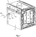
- FIG. 1 is a perspective view of a household appliance in the form of a steamer according to a first embodiment of the present invention is shown in a simplified schematic representation.
- the steam cooking appliance has a cooking chamber (not shown) located behind a door 6, into which the food to be cooked can be placed.
- a food placed in the cooking chamber is cooked during operation of the steam cooking appliance by water vapor introduced into the cooking chamber.
- the water vapor is generated by an evaporator unit (not shown).
- the steam cooking appliance has a control panel 4 which is attached to a panel support 2 and is arranged above the door 6 .
- a water tank 20 can be inserted into a receiving unit 60 for coupling to the evaporator unit.
- the water tank 20 has a base body 22 which is closed by a closure element 30 in the state shown.
- the base body 22 has an elongated circular-cylindrical shape.
- An outlet opening 29 is formed on an end section of the base body 22 that faces the steamer.
- the water tank 20 can be non-destructively and reversibly inserted into and removed from the receiving unit 60 in the actuation direction BR in order to reach an operating position.
- the liquid medium provided for evaporation in the form of water is stored in the water tank 20 .
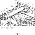
- FIG. 2 shows a perspective view showing a detail of the steamer from 1 shows schematically without an upper housing part of the steamer.
- a two-part receiving unit 60 of a water supply unit 10 is attached to the back of the panel support 2 in a recess formed in the panel support 2 . It is easy to see that connecting the receiving unit 60 to the panel support 2 corresponds to connecting a toggle socket 110 , which is why only one type of recess for the receiving unit 60 and the toggle socket 110 is provided in the shutter support 2 .
- the receiving unit 60 is formed from an upper housing part 62 and a lower housing part 64 .
- the receiving unit 60 has a bearing section (66 in FIG. 3 ) which is open in a direction away from the panel support 2 .
- a connector 79 which forms part of an arrangement for coupling the water tank (not shown) to the evaporator unit (not shown).
- a securing spring 68 is fastened to the opening 67, on which the connecting part 79 is supported via a compression spring (not shown).
- a microswitch 100 is provided in the area of the bearing section 66 on a mounting section 102 attached to the housing outer wall of the receiving unit 60 in order to detect an operating position of the water tank.
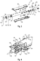
- the closure element 30 comprises a closure cover 32 and a covering cap 34 attached to the front.
- the closure cover 32 can be fastened to the base body 22 by means of a bayonet catch.
- a plurality of markings M are located on the base body 22 and can be used to read off the amount of water when the water tank 20 is being filled.
- An outlet opening 29 in which the valve unit 50 is arranged, is formed on the base body 22 of the water tank 20 on an end section opposite the closure element 30 .
- the valve unit 50 is designed as a pop-up valve.
- the adapter part 70 is formed from a securing part 78, a connecting part 79 and a sealing part 77 arranged between them.
- the securing part 78 On its section facing the water tank 20 , the securing part 78 has two latching elements in the form of latching tabs as the first connecting means, which can be brought into engagement with corresponding latching elements of the water tank 20 or the base body 22 .
- corresponding connecting elements are provided on the connecting part 79 on a first section facing the securing part 78 .
- a connecting piece is formed as a second connection means for coupling to the evaporator unit.
- a compression spring 76 supported on a securing spring 68 is provided in order to apply a spring force to the adapter part 70 in the direction of the water tank 20 .
- a link in the form of a heart curve is formed on a section of the connecting part 79, in which a link block 82 can be brought into engagement.
- the sliding block 82 is guided in a retaining clip 80.
- FIG. 4 shows a perspective view showing part of the 3 components shown schematically represents in an assembled state. Out of 4 the adapter part 70 formed by the securing part 78 and the connecting part 79 is clearly visible. Furthermore, it can be seen that a longitudinal slot 84 is formed on the retaining clip 80, in which the sliding block 82 is guided. 4 shows the operating state in which the water tank 20 is fully latched in its end position with the securing part 78 and the water stored in the tank can thus be supplied to the evaporator unit in a flow direction FR through the open push-open valve.
- a latching hook 78a formed on the securing part 78 engages with a latching projection formed on the base body 22 of the water tank 20, so that the water tank 20 is held stably in its operating position in combination with the spring force generated on the water tank 20 by the compression spring 76 becomes.
- FIG 5 shows a schematic exploded view of a closure element of a steamer according to a second embodiment of the present invention.
- the closure element 30 is formed from a closure cover 32, a cover cap 34 attached to the front of the closure cover 32, a seal carrier 48 with an O-ring 44 mounted thereon, and a spring 46 arranged between the seal carrier 48 and the closure cover 32.
- the O-ring 44 is attached to the circumference of the seal carrier 48 on an end section facing away from the closure cover 32 .
- the seal carrier 48 has a plurality of latching elements on the section facing the closure cover 32, with which the seal carrier 48 is fastened to the closure cover 32, with the spring 46 lying between them.
- the spring 46 is designed as a compression spring, so that on the one hand it is supported on the closure cover 32 and on the other hand it applies a spring force to the seal carrier 48 .
- FIG. 6 a schematic sectional view along the section plane IV-IV figure 5 , wherein the closure element is mounted on a main body of the water tank.
- the 0-ring seal 44 is pressed against the sealing edge 23 formed on the base body 22 by the spring force generated by the spring 46.
- the sealing edge 23 is formed in the interior of the base body 22 on the peripheral side.
- the base body 22 of the water tank 20 has a diameter at its end section facing the closure element 30 which is smaller than the diameter outside of the end section.
- the outer diameter of the closure element 30 essentially corresponds to the outer diameter of the base body 22 of the water tank 20.
- the inner diameter of the closure element 30 essentially corresponds to the outer diameter of the end section of the base body 22 facing the closure element 30.
Description
Die Erfindung betrifft ein Dampfgargerät mit einer Wasserversorgungseinheit, die einen entnahmbaren Wassertank aufweist, der in Einbaulage eine einem Benutzer zugewandte Vorderseite und eine der Vorderseite gegenüberliegende Rückseite und ein Verschlusselement zum Verschließen seiner Befüllöffnung aufweist, und einer mit der Wasserversorgungseinheit verbindbaren Verdampfereinheit, mit welcher Wasser der Wasserversorgungseinheit verdampfbar ist und der in der Verdampfereinheit erzeugte Dampf in den Garraum des Dampfgargeräts bereitstellbar ist.The invention relates to a steam cooking appliance with a water supply unit, which has a removable water tank which, in the installed position, has a front side facing the user and a rear side opposite the front side and a closure element for closing its filling opening, and an evaporator unit that can be connected to the water supply unit, with which water Water supply unit can be evaporated and the steam generated in the evaporator unit can be provided in the cooking chamber of the steam cooking appliance.
Es sind Backöfen bekannt, die auch die Möglichkeit bieten, Gargut durch Dampferzeugung im Garraum zuzubereiten. Dabei werden während der Zubereitung Dampfstöße erzeugt, die in den Garraum geleitet werden bzw. erst darin erzeugt werden. Dazu ist ein Behälter zur Bevorratung von Wasser erforderlich. Dieser kann bei bekannten Geräten im Bereich der Bedienblende des Backofens angeordnet sein und daraus entnommen werden. Dabei kann bei herkömmlichen Ausgestaltungen die Entnahme relativ aufwändig und unhandlich sein. Weiterhin gestaltet sich oftmals die Befüllung des Wassertanks schwierig.Ovens are known which also offer the possibility of preparing food to be cooked by generating steam in the cooking chamber. During preparation, bursts of steam are generated that are directed into the cooking compartment or are only generated there. This requires a container for storing water. In known devices, this can be arranged in the area of the control panel of the oven and can be removed therefrom. With conventional configurations, removal can be relatively complex and unwieldy. Furthermore, filling the water tank is often difficult.
Die
Die Beschreibung des Standes der Technik ist vorgesehen, um das Verständnis des Hintergrundes der vorliegenden Erfindung zu fördern, und kann Gegenstände außerhalb des Standes der Technik umfassen, der einem Durchschnittsfachmann bekannt ist.The description of prior art is provided to enhance understanding of the background of the present invention and may include subject matter outside the prior art that is known to a person of ordinary skill in the art.
Es ist eine Aufgabe der vorliegenden Erfindung, ein gegenüber dem Stand der Technik verbessertes Dampfgargerät bereitzustellen, dass die oben beschriebenen Nachteile beseitigt, während die aus dem Stand der Technik erzielten Vorteile beibehalten werden.It is an object of the present invention to provide an improved steamer over the prior art that eliminates the disadvantages described above while retaining the advantages achieved by the prior art.
Die Lösung der gestellten Aufgabe gelingt durch ein Dampfgargerät mit den Merkmalen des Anspruchs 1. Erfindungsgemäß kann dies bei einem Dampfgargerät nach dem Oberbegriff des Anspruchs 1 dadurch erreicht werden, dass der Wassertank ein Verschlusselement zum Verschließen seiner Befüllöffnung zum Befüllen mit Wasser aufweist, wobei das Verschlusselement zumindest abschnittsweise die Vorderseite oder die Rückseite des Wassertanks bildet. Unter einem Dampfgargerät soll jegliches Haushaltsgerät verstanden werden, welches in einen Garraum eingebrachtes Gargut mittels Wasserdampf gart und/oder ein Gargutergebnis verbessert. Es versteht sich, dass das Dampfgargerät sowohl ein Gargerät, beispielsweise ein Backofen, mit einer Dampffunktion, bei dem neben dem erzeugten Wasserdampf noch weitere Wärmequellen in Form von zum Beispiel Heizkörpern vorhanden sind, als auch ein Dampfgargerät, das ausschließlich Wasserdampf zum Erhitzen/Garen von Gargut verwendet, sein kann.The object set is achieved by a steam cooking appliance having the features of claim 1. According to the invention, this can be achieved in a steam cooking appliance according to the preamble of claim 1 in that the water tank has a closure element for closing its filling opening for filling with water, the closure element forms at least partially the front or the back of the water tank. A steam cooking appliance should be understood as meaning any household appliance which cooks food placed in a cooking chamber by means of steam and/or improves the result of the food to be cooked. It goes without saying that the steamer can be both a cooking device, for example an oven, with a steam function, in which there are other heat sources in the form of radiators, for example, in addition to the steam generated, and a steamer, which uses only steam for heating/cooking Food used can be.
Die Wasserversorgungseinheit kann neben dem oben erwähnten Wassertank auch weitere Komponenten aufweisen, die für die Versorgung einer Verdampfereinheit mit Wasser erforderlich sein können. Dazu zählen beispielsweise eine Wasserzuführungseinheit, die den Wassertank mit der Verdampfereinheit verbindet, sowie alle Arten von Leitungen und/oder Leitungssystemen sowie Anschluss- und/oder Verbindungselemente. Die Wasserzuführungseinheit weist an einem ersten Endabschnitt Mittel zur Kopplung mit dem Wassertank und an einem zweiten Endabschnitt Mittel zur Kopplung mit der Verdampfereinheit auf. Insbesondere ist die Wasserversorgungseinheit derart eingerichtet, dass sie einen Wasserkreislauf nach dem Prinzip der Vogeltränke ermöglicht. Dieses Vogeltränke-Prinzip ist dem Fachmann gut bekannt, weshalb eine ausführliche Beschreibung desselben weggelassen werden kann.In addition to the above-mentioned water tank, the water supply unit can also have other components that can be required for supplying an evaporator unit with water. These include, for example, a water supply unit that connects the water tank to the evaporator unit, as well as all types of lines and/or line systems and connecting and/or connecting elements. The water supply unit has means for coupling to the water tank on a first end section and means for coupling to the evaporator unit on a second end section. In particular, the water supply unit is set up in such a way that it has a water cycle based on the principle of the bird bath allows. This birdbath principle is well known to those skilled in the art, so a detailed description thereof can be omitted.
Unter Einbaulage des Wassertanks soll die Lage verstanden werden, in welcher der Wassertank in dem Dampfgargerät, beispielsweise in einer dafür vorgesehenen Halterung, aufgenommen und insbesondere betriebsbereit ist. Infolgedessen bildet die einem Benutzer zugewandte Vorderseite des Wassertanks einen sichtbaren Teil einer Bedienblende. Die Vorderseite ist an einem ersten Endabschnitt des Wassertanks gebildet und die Rückseite des Wassertanks ist an einem dem ersten Endabschnitt gegenüberliegenden Endabschnitt gebildet.The installation position of the water tank is to be understood as meaning the position in which the water tank is accommodated in the steamer, for example in a holder provided for this purpose, and in particular is ready for operation. As a result, the front of the water tank facing a user forms a visible part of a control panel. The front is formed at a first end portion of the water tank, and the rear of the water tank is formed at an end portion opposite to the first end portion.
Das in dem Wassertank bevorratete Wasser kann im Betrieb an eine im Dampfgargerät angeordnete Verdampfereinheit zugeführt werden. Mittels der Verdampfereinheit kann Dampf erzeugt und in den Garraum des Dampfgargeräts bereitgestellt werden. Die Funktion einer Verdampfereinheit ist dem Fachmann gut bekannt, weshalb eine ausführliche Beschreibung derselben weggelassen werden kann.During operation, the water stored in the water tank can be fed to an evaporator unit arranged in the steam cooking appliance. Steam can be generated by means of the evaporator unit and made available in the cooking chamber of the steam cooking appliance. The function of an evaporator unit is well known to those skilled in the art, so a detailed description thereof can be omitted.
Das Verschlusselement verschließt eine Befüllöffnung des Wassertanks zum Befüllen mit Wasser, insbesondere durch einen Wasserhahn, und insbesondere derart, dass bei Einbaulage des Wassertanks kein Wasser mehr austreten kann. Dadurch, dass das Verschlusselement zumindest abschnittsweise die Vorderseite oder die Rückseite des Wassertanks bildet, lässt sich ein positives Erscheinungsbild des Dampfgargeräts realisieren, da sich die jeweilige Seite des Wassertanks vorteilhaft in das Design des Geräts integrieren lässt, ohne Einbußen bezüglich des Benutzerkomforts beim Entnehmen/Befüllen des Wassertanks hinnehmen zu müssen. Das heißt, aus Designsicht ist nahezu die vollständige Integration der Wasserversorgungseinheit beziehungsweise des Wassertanks in einen Blendenträger bzw. eine Bedienblende des Dampfgargeräts möglich.The closure element closes a filling opening of the water tank for filling with water, in particular through a water tap, and in particular in such a way that no more water can escape when the water tank is in the installed position. Because the closure element forms the front or the back of the water tank, at least in sections, a positive appearance of the steamer can be achieved, since the respective side of the water tank can be advantageously integrated into the design of the device without sacrificing user comfort when removing/filling of the water tank to have to accept. From a design point of view, this means that the water supply unit or the water tank can be almost completely integrated into a panel support or a control panel of the steamer.
Aus Designsicht und aus Gründen der Reinigung ist es dabei besonders wünschenswert, dass die Vorderseite oder die Rückseite des Wassertanks mit der Frontfläche der Bedienblende im Wesentlichen bündig ist. Das heißt, die Vorder- oder Rückseite des Wassertanks ist in Einbaulage desselben derart in die Bedienblende integriert, dass keine störenden Komponenten vorhanden sind, welche in Bezug auf eine Frontfläche der Bedienblende in Richtung eines Benutzers hervorragen oder zurückversetzt angeordnet sind. Dadurch lässt sich in vorteilhafter Weise ein homogenes Erscheinungsbild realisieren. Das Verschlusselement beziehungsweise die Vorderseite des Verschlusselements ist grifflos und ist insbesondere eben ausgebildet, so dass sich eine gute Integration in die Bedienblende realisieren lässt.From a design point of view and for reasons of cleaning, it is particularly desirable that the front or the back of the water tank is essentially flush with the front surface of the control panel. This means that the front or back of the water tank is integrated into the control panel in the installation position of the same in such a way that no disruptive components are present which are related to a Protrude front surface of the control panel in the direction of a user or are set back. As a result, a homogeneous appearance can be realized in an advantageous manner. The closure element or the front side of the closure element has no handle and is in particular of planar design, so that good integration into the control panel can be implemented.
Erfindungsgemäß ist es vorgesehen, dass das Verschlusselement zumindest abschnittsweise die Vorderseite oder die Rückseite des Wassertanks bildet. Darunter soll verstanden werden, dass die einem Benutzer des Dampfgargeräts zugewandte Frontfläche des Verschlusselements zumindest einen Teil der Vorder- oder Rückseite bildet. Somit wäre es auch denkbar, dass die Frontfläche des Verschlusselements ein Flächenmaß aufweist, das kleiner als das Flächenmaß der Querschnittsfläche des Wassertanks ist, wobei die Frontfläche und die Querschnittsfläche im Wesentlichen parallel zueinander sind. Es ist jedoch ebenso vorstellbar, dass die Frontfläche ein Flächenmaß aufweist, das größer als das der Querschnittsfläche ist. Dies könnte insbesondere dann vorteilhaft sein, wenn ein Durchmesser des Wassertanks beziehungsweise dessen Querschnittsfläche kleiner als der Durchmesser beziehungsweise die Querschnittsfläche des in die Bedienblende des Dampfgargeräts zu integrierenden Verschlusselements ist. Somit ließe sich ein Wassertank in die Bedienblende integrieren, dessen Verschlusselement beispielsweise die gleiche Optik und/oder Größe und/oder Form wie ein daneben angeordneter Bedienknebel des Dampfgargeräts aufweist.According to the invention, it is provided that the closure element forms the front or the rear of the water tank, at least in sections. This is to be understood to mean that the front surface of the closure element facing a user of the steam cooking appliance forms at least part of the front or rear side. It would thus also be conceivable for the front surface of the closure element to have a surface area that is smaller than the surface area of the cross-sectional area of the water tank, with the front surface and the cross-sectional area being essentially parallel to one another. However, it is also conceivable that the front surface has a surface area that is larger than that of the cross-sectional surface. This could be particularly advantageous if a diameter of the water tank or its cross-sectional area is smaller than the diameter or the cross-sectional area of the closure element to be integrated into the control panel of the steamer. A water tank could thus be integrated into the control panel, the closure element of which has, for example, the same appearance and/or size and/or shape as a control knob of the steam cooking appliance arranged next to it.
Erfindungsgemäß ist es vorgesehen, dass das Verschlusselement die Vorderseite oder die Rückseite des Wassertanks bilden kann. Bildet das Verschlusselement zumindest abschnittsweise die Vorderseite des Wassertanks, dann ist die Frontfläche des Verschlusselements in Einbaulage des Wassertanks dem Benutzer zugewandt. Im Gegensatz dazu, wenn das Verschlusselement zumindest abschnittsweise die Rückseite des Wassertanks bildet, ist die Frontfläche des Verschlusselements dem Benutzer abgewandt und somit für den Benutzer nicht sichtbar. Somit würde der vor dem Dampfgargerät stehende Benutzer lediglich den Boden bzw. Bodenbereich sehen können, wohingegen die durch das Verschlusselement gebildete Rückseite des Wassertanks im Gerät verdeckt liegt. Es versteht sich für den Durchschnittsfachmann, dass im letzteren Fall in dem Verschlusselement Mittel/Komponenten vorgesehen sein können, die zum Verbinden/Koppeln mit der Wasserversorgungseinheit eingerichtet sind. Somit besteht der Unterschied zwischen den beiden beschriebenen Varianten lediglich darin, dass die Anbringung des Verschlusselements seitenvertauscht ist. Die Befüllöffnung des Wassertanks befindet sich insbesondere auf der gegenüberliegenden Seite einer Auslassöffnung desselben.According to the invention it is provided that the closure element can form the front or the back of the water tank. If the closure element forms the front of the water tank at least in sections, then the front surface of the closure element faces the user when the water tank is in the installed position. In contrast to this, when the closure element forms the back of the water tank at least in sections, the front surface of the closure element faces away from the user and is therefore not visible to the user. Thus, the user standing in front of the steam cooking appliance would only be able to see the floor or floor area, whereas the rear side of the water tank formed by the closure element is covered in the appliance. It will be understood by a person skilled in the art that in the latter case means/components are provided in the closure element set up to connect/couple to the water supply unit. Thus, the only difference between the two variants described is that the attachment of the closure element is reversed. The filling opening of the water tank is located in particular on the opposite side of an outlet opening of the same.
Vorteilhafte Aus- und Weiterbildungen, die einzeln oder in Kombination miteinander eingesetzt werden können, sind Gegenstand der abhängigen Ansprüche.Advantageous training and developments that can be used individually or in combination with one another are the subject matter of the dependent claims.
Gemäß einer Ausführungsform der Erfindung ist das Verschlusselement durch einen Bajonett- oder Schraubverschluss an einem Grundkörper des Wassertanks befestigbar. Dadurch lässt sich der Wassertank komfortabel und schnell verschließen.According to one embodiment of the invention, the closure element can be fastened to a base body of the water tank by a bayonet connection or screw connection. This allows the water tank to be closed quickly and easily.
Vorzugsweise weist ein Grundkörper des Wassertanks eine im Wesentlichen längliche, vorzugsweise zylindrische, weiter vorzugsweise kreiszylindrische, Bauform auf, weshalb das eingefüllte Wasser in diesem (Haupt-)Teil des Wassertanks bevorratet ist. Dies hätte den Vorteil, dass sich einerseits in Bezug auf neben dem Wassertank in/an der Bedienblende des Dampfgargeräts angeordnete Bedienknebel ein verbessertes optische Ergebnis als auch eine verbesserte Handhabung beim Befüllen des Wassertanks erzielen ließe. Das heißt, der vor dem Dampfgargerät stehende Benutzer würde zu dem Eindruck gelangen können, dass es sich bei dem eingeschobenen Wassertank, also in Einbaulage, optisch um einen Bedienknebel handelt. Es ist weiterhin bevorzugt, dass an dem im Wesentlichen transparenten Grundkörper des Wassertanks Markierungen über den Füllstand vorgesehen sind. Der Grundkörper kann in nicht einschränkender Weise aus Kunststoff hergestellt sein. Es versteht sich, dass der gesamte Wassertank aus Kunststoff hergestellt sein kann. Es ist jedoch auch vorstellbar, dass das Verschlusselement ein anderes Material als das des Grundkörpers aufweist. Das Verschlusselement ist an einem ersten Endabschnitt des Grundkörpers, beispielsweise durch eines der oben erwähnten Verschlussarten, anbringbar, wobei der Grundkörper an dem ersten Endabschnitt eine der Verschlussart entsprechende Ausgestaltung, beispielsweise ein Gewinde, Teil eines Bajonettverschlusses oder dergleichen, aufweist. An dem zweiten Endabschnitt des Grundkörpers, der dem ersten Endabschnitt gegenüberliegt, ist eine Auslassöffnung vorgesehen, in der eine Ventileinheit angebracht ist, die später beschrieben wird.A base body of the water tank preferably has an essentially elongated, preferably cylindrical, more preferably circular-cylindrical design, which is why the filled water is stored in this (main) part of the water tank. This would have the advantage that, on the one hand, with regard to the control knobs arranged next to the water tank in/on the control panel of the steamer, an improved visual result as well as improved handling when filling the water tank could be achieved. This means that the user standing in front of the steam cooking appliance would be able to get the impression that the inserted water tank, ie in the installed position, is optically a control knob. It is also preferred that markings about the fill level are provided on the essentially transparent base body of the water tank. The body may be made of plastic, without limitation. It goes without saying that the entire water tank can be made of plastic. However, it is also conceivable that the closure element has a different material than that of the base body. The closure element can be attached to a first end section of the base body, for example using one of the above-mentioned types of closure, the base body having a configuration corresponding to the type of closure on the first end section, for example a thread, part of a bayonet closure or the like. At the second end portion of the main body, which is opposite to the first end portion, there is provided an outlet port in which a valve unit, which will be described later, is mounted.
Zur besseren Abdichtung kann das Verschlusselement und/oder der Grundkörper an einem Verbindungsabschnitt eine Dichtung, insbesondere eine Gummidichtung, aufweisen. Dadurch kann eine verbesserte Dichtwirkung erzielt werden. Es kann beispielsweise vorgesehen sein, dass die Dichtung einen Außendurchmesser aufweist, der im Wesentlichen einem Innendurchmesser des Verschlusselements entspricht. Die Dichtung liegt dabei im Schließzustand des Verschlusselements im Wesentlichen an einem stirnseitigen Frontabschnitt des Grundkörpers oder seiner Außenmantelfläche an. Die Dichtung kann lose in das Verschlusselement eingelegt werden oder fest mit diesem verbunden sein. Bei einer einstückigen/integralen Ausbildung des Verschlusselements und der Dichtung könnte ein Verlust der losen Dichtung verhindert werden.For better sealing, the closure element and/or the base body can have a seal, in particular a rubber seal, on a connecting section. As a result, an improved sealing effect can be achieved. Provision can be made, for example, for the seal to have an outside diameter which essentially corresponds to an inside diameter of the closure element. When the closure element is in the closed state, the seal essentially rests against a front section of the base body or its outer lateral surface. The seal can be placed loosely in the closure element or be firmly connected to it. With a one-piece/integral design of the closure element and the seal, loss of the loose seal could be prevented.
Vorzugsweise ist die Gummidichtung als 0-Ring ausgebildet, der in einer Schließstellung des Verschlusselements durch eine Feder gegen eine Dichtkante des Grundkörpers gedrückt ist. Somit kann eine nochmals verbesserte Dichtwirkung erzielt werden. Als Feder können in der gesamten Offenbarung in nicht einschränkender Weise jede Art von Feder, wie beispielsweise eine Schraubenfeder, Spiralfeder oder dergleichen, verwendet werden. Besonders bevorzugt ist es, dass der 0-Ring auf einem Dichtungsträger, insbesondere topfförmigen Dichtungsträger, angeordnet ist und dass die Feder zwischen einem Verschlussdeckel des Verschlusselements und dem Dichtungsträger angeordnet ist. Diese Anordnung weist den Vorteil auf, dass die Dichtung in Form des 0-Rings federkraftbeaufschlagt gegen die am Grundkörper gebildete Dichtkante gedrückt wird, weshalb die Dichtwirkung nochmals verstärkt wird. Darüber hinaus ist es vorgesehen, dass der Dichtungsträger derart ausgeführt ist, dass er, beispielsweise mittels einer Verrastung, an dem Verschlussdeckel angebracht ist. Hierdurch ließe sich ein Verschlusselement in Form einer kompakten Baueinheit herstellen, die den Verschlussdeckel, die Dichtung, den Dichtungsträger und die zwischen Dichtungsträger und Verschlussdeckel angeordnete Feder aufweist. in diesem Zusammenhang ist an dem Dichtungsträger eine umfangsseitige Nut/Vertiefung vorgesehen, an/in die der O-Ring anbringbar ist. Die Nut ist insbesondere an einem dem Grundkörper des Wassertanks zugewandten Endabschnitt angeordnet.The rubber seal is preferably designed as an O-ring, which is pressed against a sealing edge of the base body by a spring when the closure element is in a closed position. A further improved sealing effect can thus be achieved. Any type of spring, such as a coil spring, coil spring, or the like, may be used as the spring throughout the disclosure without limitation. It is particularly preferred that the 0-ring is arranged on a seal carrier, in particular a cup-shaped seal carrier, and that the spring is arranged between a closure cover of the closure element and the seal carrier. This arrangement has the advantage that the seal in the form of the 0-ring is pressed by spring force against the sealing edge formed on the base body, for which reason the sealing effect is further reinforced. In addition, it is provided that the seal carrier is designed in such a way that it is attached to the closure cover, for example by means of a latch. As a result, a closure element could be produced in the form of a compact structural unit which has the closure cover, the seal, the seal carrier and the spring arranged between the seal carrier and the closure cover. in this context, a peripheral groove/recess is provided on the seal carrier, to/into which the O-ring can be attached. The groove is arranged in particular on an end section facing the base body of the water tank.
In einer weiteren Ausführungsform ist vorgesehen, dass das Verschlusselement eine Abdeckkappe aufweist, die zumindest abschnittsweise die Vorderseite des Wassertanks bildet. Hiermit kann eine spezielle Anpassung an das vorhandene Design des Dampfgargeräts erzielt werden. Dies betrifft insbesondere die Fälle, in denen verschiedene Blendenmaterialen, wie beispielsweise Glas, Metall oder dergleichen, verwendet werden. Darüber hinaus ist es durch eine in das Erscheinungsbild des Dampfgargeräts integrierte Abdeckkappe möglich, verschiedene Designlinien eines Hausgeräte-Herstellers abzudecken. Dabei ist es besonders bevorzugt, wenn das Verschlusselement beziehungsweise der Verschlussdeckel eine Schnittstelle/Anbindung aufweist, die der Schnittstelle/Anbindung des Bedienknebels entspricht. Im Falle der Anbringung der Abdeckkappe ist es ebenfalls vorgesehen, dass die Vorderseite des Wassertanks mit der Frontfläche der Bedienblende bündig ist.In a further embodiment it is provided that the closure element has a covering cap which at least partially forms the front side of the water tank. This allows a special adaptation to the existing design of the steamer can be achieved. This applies in particular to cases in which different screen materials, such as glass, metal or the like, are used. In addition, it is possible to cover different design lines of a household appliance manufacturer by means of a covering cap integrated into the appearance of the steamer. It is particularly preferred if the closure element or the closure cover has an interface/connection that corresponds to the interface/connection of the control knob. If the cover cap is attached, it is also provided that the front side of the water tank is flush with the front surface of the control panel.
Zur fluidtechnischen Kopplung mit der Verdampfereinheit weist der Wassertank zur Kopplung eine Ventileinheit auf. Diese Ventileinheit dient der fluidtechnischen Kopplung uns ist zum Befüllen mit Wasser geeignet. Die Kopplung erfolgt in der Regel mittels einer nach dem Vogeltränke-Prinzip arbeitenden Wasserzuführungseinheit, welche das Verbindungsglied zwischen dem Wassertank und der Verdampfereinheit darstellt. Die Ventileinheit weist in nicht einschränkender Weise ein Ventil beziehungsweise eine Ventilvorrichtung in Form eines Aufstoß-Ventils auf, das das im Wassertank bevorratete Wasser in Richtung der Verdampfereinheit ablaufen lässt, sobald die Ventileinheit mit einem Anschlusselement oder Andockstutzen einer Wasserzuführungseinheit gekoppelt oder verbunden ist. Die Ventileinheit ist in/an einer in dem Grundkörper des Wassertanks gebildeten Auslassöffnung vorgesehen. Die Wasserzuführungseinheit weist dabei in nicht einschränkender Weise ein Leitungssystem zum Zuführen des Wassers zu der Verdampfereinheit auf, wobei das Anschlusselement oder der Andockstutzen dann an dem Leitungssystem vorgesehen ist. Das Leitungssystem arbeitet wie eingangs erwähnt nach dem Vorgeltränke-Prinzip. Dabei öffnet sich die Ventileinheit erst im vollständig eingeschobenen Zustand des Wassertanks.For fluidic coupling to the evaporator unit, the water tank has a valve unit for coupling. This valve unit is used for fluid-technical coupling and is suitable for filling with water. The coupling usually takes place by means of a water supply unit that works according to the bird bath principle and represents the link between the water tank and the evaporator unit. The valve unit has, in a non-limiting manner, a valve or a valve device in the form of a pop-up valve, which allows the water stored in the water tank to drain in the direction of the evaporator unit as soon as the valve unit is coupled or connected to a connecting element or docking socket of a water supply unit. The valve unit is provided in/at an outlet port formed in the main body of the water tank. In this case, the water supply unit has, in a non-limiting manner, a line system for supplying the water to the evaporator unit, the connection element or the docking connector then being provided on the line system. As mentioned at the beginning, the pipe system works according to the pre-gel drinking principle. The valve unit only opens when the water tank is fully pushed in.
In einer weiteren Ausführungsform der vorliegenden Erfindung ist vorgesehen, dass die Wasserversorgungseinheit eine Aufnahmeeinheit zur Aufnahme des Wassertanks aufweist, wobei die Aufnahmeeinheit insbesondere an einem Blendenträger des Dampfgargeräts angebracht ist. Die Aufnahmeeinheit weist bevorzugt eine untere und eine obere Gehäuseschale auf und ist bevorzugt aus einem Kunststoff hergestellt. Es ist besonders vorteilhaft, wenn die Aufnahmeeinheit eine Schnittstelle/Anbindung aufweist, die der Schnittstelle/Anbindung eines ebenfalls an dem Blendenträger angeordneten Knebeltopfes entspricht. Dadurch wären Vorteile sowohl bei der Herstellung als auch bei der Montage erzielbar, da in dem Blendenträger für die Aufnahmeeinheit keine unterschiedlichen Öffnungen/Durchbrüche hergestellt werden müssen. Vorzugsweise kann, insbesondere an einer Außenseite der Aufnahmeeinheit, ein Mikroschalter angeordnet sein, durch welchen erfasst werden kann, ob der Wassertank vollständig gekoppelt ist. Beispielsweise könnte bei einer fehlerhaften, also unvollständigen Kopplung des Wassertanks durch den Mikroschalter an eine Steuerung des Dampfgargeräts ein Signal über die fehlerhafte Kopplung ausgegeben werden, so dass wiederum eine entsprechende Nachricht an einen Benutzer ausgegeben werden könnte.In a further embodiment of the present invention, it is provided that the water supply unit has a receiving unit for receiving the water tank, the receiving unit being attached in particular to a panel support of the steam cooking appliance. The receiving unit preferably has a lower and an upper housing shell and is preferably made of a plastic. It is particularly advantageous if the receiving unit has an interface/connection which is also connected to the interface/connection on the panel support arranged toggle pot corresponds. As a result, advantages could be achieved both during manufacture and during assembly, since no different openings/perforations need to be made in the screen support for the receiving unit. A microswitch can preferably be arranged, in particular on an outside of the receiving unit, by means of which it can be detected whether the water tank is fully coupled. For example, if the water tank is incorrectly, ie incompletely, coupled by the microswitch to a controller of the steamer, a signal about the incorrect coupling could be output, so that in turn a corresponding message could be output to a user.
Zur besseren Anpassung an den Wassertank kann es bevorzugt sein, dass die Aufnahmeeinheit eine im Wesentlichen längliche, vorzugsweise zylindrische, weiter vorzugsweise kreiszylindrische Bauform aufweist. Es versteht sich für einen Durchschnittsfachmann, dass im Falle einer durch eine obere und untere Gehäuseschale gebildeten Aufnahmeeinheit beide Gehäuseschalen beispielsweise jeweils die Form eines entsprechenden Halbzylinders aufweisen können. Darüber hinaus versteht es sich, dass sich die längliche, vorzugsweise zylindrische oder kreiszylindrische Bauform nicht über die gesamte Länge der Aufnahmeeinheit erstrecken muss, sondern lediglich ein bestimmter oder vorgegebener Abschnitt diese Form aufweist. Insbesondere weist dieser Abschnitt eine Länge auf, die 50%, bevorzugt 60% und weiter bevorzugt 70% der Gesamtlänge in Erstreckungsrichtung der Aufnahmeeinheit entspricht.For better adaptation to the water tank, it can be preferred that the receiving unit has a substantially elongate, preferably cylindrical, more preferably circular-cylindrical design. It is clear to a person skilled in the art that in the case of a receiving unit formed by an upper and lower housing shell, both housing shells can each have the shape of a corresponding semi-cylinder, for example. In addition, it goes without saying that the elongated, preferably cylindrical or circular-cylindrical shape does not have to extend over the entire length of the receiving unit, but rather only a specific or predetermined section has this shape. In particular, this section has a length that corresponds to 50%, preferably 60% and more preferably 70% of the total length in the direction of extension of the receiving unit.
Gemäß einer weiteren Ausführungsform der vorliegenden Erfindung weist die Aufnahmeeinheit ein Adapterteil mit einem ersten Anschlussmittel zum fluidtechnischen Verbinden, insbesondere durch Verrasten, des Wassertanks in einer Betriebsstellung einerseits und einem zweiten Anschlussmittel zum Koppeln mit der Verdampfereinheit andererseits auf. Dadurch kann eine einfache und sichere Kopplung zwischen dem Wassertank und der Verdampfereinheit sowie des Wassertanks in der Aufnahmeeinheit realisiert werden. Das erste Anschlussmittel kann dabei insbesondere durch eine Rastfeder oder ein Rastelement gebildet werden, dass mit einem am Grundkörper des Wassertanks gebildeten Rastabschnitt oder Rastvorsprung im vollständig eingeschobenen Zustand des Wassertanks verrastet wird. Das zweite Anschlussmittel kann insbesondere ein Andock- oder Anschlussstutzen sein, an welchem beispielsweise ein Schlauch oder eine Leitung einer Wasserzuführungseinheit zur Kopplung mit der Verdampfereinheit angebracht ist. Mittels einer an der Aufnahmeeinheit angebrachten Sicherungsfeder kann das Adapterteil an der Aufnahmeeinheit fixiert werden.According to a further embodiment of the present invention, the receiving unit has an adapter part with a first connection means for fluidically connecting, in particular by latching, the water tank in an operating position on the one hand and a second connection means for coupling to the evaporator unit on the other. As a result, a simple and secure coupling between the water tank and the evaporator unit and the water tank in the receiving unit can be implemented. The first connecting means can be formed in particular by a latching spring or a latching element that is latched with a latching section or latching projection formed on the base body of the water tank when the water tank is fully pushed in. The second connection means can in particular be a docking or connecting piece on which, for example a hose or pipe of a water supply unit is attached for coupling to the evaporator unit. The adapter part can be fixed to the receiving unit by means of a securing spring attached to the receiving unit.
Gemäß noch einer weiteren Ausführungsform weist das Adapterteil ein Sicherungsteil mit dem ersten Anschlussmittel und ein Verbindungsteil mit dem zweiten Anschlussmittel auf, wobei das Verbindungsteil und und das Sicherungsteil durch zwei separate Bauteile gebildet sein können. Durch diese zweiteilige Ausführung kann beispielsweise die Anordnung von zusätzlichen Komponenten, wie beispielsweise eine zwischen dem Sicherungsteil und dem Verbindungsteil angeordnete und austauschbare Dichtung/Gummidichtung, vorgesehen werden. Das Sicherungsteil kann beispielsweise an einem ersten Endabschnitt das erste Anschlussmittel in Form von Rastlaschen/Rasthaken oder dergleichen aufweisen und an dem zweiten Endabschnitt, der dem ersten Endabschnitt gegenüberliegt, ein Koppelelement zum KoppeinNerbinden mit dem Verbindungsteil in Form von Rastvorsprüngen, Rastlaschen oder dergleichen aufweisen. Das Verbindungsteil, das eingerichtet ist, um den Wassertank mit der Verdampfereinheit über eine Wasserzuführungseinheit zu koppeln, kann an einem ersten Endabschnitt das zweite Anschlusselement in Form eines Andockstutzens oder dergleichen aufweisen und an dem zweiten Endabschnitt, der dem ersten Endabschnitt gegenüberliegt, ebenfalls ein Koppelelement, das mit dem Koppelelement des Sicherungsteils in Eingriff gebracht werden kann oder mit diesem verrastbar ist, in Form von Rastvorsprüngen oder dergleichen aufweisen.According to yet another embodiment, the adapter part has a safety part with the first connection means and a connection part with the second connection means, it being possible for the connection part and the safety part to be formed by two separate components. This two-part design makes it possible, for example, to provide for the arrangement of additional components, such as a replaceable seal/rubber seal arranged between the securing part and the connecting part. The securing part can, for example, have the first connection means in the form of latching tabs/latching hooks or the like on a first end section and have a coupling element for coupling to the connecting part in the form of latching projections, latching tabs or the like on the second end section, which is opposite the first end section. The connecting part, which is set up to couple the water tank to the evaporator unit via a water supply unit, can have the second connection element in the form of a docking connector or the like on a first end section and also a coupling element on the second end section, which is opposite the first end section. which can be brought into engagement with the coupling element of the securing part or can be latched with it, in the form of latching projections or the like.
Vorzugsweise ist das Adapterteil in einem in der Aufnahmeeinheit gebildeten Lagerabschnitt im Wesentlichen in einer Betätigungsrichtung des Wassertanks verschiebbar gelagert, wodurch beispielsweise ein Mechanismus zum Ein- und Ausführen des Wassertanks realisiert werden kann. Das Ein- und Ausführen kann sowohl manuell als auch in Form eines Elektromotors vorgesehen werden. Im Falle des Elektromotors könnte dann beispielsweise eine Taste in der Bedienblende vorgesehen werden, um das Ein- und/oder Ausführen des Wassertanks zu starten. Die Betätigungsrichtung des Wassertanks entspricht der Richtung, in die der Wassertank in die Aufnahmeeinheit eingeführt und daraus entnommen werden kann.The adapter part is preferably mounted in a bearing section formed in the receiving unit so that it can be displaced essentially in an actuation direction of the water tank, as a result of which a mechanism for inserting and removing the water tank can be implemented, for example. The entry and exit can be provided both manually and in the form of an electric motor. In the case of the electric motor, a button could then be provided on the control panel, for example, in order to start loading and/or unloading the water tank. The operating direction of the water tank corresponds to the direction in which the water tank can be inserted into and removed from the receiving unit.
Es ist besonders bevorzugt, wenn das Adapterteil eine Kulisse aufweist und durch eine Feder im Wesentlichen in der Betätigungsrichtung federkraftbeaufschlagt ist, wobei in die Kulisse ein Kulissenstein eingreift, der in einer Halteklammer geführt ist. Dadurch kann in einfacher Weise eine Einheit/Anordnung zum Ein- und/oder Ausführen des Wassertanks realisiert werden. Es versteht sich für den Durchschnittsfachmann, dass die Kulisse ebenfalls in dem Sicherungsteil oder dem Verbindungsteil gebildet werden kann. Insbesondere ist eine sogenannte Herzkurve als Kulisse vorgesehen. Das Vorsehen einer Feder/Druckfeder, die das Adapterteil mit einer Federkraft beaufschlagt, weist den Vorteil auf, dass die Einheit/Anordnung und somit der Wassertank in fest definierte Positionen bringbar ist und sich keine Zwischenstellungen ergeben können. Die Feder kann sich gemäß einer Weiterbildung an einer Sicherungsfeder oder einem Sicherungsbügel abstützen, die bzw. der an der Aufnahmeeinheit, bevorzugt an der unteren Gehäuseschale, angeordnet ist. Der Kulissenstein wird vorzugsweise in einem Längsschlitz der Halteklammer geführt, die bevorzugt an der unteren Gehäuseschale angeordnet ist. Der Längsschlitz verläuft im Wesentlichen senkrecht zu einer Haupterstreckungsrichtung des Wassertanks beziehungsweise zu der zuvor erwähnten Betätigungsrichtung desselben.It is particularly preferred if the adapter part has a link and is subjected to spring force by a spring essentially in the direction of actuation, with a link block, which is guided in a retaining clip, engaging in the link. As a result, a unit/arrangement for inserting and/or removing the water tank can be implemented in a simple manner. It will be understood by those of ordinary skill in the art that the link can also be formed in the securing part or the connecting part. In particular, a so-called heart curve is provided as a backdrop. The provision of a spring/compression spring, which applies a spring force to the adapter part, has the advantage that the unit/arrangement and thus the water tank can be brought into firmly defined positions and no intermediate positions can arise. According to a further development, the spring can be supported on a securing spring or a securing clip which is arranged on the receiving unit, preferably on the lower housing shell. The sliding block is preferably guided in a longitudinal slot of the retaining clip, which is preferably arranged on the lower housing shell. The longitudinal slot runs essentially perpendicularly to a main extension direction of the water tank or to the previously mentioned direction of actuation of the same.
Gemäß einer Ausführungsform der Erfindung ist der Wassertank mittels einer Push-Push-Einheit aus dem Dampfgargerät entnehmbar ist. Es kann jedoch alternativ dazu auch jedes andere Prinzip verwendet werden, das zum Ein- und Ausführen des Wassertanks geeignet ist. Beispielsweise kann auch eine Entriegelungsmechanik vorgesehen sein, die beispielsweise durch eine an der Bedienblende angebrachte Entriegelungstaste betätigt wird. In diesem Fall würde eine Betätigung der Taste zu einem zumindest teilweisen Auswurf des Wassertanks führen. Die Verriegelung in der Aufnahmeeinheit könnte dann zum Beispiel durch Einführen und Verrasten desselben durch den Benutzer realisiert werden.According to one embodiment of the invention, the water tank can be removed from the steamer by means of a push-push unit. However, any other principle that is suitable for inserting and removing the water tank can also be used as an alternative to this. For example, an unlocking mechanism can also be provided, which is actuated, for example, by an unlocking button attached to the control panel. In this case, pressing the button would lead to at least partial ejection of the water tank. The locking in the receiving unit could then be implemented, for example, by the user inserting and latching the same.
Bei Verwenden einer Push-Push-Einheit kann es in uneingeschränkter Weise drei wesentliche Zustände geben. Erstens einen eingefahrenen Zustand, der einem Betriebszustand des Wassertanks entspricht, in welchem der Wassertank vollständig angedockt ist, so dass Wasser aus dem Wassertank in Richtung der Verdampfereinheit ausgetragen werden kann. In diesem Zustand ist die Vorderseite des Wassertanks im Wesentlichen bündig mit der Frontfläche der Bedienblende. Ein zweiter Zustand kann einem überdrückten Zustand nach Betätigung der Push-Push-Einheit entsprechen.Unrestrictedly, when using a push-push unit, there can be three main states. First, a retracted state, which corresponds to an operating state of the water tank, in which the water tank is fully docked, so that water can be discharged from the water tank in the direction of the evaporator unit. In this state, the front of the water tank is essentially flush with the front surface of the control panel. A second state can correspond to a depressed state after actuation of the push-push unit.
Hierbei wird auf die Vorderseite des Wassertanks gedrückt, bis der Wassertank eine Endposition aufgrund des in der Kulisse geführten Kulissensteines erreicht. In diesem überdrückten Zustand befindet sich die Vorderseite in Bezug auf die Frontfläche zurückversetzt. Der Versatz nach hinten, also in Einführrichtung des Wassertanks, kann beispielsweise ungefähr 3 mm betragen. Ein dritter Zustand kann einem ausgefahrenen Zustand des Wassertanks entsprechen. Der ausgefahrene Zustand wird erreicht nach Wegnehmen der durch das Drücken erzeugten Kraft auf die Vorderseite des Wassertanks, bis der Wassertank eine weitere Endposition aufgrund des in der Kulisse in Eingriff stehenden Kulissensteins erreicht. In diesem ausgefahren Zustand ragt die Vorderseite des Wassertanks in Bezug auf die Frontfläche der Bedienblende in Richtung eines Benutzers vor. Der entsprechende Versatz nach vorne kann ungefähr 18 mm betragen, so dass ein ausreichend großer Bereich zum Anfassen und Herausnehmen des Wassertanks vorhanden ist.In this case, the front of the water tank is pressed until the water tank reaches an end position due to the sliding block guided in the connecting link. In this depressed condition, the front is set back with respect to the front face. The offset to the rear, ie in the direction of insertion of the water tank, can be approximately 3 mm, for example. A third state can correspond to an extended state of the water tank. The extended state is reached after removing the force generated by the pressing on the front of the water tank until the water tank reaches a further end position due to the sliding block being engaged in the connecting link. In this extended state, the front of the water tank protrudes toward a user with respect to the front surface of the control panel. The corresponding forward offset can be approximately 18 mm, so that there is a sufficiently large area to grasp and remove the water tank.
Das erfindungsgemäße Dampfgargerät weist eine einfache Wasserversorgungseinheit mit einem leicht zu befüllenden Wassertank auf und ist somit weniger störungsanfällig als die aus dem Stand der Technik bekannten Geräte. Weiterhin wird durch die spezielle Ausgestaltung des vollständig entnehmbaren Wassertanks der Befüllvorgang vereinfacht, da der Wassertank mit Hilfe eines normalen Wasserhahns befüllt werden kann. Nach einem Befüllvorgang kann der Wassertank durch das Verschlusselement verschlossen werden und in die am Dampfgargerät vorgesehene Aufnahmeeinheit eingeführt werden. Hierbei ist es ebenfalls vorstellbar, dass an dem Wassertank und/oder der Aufnahmeeinheit eine Verdrehsicherung vorgesehen ist.The steam cooking appliance according to the invention has a simple water supply unit with an easy-to-fill water tank and is therefore less susceptible to faults than the appliances known from the prior art. Furthermore, the filling process is simplified by the special design of the completely removable water tank, since the water tank can be filled using a normal tap. After a filling process, the water tank can be closed by the closure element and inserted into the receiving unit provided on the steamer. It is also conceivable here for an anti-twist device to be provided on the water tank and/or the receiving unit.
Die obigen und weiteren Merkmale der vorliegenden Erfindung werden nun mit Bezug auf bestimmte Ausführungsbeispiele davon ausführlich beschrieben, welche durch die beigefügten Zeichnungen dargestellt sind, und welche im Folgenden nur zur Veranschaulichung dienen, und somit nicht für die vorliegende Erfindung einschränkend sind. in der Zeichnung zeigen:
- Fig. 1
- eine perspektivische Ansicht, die ein Haushaltsgerät in Form eines Dampfgargeräts gemäß einem ersten Ausführungsbeispiel der vorliegenden Erfindung schematisch darstellt;
- Fig. 2
- eine perspektivische Ansicht, die einen Ausschnitt des Dampfgargeräts von
Fig. 1 ohne ein oberes Gehäuseteil schematisch darstellt; - Fig. 3
- eine schematische Explosionsdarstellung von einzelnen Komponenten des Dampfgargeräts gemäß dem Ausführungsbeispiel der vorliegenden Erfindung;
- Fig. 4
- eine perspektivische Ansicht, die einen Teil der in
Fig. 3 dargestellten Komponenten in einem montierten Zustand schematisch darstellt; - Fig. 5
- eine schematische Explosionsdarstellung eines Verschlusselements eines Dampfgargeräts gemäß einem zweiten Ausführungsbeispiel der vorliegenden Erfindung;
- Fig. 6
- eine schematische Schnittdarstellung entlang der Schnittebene IV-IV aus
Fig. 5 , wobei das Verschlusselement an einem Grundkörper des Wassertanks montiert ist.
- 1
- a perspective view schematically showing a household appliance in the form of a steamer according to a first embodiment of the present invention;
- 2
- a perspective view showing a section of the steamer from
1 without an upper housing part; - 3
- a schematic exploded view of individual components of the steamer according to the embodiment of the present invention;
- 4
- a perspective view showing part of the in
3 schematically represents components shown in an assembled state; - figure 5
- a schematic exploded view of a closure element of a steamer according to a second embodiment of the present invention;
- 6
- a schematic sectional view along the section plane IV-IV
figure 5 , wherein the closure element is mounted on a main body of the water tank.
Es ist zu beachten, dass die beigefügten Zeichnungen nicht notwendigerweise maßstabgerecht sind und eine etwas vereinfachte Darstellung von verschiedenen bevorzugten Merkmalen darstellen, die der Veranschaulichung der Grundsätze der Erfindung dienen. Die spezifischen Konstruktionsmerkmale der vorliegenden Erfindung, wie sie hierin offenbart sind, einschließlich z.B. spezifischer Abmessungen, Orientierungen, Einbauorte und Formen werden zum Teil durch die eigens dafür vorgesehene Anmeldung und die Arbeitsumgebung bestimmt.It should be noted that the accompanying drawings are not necessarily to scale, presenting a somewhat simplified representation of various preferred features incorporated in the principles of the invention. The specific design features of the present invention as disclosed herein, including, for example, specific dimensions, orientations, locations, and shapes will be determined in part by the particular application and work environment.
In den Figuren werden gleiche oder funktionsgleiche Elemente mit den gleichen Bezugszeichen versehen.Elements that are the same or have the same function are provided with the same reference symbols in the figures.
Ausführungsbeispiele der vorliegenden Erfindung werden im Folgenden unter Bezugnahme auf die beigefügten Zeichnungen ausführlich beschrieben.Embodiments of the present invention are described in detail below with reference to the accompanying drawings.
In
Das Dampfgargerät weist eine an einem Blendenträger 2 angebrachte Bedienblende 4 auf, die oberhalb der Tür 6 angeordnet ist. In einem rechten Bereich der Bedienblende 4 kann ein Wassertank 20 in eine Aufnahmeeinheit 60 zur Kopplung mit der Verdampfereinheit eingeführt werden. Der Wassertank 20 weist einen Grundkörper 22 auf, der durch ein Verschlusselement 30 im gezeigten Zustand verschlossen ist. Der Grundkörper 22 weist eine länglich kreiszylindrische Form auf. An einem dem Dampfgargerät zugewandten Endabschnitt des Grundkörpers 22 ist eine Auslassöffnung 29 gebildet. Der Wassertank 20 kann in der Betätigungsrichtung BR in die Aufnahmeeinheit 60 zum Erreichen einer Betriebsstellung zerstörungsfrei und reversibel eingesetzt und entnommen werden. Das zur Verdampfung vorgesehene flüssige Medium in Form von Wasser ist in dem Wassertank 20 bevorratet.The steam cooking appliance has a control panel 4 which is attached to a panel support 2 and is arranged above the door 6 . In a right-hand area of the control panel 4, a water tank 20 can be inserted into a receiving unit 60 for coupling to the evaporator unit. The water tank 20 has a base body 22 which is closed by a closure element 30 in the state shown. The base body 22 has an elongated circular-cylindrical shape. An outlet opening 29 is formed on an end section of the base body 22 that faces the steamer. The water tank 20 can be non-destructively and reversibly inserted into and removed from the receiving unit 60 in the actuation direction BR in order to reach an operating position. The liquid medium provided for evaporation in the form of water is stored in the water tank 20 .
Die Aufnahmeeinheit 60 ist aus einem oberen Gehäuseteil 62 und einem unteren Gehäuseteil 64 gebildet. Im montierten Zustand, in dem das obere Gehäuseteil 62 und das untere Gehäuseteil 64 aneinander befestigt sind, weist die Aufnahmeeinheit 60 an einem hinteren Endbereich in Bezug auf den Blendenträger 2 einen Lagerabschnitt (66 in
An dem Grundkörper 22 befindet sich eine Mehrzahl von Markierungen M, mit denen die Wassermenge beim Befüllen des Wassertanks 20 abgelesen werden kann. An einem dem Verschlusselement 30 gegenüberliegenden Endabschnitt ist an dem Grundkörper 22 des Wassertanks 20 eine Auslassöffnung 29 gebildet, in der die Ventileinheit 50 angeordnet ist. Die Ventileinheit 50 ist als Aufstoßventil ausgeführt.A plurality of markings M are located on the base body 22 and can be used to read off the amount of water when the water tank 20 is being filled. An outlet opening 29 , in which the valve unit 50 is arranged, is formed on the base body 22 of the water tank 20 on an end section opposite the closure element 30 . The valve unit 50 is designed as a pop-up valve.
Wie aus
Im montierten Zustand ist eine an einer Sicherungsfeder 68 abgestützte Druckfeder 76 vorgesehen, um das Adapterteil 70 mit einer Federkraft in Richtung des Wassertanks 20 zu beaufschlagen. An einem Abschnitt des Verbindungsteils 79 ist eine Kulisse in Form einer Herzkurve gebildet, in der ein Kulissenstein 82 in Eingriff gebracht werden kann. Der Kulissenstein 82 wird in einer Halteklammer 80 geführt.In the assembled state, a compression spring 76 supported on a securing spring 68 is provided in order to apply a spring force to the adapter part 70 in the direction of the water tank 20 . A link in the form of a heart curve is formed on a section of the connecting part 79, in which a link block 82 can be brought into engagement. The sliding block 82 is guided in a retaining clip 80.
- 22
- Blendenträgervisor carrier
- 44
- Blendecover
- 66
- Türdoor
- 1010
- Wasserversorgungseinheitwater supply unit
- 2020
- Wassertankwater tank
- 2222
- Grundkörperbody
- 2323
- Dichtkantesealing edge
- 2424
- Vorderseitefront
- 2626
- Rückseiteback
- 2828
- Befüllöffnungfilling opening
- 2929
- Auslassöffnungexhaust port
- 3030
- Verschlusselementclosure element
- 3232
- Verschlussdeckelcap
- 3434
- Abdeckkappecover cap
- 4040
- Dichtungpoetry
- 4242
- Gummidichtungrubber seal
- 4444
- 0-Ring0 ring
- 4646
- FederFeather
- 4848
- Dichtungsträgerseal carrier
- 5050
- Ventileinheitvalve unit
- 6060
- Aufnahmeeinheitrecording unit
- 6262
- oberes Gehäuseteilupper housing part
- 6464
- unteres Gehäuseteillower housing part
- 6666
- Lagerabschnittstorage section
- 6767
- Öffnungopening
- 6868
- Sicherungsfedersafety spring
- 7070
- Adapterteiladapter part
- 7575
- Kulissebackdrop
- 7676
- Druckfedercompression spring
- 7777
- Dichtungsteilsealing part
- 7878
- Sicherungsteilfuse part
- 78a78a
- Rasthakenlatch hook
- 7979
- Verbindungsteilconnection part
- 8080
- Halteklammerretaining clip
- 8282
- Kulissensteinsliding block
- 8484
- Längsschlitzlongitudinal slit
- 9090
- Push-Puii-EinheitPush Puii unit
- 100100
- Mikroschaltermicro switch
- 102102
- Montageabschnittassembly section
- 110110
- Knebeltopftoggle pot
- BRBR
- Betätigungsrichtungoperating direction
- FRFR
- Flussrichtungflow direction
- MM
- Markierungmark
- VSvs
- Vorderseitefront
- RSRS
- Rückseiteback
Claims (15)
- Steam cooking appliance comprising a water supply unit (10) which has a removable water tank (20) which in the installed position has a front side (VS) facing a user and a rear side (RS) opposite the front side (VS), and an evaporator unit which can be connected to the water supply unit (10) and by means of which water from the water supply unit (10) can be evaporated and the steam generated in the evaporator unit can be provided into the cooking chamber of the steam cooking appliance, characterised in that the water tank has a closure element (30) for closing its filling opening (28), wherein the closure element (30) at least in part forms the front side (VS) or the rear side (RS) of the water tank (20).
- Steam cooking appliance according to claim 1, characterised in that the closure element (30) can be fastened or is fastened to a main body (22) of the water tank (20) by means of a bayonet or screw closure.
- Steam cooking appliance according to claim 1 or 2, characterised in that a main body (22) of the water tank (20) has an essentially elongated, preferably cylindrical, more preferably circular-cylindrical design.
- Steam cooking appliance according to one of the preceding claims, characterised in that the closure element (30) and/or the main body has a seal (40), in particular a rubber seal (42), on a connecting section.
- Steam cooking appliance according to claim 4, characterised in that the rubber seal (42) is designed as an O-ring (44) which, in a closed position of the closure element (30), is pressed by a spring (46) against a sealing edge (23) of the main body (22).
- Steam cooking appliance according to claim 5, characterised in that the O-ring (44) is arranged on a seal support (48), in particular a pot-shaped seal support, and in that the spring (46) is arranged between a closure cover (32) of the closure element (30) and the seal support (48).
- Steam cooking appliance according to one of the preceding claims, characterised in that the closure element (30) has a cover cap (34) which at least in part forms the front side (VS) of the water tank (20).
- Steam cooking appliance according to one of the preceding claims, characterised in that the water tank (20) has a valve unit (50) for coupling to the evaporator unit.
- Steam cooking appliance according to one of the preceding claims, characterised in that the water supply unit (10) has a receiving unit (60) for receiving the water tank (20), wherein the receiving unit is attached or arranged, in particular, to a panel support (2) of the steam cooking appliance.
- Steam cooking appliance according to claim 9, characterised in that the receiving unit (60) has an essentially elongated, preferably cylindrical, more preferably circular-cylindrical design.
- Steam cooking appliance according to claim 9 or 10, characterised in that the receiving unit (60) has an adapter part (70) with a first connecting means for fluidic coupling, in particular by latching, of the water tank (20) in an operating position on the one hand and a second connecting means for coupling to the evaporator unit on the other hand.
- Steam cooking appliance according to claim 11, characterised in that the adapter part (70) has a securing part (78) as a first connecting means and a connecting part (79) as a second connecting means.
- Steam cooking appliance according to claim 11 or 12, characterised in that the adapter part (70) is mounted so as to be displaceable in a bearing section (66) formed in the receiving unit (60) essentially in an actuating direction (BR) of the water tank (20).
- Steam cooking appliance according to claim 13, characterised in that the adapter part (70) has a slotted guide (75) and spring force is applied essentially in the actuating direction (BR) by a spring (76), wherein a sliding block (82), which is guided in a retaining clip (80), engages in the slotted guide (75).
- Steam cooking appliance according to one of the preceding claims, characterised in that the water tank (20) can be removed from the steam cooking appliance by means of a push-push unit (90).
Applications Claiming Priority (2)
| Application Number | Priority Date | Filing Date | Title |
|---|---|---|---|
| DE102017214928.0A DE102017214928A1 (en) | 2017-08-25 | 2017-08-25 | Steam cooker |
| PCT/EP2018/070109 WO2019038006A1 (en) | 2017-08-25 | 2018-07-25 | Steam cooking device |
Publications (2)
| Publication Number | Publication Date |
|---|---|
| EP3673210A1 EP3673210A1 (en) | 2020-07-01 |
| EP3673210B1 true EP3673210B1 (en) | 2022-10-26 |
Family
ID=63036054
Family Applications (1)
| Application Number | Title | Priority Date | Filing Date |
|---|---|---|---|
| EP18746161.1A Active EP3673210B1 (en) | 2017-08-25 | 2018-07-25 | Steam cooking device |
Country Status (7)
| Country | Link |
|---|---|
| US (1) | US20200182485A1 (en) |
| EP (1) | EP3673210B1 (en) |
| CN (1) | CN110945289B (en) |
| DE (1) | DE102017214928A1 (en) |
| ES (1) | ES2930024T3 (en) |
| PL (1) | PL3673210T3 (en) |
| WO (1) | WO2019038006A1 (en) |
Families Citing this family (10)
| Publication number | Priority date | Publication date | Assignee | Title |
|---|---|---|---|---|
| DE202018006413U1 (en) | 2017-08-09 | 2020-04-23 | Sharkninja Operating Llc | Cooking device and components thereof |
| US11033146B2 (en) | 2019-02-25 | 2021-06-15 | Sharkninja Operating Llc | Cooking device and components thereof |
| EP3931493A1 (en) | 2019-02-25 | 2022-01-05 | SharkNinja Operating LLC | Cooking system with guard |
| US11647861B2 (en) | 2020-03-30 | 2023-05-16 | Sharkninja Operating Llc | Cooking device and components thereof |
| US10973361B1 (en) | 2020-05-01 | 2021-04-13 | Wonderworx Llc | Cooking system for food steaming or cooking |
| DE102020207164A1 (en) * | 2020-06-08 | 2021-12-09 | BSH Hausgeräte GmbH | Steam cooker with specific receptacle for a water tank |
| DE102021201863A1 (en) | 2021-02-26 | 2022-09-01 | BSH Hausgeräte GmbH | Modular water tank for a steamer, and steamer and method |
| DE102021201956A1 (en) | 2021-03-01 | 2022-09-01 | BSH Hausgeräte GmbH | Evaporator for a household steamer and steamer drawer |
| DE102021202846A1 (en) | 2021-03-23 | 2022-09-29 | BSH Hausgeräte GmbH | Steam cooker with a specific fluid line system and method |
| EP4348117A1 (en) * | 2021-07-07 | 2024-04-10 | Gorenje d.o.o. | Household appliance with a liquid tank |
Family Cites Families (7)
| Publication number | Priority date | Publication date | Assignee | Title |
|---|---|---|---|---|
| FR2814734B1 (en) * | 2000-10-02 | 2003-01-17 | Brandt Cooking | REMOVABLE WATER TANK, ESPECIALLY FOR A STEAM COOKING OVEN |
| KR20050060560A (en) * | 2003-12-16 | 2005-06-22 | 삼성전자주식회사 | Heating cooker |
| ES2354468T3 (en) * | 2007-09-14 | 2011-03-15 | Teka Portugal, S.A. | VAPOR OVEN AND WATER TANK FOR USE IN THE SAME. |
| DE102010062888A1 (en) | 2010-12-13 | 2012-06-14 | BSH Bosch und Siemens Hausgeräte GmbH | Water tank for a Dampfgargerät, Dampfgargerät with such a water tank and method for removing a water tank from a recording in a Dampfgargerät |
| EP2550902B1 (en) * | 2011-07-27 | 2014-07-02 | Electrolux Home Products Corporation N.V. | Water drawer and appliance comprising water tank |
| JP6484801B2 (en) * | 2015-03-19 | 2019-03-20 | パナソニックIpマネジメント株式会社 | Cooker |
| CN205125911U (en) * | 2015-08-07 | 2016-04-06 | 宁波市安通机械有限公司 | Use food heating cabinet of steam |
-
2017
- 2017-08-25 DE DE102017214928.0A patent/DE102017214928A1/en active Pending
-
2018
- 2018-07-25 PL PL18746161.1T patent/PL3673210T3/en unknown
- 2018-07-25 ES ES18746161T patent/ES2930024T3/en active Active
- 2018-07-25 US US16/641,267 patent/US20200182485A1/en not_active Abandoned
- 2018-07-25 CN CN201880055255.4A patent/CN110945289B/en active Active
- 2018-07-25 EP EP18746161.1A patent/EP3673210B1/en active Active
- 2018-07-25 WO PCT/EP2018/070109 patent/WO2019038006A1/en unknown
Also Published As
| Publication number | Publication date |
|---|---|
| ES2930024T3 (en) | 2022-12-05 |
| PL3673210T3 (en) | 2023-01-16 |
| DE102017214928A1 (en) | 2019-02-28 |
| CN110945289A (en) | 2020-03-31 |
| CN110945289B (en) | 2022-06-24 |
| WO2019038006A1 (en) | 2019-02-28 |
| US20200182485A1 (en) | 2020-06-11 |
| EP3673210A1 (en) | 2020-07-01 |
Similar Documents
| Publication | Publication Date | Title |
|---|---|---|
| EP3673210B1 (en) | Steam cooking device | |
| EP2466214B1 (en) | Water tank for a steaming device and steaming device with such a water tank | |
| DE102007040310A1 (en) | Domestic appliance with a lockable by a door treatment room and with a filling device | |
| EP3180984B1 (en) | Cooking device | |
| DE10046347A1 (en) | Water feed for domestic electrical appliance e.g. washing machine or dishwasher, has separately controlled feed hoses for hot and cold water | |
| EP3673211B1 (en) | Steam cooking device | |
| EP2463590A2 (en) | Steam cooker with a water tank | |
| EP2463585A1 (en) | Water tank for a steaming device, steaming device with such a water tank and method for removing a water tank from a holder in a steaming device | |
| EP2990733A2 (en) | Cooking device | |
| DE4427460C2 (en) | Oven for steaming | |
| DE102017221534A1 (en) | Holding device for a heating device, as well as heating device with such a holding device | |
| EP3160660B1 (en) | Hand-held steam device | |
| DE102010027844A1 (en) | Tank for use in arrangement of household appliance, particularly steam cooker, has connection piece, which is formed for guiding medium in steam cooker for coupling with medium guiding unit of steam cooker | |
| EP2634492A1 (en) | Cooking device with filling opening for cleaning liquid, system comprising container and cooking device and method for filling a cooking device with cleaning liquid | |
| DE202012104006U1 (en) | Cooking appliance with filling opening for cleaning fluid and system consisting of container and cooking appliance | |
| DE202016104138U1 (en) | food processor | |
| EP3673209B1 (en) | Steam cooking device | |
| WO2016030239A1 (en) | Fluid connection device for a domestic appliance, and domestic appliance comprising such a fluid connection device | |
| DE3834352C1 (en) | ||
| DE102015107755B4 (en) | hose reel system | |
| DE4342453C2 (en) | Liquid draining device, in particular for draining fat from the fat pan of a deep fryer | |
| EP3716820A1 (en) | Device and method for preparing foods arranged in a vessel | |
| DE2711186B2 (en) | Rotary piston outlet valve, especially for a steam pressure boiler | |
| DE102021201865A1 (en) | Water-bearing household appliance and connection plug | |
| DE102013209113A1 (en) | Valve device, in particular for installation in a container lid |
Legal Events
| Date | Code | Title | Description |
|---|---|---|---|
| STAA | Information on the status of an ep patent application or granted ep patent |
Free format text: STATUS: UNKNOWN |
|
| STAA | Information on the status of an ep patent application or granted ep patent |
Free format text: STATUS: THE INTERNATIONAL PUBLICATION HAS BEEN MADE |
|
| PUAI | Public reference made under article 153(3) epc to a published international application that has entered the european phase |
Free format text: ORIGINAL CODE: 0009012 |
|
| STAA | Information on the status of an ep patent application or granted ep patent |
Free format text: STATUS: REQUEST FOR EXAMINATION WAS MADE |
|
| 17P | Request for examination filed |
Effective date: 20200325 |
|
| AK | Designated contracting states |
Kind code of ref document: A1 Designated state(s): AL AT BE BG CH CY CZ DE DK EE ES FI FR GB GR HR HU IE IS IT LI LT LU LV MC MK MT NL NO PL PT RO RS SE SI SK SM TR |
|
| AX | Request for extension of the european patent |
Extension state: BA ME |
|
| DAV | Request for validation of the european patent (deleted) | ||
| DAX | Request for extension of the european patent (deleted) | ||
| REG | Reference to a national code |
Ref country code: DE Ref legal event code: R079 Ref document number: 502018010923 Country of ref document: DE Free format text: PREVIOUS MAIN CLASS: F24C0015320000 Ipc: F24C0015000000 |
|
| RIC1 | Information provided on ipc code assigned before grant |
Ipc: F24C 15/32 20060101ALI20220223BHEP Ipc: F24C 15/00 20060101AFI20220223BHEP |
|
| GRAP | Despatch of communication of intention to grant a patent |
Free format text: ORIGINAL CODE: EPIDOSNIGR1 |
|
| STAA | Information on the status of an ep patent application or granted ep patent |
Free format text: STATUS: GRANT OF PATENT IS INTENDED |
|
| INTG | Intention to grant announced |
Effective date: 20220408 |
|
| GRAJ | Information related to disapproval of communication of intention to grant by the applicant or resumption of examination proceedings by the epo deleted |
Free format text: ORIGINAL CODE: EPIDOSDIGR1 |
|
| STAA | Information on the status of an ep patent application or granted ep patent |
Free format text: STATUS: REQUEST FOR EXAMINATION WAS MADE |
|
| GRAP | Despatch of communication of intention to grant a patent |
Free format text: ORIGINAL CODE: EPIDOSNIGR1 |
|
| STAA | Information on the status of an ep patent application or granted ep patent |
Free format text: STATUS: GRANT OF PATENT IS INTENDED |
|
| INTG | Intention to grant announced |
Effective date: 20220729 |
|
| GRAS | Grant fee paid |
Free format text: ORIGINAL CODE: EPIDOSNIGR3 |
|
| GRAA | (expected) grant |
Free format text: ORIGINAL CODE: 0009210 |
|
| STAA | Information on the status of an ep patent application or granted ep patent |
Free format text: STATUS: THE PATENT HAS BEEN GRANTED |
|
| AK | Designated contracting states |
Kind code of ref document: B1 Designated state(s): AL AT BE BG CH CY CZ DE DK EE ES FI FR GB GR HR HU IE IS IT LI LT LU LV MC MK MT NL NO PL PT RO RS SE SI SK SM TR |
|
| REG | Reference to a national code |
Ref country code: GB Ref legal event code: FG4D Free format text: NOT ENGLISH |
|
| REG | Reference to a national code |
Ref country code: CH Ref legal event code: EP |
|
| REG | Reference to a national code |
Ref country code: DE Ref legal event code: R096 Ref document number: 502018010923 Country of ref document: DE |
|
| REG | Reference to a national code |
Ref country code: AT Ref legal event code: REF Ref document number: 1527280 Country of ref document: AT Kind code of ref document: T Effective date: 20221115 |
|
| REG | Reference to a national code |
Ref country code: IE Ref legal event code: FG4D Free format text: LANGUAGE OF EP DOCUMENT: GERMAN |
|
| REG | Reference to a national code |
Ref country code: ES Ref legal event code: FG2A Ref document number: 2930024 Country of ref document: ES Kind code of ref document: T3 Effective date: 20221205 |
|
| REG | Reference to a national code |
Ref country code: LT Ref legal event code: MG9D |
|
| REG | Reference to a national code |
Ref country code: NL Ref legal event code: MP Effective date: 20221026 |
|
| PG25 | Lapsed in a contracting state [announced via postgrant information from national office to epo] |
Ref country code: NL Free format text: LAPSE BECAUSE OF FAILURE TO SUBMIT A TRANSLATION OF THE DESCRIPTION OR TO PAY THE FEE WITHIN THE PRESCRIBED TIME-LIMIT Effective date: 20221026 |
|
| PG25 | Lapsed in a contracting state [announced via postgrant information from national office to epo] |
Ref country code: SE Free format text: LAPSE BECAUSE OF FAILURE TO SUBMIT A TRANSLATION OF THE DESCRIPTION OR TO PAY THE FEE WITHIN THE PRESCRIBED TIME-LIMIT Effective date: 20221026 Ref country code: PT Free format text: LAPSE BECAUSE OF FAILURE TO SUBMIT A TRANSLATION OF THE DESCRIPTION OR TO PAY THE FEE WITHIN THE PRESCRIBED TIME-LIMIT Effective date: 20230227 Ref country code: NO Free format text: LAPSE BECAUSE OF FAILURE TO SUBMIT A TRANSLATION OF THE DESCRIPTION OR TO PAY THE FEE WITHIN THE PRESCRIBED TIME-LIMIT Effective date: 20230126 Ref country code: LT Free format text: LAPSE BECAUSE OF FAILURE TO SUBMIT A TRANSLATION OF THE DESCRIPTION OR TO PAY THE FEE WITHIN THE PRESCRIBED TIME-LIMIT Effective date: 20221026 Ref country code: FI Free format text: LAPSE BECAUSE OF FAILURE TO SUBMIT A TRANSLATION OF THE DESCRIPTION OR TO PAY THE FEE WITHIN THE PRESCRIBED TIME-LIMIT Effective date: 20221026 |
|
| PG25 | Lapsed in a contracting state [announced via postgrant information from national office to epo] |
Ref country code: RS Free format text: LAPSE BECAUSE OF FAILURE TO SUBMIT A TRANSLATION OF THE DESCRIPTION OR TO PAY THE FEE WITHIN THE PRESCRIBED TIME-LIMIT Effective date: 20221026 Ref country code: LV Free format text: LAPSE BECAUSE OF FAILURE TO SUBMIT A TRANSLATION OF THE DESCRIPTION OR TO PAY THE FEE WITHIN THE PRESCRIBED TIME-LIMIT Effective date: 20221026 Ref country code: IS Free format text: LAPSE BECAUSE OF FAILURE TO SUBMIT A TRANSLATION OF THE DESCRIPTION OR TO PAY THE FEE WITHIN THE PRESCRIBED TIME-LIMIT Effective date: 20230226 Ref country code: HR Free format text: LAPSE BECAUSE OF FAILURE TO SUBMIT A TRANSLATION OF THE DESCRIPTION OR TO PAY THE FEE WITHIN THE PRESCRIBED TIME-LIMIT Effective date: 20221026 Ref country code: GR Free format text: LAPSE BECAUSE OF FAILURE TO SUBMIT A TRANSLATION OF THE DESCRIPTION OR TO PAY THE FEE WITHIN THE PRESCRIBED TIME-LIMIT Effective date: 20230127 |
|
| REG | Reference to a national code |
Ref country code: DE Ref legal event code: R097 Ref document number: 502018010923 Country of ref document: DE |
|
| PG25 | Lapsed in a contracting state [announced via postgrant information from national office to epo] |
Ref country code: SM Free format text: LAPSE BECAUSE OF FAILURE TO SUBMIT A TRANSLATION OF THE DESCRIPTION OR TO PAY THE FEE WITHIN THE PRESCRIBED TIME-LIMIT Effective date: 20221026 Ref country code: RO Free format text: LAPSE BECAUSE OF FAILURE TO SUBMIT A TRANSLATION OF THE DESCRIPTION OR TO PAY THE FEE WITHIN THE PRESCRIBED TIME-LIMIT Effective date: 20221026 Ref country code: EE Free format text: LAPSE BECAUSE OF FAILURE TO SUBMIT A TRANSLATION OF THE DESCRIPTION OR TO PAY THE FEE WITHIN THE PRESCRIBED TIME-LIMIT Effective date: 20221026 Ref country code: DK Free format text: LAPSE BECAUSE OF FAILURE TO SUBMIT A TRANSLATION OF THE DESCRIPTION OR TO PAY THE FEE WITHIN THE PRESCRIBED TIME-LIMIT Effective date: 20221026 Ref country code: CZ Free format text: LAPSE BECAUSE OF FAILURE TO SUBMIT A TRANSLATION OF THE DESCRIPTION OR TO PAY THE FEE WITHIN THE PRESCRIBED TIME-LIMIT Effective date: 20221026 |
|
| PG25 | Lapsed in a contracting state [announced via postgrant information from national office to epo] |
Ref country code: SK Free format text: LAPSE BECAUSE OF FAILURE TO SUBMIT A TRANSLATION OF THE DESCRIPTION OR TO PAY THE FEE WITHIN THE PRESCRIBED TIME-LIMIT Effective date: 20221026 Ref country code: AL Free format text: LAPSE BECAUSE OF FAILURE TO SUBMIT A TRANSLATION OF THE DESCRIPTION OR TO PAY THE FEE WITHIN THE PRESCRIBED TIME-LIMIT Effective date: 20221026 |
|
| PLBE | No opposition filed within time limit |
Free format text: ORIGINAL CODE: 0009261 |
|
| STAA | Information on the status of an ep patent application or granted ep patent |
Free format text: STATUS: NO OPPOSITION FILED WITHIN TIME LIMIT |
|
| 26N | No opposition filed |
Effective date: 20230727 |
|
| PGFP | Annual fee paid to national office [announced via postgrant information from national office to epo] |
Ref country code: TR Payment date: 20230725 Year of fee payment: 6 Ref country code: GB Payment date: 20230724 Year of fee payment: 6 Ref country code: ES Payment date: 20230821 Year of fee payment: 6 |
|
| PG25 | Lapsed in a contracting state [announced via postgrant information from national office to epo] |
Ref country code: SI Free format text: LAPSE BECAUSE OF FAILURE TO SUBMIT A TRANSLATION OF THE DESCRIPTION OR TO PAY THE FEE WITHIN THE PRESCRIBED TIME-LIMIT Effective date: 20221026 |
|
| PGFP | Annual fee paid to national office [announced via postgrant information from national office to epo] |
Ref country code: PL Payment date: 20230721 Year of fee payment: 6 Ref country code: FR Payment date: 20230720 Year of fee payment: 6 Ref country code: DE Payment date: 20230731 Year of fee payment: 6 |
|
| PG25 | Lapsed in a contracting state [announced via postgrant information from national office to epo] |
Ref country code: MC Free format text: LAPSE BECAUSE OF FAILURE TO SUBMIT A TRANSLATION OF THE DESCRIPTION OR TO PAY THE FEE WITHIN THE PRESCRIBED TIME-LIMIT Effective date: 20221026 |
|
| PG25 | Lapsed in a contracting state [announced via postgrant information from national office to epo] |
Ref country code: MC Free format text: LAPSE BECAUSE OF FAILURE TO SUBMIT A TRANSLATION OF THE DESCRIPTION OR TO PAY THE FEE WITHIN THE PRESCRIBED TIME-LIMIT Effective date: 20221026 |
|
| REG | Reference to a national code |
Ref country code: CH Ref legal event code: PL |
|
| REG | Reference to a national code |
Ref country code: BE Ref legal event code: MM Effective date: 20230731 |
|
| PG25 | Lapsed in a contracting state [announced via postgrant information from national office to epo] |
Ref country code: LU Free format text: LAPSE BECAUSE OF NON-PAYMENT OF DUE FEES Effective date: 20230725 |
|
| PG25 | Lapsed in a contracting state [announced via postgrant information from national office to epo] |
Ref country code: LU Free format text: LAPSE BECAUSE OF NON-PAYMENT OF DUE FEES Effective date: 20230725 |
|
| PG25 | Lapsed in a contracting state [announced via postgrant information from national office to epo] |
Ref country code: CH Free format text: LAPSE BECAUSE OF NON-PAYMENT OF DUE FEES Effective date: 20230731 |