EP4063661A1 - Lüfter mit multifunktionaler gehäuseabdeckung - Google Patents
Lüfter mit multifunktionaler gehäuseabdeckung Download PDFInfo
- Publication number
- EP4063661A1 EP4063661A1 EP22160566.0A EP22160566A EP4063661A1 EP 4063661 A1 EP4063661 A1 EP 4063661A1 EP 22160566 A EP22160566 A EP 22160566A EP 4063661 A1 EP4063661 A1 EP 4063661A1
- Authority
- EP
- European Patent Office
- Prior art keywords
- fan
- housing
- axial part
- housing cover
- axial
- Prior art date
- Legal status (The legal status is an assumption and is not a legal conclusion. Google has not performed a legal analysis and makes no representation as to the accuracy of the status listed.)
- Granted
Links
Images

Classifications
-
- F—MECHANICAL ENGINEERING; LIGHTING; HEATING; WEAPONS; BLASTING
- F04—POSITIVE - DISPLACEMENT MACHINES FOR LIQUIDS; PUMPS FOR LIQUIDS OR ELASTIC FLUIDS
- F04D—NON-POSITIVE-DISPLACEMENT PUMPS
- F04D19/00—Axial-flow pumps
- F04D19/007—Axial-flow pumps multistage fans
-
- F—MECHANICAL ENGINEERING; LIGHTING; HEATING; WEAPONS; BLASTING
- F04—POSITIVE - DISPLACEMENT MACHINES FOR LIQUIDS; PUMPS FOR LIQUIDS OR ELASTIC FLUIDS
- F04D—NON-POSITIVE-DISPLACEMENT PUMPS
- F04D25/00—Pumping installations or systems
- F04D25/02—Units comprising pumps and their driving means
- F04D25/06—Units comprising pumps and their driving means the pump being electrically driven
- F04D25/068—Mechanical details of the pump control unit
-
- F—MECHANICAL ENGINEERING; LIGHTING; HEATING; WEAPONS; BLASTING
- F04—POSITIVE - DISPLACEMENT MACHINES FOR LIQUIDS; PUMPS FOR LIQUIDS OR ELASTIC FLUIDS
- F04D—NON-POSITIVE-DISPLACEMENT PUMPS
- F04D25/00—Pumping installations or systems
- F04D25/02—Units comprising pumps and their driving means
- F04D25/06—Units comprising pumps and their driving means the pump being electrically driven
- F04D25/0693—Details or arrangements of the wiring
-
- F—MECHANICAL ENGINEERING; LIGHTING; HEATING; WEAPONS; BLASTING
- F04—POSITIVE - DISPLACEMENT MACHINES FOR LIQUIDS; PUMPS FOR LIQUIDS OR ELASTIC FLUIDS
- F04D—NON-POSITIVE-DISPLACEMENT PUMPS
- F04D29/00—Details, component parts, or accessories
- F04D29/40—Casings; Connections of working fluid
- F04D29/52—Casings; Connections of working fluid for axial pumps
- F04D29/522—Casings; Connections of working fluid for axial pumps especially adapted for elastic fluid pumps
-
- F—MECHANICAL ENGINEERING; LIGHTING; HEATING; WEAPONS; BLASTING
- F04—POSITIVE - DISPLACEMENT MACHINES FOR LIQUIDS; PUMPS FOR LIQUIDS OR ELASTIC FLUIDS
- F04D—NON-POSITIVE-DISPLACEMENT PUMPS
- F04D29/00—Details, component parts, or accessories
- F04D29/60—Mounting; Assembling; Disassembling
- F04D29/64—Mounting; Assembling; Disassembling of axial pumps
- F04D29/644—Mounting; Assembling; Disassembling of axial pumps especially adapted for elastic fluid pumps
- F04D29/646—Mounting or removal of fans
Definitions
- the invention relates to a fan with at least one motor and at least one fan wheel that can be rotated about an axis of rotation and a multi-part fan housing with a multifunctional housing cover.
- the invention is therefore based on the object of providing a fan with a fan housing that has a number of functions and technically interacts with components that are necessary for the drive.
- a fan is proposed with at least one motor and at least one fan wheel that can be rotated about an axis of rotation and a multi-part fan housing.
- the fan housing forms a flow channel in which the at least one fan wheel is arranged.
- the fan housing has at least a first axial part and a second axial part, which are arranged relative to one another as viewed in the axial direction along the axis of rotation.
- the fan also includes at least one housing cover, which is arranged on an outer lateral surface of the fan housing and connects the first axial part and the second axial part to one another.
- the at least one housing cover also forms a receiving space with the outer lateral surface of the fan housing, in which a printed circuit board with motor electronics for the motor is arranged.
- the multifunctional housing cover interacts with the axial parts of the fan housing by connecting the two axial parts and thus stabilizing the overall construction.
- the accommodation space formed by the housing cover enables the printed circuit board with the motor electronics to be arranged outside of the flow of the fan.
- Another function of the housing cover is to protect the printed circuit board from being touched.
- the printed circuit board can be easily mounted on one or both axial parts and then covered by the housing cover and enclosed in the accommodation space.
- the printed circuit board can be fixed by the housing cover on one or both axial parts.
- first axial part and the second axial part are fastened to one another, in particular screwed, by the at least one housing cover.
- the housing cover is therefore the intermediary component for producing the connection and fastening between the first and second axial part.
- the first axial part defines a flow intake section and the second axial part defines a flow exhaust section of the fan.
- the two axial parts are therefore the main elements of the fan housing.
- the fan is characterized in that the first and/or second axial part has a pocket for accommodating a connection plug of the fan connected to the printed circuit board or a connection cable of the connection plug and the at least one housing cover has a rib protruding into the receiving space. It is provided that the rib fixes the connection cable and consequently the connection plug in the pocket with strain relief. This ensures that tensile forces acting on the connection plug for the electrical connection of the fan do not act directly on the electronic components, but are absorbed by the housing cover and the axial part with the pocket. For this purpose, in particular the connection cable engaging the connection plug is placed in the pocket and held pressed in the pocket by the rib.
- the fan is also provided with the connection cable of the connection plug being fixed in the pocket by the printed circuit board and the rib.
- the printed circuit board exerts an additional holding force on the connection cable and the fixation and strain relief are therefore improved.
- the fan is characterized in that that the at least one housing cover has a retaining web which protrudes into the receiving space and is designed to fix a winding plug of the motor to the printed circuit board in relation to its position in the receiving space.
- the winding plug of the motor is fixed to the printed circuit board. Since oscillations and vibrations occur when the fan is in operation, it is advantageous to provide an additional fixation.
- This is integrated into the housing cover, in which the holding web is positioned and dimensioned in such a way that, when the housing cover is installed as intended, it engages the winding plug and fixes this in its position.
- the holding web and the winding plug can additionally have geometries which interact in a holding manner.
- the fan has a rectangular or square basic shape in an axial plan view.
- the at least one housing cover then extends along a corner of the basic shape in the axial direction over the first axial part and the second axial part.
- the housing cover is arranged on an outer lateral surface of the axial parts and determines the outer geometry of the fan in the respective corner.
- the fan is characterized in that at least one elastically resilient leg is provided on the housing cover, which is designed as a partial opening in a housing cover wall, protrudes into the receiving space and acts prestressed on the printed circuit board.
- the housing cover thus provides the additional function of spring-loaded locking of the printed circuit board. This is particularly favorable when the fan is operating with vibrations and oscillations.
- the fan housing has an intermediate piece axially between the first axial part and the second axial part, which separates part of the flow channel and the outer surface of the Fan housing forms.
- the housing cover then advantageously spans both the axial parts and the intermediate piece.
- Such intermediate pieces are used, for example, when using a plurality of fan wheels arranged axially in a row.
- a motor and a fan wheel are arranged on the intermediate piece on both axial sides.
- two housing covers are arranged on the fan housing, each of which forms its own receiving space with the fan housing and a printed circuit board for a motor is arranged in each of the receiving spaces. The features described above for the housing cover are fully applicable to both housing covers.
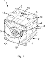
- FIG 1 an exemplary embodiment of a fan 1 as an axial fan with two counter-rotating fan wheels 5 is shown in a perspective view.
- the fan 1 comprises two motors, each of which drives a fan wheel 5 arranged in the flow channel, and a multi-part fan housing 2, which forms the flow channel.
- the fan housing 2 is formed by a first axial part 3, a second axial part 4 and an intermediate part 15, which is arranged between the two axial parts 3, 4 as viewed along the axis of rotation RA.
- figure 4 shows the structure in a sectional view for better understanding.
- Two sockets 27 are formed on the intermediate piece to accommodate one motor and one impeller 5 each, which are arranged in the flow channel of the fan housing 2 .
- the disclosure expressly also includes solutions that do not use an intermediate piece, but rather arrange the first and second axial parts 3, 4 directly next to one another.
- the first axial part 3 forms the flow intake section, the second axial part 4 the flow exhaust section of the fan 1.
- the fan housing 2 has an essentially square basic shape.
- housing covers 6 are arranged on the outer lateral surface of the fan housing 2, which form the corner.
- the housing covers 6 connect and fasten the first axial part 3 to the second axial part 4 by means of screws.
- the housing covers 6 are shaped in such a way that they supplement the basic shape and each form a receiving space 7 with the outer lateral surface of the fan housing 2, in which an exemplary in figure 3 circuit board 20 shown are arranged with motor electronic components for the motor.
- a separate printed circuit board 20 is used for each motor. In the case of solutions with only one motor, therefore, only one housing cover 6 can be used and a printed circuit board 20 can be positioned in the receiving space 7 formed by the one housing cover 6 .
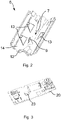
- FIG 2 in combination with figure 1 the multifunctionality of the housing covers 6 is shown.
- a rib 12 is formed which protrudes into the receiving space 7 in the assembled state and on which the connecting cable 11 is brought into contact in the pocket 8 and is therefore fixed in such a way that strain relief of the connecting plug 10 is ensured.
- the connection cable 11 of the connection plug 10 is also fixed in the pocket 8 by the printed circuit board 20 and the rib 12 .
- Circuit board 20 shown is connected to the windings of the motor via a winding connector (not shown).
- a socket 23 for the winding connector is provided on the printed circuit board 20 .
- the printed circuit board 20 is arranged in the receiving space 7 formed by the housing cover 6 in such a way that the figure 2 shown, in the mounted state of the housing cover 6 in the receiving space 7 protruding retaining web 9 acts on the winding connector fixing and fixes its mounting position in the socket 23.
- the holding web 9 presses the winding connector against the printed circuit board 20.
- the printed circuit boards 20 are additionally fastened in the respective receiving space 7 by means of elastically resilient legs 13 formed on the housing covers 6.
- the legs 13 are designed as a partial opening in the housing cover wall 14 and press the printed circuit boards 20 into their respective assembly position with a certain material-related prestress.
- the housing cover 6 can also be designed without legs 13 .
Landscapes
- Engineering & Computer Science (AREA)
- Mechanical Engineering (AREA)
- General Engineering & Computer Science (AREA)
- Structures Of Non-Positive Displacement Pumps (AREA)
Abstract
Description
- Die Erfindung betrifft einen Lüfter mit mindestens einem Motor sowie mindestens einem um eine Rotationsachse rotierbaren Lüfterrad und einem mehrteiligen Lüftergehäuse mit einer multifunktionalen Gehäuseabdeckung.
- Aus dem Stand der Technik ist eine Vielzahl von Lüfter mit verschiedenen Gehäusearten bekannt. Derartige Gehäuse sind jedoch vor allem dahingehend konstruiert, die Lüfterräder auszunehmen und den Strömungskanal zu bilden, ohne dass weitere Funktionen integriert sind.
- Der Erfindung liegt deshalb die Aufgabe zugrunde, einen Lüfter mit einem Lüftergehäuse bereitzustellen, das mehrere Funktionen aufweist und technisch mit antriebsbedingt nötigen Komponenten zusammenwirkt.
- Diese Aufgabe wird durch die Merkmalskombination gemäß Patentanspruch 1 gelöst.
- Erfindungsgemäß wird ein Lüfter mit mindestens einem Motor sowie mindestens einem um eine Rotationsachse rotierbaren Lüfterrad und einem mehrteiligen Lüftergehäuse vorgeschlagen. Das Lüftergehäuse bildet einen Strömungskanal, in dem das mindestens eine Lüfterrad angeordnet ist. Zudem weist das Lüftergehäuse zumindest ein erstes Axialteil und ein zweites Axialteil auf, die in axialer Richtung entlang der Rotationsachse gesehen zueinander angeordnet sind. Der Lüfter umfasst ferner mindestens eine Gehäuseabdeckung, die an einer Außenmantelfläche des Lüftergehäuses angeordnet ist und das erste Axialteil und das zweite Axialteil miteinander verbindet. Die mindestens eine Gehäuseabdeckung bildet zudem mit der Außenmantelfläche des Lüftergehäuses einen Aufnahmeraum, in dem eine Leiterplatte mit einer Motorelektronik für den Motor angeordnet ist.
- Die multifunktionale Gehäuseabdeckung wirkt mit den Axialteilen des Lüftergehäuses zusammen, in dem sie die beiden Axialteile verbindet und mithin die Gesamtkonstruktion stabilisiert. Gleichzeitig ermöglicht der durch die Gehäuseabdeckung gebildete Aufnahmeraum die Anordnung der Leiterplatte mit der Motorelektronik außerhalb der Strömung des Lüfters. Zudem wird als weitere Funktion der Gehäuseabdeckung die Leiterplatte vor Berührung geschützt. Die Leiterplatte kann an einem oder beiden Axialteilen leicht montiert und anschließend von der Gehäuseabdeckung abgedeckt und in den Aufnahmeraum eingeschlossen werden. Zudem ist in einer Ausführung eine Fixierung der Leiterplatte durch die Gehäuseabdeckung an einem oder beiden Axialteilen realisierbar.
- Bei dem Lüfter ist ferner in einer Ausführungsvariante vorgesehen, dass das erste Axialteil und das zweite Axialteil durch die mindestens eine Gehäuseabdeckung aneinander befestigt, insbesondere verschraubt sind. Die Gehäuseabdeckung ist mithin das vermittelnde Bauteil zur Herstellung der Verbindung und Befestigung zwischen dem ersten und zweiten Axialteil.
- Bei dem Lüfter bestimmt vorzugsweise das erste Axialteil einen Strömungsansaugabschnitt und das zweite Axialteil einen Strömungsausblasabschnitt des Lüfters. Die beiden Axialteile sind mithin die Hauptelemente des Lüftergehäuses.
- Der Lüfter ist in einer vorteilhaften Weiterbildung dadurch gekennzeichnet, dass das erste und/oder zweite Axialteil eine Tasche zur Aufnahme eines mit der Leiterplatte verbundenen Anschlusssteckers des Lüfters bzw. eines Anschlusskabels des Anschlusssteckers und die mindestens eine Gehäuseabdeckung eine in den Aufnahmeraum hineinragende Rippe aufweisen. Dabei ist vorgesehen, dass die Rippe das Anschlusskabel und mithin den Anschlussstecker zugentlastend in der Tasche festlegt. Somit ist sichergestellt, dass auf den Anschlussstecker zum elektrischen Anschluss des Lüfters wirkende Zugkräfte nicht unmittelbar auf die elektronischen Bauteile einwirken, sondern von der Gehäuseabdeckung und dem Axialteil mit der Tasche aufgenommen werden. Hierzu wird insbesondere das an dem Anschlussstecker angreifende Anschlusskabel in die Tasche eingelegt und durch die Rippe in der Tasche gepresst gehalten.
- Als Weiterbildung ist beidem Lüfter zudem vorgesehen, dass das Anschlusskabel des Anschlusssteckers durch die Leiterplatte und die Rippe in der Tasche fixiert ist. Eine derartige Lösung ist noch effektiver, da die Leiterplatte eine zusätzlich Haltekraft auf das Anschlusskabel ausübt und mithin die Fixierung und Zugentlastung verbessert sind.
- Als weitere vorteilhafte Ausgestaltung ist der Lüfter dadurch gekennzeichnet, dass die mindestens eine Gehäuseabdeckung eine in den Aufnahmeraum hineinragenden Haltesteg aufweist, der ausgebildet ist, einen Wicklungsstecker des Motors bezüglich seiner Position im Aufnahmeraum fixiert an der Leiterplatte festzulegen. Der Wicklungsstecker des Motors wird an der Leiterplatte fixiert. Da es im Betrieb des Lüfters zu Schwingungen und Vibrationen kommt, ist es günstig, eine zusätzliche Fixierung bereitzustellen. Diese wird in die Gehäuseabdeckung integriert, in dem der Haltesteg derart positioniert und dimensioniert ist, dass er bei einer bestimmungsgemäß montierten Gehäuseabdeckung an den Wicklungsstecker angreift und diesen in seiner Position festlegt. Hierzu können der Haltesteg und der Wicklungsstecker zusätzlich haltend zusammenwirkende Geometrien aufweisen.
- Der Lüfter weist in einer Ausführungsvariante in einer axialen Draufsicht eine rechtwinklige oder quadratische Grundform auf. Die mindestens eine Gehäuseabdeckung erstreckt sich dann entlang einer Ecke der Grundform in axialer Richtung über das erste Axialteil und das zweite Axialteil. Insbesondere wird die Gehäuseabdeckung an einer äußeren Mantelfläche der Axialteile angeordnet und bestimmt die Außengeometrie des Lüfters in der jeweiligen Ecke.
- Als weitere vorteilhafte Ausgestaltung ist der Lüfter dadurch gekennzeichnet, dass an der Gehäuseabdeckung mindestens ein elastisch federnder Schenkel vorgesehen ist, der als Teildurchbruch einer Gehäuseabdeckungswandung ausgebildet ist, in den Aufnahmeraum hineinragt und vorgespannt an die Leiterplatte angreift. Die Gehäuseabdeckung liefert dadurch die weitere Funktion der federnden Arretierung der Leiterplatte. Dies ist im Betrieb des Lüfters mit Vibrationen und Schwingungen besonders günstig.
- Bei einer weiteren Weiterbildung des Lüfters weist das Lüftergehäuse axial zwischen dem ersten Axialteil und dem zweiten Axialteil ein Zwischenstück auf, das einen Teil des Strömungskanals und der Außenmantelfläche des Lüftergehäuses bildet. Die Gehäuseabdeckung überspannt dann vorteilhafterweise sowohl die Axialteile als auch das Zwischenstück. Derartige Zwischenstücke werden beispielsweise bei der Verwendung mehreren axial in riehe angeordneten Lüfterrädern eingesetzt.
- Deshalb sind in einem Ausführungsbeispiel der vorliegenden Offenbarung an dem Zwischenstück auf beiden axialen Seiten jeweils ein Motor und ein Lüfterrad angeordnet. An dem Lüftergehäuse sind zudem zwei Gehäuseabdeckungen angeordnet, die jeweils mit dem Lüftergehäuse einen eigenen Aufnahmeraum bilden und in jedem der Aufnahmeräume eine Leiterplatte für einen Motor angeordnet ist. Die vorstehend für die Gehäuseabdeckung beschriebenen Merkmale sind vollumfänglich auf beide Gehäuseabdeckungen anwendbar.
- Andere vorteilhafte Weiterbildungen der Erfindung sind in den Unteransprüchen gekennzeichnet bzw. werden nachstehend zusammen mit der Beschreibung der bevorzugten Ausführung der Erfindung anhand der Figuren näher dargestellt. Es zeigen:
- Fig. 1
- eine perspektivische Ansicht auf einen Lüfter;
- Fig. 2
- eine Detailansicht einer Gehäuseabdeckung;
- Fig. 3
- eine beispielhafte Leiterplatte;
- Fig. 4
- eine Schnittansicht durch das Lüftergehäuse.
- Die Figuren sind beispielhaft schematisch. Gleiche Bezugszeichen in den Figuren weisen auf gleiche funktionale und/oder strukturelle Merkmale hin.
- In
Figur 1 ist ein Ausführungsbeispiel eines Lüfters 1 als Axiallüfter mit zwei gegenläufig rotierenden Lüfterrädern 5 in perspektivischer Ansicht dargestellt. Die Erfindung ist jedoch auch auf andere Lüfterbauarten, insbesondere Axiallüfter mit nur einem Lüfterrad anwendbar. Der Lüfter 1 umfasst zwei Motoren, die jeweils ein im Strömungskanal angeordnetes Lüfterrad 5 antreiben, und ein mehrteiliges Lüftergehäuse 2, das den Strömungskanal bildet. - Das Lüftergehäuse 2 ist in der gezeigten Ausführung durch ein erstes Axialteil 3, ein zweites Axialteil 4 und ein Zwischenstück 15, das entlang der Rotationsachse RA gesehen zwischen den beiden Axialteilen 3, 4 angeordnet ist, gebildet.
Figur 4 zeigt den Aufbau zum besseren Verständnis in einer Schnittansicht. An dem Zwischenstück sind zwei Stutzen 27 zur Aufnahme je eines Motors und eines Laufrads 5 ausgebildet, die im Strömungskanal des Lüftergehäuses 2 angeordnet sind. Ausdrücklich sind jedoch auch Lösungen von der Offenbarung umfasst, die kein Zwischenstück verwenden, sondern die das erste und zweite Axialteil 3, 4 unmittelbar aneinander anordnen. Das erste Axialteil 3 bildet den Strömungsansaugabschnitt, das zweite Axialteil 4 den Strömungsausblasabschnitt des Lüfters 1. Das Lüftergehäuse 2 weist eine im Wesentlichen quadratische Grundform auf. In zwei der Ecken der Grundform sind an der Außenmantelfläche des Lüftergehäuses 2 jeweils Gehäuseabdeckungen 6 angeordnet, welche die Ecke bilden. Die Gehäuseabdeckungen 6 verbinden und befestigen das erste Axialteil 3 mit dem zweiten Axialteil 4 mittels Schrauben. Die Gehäuseabdeckungen 6 sind derart geformt, dass sie die Grundform ergänzen und mit der Außenmantelfläche des Lüftergehäuses 2 jeweils einen Aufnahmeraum 7 bilden, in dem jeweils eine exemplarisch inFigur 3 gezeigte Leiterplatte 20 mit Motorelektronikbauteilen für den Motor angeordnet sind. Für jeden Motor wird eine eigene Leiterplatte 20 verwendet. Bei Lösungen mit nur einem Motor kann mithin nur eine Gehäuseabdeckung 6 verwendet werden und in dem durch die eine Gehäuseabdeckung 6 gebildeten Aufnahmeraum 7 eine Leiterplatte 20 positioniert werden. - Bezugnehmend auf
Figur 2 in Kombination mitFigur 1 ist die Multifunktionalität der Gehäuseabdeckungen 6 dargestellt. Neben der Abdeckung und der Bildung des Aufnahmeraums 7 umfasst zumindest eine Gehäuseabdeckungen 6 eine Tasche 8 zur Aufnahme des mit der Leiterplatte 20 verbundenen Anschlusskabels 11 des Anschlusssteckers 10 des Lüfters 1. An der inFigur 2 im Detail dargestellten Gehäuseabdeckung 6 ist eine im montierten Zustand in den Aufnahmeraum 7 hineinragende Rippe 12 ausgebildet, an welcher das Anschlusskabel 11 in der Tasche 8 zur Anlage gebracht und mithin so fixiert wird, dass eine Zugentlastung des Anschlusssteckers 10 gewährleistet ist. Zudem wird das Anschlusskabel 11 des Anschlusssteckers 10 auch durch die Leiterplatte 20 und die Rippe 12 in der Tasche 8 fixiert. - Die in
Figur 3 gezeigte Leiterplatte 20 wird über einen Wicklungsstecker (nicht gezeigt) mit den Wicklungen des Motors verbunden. Hierzu ist an der Leiterplatte 20 eine Steckbuchse 23 für den Wicklungsstecker vorgesehen. Die Leiterplatte 20 ist derart in dem durch die Gehäuseabdeckung 6 gebildeten Aufnahmeraum 7 angeordnet, dass der inFigur 2 gezeigte, im montierten Zustand der Gehäuseabdeckung 6 in den Aufnahmeraum 7 hineinragende Haltesteg 9 auf den Wicklungsstecker fixierend einwirkt und seine Montageposition in der Steckbuchse 23 fixiert. Der Haltesteg 9 drückt den Wicklungsstecker dabei gegen die Leiterplatte 20. Über an den Gehäuseabdeckungen 6 ausgebildete elastisch federnde Schenkel 13 werden die Leiterplatten 20 im jeweiligen Aufnahmeraum 7 zusätzlich befestigt. Die Schenkel 13 sind dabei als Teildurchbruch der Gehäuseabdeckungswandung 14 ausgebildet und drücken die Leiterplatten 20 mit einer gewissen materialbedingten Vorspannung in ihre jeweilige Montageposition. - Weitere nicht dargestellte Ausführungsvarianten nutzen nur Teilaspekte der beschriebenen oder in den Figuren gezeigten Merkmale, gehören jedoch gelichwohl zur Offenbarung. So kann die Gehäuseabdeckung 6 beispielsweise auch ohne Schenkel 13 ausgeführt sein.
Claims (10)
- Lüfter (1) mit mindestens einem Motor sowie mindestens einem um eine Rotationsachse (RA) rotierbaren Lüfterrad (5) und einem mehrteiligen Lüftergehäuse (2), das einen Strömungskanal bildet, in dem das mindestens eine Lüfterrad (5) angeordnet ist, wobei das Lüftergehäuse (2) zumindest ein erstes Axialteil (3) und ein zweites Axialteil (4) aufweist, die in axialer Richtung entlang der Rotationsachse (RA) gesehen zueinander angeordnet sind, wobei der Lüfter (1) mindestens eine Gehäuseabdeckung (6) aufweist, die an einer Außenmantelfläche des Lüftergehäuses (2) angeordnet ist und das erste Axialteil (3) und das zweite Axialteil (4) miteinander verbindet, wobei die mindestens eine Gehäuseabdeckung (6) mit der Außenmantelfläche des Lüftergehäuses (2) einen Aufnahmeraum (7) bildet, in dem eine Leiterplatte (20) mit einer Motorelektronik für den Motor angeordnet ist.
- Lüfter nach Anspruch 1, dadurch gekennzeichnet, dass das erste Axialteil (3) und das zweite Axialteil (4) durch die mindestens eine Gehäuseabdeckung (6) aneinander befestigt sind.
- Lüfter nach Anspruch 1 oder 2, dadurch gekennzeichnet, dass das erste Axialteil (3) einen Strömungsansaugabschnitt des Lüfters (1) und das zweite Axialteil (4) einen Strömungsausblasabschnitt des Lüfters (1) bestimmen.
- Lüfter nach einem der vorigen Ansprüche, dadurch gekennzeichnet, dass das erste oder zweite Axialteil (3, 4) eine Tasche (8) zur Aufnahme eines mit der Leiterplatte (20) verbundenen Anschlusskabels (11) eines Anschlusssteckers (10) des Lüfters (1) und die Gehäuseabdeckung (6) mindestens eine in den Aufnahmeraum hineinragende Rippe (12) aufweist, wobei die Rippe (12) den Anschlussstecker (10) zugentlastend in der Tasche (8) festlegt.
- Lüfter nach dem vorigen Anspruch, dadurch gekennzeichnet, dass das Anschlusskabel (11) des Anschlusssteckers (10) durch die Leiterplatte (20) und die Rippe (12) in der Tasche (8) fixiert ist.
- Lüfter nach einem der vorigen Ansprüche, dadurch gekennzeichnet, dass die mindestens eine Gehäuseabdeckung (6) eine in den Aufnahmeraum (7) hineinragenden Haltesteg (9) aufweist, der ausgebildet ist, einen Wicklungsstecker des Motors bezüglich seiner Position im Aufnahmeraum (7) fixiert an der Leiterplatte festzulegen.
- Lüfter nach einem der vorigen Ansprüche, dadurch gekennzeichnet, dass der Lüfter (1) in einer axialen Draufsicht eine rechtwinklige oder quadratische Grundform aufweist und die mindestens eine Gehäuseabdeckung (6) sich entlang einer Ecke der Grundform in axialer Richtung über das erste Axialteil (3) und das zweite Axialteil (4) erstreckt.
- Lüfter nach einem der vorigen Ansprüche, dadurch gekennzeichnet, dass an der Gehäuseabdeckung (6) mindestens ein elastisch federnder Schenkel (13) vorgesehen ist, der als Teildurchbruch einer Gehäuseabdeckungswandung (14) ausgebildet ist und in den Aufnahmeraum (7) hineinragt und vorgespannt an die Leiterplatte (20) angreift.
- Lüfter nach einem der vorigen Ansprüche, dadurch gekennzeichnet, dass das Lüftergehäuse (2) axial zwischen dem ersten Axialteil (3) und dem zweiten Axialteil (4) ein Zwischenstück (15) aufweist, das einen Teil des Strömungskanals und der Außenmantelfläche des Lüftergehäuses (2) bildet.
- Lüfter nach dem vorigen Anspruch, dadurch gekennzeichnet, dass an dem Zwischenstück (15) auf beiden axialen Seiten jeweils ein Motor und ein Lüfterrad (5) angeordnet sind, wobei an dem Lüftergehäuse (2) zwei Gehäuseabdeckungen (6) angeordnet sind, die jeweils mit dem Lüftergehäuse (2) einen eigenen Aufnahmeraum (7) bilden und in jedem der Aufnahmeräume (7) eine Leiterplatte (20) für je einen Motor angeordnet ist.
Applications Claiming Priority (1)
| Application Number | Priority Date | Filing Date | Title |
|---|---|---|---|
| DE102021107359.6A DE102021107359A1 (de) | 2021-03-24 | 2021-03-24 | Lüfter mit multifunktionaler Gehäuseabdeckung |
Publications (2)
| Publication Number | Publication Date |
|---|---|
| EP4063661A1 true EP4063661A1 (de) | 2022-09-28 |
| EP4063661B1 EP4063661B1 (de) | 2024-09-18 |
Family
ID=80682983
Family Applications (1)
| Application Number | Title | Priority Date | Filing Date |
|---|---|---|---|
| EP22160566.0A Active EP4063661B1 (de) | 2021-03-24 | 2022-03-07 | Lüfter mit multifunktionaler gehäuseabdeckung |
Country Status (3)
| Country | Link |
|---|---|
| EP (1) | EP4063661B1 (de) |
| DE (1) | DE102021107359A1 (de) |
| FI (1) | FI4063661T3 (de) |
Citations (6)
| Publication number | Priority date | Publication date | Assignee | Title |
|---|---|---|---|---|
| US20020067597A1 (en) * | 2000-12-06 | 2002-06-06 | Delta Electronics, Inc. | Heat-dissipating assembly |
| US20030019646A1 (en) * | 2001-07-30 | 2003-01-30 | Clements Bradley Edgar | Mounting apparatus for coupling control circuitry to an air moving device |
| EP1561037B1 (de) * | 2002-11-15 | 2006-03-01 | ebm-papst St. Georgen GmbH & Co. KG | Lüfter, insbesondere gerätelüfter |
| DE202010006891U1 (de) * | 2009-05-28 | 2010-10-21 | Ebm-Papst St. Georgen Gmbh & Co. Kg | Gerätelüfter |
| US20160097396A1 (en) * | 2014-10-07 | 2016-04-07 | Nidec Corporation | Axial flow fan |
| US20160245306A1 (en) * | 2013-10-01 | 2016-08-25 | Ebm-Papst St. Georgen Gmbh & Co. Kg | Fan device and use of such a fan device |
-
2021
- 2021-03-24 DE DE102021107359.6A patent/DE102021107359A1/de active Pending
-
2022
- 2022-03-07 EP EP22160566.0A patent/EP4063661B1/de active Active
- 2022-03-07 FI FIEP22160566.0T patent/FI4063661T3/en active
Patent Citations (6)
| Publication number | Priority date | Publication date | Assignee | Title |
|---|---|---|---|---|
| US20020067597A1 (en) * | 2000-12-06 | 2002-06-06 | Delta Electronics, Inc. | Heat-dissipating assembly |
| US20030019646A1 (en) * | 2001-07-30 | 2003-01-30 | Clements Bradley Edgar | Mounting apparatus for coupling control circuitry to an air moving device |
| EP1561037B1 (de) * | 2002-11-15 | 2006-03-01 | ebm-papst St. Georgen GmbH & Co. KG | Lüfter, insbesondere gerätelüfter |
| DE202010006891U1 (de) * | 2009-05-28 | 2010-10-21 | Ebm-Papst St. Georgen Gmbh & Co. Kg | Gerätelüfter |
| US20160245306A1 (en) * | 2013-10-01 | 2016-08-25 | Ebm-Papst St. Georgen Gmbh & Co. Kg | Fan device and use of such a fan device |
| US20160097396A1 (en) * | 2014-10-07 | 2016-04-07 | Nidec Corporation | Axial flow fan |
Also Published As
| Publication number | Publication date |
|---|---|
| DE102021107359A1 (de) | 2022-09-29 |
| FI4063661T3 (en) | 2024-12-13 |
| EP4063661B1 (de) | 2024-09-18 |
Similar Documents
| Publication | Publication Date | Title |
|---|---|---|
| EP3164911B1 (de) | Steckverbinder | |
| DE102016122084A1 (de) | Elektronische Schaltungseinheit | |
| WO2022053379A1 (de) | Gehäuse für eine auf einer leiterplatte angeordneten elektronische schaltung | |
| DE10111777A1 (de) | Leiterplatten-Verbinder | |
| DE202009003648U1 (de) | Montagehilfe für Leiterplattensteckverbinder | |
| EP4063661B1 (de) | Lüfter mit multifunktionaler gehäuseabdeckung | |
| DE7630468U1 (de) | Schutzleiteranschluss fuer motoren, insbesondere kleinmotoren | |
| DE102014115384A1 (de) | Prüfkabel sowie Buchsenadapter für ein Prüfkabel | |
| EP2648285B1 (de) | Steckverbinder zur Montage in eine Gehäuseöffnung eines Gehäuses | |
| EP4270675B1 (de) | Festpoliger kontakteinsatz und kontakteinsatzanordnung | |
| EP3977826B1 (de) | Vorrichtung mit einer stromschienenanordnung, einer filtervorrichtung und einer abdeckung, zugehöriges herstellungsverfahren sowie stromrichter und antriebseinrichtung | |
| DE102020100988A1 (de) | Baugruppe mit orthogonal zur Montagerichtung der Baugruppe montierbaren Steckverbinder | |
| DE102024113827B3 (de) | Elektronikvorrichtung | |
| DE102023128532A1 (de) | Isolationsschutz für einen Wechselrichter gegen Stromschlaggefahr | |
| DE102024121668A1 (de) | Anbaueinheit für einen Elektromotor und Elektromotor mit Anbaueinheit | |
| EP1603381A1 (de) | Federblech in einem Gehäuse als Abschirmung für ein elektronisches hochfrequenztechnisches Gerät | |
| DE102009059011A1 (de) | Verbindungssystem zum Verbinden eines einreihigen Gehäuses mit einem Anschlusselement | |
| EP1040276A1 (de) | Lüfter | |
| DE102019100051B4 (de) | Bauraumreduziertes Steckverbindergehäuse, Steckverbinderflansch sowie Steckverbindungssystem | |
| DE102024131300A1 (de) | Haltevorrichtung und damit gebildete Einrichtung | |
| DE102024128410A1 (de) | Kabelbaum | |
| DE202023107084U1 (de) | Befestigungsvorrichtung und damit gebildete Einrichtung | |
| DE10319173A1 (de) | Bürstenträger für eine elektrische Maschine | |
| DE102022110022A1 (de) | Festpoliger Kontakteinsatz und Kontakteinsatzanordnung | |
| DE112023004771T5 (de) | Elektronikkomponenteneinheit und Kabelbaum |
Legal Events
| Date | Code | Title | Description |
|---|---|---|---|
| PUAI | Public reference made under article 153(3) epc to a published international application that has entered the european phase |
Free format text: ORIGINAL CODE: 0009012 |
|
| STAA | Information on the status of an ep patent application or granted ep patent |
Free format text: STATUS: THE APPLICATION HAS BEEN PUBLISHED |
|
| AK | Designated contracting states |
Kind code of ref document: A1 Designated state(s): AL AT BE BG CH CY CZ DE DK EE ES FI FR GB GR HR HU IE IS IT LI LT LU LV MC MK MT NL NO PL PT RO RS SE SI SK SM TR |
|
| STAA | Information on the status of an ep patent application or granted ep patent |
Free format text: STATUS: REQUEST FOR EXAMINATION WAS MADE |
|
| 17P | Request for examination filed |
Effective date: 20230314 |
|
| RBV | Designated contracting states (corrected) |
Designated state(s): AL AT BE BG CH CY CZ DE DK EE ES FI FR GB GR HR HU IE IS IT LI LT LU LV MC MK MT NL NO PL PT RO RS SE SI SK SM TR |
|
| GRAP | Despatch of communication of intention to grant a patent |
Free format text: ORIGINAL CODE: EPIDOSNIGR1 |
|
| STAA | Information on the status of an ep patent application or granted ep patent |
Free format text: STATUS: GRANT OF PATENT IS INTENDED |
|
| INTG | Intention to grant announced |
Effective date: 20240508 |
|
| GRAS | Grant fee paid |
Free format text: ORIGINAL CODE: EPIDOSNIGR3 |
|
| GRAA | (expected) grant |
Free format text: ORIGINAL CODE: 0009210 |
|
| STAA | Information on the status of an ep patent application or granted ep patent |
Free format text: STATUS: THE PATENT HAS BEEN GRANTED |
|
| P01 | Opt-out of the competence of the unified patent court (upc) registered |
Free format text: CASE NUMBER: APP_43120/2024 Effective date: 20240723 |
|
| AK | Designated contracting states |
Kind code of ref document: B1 Designated state(s): AL AT BE BG CH CY CZ DE DK EE ES FI FR GB GR HR HU IE IS IT LI LT LU LV MC MK MT NL NO PL PT RO RS SE SI SK SM TR |
|
| REG | Reference to a national code |
Ref country code: GB Ref legal event code: FG4D Free format text: NOT ENGLISH |
|
| REG | Reference to a national code |
Ref country code: CH Ref legal event code: EP |
|
| REG | Reference to a national code |
Ref country code: IE Ref legal event code: FG4D Free format text: LANGUAGE OF EP DOCUMENT: GERMAN |
|
| REG | Reference to a national code |
Ref country code: DE Ref legal event code: R096 Ref document number: 502022001676 Country of ref document: DE |
|
| REG | Reference to a national code |
Ref country code: FI Ref legal event code: FGE |
|
| REG | Reference to a national code |
Ref country code: NL Ref legal event code: FP |
|
| REG | Reference to a national code |
Ref country code: SE Ref legal event code: TRGR |
|
| REG | Reference to a national code |
Ref country code: LT Ref legal event code: MG9D |
|
| PG25 | Lapsed in a contracting state [announced via postgrant information from national office to epo] |
Ref country code: GR Free format text: LAPSE BECAUSE OF FAILURE TO SUBMIT A TRANSLATION OF THE DESCRIPTION OR TO PAY THE FEE WITHIN THE PRESCRIBED TIME-LIMIT Effective date: 20241219 |
|
| PG25 | Lapsed in a contracting state [announced via postgrant information from national office to epo] |
Ref country code: BG Free format text: LAPSE BECAUSE OF FAILURE TO SUBMIT A TRANSLATION OF THE DESCRIPTION OR TO PAY THE FEE WITHIN THE PRESCRIBED TIME-LIMIT Effective date: 20240918 |
|
| PG25 | Lapsed in a contracting state [announced via postgrant information from national office to epo] |
Ref country code: LV Free format text: LAPSE BECAUSE OF FAILURE TO SUBMIT A TRANSLATION OF THE DESCRIPTION OR TO PAY THE FEE WITHIN THE PRESCRIBED TIME-LIMIT Effective date: 20240918 |
|
| PG25 | Lapsed in a contracting state [announced via postgrant information from national office to epo] |
Ref country code: HR Free format text: LAPSE BECAUSE OF FAILURE TO SUBMIT A TRANSLATION OF THE DESCRIPTION OR TO PAY THE FEE WITHIN THE PRESCRIBED TIME-LIMIT Effective date: 20240918 |
|
| PG25 | Lapsed in a contracting state [announced via postgrant information from national office to epo] |
Ref country code: RS Free format text: LAPSE BECAUSE OF FAILURE TO SUBMIT A TRANSLATION OF THE DESCRIPTION OR TO PAY THE FEE WITHIN THE PRESCRIBED TIME-LIMIT Effective date: 20241218 |
|
| PG25 | Lapsed in a contracting state [announced via postgrant information from national office to epo] |
Ref country code: RS Free format text: LAPSE BECAUSE OF FAILURE TO SUBMIT A TRANSLATION OF THE DESCRIPTION OR TO PAY THE FEE WITHIN THE PRESCRIBED TIME-LIMIT Effective date: 20241218 Ref country code: LV Free format text: LAPSE BECAUSE OF FAILURE TO SUBMIT A TRANSLATION OF THE DESCRIPTION OR TO PAY THE FEE WITHIN THE PRESCRIBED TIME-LIMIT Effective date: 20240918 Ref country code: HR Free format text: LAPSE BECAUSE OF FAILURE TO SUBMIT A TRANSLATION OF THE DESCRIPTION OR TO PAY THE FEE WITHIN THE PRESCRIBED TIME-LIMIT Effective date: 20240918 Ref country code: GR Free format text: LAPSE BECAUSE OF FAILURE TO SUBMIT A TRANSLATION OF THE DESCRIPTION OR TO PAY THE FEE WITHIN THE PRESCRIBED TIME-LIMIT Effective date: 20241219 Ref country code: BG Free format text: LAPSE BECAUSE OF FAILURE TO SUBMIT A TRANSLATION OF THE DESCRIPTION OR TO PAY THE FEE WITHIN THE PRESCRIBED TIME-LIMIT Effective date: 20240918 |
|
| PG25 | Lapsed in a contracting state [announced via postgrant information from national office to epo] |
Ref country code: PT Free format text: LAPSE BECAUSE OF FAILURE TO SUBMIT A TRANSLATION OF THE DESCRIPTION OR TO PAY THE FEE WITHIN THE PRESCRIBED TIME-LIMIT Effective date: 20250120 Ref country code: IS Free format text: LAPSE BECAUSE OF FAILURE TO SUBMIT A TRANSLATION OF THE DESCRIPTION OR TO PAY THE FEE WITHIN THE PRESCRIBED TIME-LIMIT Effective date: 20250118 |
|
| PG25 | Lapsed in a contracting state [announced via postgrant information from national office to epo] |
Ref country code: RO Free format text: LAPSE BECAUSE OF FAILURE TO SUBMIT A TRANSLATION OF THE DESCRIPTION OR TO PAY THE FEE WITHIN THE PRESCRIBED TIME-LIMIT Effective date: 20240918 Ref country code: SM Free format text: LAPSE BECAUSE OF FAILURE TO SUBMIT A TRANSLATION OF THE DESCRIPTION OR TO PAY THE FEE WITHIN THE PRESCRIBED TIME-LIMIT Effective date: 20240918 |
|
| PG25 | Lapsed in a contracting state [announced via postgrant information from national office to epo] |
Ref country code: ES Free format text: LAPSE BECAUSE OF FAILURE TO SUBMIT A TRANSLATION OF THE DESCRIPTION OR TO PAY THE FEE WITHIN THE PRESCRIBED TIME-LIMIT Effective date: 20240918 |
|
| PG25 | Lapsed in a contracting state [announced via postgrant information from national office to epo] |
Ref country code: EE Free format text: LAPSE BECAUSE OF FAILURE TO SUBMIT A TRANSLATION OF THE DESCRIPTION OR TO PAY THE FEE WITHIN THE PRESCRIBED TIME-LIMIT Effective date: 20240918 |
|
| PG25 | Lapsed in a contracting state [announced via postgrant information from national office to epo] |
Ref country code: PL Free format text: LAPSE BECAUSE OF FAILURE TO SUBMIT A TRANSLATION OF THE DESCRIPTION OR TO PAY THE FEE WITHIN THE PRESCRIBED TIME-LIMIT Effective date: 20240918 Ref country code: CZ Free format text: LAPSE BECAUSE OF FAILURE TO SUBMIT A TRANSLATION OF THE DESCRIPTION OR TO PAY THE FEE WITHIN THE PRESCRIBED TIME-LIMIT Effective date: 20240918 |
|
| PG25 | Lapsed in a contracting state [announced via postgrant information from national office to epo] |
Ref country code: SK Free format text: LAPSE BECAUSE OF FAILURE TO SUBMIT A TRANSLATION OF THE DESCRIPTION OR TO PAY THE FEE WITHIN THE PRESCRIBED TIME-LIMIT Effective date: 20240918 |
|
| REG | Reference to a national code |
Ref country code: DE Ref legal event code: R097 Ref document number: 502022001676 Country of ref document: DE |
|
| PG25 | Lapsed in a contracting state [announced via postgrant information from national office to epo] |
Ref country code: DK Free format text: LAPSE BECAUSE OF FAILURE TO SUBMIT A TRANSLATION OF THE DESCRIPTION OR TO PAY THE FEE WITHIN THE PRESCRIBED TIME-LIMIT Effective date: 20240918 |
|
| PGFP | Annual fee paid to national office [announced via postgrant information from national office to epo] |
Ref country code: IT Payment date: 20250331 Year of fee payment: 4 |
|
| PLBE | No opposition filed within time limit |
Free format text: ORIGINAL CODE: 0009261 |
|
| STAA | Information on the status of an ep patent application or granted ep patent |
Free format text: STATUS: NO OPPOSITION FILED WITHIN TIME LIMIT |
|
| 26N | No opposition filed |
Effective date: 20250619 |
|
| PG25 | Lapsed in a contracting state [announced via postgrant information from national office to epo] |
Ref country code: MC Free format text: LAPSE BECAUSE OF FAILURE TO SUBMIT A TRANSLATION OF THE DESCRIPTION OR TO PAY THE FEE WITHIN THE PRESCRIBED TIME-LIMIT Effective date: 20240918 |
|
| REG | Reference to a national code |
Ref country code: CH Ref legal event code: H13 Free format text: ST27 STATUS EVENT CODE: U-0-0-H10-H13 (AS PROVIDED BY THE NATIONAL OFFICE) Effective date: 20251023 |
|
| PG25 | Lapsed in a contracting state [announced via postgrant information from national office to epo] |
Ref country code: LU Free format text: LAPSE BECAUSE OF NON-PAYMENT OF DUE FEES Effective date: 20250307 |
|
| REG | Reference to a national code |
Ref country code: BE Ref legal event code: MM Effective date: 20250331 |
|
| PG25 | Lapsed in a contracting state [announced via postgrant information from national office to epo] |
Ref country code: BE Free format text: LAPSE BECAUSE OF NON-PAYMENT OF DUE FEES Effective date: 20250331 |
|
| PG25 | Lapsed in a contracting state [announced via postgrant information from national office to epo] |
Ref country code: CH Free format text: LAPSE BECAUSE OF NON-PAYMENT OF DUE FEES Effective date: 20250331 |
|
| PG25 | Lapsed in a contracting state [announced via postgrant information from national office to epo] |
Ref country code: IE Free format text: LAPSE BECAUSE OF NON-PAYMENT OF DUE FEES Effective date: 20250307 |
|
| PGFP | Annual fee paid to national office [announced via postgrant information from national office to epo] |
Ref country code: SE Payment date: 20260323 Year of fee payment: 5 |
|
| PGFP | Annual fee paid to national office [announced via postgrant information from national office to epo] |
Ref country code: GB Payment date: 20260324 Year of fee payment: 5 |
|
| PGFP | Annual fee paid to national office [announced via postgrant information from national office to epo] |
Ref country code: NO Payment date: 20260320 Year of fee payment: 5 Ref country code: DE Payment date: 20260320 Year of fee payment: 5 |
|
| PGFP | Annual fee paid to national office [announced via postgrant information from national office to epo] |
Ref country code: AT Payment date: 20260301 Year of fee payment: 5 |
|
| PGFP | Annual fee paid to national office [announced via postgrant information from national office to epo] |
Ref country code: FI Payment date: 20260320 Year of fee payment: 5 |
|
| PGFP | Annual fee paid to national office [announced via postgrant information from national office to epo] |
Ref country code: NL Payment date: 20260323 Year of fee payment: 5 |
|
| PGFP | Annual fee paid to national office [announced via postgrant information from national office to epo] |
Ref country code: FR Payment date: 20260324 Year of fee payment: 5 |