EP4063568B1 - Measurement assembly and erosion device with a measurement assembly - Google Patents
Measurement assembly and erosion device with a measurement assembly Download PDFInfo
- Publication number
- EP4063568B1 EP4063568B1 EP21164313.5A EP21164313A EP4063568B1 EP 4063568 B1 EP4063568 B1 EP 4063568B1 EP 21164313 A EP21164313 A EP 21164313A EP 4063568 B1 EP4063568 B1 EP 4063568B1
- Authority
- EP
- European Patent Office
- Prior art keywords
- measuring
- working apparatus
- connecting tube
- cable
- measuring arrangement
- Prior art date
- Legal status (The legal status is an assumption and is not a legal conclusion. Google has not performed a legal analysis and makes no representation as to the accuracy of the status listed.)
- Active
Links
- 238000005259 measurement Methods 0.000 title claims description 24
- 230000003628 erosive effect Effects 0.000 title 1
- 239000000463 material Substances 0.000 claims description 7
- 239000007788 liquid Substances 0.000 claims description 6
- 229910000831 Steel Inorganic materials 0.000 claims description 2
- 238000011156 evaluation Methods 0.000 claims description 2
- 239000002184 metal Substances 0.000 claims description 2
- 239000010959 steel Substances 0.000 claims description 2
- 239000002002 slurry Substances 0.000 claims 1
- 238000003801 milling Methods 0.000 description 10
- 239000000725 suspension Substances 0.000 description 6
- 238000010276 construction Methods 0.000 description 5
- 238000011161 development Methods 0.000 description 4
- 238000004140 cleaning Methods 0.000 description 3
- 238000012423 maintenance Methods 0.000 description 3
- 239000002689 soil Substances 0.000 description 3
- 238000005553 drilling Methods 0.000 description 2
- 238000003780 insertion Methods 0.000 description 2
- 230000037431 insertion Effects 0.000 description 2
- 238000000034 method Methods 0.000 description 2
- 238000009412 basement excavation Methods 0.000 description 1
- 238000009960 carding Methods 0.000 description 1
- 230000003247 decreasing effect Effects 0.000 description 1
- 230000001419 dependent effect Effects 0.000 description 1
- 238000001514 detection method Methods 0.000 description 1
- 230000000694 effects Effects 0.000 description 1
- 230000005484 gravity Effects 0.000 description 1
- 239000003673 groundwater Substances 0.000 description 1
- 239000007769 metal material Substances 0.000 description 1
- 239000002245 particle Substances 0.000 description 1
- 238000007789 sealing Methods 0.000 description 1
- 230000035945 sensitivity Effects 0.000 description 1
- 229910001220 stainless steel Inorganic materials 0.000 description 1
- 239000010935 stainless steel Substances 0.000 description 1
- XLYOFNOQVPJJNP-UHFFFAOYSA-N water Substances O XLYOFNOQVPJJNP-UHFFFAOYSA-N 0.000 description 1
Images


Classifications
-
- E—FIXED CONSTRUCTIONS
- E02—HYDRAULIC ENGINEERING; FOUNDATIONS; SOIL SHIFTING
- E02D—FOUNDATIONS; EXCAVATIONS; EMBANKMENTS; UNDERGROUND OR UNDERWATER STRUCTURES
- E02D17/00—Excavations; Bordering of excavations; Making embankments
- E02D17/13—Foundation slots or slits; Implements for making these slots or slits
-
- E—FIXED CONSTRUCTIONS
- E02—HYDRAULIC ENGINEERING; FOUNDATIONS; SOIL SHIFTING
- E02D—FOUNDATIONS; EXCAVATIONS; EMBANKMENTS; UNDERGROUND OR UNDERWATER STRUCTURES
- E02D13/00—Accessories for placing or removing piles or bulkheads, e.g. noise attenuating chambers
- E02D13/06—Accessories for placing or removing piles or bulkheads, e.g. noise attenuating chambers for observation while placing
-
- E—FIXED CONSTRUCTIONS
- E02—HYDRAULIC ENGINEERING; FOUNDATIONS; SOIL SHIFTING
- E02F—DREDGING; SOIL-SHIFTING
- E02F3/00—Dredgers; Soil-shifting machines
- E02F3/04—Dredgers; Soil-shifting machines mechanically-driven
- E02F3/18—Dredgers; Soil-shifting machines mechanically-driven with digging wheels turning round an axis, e.g. bucket-type wheels
- E02F3/20—Dredgers; Soil-shifting machines mechanically-driven with digging wheels turning round an axis, e.g. bucket-type wheels with tools that only loosen the material, i.e. mill-type wheels
- E02F3/205—Dredgers; Soil-shifting machines mechanically-driven with digging wheels turning round an axis, e.g. bucket-type wheels with tools that only loosen the material, i.e. mill-type wheels with a pair of digging wheels, e.g. slotting machines
-
- E—FIXED CONSTRUCTIONS
- E02—HYDRAULIC ENGINEERING; FOUNDATIONS; SOIL SHIFTING
- E02F—DREDGING; SOIL-SHIFTING
- E02F3/00—Dredgers; Soil-shifting machines
- E02F3/04—Dredgers; Soil-shifting machines mechanically-driven
- E02F3/46—Dredgers; Soil-shifting machines mechanically-driven with reciprocating digging or scraping elements moved by cables or hoisting ropes ; Drives or control devices therefor
- E02F3/47—Dredgers; Soil-shifting machines mechanically-driven with reciprocating digging or scraping elements moved by cables or hoisting ropes ; Drives or control devices therefor with grab buckets
- E02F3/475—Dredgers; Soil-shifting machines mechanically-driven with reciprocating digging or scraping elements moved by cables or hoisting ropes ; Drives or control devices therefor with grab buckets for making foundation slots
-
- E—FIXED CONSTRUCTIONS
- E02—HYDRAULIC ENGINEERING; FOUNDATIONS; SOIL SHIFTING
- E02F—DREDGING; SOIL-SHIFTING
- E02F9/00—Component parts of dredgers or soil-shifting machines, not restricted to one of the kinds covered by groups E02F3/00 - E02F7/00
- E02F9/26—Indicating devices
- E02F9/264—Sensors and their calibration for indicating the position of the work tool
Definitions
- the invention relates to a measuring arrangement with at least one measuring cable, which on the one hand is connected to the vertically adjustable working device and on the other hand extends to an upper fixed point, at least one measuring device, which is connected to an associated measuring cable and for measuring an angle of inclination of the measuring cable relative to a vertical measuring axis is designed and is arranged in a connection area between the measuring cable and the working device, and at least one connecting device, which is arranged and designed between the measuring device and the working device, the measuring device is non-rotatable about the vertical measuring axis and at the same time can be angled to the vertical measuring axis on the working device hold, according to the preamble of claim 1.
- the invention further relates to a removal device for creating a hole, in particular a slot, in the ground, with a working device which has at least one removal tool for removing soil, a carrier device on which the removal device is mounted in a vertically adjustable manner for insertion into the ground, and a measuring arrangement for measuring the position, in particular a verticality, of the implement in the ground, according to the preamble of claim 10.
- a slot in the ground When creating a slot in the ground, deviations from a desired vertical orientation or position of the slot may occur due to various influencing factors.
- An exact positioning of a slot in the ground is essential, for example when creating a diaphragm wall. such as this is needed to seal deep excavation pits from groundwater.
- Such a slot wall is made from a large number of individual slots, which are filled with a settable mass. It is necessary to create the individual diaphragm wall segments exactly next to each other so that there are no gaps and thus leaks between the diaphragm wall segments.
- a very precise method for measuring a borehole in the ground using at least one measuring cable, which extends from a measuring body to a carrier device, is from the EP 2 698 499 B1 known.
- a device-independent measuring device is necessary, with which an angle and distance measurement has to be carried out.
- a change in position on the measuring cables can serve as a measure of the alignment and in particular the verticality of the hole in the ground.
- this measuring arrangement cannot be used directly to control a removal device.
- a generic measuring arrangement is based on the EP 0 841 465 B1 out.
- this known measuring arrangement two measuring cables spaced apart from one another are stretched from predetermined fixed points on a ground surface to a trench wall cutter.
- the measuring cables are aligned vertically. If the trench wall cutters deviate from the vertical, an angle of inclination occurs on the measuring cable.
- the measuring angle can be determined using an inclinometer at the connection area between the measuring cables and the implement.
- the measuring cables on the implement must be attached as freely as possible. This is what it teaches EP 0 841 465 B1 the attachment of a ball joint or a carding joint with crossing pivot axes.
- the invention is based on the object of specifying a measuring arrangement and a removal device with such a measuring arrangement, with which a particularly reliable and precise measurement is made possible with a robust structure.
- the measuring arrangement according to the invention is characterized in that the connecting device has a connecting tube which is arranged coaxially to the vertical measuring axis, and in that the connecting tube is designed to be torsionally rigid about the vertical measuring axis and deflectable relative to the vertical measuring axis.
- a basic idea of the invention is to provide a connecting tube for connecting the measuring device to the working device, which on the one hand is torsionally rigid about the tube axis, which coincides with the measuring axis, and on the other hand is deflectable or bendable to the tube axis.
- the use of such a connecting pipe offers advantages in several respects. Unlike a cardan joint with intersecting pivot axes, the connecting tube has the same deflection behavior over its entire circumference.
- a connecting pipe as a joint element is simple and at the same time robust due to the fundamentally one-piece structure.
- the measuring arrangement according to the invention is therefore particularly suitable for rough work on construction sites or in other outdoor areas.
- the connecting pipe can be made of any suitable material that is sufficiently torsionally rigid around the pipe axis and allows the desired deflection transversely to the pipe axis.
- the connecting pipe is formed like a hose from a flexible material.
- a plastic material in particular an elastic plastic material, is suitable for forming the connecting tube.
- an improvement in the deflection and thus the sensitivity of the measuring arrangement is achieved in that the connecting pipe is designed, at least in sections, as a corrugated pipe with a corrugated wall region.
- the connecting pipe therefore has at least one area with changing diameters, in particular increasing and decreasing diameters.
- the tube as a whole can also be designed as a corrugated tube.
- the corrugated tube is made of a metallic material, e.g. B. steel or stainless steel
- an increase in the axial rigidity of the connecting tube while at the same time allowing the tube to be angled more sensitively can be achieved in that the connecting tube is filled with an incompressible liquid.
- An oil or water can preferably be provided as the liquid.
- a further preferred embodiment of the invention is that a pivot bearing is provided at the end of the connecting tube directed towards the working device, with which the connecting tube can be rotated about the vertical measuring axis, in particular through an angle of 180°.
- the pivot bearing can be arranged at any point on the connecting pipe.
- this can be achieved in that a rotary drive is arranged for rotating the rotatably mounted connecting tube into at least one different position and in that the measuring device is designed to measure the angle of inclination in the different rotational positions.
- the connecting pipe can be adjusted with the rotary drive after a measurement in a first position into a second position, which is offset by 90° or 180° to the first position. In this second position, another measurement can be made.
- This makes a so-called envelope measurement possible, with which Measuring errors can be compensated for or reduced to a minimum.
- a measurement can also be carried out in more than two different rotational positions of the connecting pipe.
- the measuring arrangement can be used with a measuring cable for certain purposes.
- at least two measuring cables are provided, which are attached to the implement at a horizontal distance from one another.
- the at least two measuring cables run parallel to one another in a normal position.
- rotation of the implement in space can also be determined, with a separate angle measurement being carried out on each measuring cable.
- Three or more measuring cables can also be provided, which extend between the implement and a respective fixed point.
- the measuring cables must be in a tensioned state, and a tensioning device must be provided for this purpose.
- twisting can be detected using a suitable detection device, for example a gyroscope.
- a particularly good axial attachment of the measuring cable to the implement via the connecting device can be achieved by arranging a tension element within the connecting tube.
- the tension element can be a traction cable, which further enables sufficient deflection of the connecting tube transversely to the vertical measuring axis.
- the invention further comprises a removal device for creating a hole, in particular a slot in the ground, with a working device which has at least one removal tool for removing soil, a carrier device on which the working device is mounted in a vertically adjustable manner for insertion into the ground, wherein a Measuring arrangement according to the invention for measuring the position, in particular the verticality, of the implement is arranged in the ground.
- the working device can be a device for special foundation engineering and can in particular include a trench wall cutter, a trench wall grab or even an in-hole drilling device or a drilling tool.
- the carrier device is in particular a construction machine with a mobile undercarriage on which a rotatable superstructure is mounted.
- the undercarriage can in particular include a crawler chassis.
- a particularly preferred embodiment of the removal device according to the invention is that the measuring cable has a density which is equal to or lower than the density of a supporting liquid with which the hole created by the working device is filled.
- the density of a supporting liquid on its surface in the hole is the same, undesirable effects on the rope due to differences in density can be avoided. This increases the reproducibility of the measurement result.
- the density of the suspension can be constant or change depending on the depth.
- a measurement can be carried out by the measuring arrangement continuously or at predetermined times. Depending on the measured values determined, a deviation in the position of the implement in the hole can be detected at an early stage. In principle, the implement can then be re-controlled by hand.
- the working device is provided with controllable actuating elements for changing the position of the working device in the hole and that a control and evaluation unit is provided and designed on the control device, depending on the measured values of the at least one measuring device, a position of the Control the working device and change it by controlling the actuators.
- this allows automatic control or regulation of the position of the implement in the ground. This makes it easy to create precisely positioned holes and, in particular, slots in the floor. This makes it possible to keep a generally usual overcut between the adjacent diaphragm wall segments very small, so that when creating a diaphragm or sealing wall there is a significant saving in material and wear on the removal tools.
- a particularly advantageous removal device is achieved in that a winch is provided on the carrier device for each measuring cable, through which the measuring cable can be tracked to the working device under a predeterminable pretension.
- the pretension can in particular be adjusted so that the measuring cable is always completely tensioned, although a sensitive deflection of the measuring cable and thus a high measurement accuracy are still ensured. This can be achieved by setting an appropriate tightening torque on a winch drive for the winch.
- the at least one fixed point can be provided at any suitable location, which allows the measuring cable to be fixed reliably and permanently. It is particularly expedient that the at least one fixed point is formed and measured on a guide frame, which is arranged at an upper end of the hole.
- a guide frame which is arranged at an upper end of the hole.
- a guide frame preferably made of metal, can be arranged and fastened along this guide trench.
- Fixed points for the measuring cable can be set on this guide frame using appropriate holding devices.
- a measuring sleeve and/or a deflection roller can be arranged on the guide frame for this purpose, through which or over which the measuring cable is guided.
- the fixed point can be calibrated in particular for a particularly precise measurement, so that, for example, a clear position definition is given in a construction site coordinate system.
- the tool of the removal device can be any construction device for creating a hole in the ground.
- the working device is a trench wall cutter with at least one driven cutting wheel, which is rotatably mounted about a horizontal axis of rotation at a lower end of a cutter frame.
- two pairs of milling wheels can be arranged horizontally offset from one another on the underside of the milling frame.
- a removal device 10 is shown with a carrier device 12, which has a crawler chassis as an undercarriage 13.
- An uppercarriage 14 with an operator cabin 15 with the device control is mounted on the undercarriage 13 so that it can rotate about a horizontal axis of rotation.
- the removal device 10 has an angled cantilever mast 16 as a mast, over which a working device 20 is held vertically adjustable by means of support cables 17.
- the working device 20 is designed as a trench wall cutter 22 with a cutter frame 24.
- a plurality of adjustable flap-shaped actuating elements 25 Arranged on the milling frame 24 are a plurality of adjustable flap-shaped actuating elements 25, with which the position of the trench wall milling machine 22 in a hole in the ground can be changed and adjusted in a known manner.
- two pairs of milling wheels 27 are rotatably mounted as removal tools 26. In a known manner, the milling wheels 27 can be set in rotation via an internal milling wheel drive to remove soil material.
- a measuring device 40 of a measuring arrangement 30 is attached in the area of a suspension device 28, via which the trench wall cutter 22 is connected to the support cables 17.
- the measuring device 40 which is described in more detail below, is arranged approximately centrally and coaxially to the longitudinal axis of the working device 20.
- a measuring cable 32 extends upwards to a defined fixed point 38, which is formed on a guide frame 36.
- the guide frame 36 is attached to the ground surface at the upper end of the hole, with the fixed point 38 being measured and specifying a target reference point for the position of the implement 20.
- the measuring cable 32 extends high above the guide frame 36 to the carrier device 12, the measuring cable 32 being guided via deflection rollers to a winch 18 on the superstructure 14. Using the winch 18, the measuring cable 32 can be guided to the implement 20 that is lowered into the ground and a certain tension in the measuring cable 32 can be ensured.
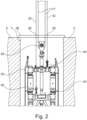
- FIG. 2 an upper end of a modified implement 20 is shown with a total of two measuring devices 40, with a milling frame 24 already being inserted into a floor 5 to form a hole 7 or slot.
- the two measuring devices 40 are attached to the milling frame 24 in a horizontally and vertically offset manner. From each measuring device 40, a measuring cable 32 extends upwards through a guide frame 36, which is placed on the surface of the ground above the hole 7. The measuring cables 32 are each guided through a predetermined fixed point 38 on the guide frame 36, which serve as a reference point for the position measurement and in particular the measurement of the verticality of the working device 20 in the ground 5.
- the measuring cables 32 extend exactly vertically to the vertical measuring axis through the respective fixed point 38. If a positional deviation occurs in the horizontal direction, this results in a deflection of at least one of the measuring cables 32 relative to the vertical measuring axis. This deviation or angulation can be determined by the measuring device 40, as follows with reference to the illustration Fig. 3 is explained in more detail. A vertical adjustment of the working device 20 takes place via the support cables 17, which are connected to the working device 20 via a suspension device 28.
- FIG. 3 A preferred embodiment of a measuring arrangement 30 according to the invention with a measuring device 40 is shown schematically in Fig. 3 shown.
- a measuring cable 32 is guided via a fastening sleeve 34 to an approximately spherical measuring device 40, which can determine a deviation and in particular an inclination of the measuring cable 32 relative to a vertical measuring axis with a high measuring accuracy.
- the Vertical measuring axis can result in particular from the direction of gravity.
- the measuring device 40 is connected to the working device 20 via a connecting device 50.
- the connecting device 50 has a connecting tube 52 extending in the vertical direction.
- the connecting pipe 52 includes a corrugated wall area and can be referred to as a corrugated pipe.
- a pull rope can extend within and along the connecting tube 52.
- the connecting tube 52 can preferably be filled with liquid.
- the connecting pipe 52 is firmly connected to the measuring device 40 via an upper fastening flange 55.
- the connecting tube 52 is attached to a pivot bearing 60 via a lower fastening flange 56, with which the connecting tube can be rotated about the vertical axis.
- a rotary drive 62 is provided below the pivot bearing 60, with which the connecting pipe 52 can be adjusted in defined positioning angles relative to the implement 20.
- the rotary drive 62 is connected to the implement 20 via a flange connection, the connection being provided either on the frame of the implement 20 or on the suspension device 28.
Description
Die Erfindung betrifft eine Messanordnung mit mindestens einem Messseil, welches einerseits mit dem vertikal verstellbaren Arbeitsgerät verbunden ist und sich andererseits zu einem oberen Festpunkt erstreckt, mindestens einer Messeinrichtung, welche mit einem zugehörigen Messseil verbunden ist und zum Messen eines Neigungswinkels des Messseils gegenüber einer vertikalen Messachse ausgebildet ist und in einem Verbindungsbereich zwischen dem Messseil und dem Arbeitsgerät angeordnet ist, und mindestens einer Verbindungseinrichtung, welche zwischen der Messeinrichtung und dem Arbeitsgerät angeordnet und ausgebildet ist, die Messeinrichtung drehfest um die vertikale Messachse und zugleich anwinkelbar zu der vertikalen Messachse an dem Arbeitsgerät zu halten, gemäß dem Oberbegriff des Anspruchs 1.The invention relates to a measuring arrangement with at least one measuring cable, which on the one hand is connected to the vertically adjustable working device and on the other hand extends to an upper fixed point, at least one measuring device, which is connected to an associated measuring cable and for measuring an angle of inclination of the measuring cable relative to a vertical measuring axis is designed and is arranged in a connection area between the measuring cable and the working device, and at least one connecting device, which is arranged and designed between the measuring device and the working device, the measuring device is non-rotatable about the vertical measuring axis and at the same time can be angled to the vertical measuring axis on the working device hold, according to the preamble of claim 1.
Die Erfindung betrifft weiterhin eine Abtragsvorrichtung zum Erstellen eines Lochs, insbesondere eines Schlitzes, im Boden, mit einem Arbeitsgerät, welches mindestens ein Abtragswerkzeug zum Abtragen von Boden aufweist, einem Trägergerät, an welchem das Abtragsgerät vertikal verstellbar zum Einbringen in den Boden gelagert ist, und einer Messanordnung zum Messen der Position, insbesondere einer Vertikalität, des Arbeitsgerätes im Boden, gemäß dem Oberbegriff des Anspruchs 10.The invention further relates to a removal device for creating a hole, in particular a slot, in the ground, with a working device which has at least one removal tool for removing soil, a carrier device on which the removal device is mounted in a vertically adjustable manner for insertion into the ground, and a measuring arrangement for measuring the position, in particular a verticality, of the implement in the ground, according to the preamble of
Beim Erstellen eines Schlitzes im Boden können aufgrund verschiedener Einflussfaktoren Abweichungen von einer gewünschten vertikalen Ausrichtung oder Lage des Schlitzes auftreten. Eine exakte positionsgenaue Erstellung eines Schlitzes im Boden ist beispielsweise bei der Erstellung einer Schlitzwand von wesentlicher Bedeutung, wie diese etwa zur Abdichtung von tiefen Baugruben gegenüber anstehendem Grundwasser benötigt wird. Eine derartige Schlitzwand wird aus einer Vielzahl von einzelnen Schlitzen, welche mit einer abbindbaren Masse verfüllt werden, hergestellt. Dabei ist es erforderlich, die einzelnen Schlitzwandsegmente exakt nebeneinander zu erstellen, so dass keine Lücken und damit Undichtigkeiten zwischen den Schlitzwandsegmenten auftreten.When creating a slot in the ground, deviations from a desired vertical orientation or position of the slot may occur due to various influencing factors. An exact positioning of a slot in the ground is essential, for example when creating a diaphragm wall. such as this is needed to seal deep excavation pits from groundwater. Such a slot wall is made from a large number of individual slots, which are filled with a settable mass. It is necessary to create the individual diaphragm wall segments exactly next to each other so that there are no gaps and thus leaks between the diaphragm wall segments.
Ein sehr genaues Verfahren zum Vermessen eines Bohrloches im Boden mittels mindestens eines Messseiles, welches sich von einem Messkörper bis zu einem Trägergerät erstreckt, ist aus der
Eine gattungsgemäße Messanordnung geht aus der
In der
Der Erfindung liegt die Aufgabe zugrunde, eine Messanordnung und eine Abtragsvorrichtung mit einer solchen Messanordnung anzugeben, mit welchen bei einem robusten Aufbau eine besonders zuverlässige und exakte Messung ermöglicht werden.The invention is based on the object of specifying a measuring arrangement and a removal device with such a measuring arrangement, with which a particularly reliable and precise measurement is made possible with a robust structure.
Die Aufgabe wird durch eine Messanordnung mit den Merkmalen des Anspruchs 1 und eine Abtragsvorrichtung mit den Merkmalen des Anspruchs 10 gelöst. Bevorzugte Ausführungsformen der Erfindung sind in den abhängigen Ansprüchen angegeben.The task is solved by a measuring arrangement with the features of claim 1 and a removal device with the features of
Die erfindungsgemäße Messanordnung ist dadurch gekennzeichnet, dass die Verbindungseinrichtung ein Verbindungsrohr aufweist, welches koaxial zur vertikalen Messachse angeordnet ist, und dass das Verbindungsrohr drehsteif um die vertikale Messachse und auslenkbar zur vertikalen Messachse ausgebildet ist.The measuring arrangement according to the invention is characterized in that the connecting device has a connecting tube which is arranged coaxially to the vertical measuring axis, and in that the connecting tube is designed to be torsionally rigid about the vertical measuring axis and deflectable relative to the vertical measuring axis.
Eine Grundidee der Erfindung liegt darin, zum Verbinden der Messeinrichtung mit dem Arbeitsgerät ein Verbindungsrohr vorzusehen, welches einerseits drehsteif um die Rohrachse, welche mit der Messachse zusammenfällt, und andererseits auslenkbar oder biegbar zur Rohrachse ist. Die Verwendung eines derartigen Verbindungsrohres bietet in mehrfacher Hinsicht Vorteile. Anders als bei einem Kardangelenk mit sich kreuzenden Schwenkachsen hat das Verbindungsrohr über seinen gesamten Umfang ein gleiches Auslenkverhalten. Zudem ist ein Verbindungsrohr als ein Gelenkelement einfach und zugleich robust aufgrund des grundsätzlich einstückigen Aufbaus. Es ist insbesondere weniger empfindlich gegenüber äußeren Einflüssen und bedarf eines erheblich geringeren Wartungs- und Reinigungsaufwandes gegenüber einem mehrteiligen Kardangelenk oder einem Kugelgelenk, insbesondere wenn ein Kontakt mit einer abbindenden Suspension oder mit Schmutzpartikeln zu erwarten ist. Die erfindungsgemäße Messanordnung ist somit insbesondere für einen rauen Arbeitseinsatz an Baustellen oder in sonstigen Außenbereichen geeignet.A basic idea of the invention is to provide a connecting tube for connecting the measuring device to the working device, which on the one hand is torsionally rigid about the tube axis, which coincides with the measuring axis, and on the other hand is deflectable or bendable to the tube axis. The use of such a connecting pipe offers advantages in several respects. Unlike a cardan joint with intersecting pivot axes, the connecting tube has the same deflection behavior over its entire circumference. In addition, a connecting pipe as a joint element is simple and at the same time robust due to the fundamentally one-piece structure. In particular, it is less sensitive to external influences and requires significantly less maintenance and cleaning effort than a multi-part cardan joint or a ball joint, especially if contact with a setting suspension or with dirt particles is expected. The measuring arrangement according to the invention is therefore particularly suitable for rough work on construction sites or in other outdoor areas.
Grundsätzlich kann das Verbindungsrohr aus jedem geeigneten Material sein, welches um die Rohrachse hinreichend drehsteif ist und eine gewünschte Auslenkbarkeit quer zur Rohrachse erlaubt. Besonders bevorzugt ist es nach einer Ausführungsform der Erfindung, dass das Verbindungsrohr schlauchartig aus einem flexiblen Material gebildet ist. Insbesondere ist ein Kunststoffmaterial, insbesondere ein elastisches Kunststoffmaterial zum Bilden des Verbindungsrohrs geeignet.In principle, the connecting pipe can be made of any suitable material that is sufficiently torsionally rigid around the pipe axis and allows the desired deflection transversely to the pipe axis. According to one embodiment, it is particularly preferred Invention that the connecting pipe is formed like a hose from a flexible material. In particular, a plastic material, in particular an elastic plastic material, is suitable for forming the connecting tube.
Eine Verbesserung der Auslenkbarkeit und damit der Empfindlichkeit der Messanordnung wird nach einer Ausführungsvariante der Erfindung dadurch erzielt, dass das Verbindungsrohr zumindest abschnittsweise als ein Wellrohr mit einem gewellten Wandbereich ausgebildet ist. Das Verbindungsrohr weist somit mindestens einen Bereich mit sich ändernden Durchmessern, insbesondre ansteigenden und abfallenden Durchmessern auf. Vorzugsweise kann auch das Rohr insgesamt als ein Wellrohr ausgebildet sein. Dabei ist bevorzugt, das Wellrohr aus einem metallischen Material, z. B. Stahl oder Edelstahl zu fertigenAccording to an embodiment variant of the invention, an improvement in the deflection and thus the sensitivity of the measuring arrangement is achieved in that the connecting pipe is designed, at least in sections, as a corrugated pipe with a corrugated wall region. The connecting pipe therefore has at least one area with changing diameters, in particular increasing and decreasing diameters. Preferably, the tube as a whole can also be designed as a corrugated tube. It is preferred that the corrugated tube is made of a metallic material, e.g. B. steel or stainless steel
Eine Erhöhung der axialen Steifigkeit des Verbindungsrohrs bei einer gleichzeitig weiter empfindlichen Anwinkelbarkeit des Rohres kann nach einer weiteren bevorzugten Ausführungsform der Erfindung dadurch erreicht werden, dass das Verbindungsrohr mit einer inkompressiblen Flüssigkeit gefüllt ist. Vorzugsweise kann als Flüssigkeit ein Öl oder Wasser vorgesehen werden.According to a further preferred embodiment of the invention, an increase in the axial rigidity of the connecting tube while at the same time allowing the tube to be angled more sensitively can be achieved in that the connecting tube is filled with an incompressible liquid. An oil or water can preferably be provided as the liquid.
Eine weitere bevorzugte Ausführungsform der Erfindung besteht darin, dass an dem zum Arbeitsgerät gerichteten Ende des Verbindungsrohres ein Drehlager vorgesehen ist, mit welchem das Verbindungsrohr um die vertikale Messachse drehbar ist, insbesondere um einen Winkel von 180°. Grundsätzlich kann das Drehlager an einer beliebigen Stelle des Verbindungsrohrs angeordnet sein. Durch die Drehbarkeit des Verbindungsrohres um die Mess- oder Rohrachse kann eine Messgenauigkeit noch weiter erhöht werden.A further preferred embodiment of the invention is that a pivot bearing is provided at the end of the connecting tube directed towards the working device, with which the connecting tube can be rotated about the vertical measuring axis, in particular through an angle of 180°. In principle, the pivot bearing can be arranged at any point on the connecting pipe. By rotating the connecting pipe around the measuring or pipe axis, measuring accuracy can be increased even further.
Insbesondere kann dies dadurch erreicht werden, dass ein Drehantrieb zum Verdrehen des drehbar gelagerten Verbindungsrohres in mindestens eine unterschiedliche Position angeordnet ist und dass die Messeinrichtung zum Messen des Neigungswinkels in den unterschiedlichen Drehpositionen ausgebildet ist. Insbesondere kann mit dem Drehantrieb das Verbindungsrohr nach einer Messung in einer ersten Position in eine zweite Position, welche um 90° oder um 180° zu der ersten Position versetzt ist, verstellt werden. In dieser zweiten Position kann eine weitere Messung vorgenommen werden. Hierdurch ist eine sogenannte Umschlagsmessung möglich, mit welcher Messfehler kompensiert oder auf ein Mindestmaß reduziert werden können. Grundsätzlich kann eine Messung auch in mehr als zwei unterschiedlichen Drehpositionen des Verbindungsrohrs durchgeführt werden.In particular, this can be achieved in that a rotary drive is arranged for rotating the rotatably mounted connecting tube into at least one different position and in that the measuring device is designed to measure the angle of inclination in the different rotational positions. In particular, the connecting pipe can be adjusted with the rotary drive after a measurement in a first position into a second position, which is offset by 90° or 180° to the first position. In this second position, another measurement can be made. This makes a so-called envelope measurement possible, with which Measuring errors can be compensated for or reduced to a minimum. In principle, a measurement can also be carried out in more than two different rotational positions of the connecting pipe.
Generell ist die Messanordnung mit bereits einem Messseil für bestimmte Einsatzzwecke verwendbar. Besonders vorteilhaft ist es nach einer Weiterbildung der Erfindung, dass mindestens zwei Messseile vorgesehen sind, welche horizontal beabstandet zueinander an dem Arbeitsgerät angebracht sind. Vorzugsweise verlaufen die mindestens zwei Messseile in einer Normalposition parallel zueinander. Durch die Anordnung von mindestens zwei Messseilen kann auch eine Verdrehung des Arbeitsgerätes im Raum festgestellt werden, wobei an jedem Messseil eine eigene Winkelmessung vorgenommen wird. Es können auch drei oder mehr Messseile vorgesehen sein, welche sich zwischen dem Arbeitsgerät und einem jeweiligen Festpunkt erstrecken. Für eine exakte Messung müssen sich die Messseile in einem gespannten Zustand befinden, wobei hierzu eine Spanneinrichtung vorzusehen ist. Bei der Anordnung von nur einem Messseil kann eine Verdrehung über eine geeignete Detektionseinrichtung erfasst werden, beispielsweise mit einem Gyroskop.In general, the measuring arrangement can be used with a measuring cable for certain purposes. According to a further development of the invention, it is particularly advantageous that at least two measuring cables are provided, which are attached to the implement at a horizontal distance from one another. Preferably, the at least two measuring cables run parallel to one another in a normal position. By arranging at least two measuring cables, rotation of the implement in space can also be determined, with a separate angle measurement being carried out on each measuring cable. Three or more measuring cables can also be provided, which extend between the implement and a respective fixed point. For an exact measurement, the measuring cables must be in a tensioned state, and a tensioning device must be provided for this purpose. When only one measuring cable is arranged, twisting can be detected using a suitable detection device, for example a gyroscope.
Eine besonders gute axiale Befestigung des Messseils an dem Arbeitsgerät über die Verbindungseinrichtung kann dadurch erzielt werden, dass innerhalb des Verbindungsrohrs ein Zugelement angeordnet ist. Insbesondere kann das Zugelement ein Zugseil sein, welches weiter eine hinreichende Auslenkung des Verbindungsrohres quer zur vertikalen Messachse ermöglicht.A particularly good axial attachment of the measuring cable to the implement via the connecting device can be achieved by arranging a tension element within the connecting tube. In particular, the tension element can be a traction cable, which further enables sufficient deflection of the connecting tube transversely to the vertical measuring axis.
Die Erfindung umfasst weiter eine Abtragsvorrichtung zum Erstellen eines Lochs, insbesondere eines Schlitzes im Boden, mit einem Arbeitsgerät, welches mindestens ein Abtragswerkzeug zum Abtragen von Boden aufweist, einem Trägergerät, an welchem das Arbeitsgerät vertikal verstellbar zum Einbringen in den Boden gelagert ist, wobei eine erfindungsgemäße Messanordnung zum Messen der Position, insbesondere der Vertikallität, des Arbeitsgerätes im Boden angeordnet ist. Durch den Einsatz der erfindungsgemäßen Messanordnung an der Abtragsvorrichtung können damit die zuvor beschriebenen Vorteile erzielt werden.The invention further comprises a removal device for creating a hole, in particular a slot in the ground, with a working device which has at least one removal tool for removing soil, a carrier device on which the working device is mounted in a vertically adjustable manner for insertion into the ground, wherein a Measuring arrangement according to the invention for measuring the position, in particular the verticality, of the implement is arranged in the ground. By using the measuring arrangement according to the invention on the removal device, the advantages described above can be achieved.
Das Arbeitsgerät kann ein Gerät für den Spezialtiefbau sein und insbesondere eine Schlitzwandfräse, ein Schlitzwandgreifer oder auch ein Imlochbohrgerät oder ein Bohrwerkzeug umfassen. Das Trägergerät ist insbesondere eine Baumaschine mit einem fahrbaren Unterwagen, auf welchem ein drehbarer Oberwagen gelagert ist. Der Unterwagen kann insbesondere ein Raupenfahrwerk umfassen.The working device can be a device for special foundation engineering and can in particular include a trench wall cutter, a trench wall grab or even an in-hole drilling device or a drilling tool. The carrier device is in particular a construction machine with a mobile undercarriage on which a rotatable superstructure is mounted. The undercarriage can in particular include a crawler chassis.
Eine besonders bevorzugte Ausführungsform der erfindungsgemäßen Abtragsvorrichtung besteht darin, dass das Messseil eine Dichte aufweist, welche gleich oder geringer als die Dichte einer Stützflüssigkeit ist, mit welcher das durch das Arbeitsgerät erstellte Loch gefüllt ist. Insbesondere bei einer gleichen Dichte zu einer Stützflüssigkeit an ihrer Oberfläche in dem Loch können unerwünschte Einwirkungen aufgrund von Dichteunterschieden auf das Seil vermieden werden. Dies erhöht eine Reproduzierbarkeit des Messergebnisses. Die Dichte der Suspension kann gleichbleibend sein oder sich abhängig von der Tiefe ändern.A particularly preferred embodiment of the removal device according to the invention is that the measuring cable has a density which is equal to or lower than the density of a supporting liquid with which the hole created by the working device is filled. In particular, if the density of a supporting liquid on its surface in the hole is the same, undesirable effects on the rope due to differences in density can be avoided. This increases the reproducibility of the measurement result. The density of the suspension can be constant or change depending on the depth.
Bei der Abtragsvorrichtung kann eine Messung durch die Messanordnung kontinuierlich oder zu vorgegebenen Zeitpunkten erfolgen. Abhängig von den ermittelten Messwerten kann eine Abweichung der Position des Arbeitsgerätes in dem Loch frühzeitig festgestellt werden. Grundsätzlich kann das Arbeitsgerät dann von Hand nachgesteuert werden.In the case of the removal device, a measurement can be carried out by the measuring arrangement continuously or at predetermined times. Depending on the measured values determined, a deviation in the position of the implement in the hole can be detected at an early stage. In principle, the implement can then be re-controlled by hand.
Besonders bevorzugt ist es nach einer Weiterbildung der Erfindung, dass das Arbeitsgerät mit ansteuerbaren Stellorganen zur Positionsänderung des Arbeitsgerätes im Loch versehen ist und dass an dem Steuergerät eine Steuer- und Auswerteeinheit vorgesehen und ausgebildet ist, abhängig von den Messwerten der mindestens einen Messeinrichtung eine Position des Arbeitsgerätes zu kontrollieren und durch Ansteuern der Stellorgane zu ändern. Insbesondere kann hierdurch eine automatische Steuerung oder Regelung der Position des Arbeitsgerätes im Boden erfolgen. Hierdurch können in einfacher Weise positionsgenaue Löcher und insbesondere Schlitze im Boden erstellt werden. Dies ermöglicht es, einen grundsätzlich üblichen Überschnitt zwischen den aneinander angrenzenden Schlitzwandsegmenten sehr gering zu halten, so dass sich bei der Erstellung einer Schlitz- oder Dichtwand eine erhebliche Ersparnis an Material und Verschleiß an den Abtragswerkzeugen ergibt.According to a further development of the invention, it is particularly preferred that the working device is provided with controllable actuating elements for changing the position of the working device in the hole and that a control and evaluation unit is provided and designed on the control device, depending on the measured values of the at least one measuring device, a position of the Control the working device and change it by controlling the actuators. In particular, this allows automatic control or regulation of the position of the implement in the ground. This makes it easy to create precisely positioned holes and, in particular, slots in the floor. This makes it possible to keep a generally usual overcut between the adjacent diaphragm wall segments very small, so that when creating a diaphragm or sealing wall there is a significant saving in material and wear on the removal tools.
Eine besonders vorteilhafte Abtragsvorrichtung wird nach einer Weiterbildung der Erfindung dadurch erzielt, dass an dem Trägergerät eine Winde für jedes Messseil vorgesehen ist, durch welche das Messseil unter einer vorgebbaren Vorspannung dem Arbeitsgerät nachführbar ist. Die Vorspannung kann dabei insbesondere so eingestellt werden, dass das Messseil stets vollständig gespannt ist, wobei jedoch weiter eine sensible Auslenkung des Messseiles und damit eine hohe Messgenauigkeit gegeben sind. Dies kann durch Einstellung eines entsprechenden Anzugsdrehmoments an einem Windenantrieb für die Winde erreicht werden.According to a further development of the invention, a particularly advantageous removal device is achieved in that a winch is provided on the carrier device for each measuring cable, through which the measuring cable can be tracked to the working device under a predeterminable pretension. The pretension can in particular be adjusted so that the measuring cable is always completely tensioned, although a sensitive deflection of the measuring cable and thus a high measurement accuracy are still ensured. This can be achieved by setting an appropriate tightening torque on a winch drive for the winch.
Grundsätzlich kann der mindestens eine Festpunkt an jeder geeigneten Stelle vorgesehen sein, welcher eine zuverlässige und dauerhafte Festlegung des Messseiles erlaubt. Besonders zweckmäßig ist es insbesondere, dass der mindestens eine Festpunkt an einem Leitrahmen ausgebildet und eingemessen ist, welcher an einem oberen Ende des Lochs angeordnet ist. Insbesondere bei der Erstellung einer Schlitzwand wird ein Führungsgraben mit betonierten Wänden entlang einer Bodenoberfläche erstellt. Entlang diesem Führungsgraben kann ein Leitrahmen, vorzugsweise aus Metall, angeordnet und befestigt werden. An diesem Leitrahmen können durch entsprechende Halteeinrichtungen Festpunkte für das Messseil festgelegt werden. Insbesondere kann hierfür eine Messhülse und/oder eine Umlenkrolle am Leitrahmen angeordnet sein, durch welche beziehungsweise über welche passend das Messseil geführt ist. Der Festpunkt kann insbesondere für eine besonders exakte Messung eingemessen sein, so dass beispielsweise eine eindeutige Lagedefinition in einem Baustellenkoordinatensystem gegeben ist.In principle, the at least one fixed point can be provided at any suitable location, which allows the measuring cable to be fixed reliably and permanently. It is particularly expedient that the at least one fixed point is formed and measured on a guide frame, which is arranged at an upper end of the hole. In particular, when creating a diaphragm wall, a guide trench with concrete walls is created along a ground surface. A guide frame, preferably made of metal, can be arranged and fastened along this guide trench. Fixed points for the measuring cable can be set on this guide frame using appropriate holding devices. In particular, a measuring sleeve and/or a deflection roller can be arranged on the guide frame for this purpose, through which or over which the measuring cable is guided. The fixed point can be calibrated in particular for a particularly precise measurement, so that, for example, a clear position definition is given in a construction site coordinate system.
Grundsätzlich kann das Arbeitsgerät der Abtragsvorrichtung jedes beliebige Baugerät zur Erstellung eines Lochs im Boden sein. Besonders vorteilhaft ist es nach einer Weiterbildung der Erfindung, dass das Arbeitsgerät eine Schlitzwandfräse mit mindestens einem angetriebenen Fräsrad ist, welches an einem unteren Ende eines Fräsenrahmens drehbar um eine horizontale Drehachse gelagert ist. Insbesondere können zwei Paare von Fräsrädern horizontal zueinander versetzt an der Unterseite des Fräsenrahmens angeordnet sein.In principle, the tool of the removal device can be any construction device for creating a hole in the ground. According to a further development of the invention, it is particularly advantageous that the working device is a trench wall cutter with at least one driven cutting wheel, which is rotatably mounted about a horizontal axis of rotation at a lower end of a cutter frame. In particular, two pairs of milling wheels can be arranged horizontally offset from one another on the underside of the milling frame.
Die Erfindung wird nachfolgend anhand von bevorzugten Ausführungsbeispielen weiter beschrieben, welche schematisch in den Zeichnungen dargestellt sind. In den Zeichnungen zeigen:
- Fig. 1
- eine perspektivische Ansicht einer Abtragsvorrichtung mit einer erfindungsgemäßen Messanordnung;
- Fig. 2
- eine Detailansicht zu der Messanordnung von
Fig. 1 in einer Vorderansicht; und - Fig. 3
- eine vergrößerte Detailansicht zu einer Messeinrichtung einer erfindungsgemäßen Messanordnung.
- Fig. 1
- a perspective view of a removal device with a measuring arrangement according to the invention;
- Fig. 2
- a detailed view of the measuring arrangement
Fig. 1 in a front view; and - Fig. 3
- an enlarged detailed view of a measuring device of a measuring arrangement according to the invention.
Gemäß
In dem dargestellten Ausführungsbeispiel ist das Arbeitsgerät 20 als eine Schlitzwandfräse 22 mit einem Fräsenrahmen 24 ausgebildet. An dem Fräsenrahmen 24 ist eine Vielzahl von ausstellbaren klappenförmigen Stellorganen 25 angeordnet, mit welchen in bekannter Weise eine Lage der Schlitzwandfräse 22 in einem Loch im Boden verändert und eingestellt werden kann. An einem unteren Ende des Fräsenrahmens 24 sind als Abtragswerkzeuge 26 zwei Paare von Fräsrädern 27 drehbar gelagert. In bekannter Weise können die Fräsräder 27 über einen inneren Fräsradantrieb zum Abtragen von Bodenmaterial in Drehung versetzt werden.In the exemplary embodiment shown, the working
Zum Messen einer Position, insbesondere einer Vertikalität des Arbeitsgerätes 20 im Boden ist im Bereich einer Aufhängeeinrichtung 28, über welche die Schlitzwandfräse 22 mit den Tragseilen 17 verbunden ist, eine Messeinrichtung 40 einer erfindungsgemäßen Messanordnung 30 angebracht. Die Messeinrichtung 40, welche nachfolgend näher beschrieben wird, ist dabei etwa mittig und koaxial zur Längsachse des Arbeitsgerätes 20 angeordnet. Von der Messeinrichtung 40, welche fest mit dem Arbeitsgerät 20 verbunden ist, erstreckt sich ein Messseil 32 nach oben zu einem definierten Festpunkt 38, welcher an einem Leitrahmen 36 ausgebildet ist. Der Leitrahmen 36 wird am oberen Ende des Lochs an der Bodenoberfläche befestigt, wobei der Festpunkt 38 eingemessen ist und einen Soll-Bezugspunkt für die Lage des Arbeitsgerätes 20 vorgibt.To measure a position, in particular a verticality, of the working
Das Messseil 32 erstreckt sich über den Leitrahmen 36 nach hoch oben hinaus zu dem Trägergerät 12, wobei das Messseil 32 über Umlenkrollen zu einer Winde 18 am Oberwagen 14 geführt ist. Über die Winde 18 können das Messseil 32 dem sich in den Boden absenkenden Arbeitsgerät 20 nachgeführt und eine gewisse Spannung des Messeiles 32 sichergestellt werden.The measuring
In grundsätzlich bekannter Weise werden von dem Trägergerät 12 über entsprechende Winden und Trommeln weitere Leitungen und Schläuche zum Betrieb der Schlitzwandfräse 22 nachgeführt.In a generally known manner, additional lines and hoses for operating the
In
Die beiden Messeinrichtungen 40 sind dabei horizontal und vertikal versetzt an dem Fräsenrahmen 24 befestigt. Von jeder Messeinrichtung 40 erstreckt sich ein Messseil 32 nach oben durch einen Leitrahmen 36, welcher an der Oberfläche des Bodens über dem Loch 7 aufgesetzt ist. Die Messseile 32 sind dabei jeweils durch einen vorgegebenen Festpunkt 38 am Leitrahmen 36 geführt, welche als ein Bezugspunkt für die Positionsmessung und insbesondere die Messung der Vertikalität des Arbeitsgerätes 20 im Boden 5 dienen.The two
Befindet sich das Arbeitsgerät 20 in der Sollposition, erstrecken sich die Messseile 32 exakt vertikal zur vertikalen Messachse durch den jeweiligen Festpunkt 38 hindurch. Tritt eine Lageabweichung in horizontaler Richtung auf, ergibt sich eine Ablenkung zumindest eines der Messseile 32 gegenüber der vertikalen Messachse. Diese Abweichung oder Anwinkelung kann durch die Messeinrichtung 40 bestimmt werden, wie nachfolgend unter Bezug auf die Darstellung nach
Eine bevorzugte Ausführungsform einer erfindungsgemäßen Messanordnung 30 mit einer Messeinrichtung 40 ist schematisch in
Die Messeinrichtung 40 ist über eine Verbindungseinrichtung 50 mit dem Arbeitsgerät 20 verbunden. Die Verbindungseinrichtung 50 weist ein sich in vertikaler Richtung erstreckendes Verbindungsrohr 52 auf. Das Verbindungsrohr 52 umfasst einen gewellten Wandbereich und kann als Wellrohr bezeichnet werden. Innerhalb und entlang des Verbindungsrohrs 52 kann sich ein Zugseil erstrecken. Das Verbindungsrohr 52 kann vorzugsweise mit Flüssigkeit gefüllt sein. Über einen oberen Befestigungsflansch 55 ist das Verbindungsrohr 52 fest mit der Messeinrichtung 40 verbunden. Über einen unteren Befestigungsflansch 56 ist das Verbindungsrohr 52 an einem Drehlager 60 angebracht, mit welchem das Verbindungsrohr um die Vertikalachse gedreht werden kann. Zum Verdrehen ist unterhalb des Drehlagers 60 ein Drehantrieb 62 vorgesehen, mit welchem das Verbindungsrohr 52 gegenüber dem Arbeitsgerät 20 in definierten Stellwinkeln verstellbar ist. Auf diese Weise kann eine Messung des Neigungswinkels in verschiedenen Drehpositionen erfolgen, so dass hierdurch auch eine Bestimmung der Lage des Arbeitsgerätes 20 im Raum ermöglicht wird. Der Drehantrieb 62 ist über eine Flanschverbindung mit dem Arbeitsgerät 20 verbunden, wobei die Verbindung entweder am Rahmen des Arbeitsgerätes 20 oder an der Aufhängeeinrichtung 28 vorgesehen ist.The measuring
Claims (15)
- Measuring arrangement for measuring a position, in particular a verticality, of a vertically adjustable and lowerable working apparatus (20) with respect to an upper fixed point (38), with- at least one measuring cable (32) which is on the one hand connected to the vertically adjustable working apparatus (20) and on the other hand extends towards the fixed point (38),- at least one measuring means (40) which is connected to the corresponding measuring cable (32) and designed to measure an angle of inclination of the measuring cable (32) relative to a vertical measurement axis and is arranged in a connection region between the measuring cable (32) and the working apparatus (20), and- at least one connecting means (50) which is arranged between the measuring means (40) and the working apparatus (20) and is designed to keep the measuring means (40) torque proof about the vertical measurement axis and at the same time capable of being angled with respect to the vertical measurement axis on the working apparatus (20),
characterized in that- the connecting means (50) has a connecting tube (52) which is arranged coaxially to the vertical measurement axis, and- in that the connecting tube (52) is designed so as to be torsion proof about the vertical measurement axis and deflectable with respect to the vertical measurement axis. - Measuring arrangement according to claim 1,
characterized in that
the connecting tube (52) is formed in a hose-like manner from a flexible material. - Measuring arrangement according to claim 1 or 2,
characterized in that
the connecting tube (52) is at least in sections designed as a corrugated tube with a corrugated wall region (54). - Measuring arrangement according to claim 3,
characterized in that
the corrugated tube is manufactured from metal, in particular steel. - Measuring arrangement according to any one of claims 1 to 4,
characterized in that
the connecting tube (52) is filled with an incompressible liquid. - Measuring arrangement according to any one of claims 1 to 5,
characterized in that
at the end of the connecting tube (52) which is directed towards the working apparatus (20) a rotary bearing (60) is provided, with which the connecting tube (52) is rotatable about the vertical measurement axis, in particular about an angle of 180°. - Measuring arrangement according to claim 6,
characterized in thata rotary drive (62) is arranged for rotating the rotatably supported connecting tube (52) in at least one different rotational position andin that the measuring means (40) is designed to measure the angle of inclination in the different rotational positions. - Measuring arrangement according to any one of claims 1 to 7,
characterized in that
at least two measuring cables (32) are provided which are attached to the working apparatus (20) by being horizontally spaced apart from each other. - Measuring arrangement according to any one of claims 1 to 8,
characterized in that
inside the connecting tube (52) a pull element, in particular a pull cable, is arranged. - Removal device for producing a hole (7), in particular a trench, in the ground (5), with- a working apparatus (20) which has at least one removal tool (26) for removing ground (5),- a carrier implement (12), on which the working apparatus (20) is supported in a vertically adjustable manner for introduction into the ground (5), and- a measuring arrangement (30) for measuring the position, in particular a verticality, of the working apparatus (20) in the ground (5),characterized in that
a measuring arrangement (30) according to any one of claims 1 to 8 is arranged. - Removal device according to claim 10,
characterized in that
the measuring cable (32) has a density which is equal to or lower than the density of a slurry, with which the hole (7) produced by the working apparatus (20) is filled. - Removal device according to claim 10 or 11,
characterized in thatthe working apparatus (20) is provided with actuatable positioning members (25) for change of position of the working apparatus (20) in the hole (7) andin that on the carrier implement (12) a control and evaluation unit is provided and designed to check a position of the working apparatus (20) and to change this by actuating the positioning members (25) depending on the measured values of the at least one measuring means (40). - Removal device according to any one of claims 10 to 12,
characterized in that
on the carrier implement (12) a winch (18) is provided for each measuring cable (32), by which the measuring cable (32) can be tracked to the working apparatus whilst being under predeterminable pretension. - Removal device according to any one of claims 10 to 13,
characterized in that
the at least one fixed point (38) is designed and calibrated on a lead frame (36) which is arranged at an upper end of the hole (7). - Removal device according to any one of claims 10 to 14,
characterized in that
the working apparatus (20) is a diaphragm wall cutter (22) with at least one driven cutting wheel (27) which is rotatably supported about a horizontal axis of rotation on a lower end of a cutter frame (24).
Priority Applications (5)
| Application Number | Priority Date | Filing Date | Title |
|---|---|---|---|
| EP21164313.5A EP4063568B1 (en) | 2021-03-23 | 2021-03-23 | Measurement assembly and erosion device with a measurement assembly |
| CN202280015333.4A CN116888327A (en) | 2021-03-23 | 2022-03-11 | Measuring assembly and removal device with measuring assembly |
| KR1020237026033A KR20230125824A (en) | 2021-03-23 | 2022-03-11 | Measuring device and removal device with measuring device |
| JP2023558183A JP2024511426A (en) | 2021-03-23 | 2022-03-11 | Measuring device and removal device with measuring device |
| PCT/EP2022/056289 WO2022200074A1 (en) | 2021-03-23 | 2022-03-11 | Measuring assembly and removal device comprising a measuring assembly |
Applications Claiming Priority (1)
| Application Number | Priority Date | Filing Date | Title |
|---|---|---|---|
| EP21164313.5A EP4063568B1 (en) | 2021-03-23 | 2021-03-23 | Measurement assembly and erosion device with a measurement assembly |
Publications (3)
| Publication Number | Publication Date |
|---|---|
| EP4063568A1 EP4063568A1 (en) | 2022-09-28 |
| EP4063568C0 EP4063568C0 (en) | 2023-10-04 |
| EP4063568B1 true EP4063568B1 (en) | 2023-10-04 |
Family
ID=75203014
Family Applications (1)
| Application Number | Title | Priority Date | Filing Date |
|---|---|---|---|
| EP21164313.5A Active EP4063568B1 (en) | 2021-03-23 | 2021-03-23 | Measurement assembly and erosion device with a measurement assembly |
Country Status (5)
| Country | Link |
|---|---|
| EP (1) | EP4063568B1 (en) |
| JP (1) | JP2024511426A (en) |
| KR (1) | KR20230125824A (en) |
| CN (1) | CN116888327A (en) |
| WO (1) | WO2022200074A1 (en) |
Family Cites Families (4)
| Publication number | Priority date | Publication date | Assignee | Title |
|---|---|---|---|---|
| DE4119212C2 (en) * | 1991-06-11 | 1996-06-27 | Bauer Spezialtiefbau | Process for milling a diaphragm wall |
| FR2755467B1 (en) | 1996-11-06 | 1999-05-14 | Sol Comp Du | DEVICE FOR MEASURING THE VERTICALITY OF A DRILLING MACHINE |
| ES2525921T3 (en) | 2012-08-13 | 2015-01-02 | Bauer Spezialtiefbau Gmbh | Procedure and device to produce and measure a perforation |
| FR3078739B1 (en) | 2018-03-09 | 2020-03-27 | Soletanche Freyssinet | DRILLING MACHINE COMPRISING A CONNECTION DEVICE FOR A VERTICALITY MEASURING DEVICE |
-
2021
- 2021-03-23 EP EP21164313.5A patent/EP4063568B1/en active Active
-
2022
- 2022-03-11 JP JP2023558183A patent/JP2024511426A/en active Pending
- 2022-03-11 CN CN202280015333.4A patent/CN116888327A/en active Pending
- 2022-03-11 WO PCT/EP2022/056289 patent/WO2022200074A1/en active Application Filing
- 2022-03-11 KR KR1020237026033A patent/KR20230125824A/en unknown
Also Published As
| Publication number | Publication date |
|---|---|
| KR20230125824A (en) | 2023-08-29 |
| EP4063568C0 (en) | 2023-10-04 |
| WO2022200074A1 (en) | 2022-09-29 |
| JP2024511426A (en) | 2024-03-13 |
| EP4063568A1 (en) | 2022-09-28 |
| CN116888327A (en) | 2023-10-13 |
Similar Documents
| Publication | Publication Date | Title |
|---|---|---|
| EP3081737B1 (en) | Drilling apparatus for making a borehole with pipe and method for operating a drilling apparatus | |
| DE102007005944B4 (en) | slant drill | |
| EP0345650B1 (en) | Anchor hole drilling rig | |
| EP2623677B1 (en) | Assembly and method for manufacturing a slotted wall element | |
| EP0699888A2 (en) | Determination of the diameter or wallthickness of wall elements | |
| EP2410092B1 (en) | Device and method for manufacturing vertical walls in a foundation soil | |
| EP4063568B1 (en) | Measurement assembly and erosion device with a measurement assembly | |
| EP2698499B1 (en) | Method and device producing and measuring a borehole | |
| CH712908A2 (en) | Measurement signal evaluation method for a pipe jacking method. | |
| DE102012112411B3 (en) | Thrust boring steering device for controllably driving tubular string into ground, has conveyor worm which is led up to spray head by connecting ring of universal joint | |
| DE4132314C1 (en) | Vehicle mounted piling drill with mast - on which travels carriage with rotary head and tool duct laterally offset w.r.t.carriage guideway | |
| EP0169393A1 (en) | Device for producing boreholes at an inaccessible cross-section | |
| EP3819433B1 (en) | Soil removal device and method for creating a hole in the ground | |
| EP1790779B1 (en) | Device for cutting trenches in the ground and method for producing a trench | |
| WO2022117777A1 (en) | Sinking device for sinking a shaft in the ground, having a device for ascertaining the position of the sinking device in the ground | |
| EP3584370B1 (en) | Construction equipment and method for operating same | |
| DE3823784C2 (en) | ||
| DE4211059C1 (en) | ||
| DE19837546A1 (en) | Measuring device for determining the alignment and the course of a drill pipe | |
| EP3725955A1 (en) | Slotted wall gripper and method for creating a slot in the ground | |
| EP3879064B1 (en) | Soil working device and method for producing a essentially vertical hole in the ground | |
| EP3907371B1 (en) | Machine tool and method for processing a soil | |
| CH671607A5 (en) | ||
| EP4269699A1 (en) | Machine for use in civil engineering | |
| DE4420705A1 (en) | Automatic measurement and control of propulsion system when tunnel building |
Legal Events
| Date | Code | Title | Description |
|---|---|---|---|
| PUAI | Public reference made under article 153(3) epc to a published international application that has entered the european phase |
Free format text: ORIGINAL CODE: 0009012 |
|
| STAA | Information on the status of an ep patent application or granted ep patent |
Free format text: STATUS: THE APPLICATION HAS BEEN PUBLISHED |
|
| AK | Designated contracting states |
Kind code of ref document: A1 Designated state(s): AL AT BE BG CH CY CZ DE DK EE ES FI FR GB GR HR HU IE IS IT LI LT LU LV MC MK MT NL NO PL PT RO RS SE SI SK SM TR |
|
| STAA | Information on the status of an ep patent application or granted ep patent |
Free format text: STATUS: REQUEST FOR EXAMINATION WAS MADE |
|
| 17P | Request for examination filed |
Effective date: 20230217 |
|
| RBV | Designated contracting states (corrected) |
Designated state(s): AL AT BE BG CH CY CZ DE DK EE ES FI FR GB GR HR HU IE IS IT LI LT LU LV MC MK MT NL NO PL PT RO RS SE SI SK SM TR |
|
| GRAP | Despatch of communication of intention to grant a patent |
Free format text: ORIGINAL CODE: EPIDOSNIGR1 |
|
| STAA | Information on the status of an ep patent application or granted ep patent |
Free format text: STATUS: GRANT OF PATENT IS INTENDED |
|
| GRAJ | Information related to disapproval of communication of intention to grant by the applicant or resumption of examination proceedings by the epo deleted |
Free format text: ORIGINAL CODE: EPIDOSDIGR1 |
|
| STAA | Information on the status of an ep patent application or granted ep patent |
Free format text: STATUS: REQUEST FOR EXAMINATION WAS MADE |
|
| GRAP | Despatch of communication of intention to grant a patent |
Free format text: ORIGINAL CODE: EPIDOSNIGR1 |
|
| INTG | Intention to grant announced |
Effective date: 20230509 |
|
| STAA | Information on the status of an ep patent application or granted ep patent |
Free format text: STATUS: GRANT OF PATENT IS INTENDED |
|
| INTC | Intention to grant announced (deleted) | ||
| INTG | Intention to grant announced |
Effective date: 20230601 |
|
| GRAS | Grant fee paid |
Free format text: ORIGINAL CODE: EPIDOSNIGR3 |
|
| GRAA | (expected) grant |
Free format text: ORIGINAL CODE: 0009210 |
|
| STAA | Information on the status of an ep patent application or granted ep patent |
Free format text: STATUS: THE PATENT HAS BEEN GRANTED |
|
| AK | Designated contracting states |
Kind code of ref document: B1 Designated state(s): AL AT BE BG CH CY CZ DE DK EE ES FI FR GB GR HR HU IE IS IT LI LT LU LV MC MK MT NL NO PL PT RO RS SE SI SK SM TR |
|
| REG | Reference to a national code |
Ref country code: GB Ref legal event code: FG4D Free format text: NOT ENGLISH |
|
| REG | Reference to a national code |
Ref country code: CH Ref legal event code: EP |
|
| REG | Reference to a national code |
Ref country code: IE Ref legal event code: FG4D Free format text: LANGUAGE OF EP DOCUMENT: GERMAN |
|
| REG | Reference to a national code |
Ref country code: DE Ref legal event code: R096 Ref document number: 502021001603 Country of ref document: DE |
|
| U01 | Request for unitary effect filed |
Effective date: 20231004 |
|
| U07 | Unitary effect registered |
Designated state(s): AT BE BG DE DK EE FI FR IT LT LU LV MT NL PT SE SI Effective date: 20231018 |
|
| PG25 | Lapsed in a contracting state [announced via postgrant information from national office to epo] |
Ref country code: GR Free format text: LAPSE BECAUSE OF FAILURE TO SUBMIT A TRANSLATION OF THE DESCRIPTION OR TO PAY THE FEE WITHIN THE PRESCRIBED TIME-LIMIT Effective date: 20240105 |
|
| PG25 | Lapsed in a contracting state [announced via postgrant information from national office to epo] |
Ref country code: IS Free format text: LAPSE BECAUSE OF FAILURE TO SUBMIT A TRANSLATION OF THE DESCRIPTION OR TO PAY THE FEE WITHIN THE PRESCRIBED TIME-LIMIT Effective date: 20240204 |
|
| U20 | Renewal fee paid [unitary effect] |
Year of fee payment: 4 Effective date: 20240312 |
|
| PG25 | Lapsed in a contracting state [announced via postgrant information from national office to epo] |
Ref country code: ES Free format text: LAPSE BECAUSE OF FAILURE TO SUBMIT A TRANSLATION OF THE DESCRIPTION OR TO PAY THE FEE WITHIN THE PRESCRIBED TIME-LIMIT Effective date: 20231004 |
|
| PG25 | Lapsed in a contracting state [announced via postgrant information from national office to epo] |
Ref country code: IS Free format text: LAPSE BECAUSE OF FAILURE TO SUBMIT A TRANSLATION OF THE DESCRIPTION OR TO PAY THE FEE WITHIN THE PRESCRIBED TIME-LIMIT Effective date: 20240204 Ref country code: GR Free format text: LAPSE BECAUSE OF FAILURE TO SUBMIT A TRANSLATION OF THE DESCRIPTION OR TO PAY THE FEE WITHIN THE PRESCRIBED TIME-LIMIT Effective date: 20240105 Ref country code: ES Free format text: LAPSE BECAUSE OF FAILURE TO SUBMIT A TRANSLATION OF THE DESCRIPTION OR TO PAY THE FEE WITHIN THE PRESCRIBED TIME-LIMIT Effective date: 20231004 |