EP4063568B1 - Dispositif de mesure et dispositif d'enlèvement doté d'un dispositif de mesure - Google Patents
Dispositif de mesure et dispositif d'enlèvement doté d'un dispositif de mesure Download PDFInfo
- Publication number
- EP4063568B1 EP4063568B1 EP21164313.5A EP21164313A EP4063568B1 EP 4063568 B1 EP4063568 B1 EP 4063568B1 EP 21164313 A EP21164313 A EP 21164313A EP 4063568 B1 EP4063568 B1 EP 4063568B1
- Authority
- EP
- European Patent Office
- Prior art keywords
- measuring
- working apparatus
- connecting tube
- cable
- measuring arrangement
- Prior art date
- Legal status (The legal status is an assumption and is not a legal conclusion. Google has not performed a legal analysis and makes no representation as to the accuracy of the status listed.)
- Active
Links
- 238000005259 measurement Methods 0.000 title claims description 24
- 230000003628 erosive effect Effects 0.000 title 1
- 239000000463 material Substances 0.000 claims description 7
- 239000007788 liquid Substances 0.000 claims description 6
- 229910000831 Steel Inorganic materials 0.000 claims description 2
- 238000011156 evaluation Methods 0.000 claims description 2
- 239000002184 metal Substances 0.000 claims description 2
- 239000010959 steel Substances 0.000 claims description 2
- 239000002002 slurry Substances 0.000 claims 1
- 238000003801 milling Methods 0.000 description 10
- 239000000725 suspension Substances 0.000 description 6
- 238000010276 construction Methods 0.000 description 5
- 238000011161 development Methods 0.000 description 4
- 238000004140 cleaning Methods 0.000 description 3
- 238000012423 maintenance Methods 0.000 description 3
- 239000002689 soil Substances 0.000 description 3
- 238000005553 drilling Methods 0.000 description 2
- 238000003780 insertion Methods 0.000 description 2
- 230000037431 insertion Effects 0.000 description 2
- 238000000034 method Methods 0.000 description 2
- 238000009412 basement excavation Methods 0.000 description 1
- 238000009960 carding Methods 0.000 description 1
- 230000003247 decreasing effect Effects 0.000 description 1
- 230000001419 dependent effect Effects 0.000 description 1
- 238000001514 detection method Methods 0.000 description 1
- 230000000694 effects Effects 0.000 description 1
- 230000005484 gravity Effects 0.000 description 1
- 239000003673 groundwater Substances 0.000 description 1
- 239000007769 metal material Substances 0.000 description 1
- 239000002245 particle Substances 0.000 description 1
- 238000007789 sealing Methods 0.000 description 1
- 230000035945 sensitivity Effects 0.000 description 1
- 229910001220 stainless steel Inorganic materials 0.000 description 1
- 239000010935 stainless steel Substances 0.000 description 1
- XLYOFNOQVPJJNP-UHFFFAOYSA-N water Substances O XLYOFNOQVPJJNP-UHFFFAOYSA-N 0.000 description 1
Images


Classifications
-
- E—FIXED CONSTRUCTIONS
- E02—HYDRAULIC ENGINEERING; FOUNDATIONS; SOIL SHIFTING
- E02D—FOUNDATIONS; EXCAVATIONS; EMBANKMENTS; UNDERGROUND OR UNDERWATER STRUCTURES
- E02D17/00—Excavations; Bordering of excavations; Making embankments
- E02D17/13—Foundation slots or slits; Implements for making these slots or slits
-
- E—FIXED CONSTRUCTIONS
- E02—HYDRAULIC ENGINEERING; FOUNDATIONS; SOIL SHIFTING
- E02D—FOUNDATIONS; EXCAVATIONS; EMBANKMENTS; UNDERGROUND OR UNDERWATER STRUCTURES
- E02D13/00—Accessories for placing or removing piles or bulkheads, e.g. noise attenuating chambers
- E02D13/06—Accessories for placing or removing piles or bulkheads, e.g. noise attenuating chambers for observation while placing
-
- E—FIXED CONSTRUCTIONS
- E02—HYDRAULIC ENGINEERING; FOUNDATIONS; SOIL SHIFTING
- E02F—DREDGING; SOIL-SHIFTING
- E02F3/00—Dredgers; Soil-shifting machines
- E02F3/04—Dredgers; Soil-shifting machines mechanically-driven
- E02F3/18—Dredgers; Soil-shifting machines mechanically-driven with digging wheels turning round an axis, e.g. bucket-type wheels
- E02F3/20—Dredgers; Soil-shifting machines mechanically-driven with digging wheels turning round an axis, e.g. bucket-type wheels with tools that only loosen the material, i.e. mill-type wheels
- E02F3/205—Dredgers; Soil-shifting machines mechanically-driven with digging wheels turning round an axis, e.g. bucket-type wheels with tools that only loosen the material, i.e. mill-type wheels with a pair of digging wheels, e.g. slotting machines
-
- E—FIXED CONSTRUCTIONS
- E02—HYDRAULIC ENGINEERING; FOUNDATIONS; SOIL SHIFTING
- E02F—DREDGING; SOIL-SHIFTING
- E02F3/00—Dredgers; Soil-shifting machines
- E02F3/04—Dredgers; Soil-shifting machines mechanically-driven
- E02F3/46—Dredgers; Soil-shifting machines mechanically-driven with reciprocating digging or scraping elements moved by cables or hoisting ropes ; Drives or control devices therefor
- E02F3/47—Dredgers; Soil-shifting machines mechanically-driven with reciprocating digging or scraping elements moved by cables or hoisting ropes ; Drives or control devices therefor with grab buckets
- E02F3/475—Dredgers; Soil-shifting machines mechanically-driven with reciprocating digging or scraping elements moved by cables or hoisting ropes ; Drives or control devices therefor with grab buckets for making foundation slots
-
- E—FIXED CONSTRUCTIONS
- E02—HYDRAULIC ENGINEERING; FOUNDATIONS; SOIL SHIFTING
- E02F—DREDGING; SOIL-SHIFTING
- E02F9/00—Component parts of dredgers or soil-shifting machines, not restricted to one of the kinds covered by groups E02F3/00 - E02F7/00
- E02F9/26—Indicating devices
- E02F9/264—Sensors and their calibration for indicating the position of the work tool
Definitions
- the invention relates to a measuring arrangement with at least one measuring cable, which on the one hand is connected to the vertically adjustable working device and on the other hand extends to an upper fixed point, at least one measuring device, which is connected to an associated measuring cable and for measuring an angle of inclination of the measuring cable relative to a vertical measuring axis is designed and is arranged in a connection area between the measuring cable and the working device, and at least one connecting device, which is arranged and designed between the measuring device and the working device, the measuring device is non-rotatable about the vertical measuring axis and at the same time can be angled to the vertical measuring axis on the working device hold, according to the preamble of claim 1.
- the invention further relates to a removal device for creating a hole, in particular a slot, in the ground, with a working device which has at least one removal tool for removing soil, a carrier device on which the removal device is mounted in a vertically adjustable manner for insertion into the ground, and a measuring arrangement for measuring the position, in particular a verticality, of the implement in the ground, according to the preamble of claim 10.
- a slot in the ground When creating a slot in the ground, deviations from a desired vertical orientation or position of the slot may occur due to various influencing factors.
- An exact positioning of a slot in the ground is essential, for example when creating a diaphragm wall. such as this is needed to seal deep excavation pits from groundwater.
- Such a slot wall is made from a large number of individual slots, which are filled with a settable mass. It is necessary to create the individual diaphragm wall segments exactly next to each other so that there are no gaps and thus leaks between the diaphragm wall segments.
- a very precise method for measuring a borehole in the ground using at least one measuring cable, which extends from a measuring body to a carrier device, is from the EP 2 698 499 B1 known.
- a device-independent measuring device is necessary, with which an angle and distance measurement has to be carried out.
- a change in position on the measuring cables can serve as a measure of the alignment and in particular the verticality of the hole in the ground.
- this measuring arrangement cannot be used directly to control a removal device.
- a generic measuring arrangement is based on the EP 0 841 465 B1 out.
- this known measuring arrangement two measuring cables spaced apart from one another are stretched from predetermined fixed points on a ground surface to a trench wall cutter.
- the measuring cables are aligned vertically. If the trench wall cutters deviate from the vertical, an angle of inclination occurs on the measuring cable.
- the measuring angle can be determined using an inclinometer at the connection area between the measuring cables and the implement.
- the measuring cables on the implement must be attached as freely as possible. This is what it teaches EP 0 841 465 B1 the attachment of a ball joint or a carding joint with crossing pivot axes.
- the invention is based on the object of specifying a measuring arrangement and a removal device with such a measuring arrangement, with which a particularly reliable and precise measurement is made possible with a robust structure.
- the measuring arrangement according to the invention is characterized in that the connecting device has a connecting tube which is arranged coaxially to the vertical measuring axis, and in that the connecting tube is designed to be torsionally rigid about the vertical measuring axis and deflectable relative to the vertical measuring axis.
- a basic idea of the invention is to provide a connecting tube for connecting the measuring device to the working device, which on the one hand is torsionally rigid about the tube axis, which coincides with the measuring axis, and on the other hand is deflectable or bendable to the tube axis.
- the use of such a connecting pipe offers advantages in several respects. Unlike a cardan joint with intersecting pivot axes, the connecting tube has the same deflection behavior over its entire circumference.
- a connecting pipe as a joint element is simple and at the same time robust due to the fundamentally one-piece structure.
- the measuring arrangement according to the invention is therefore particularly suitable for rough work on construction sites or in other outdoor areas.
- the connecting pipe can be made of any suitable material that is sufficiently torsionally rigid around the pipe axis and allows the desired deflection transversely to the pipe axis.
- the connecting pipe is formed like a hose from a flexible material.
- a plastic material in particular an elastic plastic material, is suitable for forming the connecting tube.
- an improvement in the deflection and thus the sensitivity of the measuring arrangement is achieved in that the connecting pipe is designed, at least in sections, as a corrugated pipe with a corrugated wall region.
- the connecting pipe therefore has at least one area with changing diameters, in particular increasing and decreasing diameters.
- the tube as a whole can also be designed as a corrugated tube.
- the corrugated tube is made of a metallic material, e.g. B. steel or stainless steel
- an increase in the axial rigidity of the connecting tube while at the same time allowing the tube to be angled more sensitively can be achieved in that the connecting tube is filled with an incompressible liquid.
- An oil or water can preferably be provided as the liquid.
- a further preferred embodiment of the invention is that a pivot bearing is provided at the end of the connecting tube directed towards the working device, with which the connecting tube can be rotated about the vertical measuring axis, in particular through an angle of 180°.
- the pivot bearing can be arranged at any point on the connecting pipe.
- this can be achieved in that a rotary drive is arranged for rotating the rotatably mounted connecting tube into at least one different position and in that the measuring device is designed to measure the angle of inclination in the different rotational positions.
- the connecting pipe can be adjusted with the rotary drive after a measurement in a first position into a second position, which is offset by 90° or 180° to the first position. In this second position, another measurement can be made.
- This makes a so-called envelope measurement possible, with which Measuring errors can be compensated for or reduced to a minimum.
- a measurement can also be carried out in more than two different rotational positions of the connecting pipe.
- the measuring arrangement can be used with a measuring cable for certain purposes.
- at least two measuring cables are provided, which are attached to the implement at a horizontal distance from one another.
- the at least two measuring cables run parallel to one another in a normal position.
- rotation of the implement in space can also be determined, with a separate angle measurement being carried out on each measuring cable.
- Three or more measuring cables can also be provided, which extend between the implement and a respective fixed point.
- the measuring cables must be in a tensioned state, and a tensioning device must be provided for this purpose.
- twisting can be detected using a suitable detection device, for example a gyroscope.
- a particularly good axial attachment of the measuring cable to the implement via the connecting device can be achieved by arranging a tension element within the connecting tube.
- the tension element can be a traction cable, which further enables sufficient deflection of the connecting tube transversely to the vertical measuring axis.
- the invention further comprises a removal device for creating a hole, in particular a slot in the ground, with a working device which has at least one removal tool for removing soil, a carrier device on which the working device is mounted in a vertically adjustable manner for insertion into the ground, wherein a Measuring arrangement according to the invention for measuring the position, in particular the verticality, of the implement is arranged in the ground.
- the working device can be a device for special foundation engineering and can in particular include a trench wall cutter, a trench wall grab or even an in-hole drilling device or a drilling tool.
- the carrier device is in particular a construction machine with a mobile undercarriage on which a rotatable superstructure is mounted.
- the undercarriage can in particular include a crawler chassis.
- a particularly preferred embodiment of the removal device according to the invention is that the measuring cable has a density which is equal to or lower than the density of a supporting liquid with which the hole created by the working device is filled.
- the density of a supporting liquid on its surface in the hole is the same, undesirable effects on the rope due to differences in density can be avoided. This increases the reproducibility of the measurement result.
- the density of the suspension can be constant or change depending on the depth.
- a measurement can be carried out by the measuring arrangement continuously or at predetermined times. Depending on the measured values determined, a deviation in the position of the implement in the hole can be detected at an early stage. In principle, the implement can then be re-controlled by hand.
- the working device is provided with controllable actuating elements for changing the position of the working device in the hole and that a control and evaluation unit is provided and designed on the control device, depending on the measured values of the at least one measuring device, a position of the Control the working device and change it by controlling the actuators.
- this allows automatic control or regulation of the position of the implement in the ground. This makes it easy to create precisely positioned holes and, in particular, slots in the floor. This makes it possible to keep a generally usual overcut between the adjacent diaphragm wall segments very small, so that when creating a diaphragm or sealing wall there is a significant saving in material and wear on the removal tools.
- a particularly advantageous removal device is achieved in that a winch is provided on the carrier device for each measuring cable, through which the measuring cable can be tracked to the working device under a predeterminable pretension.
- the pretension can in particular be adjusted so that the measuring cable is always completely tensioned, although a sensitive deflection of the measuring cable and thus a high measurement accuracy are still ensured. This can be achieved by setting an appropriate tightening torque on a winch drive for the winch.
- the at least one fixed point can be provided at any suitable location, which allows the measuring cable to be fixed reliably and permanently. It is particularly expedient that the at least one fixed point is formed and measured on a guide frame, which is arranged at an upper end of the hole.
- a guide frame which is arranged at an upper end of the hole.
- a guide frame preferably made of metal, can be arranged and fastened along this guide trench.
- Fixed points for the measuring cable can be set on this guide frame using appropriate holding devices.
- a measuring sleeve and/or a deflection roller can be arranged on the guide frame for this purpose, through which or over which the measuring cable is guided.
- the fixed point can be calibrated in particular for a particularly precise measurement, so that, for example, a clear position definition is given in a construction site coordinate system.
- the tool of the removal device can be any construction device for creating a hole in the ground.
- the working device is a trench wall cutter with at least one driven cutting wheel, which is rotatably mounted about a horizontal axis of rotation at a lower end of a cutter frame.
- two pairs of milling wheels can be arranged horizontally offset from one another on the underside of the milling frame.
- a removal device 10 is shown with a carrier device 12, which has a crawler chassis as an undercarriage 13.
- An uppercarriage 14 with an operator cabin 15 with the device control is mounted on the undercarriage 13 so that it can rotate about a horizontal axis of rotation.
- the removal device 10 has an angled cantilever mast 16 as a mast, over which a working device 20 is held vertically adjustable by means of support cables 17.
- the working device 20 is designed as a trench wall cutter 22 with a cutter frame 24.
- a plurality of adjustable flap-shaped actuating elements 25 Arranged on the milling frame 24 are a plurality of adjustable flap-shaped actuating elements 25, with which the position of the trench wall milling machine 22 in a hole in the ground can be changed and adjusted in a known manner.
- two pairs of milling wheels 27 are rotatably mounted as removal tools 26. In a known manner, the milling wheels 27 can be set in rotation via an internal milling wheel drive to remove soil material.
- a measuring device 40 of a measuring arrangement 30 is attached in the area of a suspension device 28, via which the trench wall cutter 22 is connected to the support cables 17.
- the measuring device 40 which is described in more detail below, is arranged approximately centrally and coaxially to the longitudinal axis of the working device 20.
- a measuring cable 32 extends upwards to a defined fixed point 38, which is formed on a guide frame 36.
- the guide frame 36 is attached to the ground surface at the upper end of the hole, with the fixed point 38 being measured and specifying a target reference point for the position of the implement 20.
- the measuring cable 32 extends high above the guide frame 36 to the carrier device 12, the measuring cable 32 being guided via deflection rollers to a winch 18 on the superstructure 14. Using the winch 18, the measuring cable 32 can be guided to the implement 20 that is lowered into the ground and a certain tension in the measuring cable 32 can be ensured.
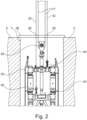
- FIG. 2 an upper end of a modified implement 20 is shown with a total of two measuring devices 40, with a milling frame 24 already being inserted into a floor 5 to form a hole 7 or slot.
- the two measuring devices 40 are attached to the milling frame 24 in a horizontally and vertically offset manner. From each measuring device 40, a measuring cable 32 extends upwards through a guide frame 36, which is placed on the surface of the ground above the hole 7. The measuring cables 32 are each guided through a predetermined fixed point 38 on the guide frame 36, which serve as a reference point for the position measurement and in particular the measurement of the verticality of the working device 20 in the ground 5.
- the measuring cables 32 extend exactly vertically to the vertical measuring axis through the respective fixed point 38. If a positional deviation occurs in the horizontal direction, this results in a deflection of at least one of the measuring cables 32 relative to the vertical measuring axis. This deviation or angulation can be determined by the measuring device 40, as follows with reference to the illustration Fig. 3 is explained in more detail. A vertical adjustment of the working device 20 takes place via the support cables 17, which are connected to the working device 20 via a suspension device 28.
- FIG. 3 A preferred embodiment of a measuring arrangement 30 according to the invention with a measuring device 40 is shown schematically in Fig. 3 shown.
- a measuring cable 32 is guided via a fastening sleeve 34 to an approximately spherical measuring device 40, which can determine a deviation and in particular an inclination of the measuring cable 32 relative to a vertical measuring axis with a high measuring accuracy.
- the Vertical measuring axis can result in particular from the direction of gravity.
- the measuring device 40 is connected to the working device 20 via a connecting device 50.
- the connecting device 50 has a connecting tube 52 extending in the vertical direction.
- the connecting pipe 52 includes a corrugated wall area and can be referred to as a corrugated pipe.
- a pull rope can extend within and along the connecting tube 52.
- the connecting tube 52 can preferably be filled with liquid.
- the connecting pipe 52 is firmly connected to the measuring device 40 via an upper fastening flange 55.
- the connecting tube 52 is attached to a pivot bearing 60 via a lower fastening flange 56, with which the connecting tube can be rotated about the vertical axis.
- a rotary drive 62 is provided below the pivot bearing 60, with which the connecting pipe 52 can be adjusted in defined positioning angles relative to the implement 20.
- the rotary drive 62 is connected to the implement 20 via a flange connection, the connection being provided either on the frame of the implement 20 or on the suspension device 28.
Landscapes
- Engineering & Computer Science (AREA)
- Mining & Mineral Resources (AREA)
- Civil Engineering (AREA)
- General Engineering & Computer Science (AREA)
- Structural Engineering (AREA)
- Life Sciences & Earth Sciences (AREA)
- General Life Sciences & Earth Sciences (AREA)
- Paleontology (AREA)
- Mechanical Engineering (AREA)
- A Measuring Device Byusing Mechanical Method (AREA)
- Earth Drilling (AREA)
- Investigation Of Foundation Soil And Reinforcement Of Foundation Soil By Compacting Or Drainage (AREA)
Claims (15)
- Ensemble de mesure pour la mesure d'une position, en particulier d'une verticalité, d'un appareil de travail (20) abaissable et réglable verticalement par rapport à un point fixe (38) supérieur, avec- au moins un câble de mesure (32) qui est relié d'une part à l'appareil de travail (20) réglable verticalement et s'étend d'autre part vers le point fixe (38),- au moins un dispositif de mesure (40) qui est relié au câble de mesure (32) afférent et est réalisé pour la mesure d'un angle d'inclinaison du câble de mesure (32) par rapport à un axe de mesure vertical et est agencé dans une zone de liaison entre le câble de mesure (32) et l'appareil de travail (20), et- au moins un dispositif de liaison (50) qui est agencé et réalisé entre le dispositif de mesure (40) et l'appareil de travail (20) afin de maintenir le dispositif de mesure (40) fixe en rotation autour de l'axe de mesure vertical et en même temps de manière inclinable par rapport à l'axe de mesure vertical au niveau de l'appareil de travail (20),
caractérisé en ce que- le dispositif de liaison (50) présente un tube de liaison (52) qui est agencé coaxialement à l'axe de mesure vertical et- le tube de liaison (52) est réalisé de manière rigide en torsion autour de l'axe de mesure vertical et de manière déviable par rapport à l'axe de mesure vertical. - Ensemble de mesure selon la revendication 1,
caractérisé en ce que
le tube de liaison (52) est formé comme un tuyau en un matériau flexible. - Ensemble de mesure selon la revendication 1 ou 2,
caractérisé en ce que
le tube de liaison (52) est réalisé au moins par sections comme un tube ondulé avec une zone de paroi (54) ondulée. - Ensemble de mesure selon la revendication 3,
caractérisé en ce que
le tube ondulé est fabriqué en métal, en particulier en acier. - Ensemble de mesure selon l'une quelconque des revendications 1 à 4,
caractérisé en ce que
le tube de liaison (52) est rempli d'un liquide incompressible. - Ensemble de mesure selon l'une quelconque des revendications 1 à 5,
caractérisé en ce que
un palier rotatif (60) est prévu au niveau de l'extrémité dirigée vers l'appareil de travail (20) du tube de liaison (52), avec lequel le tube de liaison (52) est rotatif autour de l'axe de mesure vertical, en particulier d'un angle de 180°. - Ensemble de mesure selon la revendication 6,
caractérisé en ce que
un entraînement rotatif (62) est agencé pour la rotation du tube de liaison (52) logé de manière rotative dans au moins une position de rotation différente et que le dispositif de mesure (40) est réalisé pour la mesure de l'angle d'inclinaison dans les différentes positions de rotation. - Ensemble de mesure selon l'une quelconque des revendications 1 à 7,
caractérisé en ce que
au moins deux câbles de mesure (32) sont prévus, lesquels sont montés à distance horizontale l'un de l'autre au niveau de l'appareil de travail (20). - Ensemble de mesure selon l'une quelconque des revendications 1 à 8,
caractérisé en ce que
un élément de traction, en particulier un câble de traction, est agencé à l'intérieur du tube de liaison (52). - Dispositif d'enlèvement pour la création d'un trou (7), en particulier d'une entaille, dans le sol (5), avec- un appareil de travail (20) qui présente au moins un outil d'enlèvement (26) pour l'enlèvement du sol (5),- un appareil de support (12), au niveau duquel l'appareil de travail (20) est logé de manière réglable verticalement pour l'introduction dans le sol (5), et- un ensemble de mesure (30) pour la mesure de la position, en particulier d'une verticalité, de l'appareil de travail (20) dans le sol (5),caractérisé en ce que
un ensemble de mesure (30) selon l'une quelconque des revendications 1 à 8 est agencé. - Dispositif d'enlèvement selon la revendication 10,
caractérisé en ce que
le câble de mesure (32) présente une densité qui est identique ou inférieure à la densité d'un liquide de support, avec lequel le trou (7) créé par l'appareil de travail (20) est rempli. - Dispositif d'enlèvement selon la revendication 10 ou 11,
caractérisé en ce quel'appareil de travail (20) est pourvu d'organes de réglage (25) commandables pour la modification de la position de l'appareil de travail (20) dans le trou (7) etune unité de commande et d'évaluation est prévue et réalisée au niveau de l'appareil de support (12) afin de contrôler en fonction des valeurs de mesure d'au moins un dispositif de mesure (40) une position de l'appareil de travail (20) et de la modifier par commande des organes de réglage (25). - Dispositif d'enlèvement selon l'une quelconque des revendications 10 à 12, caractérisé en ce que
un treuil (18) pour chaque câble de mesure (32) est prévu au niveau de l'appareil de support (12), par lequel le câble de mesure (32) peut être suivi par l'appareil de travail, sous une précontrainte prédéfinie. - Dispositif d'enlèvement selon l'une quelconque des revendications 10 à 13, caractérisé en ce que
l'au moins un point fixe (38) est réalisé et mesuré au niveau d'un cadre conducteur (36) qui est agencé à une extrémité supérieure du trou (7). - Dispositif d'enlèvement selon l'une quelconque des revendications 10 à 14, caractérisé en ce que
l'appareil de travail (20) est un excavateur de tranchées (22) avec au moins une roue de fraisage (27) entraînée qui est logée de manière rotative à une extrémité inférieure d'un cadre de fraisage (24) autour d'un axe de rotation horizontal.
Priority Applications (6)
| Application Number | Priority Date | Filing Date | Title |
|---|---|---|---|
| EP21164313.5A EP4063568B1 (fr) | 2021-03-23 | 2021-03-23 | Dispositif de mesure et dispositif d'enlèvement doté d'un dispositif de mesure |
| PCT/EP2022/056289 WO2022200074A1 (fr) | 2021-03-23 | 2022-03-11 | Ensemble de mesure et dispositif d'enlèvement comprenant un ensemble de mesure |
| JP2023558183A JP7547651B2 (ja) | 2021-03-23 | 2022-03-11 | 計測装置及び計測装置を有する除去装置 |
| KR1020237026033A KR20230125824A (ko) | 2021-03-23 | 2022-03-11 | 측정 장치 및 측정 장치를 가진 제거 장치 |
| CN202280015333.4A CN116888327A (zh) | 2021-03-23 | 2022-03-11 | 测量组件和带有测量组件的移除装置 |
| US18/546,391 US20240229404A9 (en) | 2021-03-23 | 2022-03-11 | Measuring arrangement and removal device with a measuring arrangement |
Applications Claiming Priority (1)
| Application Number | Priority Date | Filing Date | Title |
|---|---|---|---|
| EP21164313.5A EP4063568B1 (fr) | 2021-03-23 | 2021-03-23 | Dispositif de mesure et dispositif d'enlèvement doté d'un dispositif de mesure |
Publications (3)
| Publication Number | Publication Date |
|---|---|
| EP4063568A1 EP4063568A1 (fr) | 2022-09-28 |
| EP4063568C0 EP4063568C0 (fr) | 2023-10-04 |
| EP4063568B1 true EP4063568B1 (fr) | 2023-10-04 |
Family
ID=75203014
Family Applications (1)
| Application Number | Title | Priority Date | Filing Date |
|---|---|---|---|
| EP21164313.5A Active EP4063568B1 (fr) | 2021-03-23 | 2021-03-23 | Dispositif de mesure et dispositif d'enlèvement doté d'un dispositif de mesure |
Country Status (6)
| Country | Link |
|---|---|
| US (1) | US20240229404A9 (fr) |
| EP (1) | EP4063568B1 (fr) |
| JP (1) | JP7547651B2 (fr) |
| KR (1) | KR20230125824A (fr) |
| CN (1) | CN116888327A (fr) |
| WO (1) | WO2022200074A1 (fr) |
Family Cites Families (6)
| Publication number | Priority date | Publication date | Assignee | Title |
|---|---|---|---|---|
| DE4119212C2 (de) * | 1991-06-11 | 1996-06-27 | Bauer Spezialtiefbau | Verfahren zum Fräsen einer Schlitzwand |
| FR2755467B1 (fr) | 1996-11-06 | 1999-05-14 | Sol Comp Du | Dispositif de mesure de verticalite d'un engin de forage |
| ES2533573T3 (es) | 2012-01-31 | 2015-04-13 | Bauer Spezialtiefbau Gmbh | Procedimiento y disposición para la elaboración de un elemento de muro pantalla |
| ES2525921T3 (es) | 2012-08-13 | 2015-01-02 | Bauer Spezialtiefbau Gmbh | Procedimiento y dispositivo para producir y medir una perforación |
| FR3001251B1 (fr) | 2013-01-23 | 2017-05-26 | Soletanche Freyssinet | Procede de determination de la position d'un dispositif de coupe dans le sol a l'aide d'un chariot mobile |
| FR3078739B1 (fr) | 2018-03-09 | 2020-03-27 | Soletanche Freyssinet | Machine de forage comportant un dispositif de connexion pour un dispositif de mesure de verticalite |
-
2021
- 2021-03-23 EP EP21164313.5A patent/EP4063568B1/fr active Active
-
2022
- 2022-03-11 JP JP2023558183A patent/JP7547651B2/ja active Active
- 2022-03-11 CN CN202280015333.4A patent/CN116888327A/zh active Pending
- 2022-03-11 KR KR1020237026033A patent/KR20230125824A/ko unknown
- 2022-03-11 US US18/546,391 patent/US20240229404A9/en active Pending
- 2022-03-11 WO PCT/EP2022/056289 patent/WO2022200074A1/fr active Application Filing
Also Published As
| Publication number | Publication date |
|---|---|
| US20240229404A9 (en) | 2024-07-11 |
| KR20230125824A (ko) | 2023-08-29 |
| US20240133146A1 (en) | 2024-04-25 |
| JP7547651B2 (ja) | 2024-09-09 |
| JP2024511426A (ja) | 2024-03-13 |
| CN116888327A (zh) | 2023-10-13 |
| EP4063568A1 (fr) | 2022-09-28 |
| EP4063568C0 (fr) | 2023-10-04 |
| WO2022200074A1 (fr) | 2022-09-29 |
Similar Documents
| Publication | Publication Date | Title |
|---|---|---|
| DE102015105908B4 (de) | Bohrgerät zum Erstellen einer verrohrten Bohrung und Verfahren zum Betreiben eines Bohrgerätes | |
| EP2623677B1 (fr) | Procédé et agencement destinés à la fabrication d'un élément de paroi moulée | |
| EP0345650B1 (fr) | Appareil de forage d'ancrage | |
| EP0699888A2 (fr) | Détermination du diamètre ou de l'épaisseur d'éléments d'une paroi | |
| EP2410092B1 (fr) | Dispositif et procédé de fabrication de murs verticaux dans un sol de fondation | |
| EP3513039B1 (fr) | Procédé d'évaluation de signaux de mesure | |
| EP4063568B1 (fr) | Dispositif de mesure et dispositif d'enlèvement doté d'un dispositif de mesure | |
| EP2698499B1 (fr) | Procédé et dispositif de fabrication et de mesure d'un trou de forage | |
| DE102012112411B3 (de) | Pressbohrlenkvorrichtung | |
| DE4132314C1 (en) | Vehicle mounted piling drill with mast - on which travels carriage with rotary head and tool duct laterally offset w.r.t.carriage guideway | |
| EP0169393A1 (fr) | Dispositif pour la production de forages d'une section transversale inaccessible | |
| EP3907371B1 (fr) | Machine de travail et procédé de traitement d'un sol | |
| EP3819433B1 (fr) | Dispositif d'enlèvement de sol et procédé de production d'un trou dans le sol | |
| WO2022117777A1 (fr) | Dispositif de fonçage pour le fonçage d'un puits dans le sol, ayant un dispositif pour déterminer la position du dispositif de fonçage dans le sol | |
| EP3584370B1 (fr) | Engin de chantier et procédé de fonctionnement d'un engin de chantier | |
| DE3823784C2 (fr) | ||
| DE4211059C1 (fr) | ||
| DE19837546A1 (de) | Meßvorrichtung zum Bestimmen der Ausrichtung und des Verlaufs eines Bohrgestänges | |
| EP1790779A1 (fr) | Fraiseuse à rideau souterrainet procédé pour creuser des tranchées dans le sol | |
| EP3725955A1 (fr) | Benne à parois moulées et procédé de fabrication d'une mortaise dans le sol | |
| EP3879064B1 (fr) | Dispositif de traitement du sol et procédé de production d'un trou essentiellement vertical dans le sol | |
| EP4269699B1 (fr) | Engin de génie civil | |
| DE4420705A1 (de) | Verfahren und Vorrichtung zur kontinuierlichen automatischen Vermessung und Steuerung einer Vortriebsvorrichtung bei Tunnelbauten u. dgl. | |
| EP2245232B1 (fr) | Dispositif et procédé pour réaliser dans la terre des forages dont les coupes transversales se recoupent partiellement | |
| EP3272946B1 (fr) | Dispositif de guidage et procede de production d'une fente |
Legal Events
| Date | Code | Title | Description |
|---|---|---|---|
| PUAI | Public reference made under article 153(3) epc to a published international application that has entered the european phase |
Free format text: ORIGINAL CODE: 0009012 |
|
| STAA | Information on the status of an ep patent application or granted ep patent |
Free format text: STATUS: THE APPLICATION HAS BEEN PUBLISHED |
|
| AK | Designated contracting states |
Kind code of ref document: A1 Designated state(s): AL AT BE BG CH CY CZ DE DK EE ES FI FR GB GR HR HU IE IS IT LI LT LU LV MC MK MT NL NO PL PT RO RS SE SI SK SM TR |
|
| STAA | Information on the status of an ep patent application or granted ep patent |
Free format text: STATUS: REQUEST FOR EXAMINATION WAS MADE |
|
| 17P | Request for examination filed |
Effective date: 20230217 |
|
| RBV | Designated contracting states (corrected) |
Designated state(s): AL AT BE BG CH CY CZ DE DK EE ES FI FR GB GR HR HU IE IS IT LI LT LU LV MC MK MT NL NO PL PT RO RS SE SI SK SM TR |
|
| GRAP | Despatch of communication of intention to grant a patent |
Free format text: ORIGINAL CODE: EPIDOSNIGR1 |
|
| STAA | Information on the status of an ep patent application or granted ep patent |
Free format text: STATUS: GRANT OF PATENT IS INTENDED |
|
| GRAJ | Information related to disapproval of communication of intention to grant by the applicant or resumption of examination proceedings by the epo deleted |
Free format text: ORIGINAL CODE: EPIDOSDIGR1 |
|
| STAA | Information on the status of an ep patent application or granted ep patent |
Free format text: STATUS: REQUEST FOR EXAMINATION WAS MADE |
|
| GRAP | Despatch of communication of intention to grant a patent |
Free format text: ORIGINAL CODE: EPIDOSNIGR1 |
|
| INTG | Intention to grant announced |
Effective date: 20230509 |
|
| STAA | Information on the status of an ep patent application or granted ep patent |
Free format text: STATUS: GRANT OF PATENT IS INTENDED |
|
| INTC | Intention to grant announced (deleted) | ||
| INTG | Intention to grant announced |
Effective date: 20230601 |
|
| GRAS | Grant fee paid |
Free format text: ORIGINAL CODE: EPIDOSNIGR3 |
|
| GRAA | (expected) grant |
Free format text: ORIGINAL CODE: 0009210 |
|
| STAA | Information on the status of an ep patent application or granted ep patent |
Free format text: STATUS: THE PATENT HAS BEEN GRANTED |
|
| AK | Designated contracting states |
Kind code of ref document: B1 Designated state(s): AL AT BE BG CH CY CZ DE DK EE ES FI FR GB GR HR HU IE IS IT LI LT LU LV MC MK MT NL NO PL PT RO RS SE SI SK SM TR |
|
| REG | Reference to a national code |
Ref country code: GB Ref legal event code: FG4D Free format text: NOT ENGLISH |
|
| REG | Reference to a national code |
Ref country code: CH Ref legal event code: EP |
|
| REG | Reference to a national code |
Ref country code: IE Ref legal event code: FG4D Free format text: LANGUAGE OF EP DOCUMENT: GERMAN |
|
| REG | Reference to a national code |
Ref country code: DE Ref legal event code: R096 Ref document number: 502021001603 Country of ref document: DE |
|
| U01 | Request for unitary effect filed |
Effective date: 20231004 |
|
| U07 | Unitary effect registered |
Designated state(s): AT BE BG DE DK EE FI FR IT LT LU LV MT NL PT SE SI Effective date: 20231018 |
|
| PG25 | Lapsed in a contracting state [announced via postgrant information from national office to epo] |
Ref country code: GR Free format text: LAPSE BECAUSE OF FAILURE TO SUBMIT A TRANSLATION OF THE DESCRIPTION OR TO PAY THE FEE WITHIN THE PRESCRIBED TIME-LIMIT Effective date: 20240105 |
|
| PG25 | Lapsed in a contracting state [announced via postgrant information from national office to epo] |
Ref country code: IS Free format text: LAPSE BECAUSE OF FAILURE TO SUBMIT A TRANSLATION OF THE DESCRIPTION OR TO PAY THE FEE WITHIN THE PRESCRIBED TIME-LIMIT Effective date: 20240204 |
|
| U20 | Renewal fee paid [unitary effect] |
Year of fee payment: 4 Effective date: 20240312 |
|
| PG25 | Lapsed in a contracting state [announced via postgrant information from national office to epo] |
Ref country code: ES Free format text: LAPSE BECAUSE OF FAILURE TO SUBMIT A TRANSLATION OF THE DESCRIPTION OR TO PAY THE FEE WITHIN THE PRESCRIBED TIME-LIMIT Effective date: 20231004 |
|
| PG25 | Lapsed in a contracting state [announced via postgrant information from national office to epo] |
Ref country code: IS Free format text: LAPSE BECAUSE OF FAILURE TO SUBMIT A TRANSLATION OF THE DESCRIPTION OR TO PAY THE FEE WITHIN THE PRESCRIBED TIME-LIMIT Effective date: 20240204 Ref country code: GR Free format text: LAPSE BECAUSE OF FAILURE TO SUBMIT A TRANSLATION OF THE DESCRIPTION OR TO PAY THE FEE WITHIN THE PRESCRIBED TIME-LIMIT Effective date: 20240105 Ref country code: ES Free format text: LAPSE BECAUSE OF FAILURE TO SUBMIT A TRANSLATION OF THE DESCRIPTION OR TO PAY THE FEE WITHIN THE PRESCRIBED TIME-LIMIT Effective date: 20231004 |
|
| PG25 | Lapsed in a contracting state [announced via postgrant information from national office to epo] |
Ref country code: RS Free format text: LAPSE BECAUSE OF FAILURE TO SUBMIT A TRANSLATION OF THE DESCRIPTION OR TO PAY THE FEE WITHIN THE PRESCRIBED TIME-LIMIT Effective date: 20231004 Ref country code: PL Free format text: LAPSE BECAUSE OF FAILURE TO SUBMIT A TRANSLATION OF THE DESCRIPTION OR TO PAY THE FEE WITHIN THE PRESCRIBED TIME-LIMIT Effective date: 20231004 Ref country code: NO Free format text: LAPSE BECAUSE OF FAILURE TO SUBMIT A TRANSLATION OF THE DESCRIPTION OR TO PAY THE FEE WITHIN THE PRESCRIBED TIME-LIMIT Effective date: 20240104 Ref country code: HR Free format text: LAPSE BECAUSE OF FAILURE TO SUBMIT A TRANSLATION OF THE DESCRIPTION OR TO PAY THE FEE WITHIN THE PRESCRIBED TIME-LIMIT Effective date: 20231004 |
|
| REG | Reference to a national code |
Ref country code: DE Ref legal event code: R097 Ref document number: 502021001603 Country of ref document: DE |
|
| PG25 | Lapsed in a contracting state [announced via postgrant information from national office to epo] |
Ref country code: CZ Free format text: LAPSE BECAUSE OF FAILURE TO SUBMIT A TRANSLATION OF THE DESCRIPTION OR TO PAY THE FEE WITHIN THE PRESCRIBED TIME-LIMIT Effective date: 20231004 |
|
| PG25 | Lapsed in a contracting state [announced via postgrant information from national office to epo] |
Ref country code: SK Free format text: LAPSE BECAUSE OF FAILURE TO SUBMIT A TRANSLATION OF THE DESCRIPTION OR TO PAY THE FEE WITHIN THE PRESCRIBED TIME-LIMIT Effective date: 20231004 |
|
| PG25 | Lapsed in a contracting state [announced via postgrant information from national office to epo] |
Ref country code: SM Free format text: LAPSE BECAUSE OF FAILURE TO SUBMIT A TRANSLATION OF THE DESCRIPTION OR TO PAY THE FEE WITHIN THE PRESCRIBED TIME-LIMIT Effective date: 20231004 Ref country code: SK Free format text: LAPSE BECAUSE OF FAILURE TO SUBMIT A TRANSLATION OF THE DESCRIPTION OR TO PAY THE FEE WITHIN THE PRESCRIBED TIME-LIMIT Effective date: 20231004 Ref country code: RO Free format text: LAPSE BECAUSE OF FAILURE TO SUBMIT A TRANSLATION OF THE DESCRIPTION OR TO PAY THE FEE WITHIN THE PRESCRIBED TIME-LIMIT Effective date: 20231004 Ref country code: CZ Free format text: LAPSE BECAUSE OF FAILURE TO SUBMIT A TRANSLATION OF THE DESCRIPTION OR TO PAY THE FEE WITHIN THE PRESCRIBED TIME-LIMIT Effective date: 20231004 |
|
| PLBE | No opposition filed within time limit |
Free format text: ORIGINAL CODE: 0009261 |
|
| STAA | Information on the status of an ep patent application or granted ep patent |
Free format text: STATUS: NO OPPOSITION FILED WITHIN TIME LIMIT |
|
| 26N | No opposition filed |
Effective date: 20240705 |