EP4063333B1 - Herstellung einer metallform zur nachbildung eines bauteils mit vorbestimmter dreidimensionaler form - Google Patents
Herstellung einer metallform zur nachbildung eines bauteils mit vorbestimmter dreidimensionaler form Download PDFInfo
- Publication number
- EP4063333B1 EP4063333B1 EP21165146.8A EP21165146A EP4063333B1 EP 4063333 B1 EP4063333 B1 EP 4063333B1 EP 21165146 A EP21165146 A EP 21165146A EP 4063333 B1 EP4063333 B1 EP 4063333B1
- Authority
- EP
- European Patent Office
- Prior art keywords
- glass
- moldable
- nanocomposite
- manufacturing
- organic binder
- Prior art date
- Legal status (The legal status is an assumption and is not a legal conclusion. Google has not performed a legal analysis and makes no representation as to the accuracy of the status listed.)
- Active
Links
Images
Classifications
-
- B—PERFORMING OPERATIONS; TRANSPORTING
- B22—CASTING; POWDER METALLURGY
- B22C—FOUNDRY MOULDING
- B22C7/00—Patterns; Manufacture thereof so far as not provided for in other classes
-
- B—PERFORMING OPERATIONS; TRANSPORTING
- B29—WORKING OF PLASTICS; WORKING OF SUBSTANCES IN A PLASTIC STATE IN GENERAL
- B29C—SHAPING OR JOINING OF PLASTICS; SHAPING OF MATERIAL IN A PLASTIC STATE, NOT OTHERWISE PROVIDED FOR; AFTER-TREATMENT OF THE SHAPED PRODUCTS, e.g. REPAIRING
- B29C33/00—Moulds or cores; Details thereof or accessories therefor
- B29C33/38—Moulds or cores; Details thereof or accessories therefor characterised by the material or the manufacturing process
- B29C33/3842—Manufacturing moulds, e.g. shaping the mould surface by machining
- B29C33/3857—Manufacturing moulds, e.g. shaping the mould surface by machining by making impressions of one or more parts of models, e.g. shaped articles and including possible subsequent assembly of the parts
- B29C33/3892—Preparation of the model, e.g. by assembling parts
-
- B—PERFORMING OPERATIONS; TRANSPORTING
- B29—WORKING OF PLASTICS; WORKING OF SUBSTANCES IN A PLASTIC STATE IN GENERAL
- B29K—INDEXING SCHEME ASSOCIATED WITH SUBCLASSES B29B, B29C OR B29D, RELATING TO MOULDING MATERIALS OR TO MATERIALS FOR MOULDS, REINFORCEMENTS, FILLERS OR PREFORMED PARTS, e.g. INSERTS
- B29K2905/00—Use of metals, their alloys or their compounds, as mould material
-
- C—CHEMISTRY; METALLURGY
- C03—GLASS; MINERAL OR SLAG WOOL
- C03B—MANUFACTURE, SHAPING, OR SUPPLEMENTARY PROCESSES
- C03B19/00—Other methods of shaping glass
- C03B19/06—Other methods of shaping glass by sintering, e.g. by cold isostatic pressing of powders and subsequent sintering, by hot pressing of powders, by sintering slurries or dispersions not undergoing a liquid phase reaction
- C03B19/066—Other methods of shaping glass by sintering, e.g. by cold isostatic pressing of powders and subsequent sintering, by hot pressing of powders, by sintering slurries or dispersions not undergoing a liquid phase reaction for the production of quartz or fused silica articles
Definitions
- the present invention relates to a method of manufacturing a metal mold for replicating a component having a predetermined three-dimensional shape. Further, the present invention relates to a method of replicating a component having a predetermined three-dimensional shape.
- Polymeric components i.e. components made of a polymeric material
- replication processes such as injection molding, for instance, allow the fast and scalable manufacturing of polymeric components as they do not require any shape-defining step during the manufacturing. That is, in these replication processes, a thermoplastic or a resin is injected into a molding tool and then hardened, with the molding tool already defining the final three-dimensional shape of the polymeric component.
- resins can result in a crosslinked structure when hardened.
- the thermoplastic or the resin which is in a moldable state when injected into the molding tool needs to be hardened.
- hardening is achieved upon cooling, which turns the softened thermoplastic into the polymeric component having the final three-dimensional shape.
- hardening is achieved upon curing or polymerizing initiated by an external stimulus such as heat or irradiation, which turns the liquid constituent(s) of the resin into the polymeric component having the final three-dimensional shape.
- predetermined three-dimensional shape Since the final three-dimensional shape of the polymeric component is determined in advance by the shape of the molding tool, it is commonly referred to as predetermined three-dimensional shape.
- the shape of the molding tool is the inverse of the final three-dimensional shape of the polymeric component. In other words, the molding tool has the predetermined three-dimensional shape inverted.
- Replication processes like injection molding allow the shaping of very intricate structures which are only limited by the surface properties of the molding tool.
- metal molds have been proven to be particularly suitable as molding tools, since they have sufficient durability so that they can be used over a long period of time for manufacturing thousands of polymeric components using the same molding tool.
- C. Richter et al. Progress in Biomedical Optics and Imaging, 2017, vol. 10061 , describes a fabrication process of molding tools for polymer replication, the process comprising: generating a microstructure in a photoresist via lithography; casting the microstructure into a high-temperature silicone which serves as an original mold for creation of a metal molding tool; and melting an eutectic alloy of Sn, Ag and Cu under light pressure directly inside of the silicone within an oven to obtain the metal molding tool after cooling to room temperature.
- the secondary structure may be first immersed in a solution containing one of the glass-forming precursors, and may then be exposed to physical or chemical vapor deposition containing or generating another one of the glass-forming precursors.
- the cavities of the secondary structure may be filled with the at least one glass-forming precursor even before debinding of the primary structure is completed. In this case, it is the partially debound primary structure which is filled with the at least one glass-forming precursor.
- step (iv) the secondary structure obtained in step (ii) optionally filled with at least one glass-forming precursor in step (iii) is sintered. Thereby, the glass-based mold is obtained.
- Suitable sintering conditions are known to the skilled person and are routinely selected as appropriate.
- the temperature applied during sintering is typically in the range from 700 °C to 1600 °C
- the heating rate is typically in the range from 1 °C/min to 10 °C/min, e.g. 5 °C/min
- the holding time is typically in the range from 0.5 hours to 8 hours, e.g. 4 hours, depending on the size of the glass-based mold to be obtained.
- the secondary structure may be pre-sintered at an intermediate temperature in order to convert the precursor of the ceramic material into the ceramic material, and/or in order to convert the glass-forming precursor into glass.
- pre-sintering may be carried out at a temperature in the range from 400 °C to 700 °C.
- the glass particles dispersed in the moldable nanocomposite are fused silica glass particles, it is possible to select both a comparatively high heating rate as well as a comparatively high cooling rate, taking account of the low coefficient of thermal expansion and taking account of the high thermal shock resistance of fused silica glass.
- sintering does not require the application of pressure.
- sintering in step (iv) can be suitably carried out at a pressure below atmospheric pressure, e.g. at a pressure of at most 0.1 mbar, preferably at most 0.01 mbar, and particularly preferably at most 0.001 mbar. Since sintering can be carried out at atmospheric pressure or even below, there are no particular requirements to be complied with in the present invention regarding the sintering furnace.
- the metal may be molten inside the glass-based mold or may be molten outside the glass-based mold and poured onto or into the glass-based mold. After completion thereof, the metal is solidified by cooling.
- the glass-based mold may be pressed into a metal substrate. In order to do so, the metal substrate needs to be malleable, either at room temperature or at elevated temperature. Metals which can be suitably pressed include but are not limited to aluminum and copper.
- the metal mold can be used as obtained and does not require any post-processing. However, the metal mold may be subjected to post-processing, e.g. by means of subtractive or additive manufacturing processes, in order to remove features present in the template or in order to add features not present in the template used for fabricating the glass-based mold, for instance.
- the component may be replicated by any replication process known in the art using the metal mold obtained in accordance with the present invention.
- the component may be replicated by means of injection molding, blow molding, hot embossing, thermoforming, or injection compression molding, without, however, being limited thereto.
- the present invention is not further limited, either.
- the replicated component is made of a polymeric material.
- the polymeric material may be derived from a thermoplastic or may be derived from a resin in the same manner as outlined above for the template.
- the present invention with the above-described manufacturing method allows the provision of a metal mold in a cost-efficient manner so as to be extendible to an industrial scale, and at the same time, allows the provision of a metal mold having adequate surface properties, e.g. low roughness and absence of defects.
- the predetermined three-dimensional shape of the component to be replicated is transferred into the metal mold without the need of any shape-defining step as it is required in subtractive or additive manufacturing.
- the transfer of the predetermined three-dimensional shape can be accomplished on the basis of a glass-based mold having the predetermined three-dimensional shape, which is obtained during the manufacturing. Once the glass-based mold has been obtained, the step of replicating the glass-based mold into the metal mold may be repeated several times, as required, using the same or a different glass-based mold.
- the present invention with the above-described replication method allows the provision of a replicated component which can be suitably used in various technical fields.
- the latter is particularly suited in the field of optics, e.g. as a lens, where high precision is essential.
- the present invention is further illustrated by the following Working Example without, however, being limited thereto.
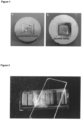
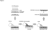
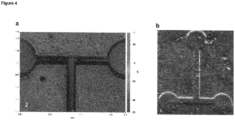
- a microfluidic channel as the component to be replicated was obtained by means of microlithography.
- a two-part resin based on polydimethylsiloxane was cast against the microfluidic channel, followed by hardening, i.e. curing which was initiated by mixing as the external stimulus, leading to a crosslinked structure.
- the template was replicated using a moldable nanocomposite comprising an organic binder and glass particles dispersed therein.
- a moldable nanocomposite a commercially available product was used ("Glassomer L50", a room-temperature liquid fused silica nanocomposite which can be hardened upon curing with UV irradiation).
- Glassomer L50 a room-temperature liquid fused silica nanocomposite which can be hardened upon curing with UV irradiation.
- the moldable nanocomposite was cast against the template, followed by hardening, i.e. curing with UV irradiation. After debinding by means of thermal treatment and after sintering, a glass-based mold made of highly pure fused silica glass was obtained.
- the moldable nanocomposite used herein allowed the facile replication of the template into a temperaturestable glass-based mold.
- nickel was molten at a temperature of 920 °C and poured onto the glass-based mold for replicating the glass-based mold into a metal mold. After cooling to room temperature, a high-quality metal mold was obtained which could be used as obtained for replicating the microfluidic channel as the component to be replicated.
Landscapes
- Engineering & Computer Science (AREA)
- Manufacturing & Machinery (AREA)
- Mechanical Engineering (AREA)
- Chemical & Material Sciences (AREA)
- Dispersion Chemistry (AREA)
- Materials Engineering (AREA)
- Organic Chemistry (AREA)
- Moulds For Moulding Plastics Or The Like (AREA)
- Moulds, Cores, Or Mandrels (AREA)
Claims (15)
- Verfahren zur Herstellung einer Metallform zum Replizieren eines Bauteils mit einer vorbestimmten dreidimensionalen Gestalt, wobei das Herstellungsverfahren umfasst:(a) Erzeugen einer Form auf Glasbasis unter Verwendung eines formbaren Nanokomposits, umfassend ein organisches Bindemittel und darin dispergierte Glasteilchen, wobei die Form auf Glasbasis die vorbestimmte dreidimensionale Gestalt aufweist und wie folgt erhalten wird:(i) Formen des formbaren Nanokomposits in die vorbestimmte dreidimensionale Gestalt vor, während und/oder nach Härten des organischen Bindemittels, wodurch eine Primärstruktur erhalten wird;(ii) Entbindern der Primärstruktur, erhalten in Schritt (i), durch Entfernen des organischen Bindemittels, wodurch eine Sekundärstruktur erhalten wird, wobei die Sekundärstruktur darin gebildete Hohlräume aufweist;(iii) gegebenenfalls Füllen der Hohlräume der Sekundärstruktur, erhalten in Schritt (ii), mit mindestens einem Präkursor zur Glasbildung; und(iv) Sintern der Sekundärstruktur, erhalten in Schritt (ii), gegebenenfalls mit mindestens einem Präkursor zur Glasbildung in Schritt (iii) gefüllt, wodurch die Form auf Glasbasis erhalten wird; und(b) Replizieren der Form auf Glasbasis, erhalten in Schritt (a), durch Schmelzen eines Metalls innerhalb der Form auf Glasbasis oder durch Schmelzen eines Metalls außerhalb der Form auf Glasbasis und Gießen desselben auf oder in die Form auf Glasbasis, gefolgt von Abkühlen, oder durch Drücken der Form auf Glasbasis in ein verformbares Metallsubstrat, wodurch die Metallform zum Replizieren des Bauteils erhalten wird, wobei die Metallform die vorbestimmte dreidimensionale Gestalt invertiert aufweist,wobei die Glasteilchen des formbaren Nanokomposits eine erste Sorte von Glasteilchen mit einem Durchmesser im Bereich von 5 nm bis 500 nm aufweisen.
- Herstellungsverfahren nach Anspruch 1, wobei das organische Bindemittel des formbaren Nanokomposits ein Thermoplast ist, welcher durch Abkühlen gehärtet werden kann.
- Herstellungsverfahren nach Anspruch 1, wobei das organische Bindemittel des formbaren Nanokomposits ein Harz ist, welches durch Aushärten oder Polymerisieren, initiiert durch einen externen Stimulus, gehärtet werden kann.
- Herstellungsverfahren nach einem der Ansprüche 1 bis 3, wobei die Glasteilchen des formbaren Nanokomposits Quarzglasteilchen sind.
- Herstellungsverfahren nach einem der Ansprüche 1 bis 4, wobei der Durchmesser der ersten Sorte von Glasteilchen im Bereich von 7 nm bis 400 nm liegt.
- Herstellungsverfahren nach einem der Ansprüche 1 bis 5, wobei die Glasteilchen des formbaren Nanokomposits eine zweite Sorte von Glasteilchen mit einem Durchmesser im Bereich von 2 µm bis 50 µm zusätzlich zur ersten Sorte von Glasteilchen umfassen.
- Herstellungsverfahren nach einem der Ansprüche 1 bis 6, wobei das formbare Nanokomposit weiter ein Phasenbildungsmittel, dispergiert in dem organischen Bindemittel, umfasst, wobei das Phasenbildungsmittel bei Raumtemperatur fest oder viskos ist und eine innere Phase in dem organischen Bindemittel bildet.
- Verfahren nach einem der Ansprüche 1 bis 7, wobei das formbare Nanokomposit mittels eines subtraktiven Herstellungsprozesses, eines additiven Herstellungsprozesses, eines Replizierungsprozesses oder einer Kombination hiervon in Schritt (i) geformt wird.
- Verfahren nach einem der Ansprüche 1 bis 8, wobei das formbare Nanokomposit durch Vergießen des formbaren Nanokomposits gegen eine Matrize, gefolgt von Härten, in Schritt (i) geformt wird, wobei die Matrize die vorbestimmte dreidimensionale Gestalt invertiert aufweist.
- Herstellungsverfahren nach Anspruch 9, wobei die Matrize aus einem polymeren Material ist.
- Herstellungsverfahren nach Anspruch 9 oder 10, wobei die Matrize vorab mittels eines subtraktiven Herstellungsprozesses, eines additiven Herstellungsprozesses, eines Replizierungsprozesses oder einer Kombination hiervon erhalten wird.
- Herstellungsverfahren nach einem der Ansprüche 1 bis 11, wobei die Primärstruktur, erhalten in Schritt (i), mittels thermischer Behandlung, chemischer Reaktion, reduziertem Druck, Lösungsmittel- oder Gasphasenextraktion oder einer Kombination hiervon in Schritt (ii) entbindert wird.
- Verfahren zum Replizieren eines Bauteils mit einer vorbestimmten dreidimensionalen Gestalt, wobei das Replizierungsverfahren umfasst:Erhalten einer Metallform durch das Herstellungsverfahren nach einem der Ansprüche 1 bis 12; undVerwenden der Metallform zum Replizieren des Bauteils.
- Replizierungsverfahren nach Anspruch 13, wobei das Bauteil mittels Spritzgie-ßen, Blasformen, Heißprägen, Thermoformen oder Spritzprägen repliziert wird.
- Replizierungsverfahren nach Anspruch 13 oder 14, wobei das replizierte Bauteil aus einem polymeren Material ist.
Priority Applications (8)
| Application Number | Priority Date | Filing Date | Title |
|---|---|---|---|
| EP21165146.8A EP4063333B1 (de) | 2021-03-26 | 2021-03-26 | Herstellung einer metallform zur nachbildung eines bauteils mit vorbestimmter dreidimensionaler form |
| US18/549,117 US12285886B2 (en) | 2021-03-26 | 2022-03-28 | Manufacturing of a metal mold for replicating a component having a predetermined three-dimensional shape |
| JP2023558433A JP7723439B2 (ja) | 2021-03-26 | 2022-03-28 | 予め決められた三次元形状を有する構成要素を複製するための金型の製造 |
| PCT/EP2022/058114 WO2022200628A1 (en) | 2021-03-26 | 2022-03-28 | Manufacturing of a metal mold for replicating a component having a predetermined three-dimensional shape |
| CA3212590A CA3212590A1 (en) | 2021-03-26 | 2022-03-28 | Manufacturing of a metal mold for replicating a component having a predetermined three-dimensional shape |
| AU2022242780A AU2022242780A1 (en) | 2021-03-26 | 2022-03-28 | Manufacturing of a metal mold for replicating a component having a predetermined three-dimensional shape |
| KR1020237036156A KR20230162648A (ko) | 2021-03-26 | 2022-03-28 | 미리 결정된 3차원 형상을 갖는 부품을 복제하기 위한 금속 금형의 제조 |
| CN202280024830.0A CN117098736B (zh) | 2021-03-26 | 2022-03-28 | 用于复制具有预定的三维形状的组件的金属模具的制造 |
Applications Claiming Priority (1)
| Application Number | Priority Date | Filing Date | Title |
|---|---|---|---|
| EP21165146.8A EP4063333B1 (de) | 2021-03-26 | 2021-03-26 | Herstellung einer metallform zur nachbildung eines bauteils mit vorbestimmter dreidimensionaler form |
Publications (3)
| Publication Number | Publication Date |
|---|---|
| EP4063333A1 EP4063333A1 (de) | 2022-09-28 |
| EP4063333C0 EP4063333C0 (de) | 2025-01-01 |
| EP4063333B1 true EP4063333B1 (de) | 2025-01-01 |
Family
ID=75377633
Family Applications (1)
| Application Number | Title | Priority Date | Filing Date |
|---|---|---|---|
| EP21165146.8A Active EP4063333B1 (de) | 2021-03-26 | 2021-03-26 | Herstellung einer metallform zur nachbildung eines bauteils mit vorbestimmter dreidimensionaler form |
Country Status (8)
| Country | Link |
|---|---|
| US (1) | US12285886B2 (de) |
| EP (1) | EP4063333B1 (de) |
| JP (1) | JP7723439B2 (de) |
| KR (1) | KR20230162648A (de) |
| CN (1) | CN117098736B (de) |
| AU (1) | AU2022242780A1 (de) |
| CA (1) | CA3212590A1 (de) |
| WO (1) | WO2022200628A1 (de) |
Families Citing this family (1)
| Publication number | Priority date | Publication date | Assignee | Title |
|---|---|---|---|---|
| EP3967666A1 (de) | 2020-09-14 | 2022-03-16 | Glassomer GmbH | Herstellung und thermische formgebung von transparentem glas |
Family Cites Families (30)
| Publication number | Priority date | Publication date | Assignee | Title |
|---|---|---|---|---|
| GB1356919A (en) * | 1970-04-17 | 1974-06-19 | Ici Ltd | Glass reinforced polymer composites |
| US5085938A (en) * | 1989-11-29 | 1992-02-04 | Ppg Industries, Inc. | Chemically treated fibers and method of preparing and method of using to reinforce polymers |
| JP4198149B2 (ja) * | 1997-05-28 | 2008-12-17 | 三菱エンジニアリングプラスチックス株式会社 | 熱可塑性樹脂成形用の金型組立体及び成形品の製造方法 |
| WO2000048775A2 (en) | 1999-02-18 | 2000-08-24 | Corning Incorporated | Titanium-containing silica glass honeycomb structure from silica soot extrusion |
| JP4671500B2 (ja) * | 2000-12-26 | 2011-04-20 | 京セラ株式会社 | 配線基板の製造方法 |
| JP2005097103A (ja) * | 2003-09-22 | 2005-04-14 | Heraeus Quarzglas Gmbh & Co Kg | 複合材料からキャスティングを製造する方法とセラミックもしくはガラス質の複合材料のキャスティング |
| US7051783B1 (en) * | 2005-01-31 | 2006-05-30 | Ndm Tooling Associates Inc. | Precision molding method |
| US20070154666A1 (en) * | 2005-12-31 | 2007-07-05 | Coonan Everett W | Powder injection molding of glass and glass-ceramics |
| JP5326121B2 (ja) * | 2010-12-27 | 2013-10-30 | トーカロ株式会社 | 溶融ガラス塊成形用金型およびその製造方法 |
| CN102397986A (zh) * | 2011-11-01 | 2012-04-04 | 昆明理工大学 | 一种利用陶瓷模型制备金属磨球模具的方法 |
| DE102012020509A1 (de) * | 2012-10-19 | 2014-06-12 | Ask Chemicals Gmbh | Formstoffmischungen auf der Basis anorganischer Bindemittel und Verfahren zur Herstellung von Formen und Kerne für den Metallguss |
| DE102012113073A1 (de) * | 2012-12-22 | 2014-07-10 | Ask Chemicals Gmbh | Formstoffmischungen enthaltend Aluminiumoxide und/oder Aluminium/Silizium-Mischoxide in partikulärer Form |
| JP6587136B2 (ja) | 2015-11-09 | 2019-10-09 | 国立研究開発法人産業技術総合研究所 | 成形型及び成形体の製造方法 |
| KR101746128B1 (ko) * | 2015-11-18 | 2017-06-13 | 경일대학교산학협력단 | MgAl2O4 Spinel 성형체의 제조방법 |
| US12351718B2 (en) * | 2016-06-06 | 2025-07-08 | Lawrence Livermore National Security, Llc | Engineered feedstocks for additive manufacture of glass |
| DE102016012003A1 (de) * | 2016-10-06 | 2018-04-12 | Karlsruher Institut für Technologie | Zusammensetzung und Verfahren zur Herstellung eines Formkörpers aus hochreinem, transparentem Quarzglas mittels additiver Fertigung |
| US11735413B2 (en) * | 2016-11-01 | 2023-08-22 | Versum Materials Us, Llc | Precursors and flowable CVD methods for making low-k films to fill surface features |
| DE102018200607A1 (de) * | 2018-01-15 | 2019-07-18 | Reinsicht Gmbh | Verfahren zur Erzeugung von für die Herstellung von Faserverbundkörpern oder Gussteilen aus Metall oder Kunststoff geeigneten Formen und Kernen, bei dem Verfahren einsetzbare Formgrundstoffe und Binder sowie gemäß dem Verfahren hergestellte Formen und Kerne |
| CN108516818B (zh) * | 2018-05-25 | 2021-03-26 | 江苏师范大学 | 一种基于改进的Isobam凝胶体系制备YAG透明陶瓷的方法 |
| WO2020120458A1 (de) * | 2018-12-14 | 2020-06-18 | Fraunhofer-Gesellschaft zur Förderung der angewandten Forschung e.V. | Verfahren zur herstellung von dünnen transparenten keramischen teilen und dünne transparente keramische teile |
| CN109650853B (zh) * | 2019-02-27 | 2021-08-17 | 湖南英捷高科技有限责任公司 | 一种透明陶瓷自锁托槽的制备方法 |
| WO2020200424A1 (en) * | 2019-04-02 | 2020-10-08 | Emery Oleochemicals Gmbh | Sinterable feedstock for use in 3d printing devices |
| JP7210370B2 (ja) * | 2019-04-26 | 2023-01-23 | 日本山村硝子株式会社 | 硝子成形用型の製造方法 |
| US10940639B1 (en) * | 2020-01-29 | 2021-03-09 | The Florida International University Board Of Trustees | Glass scintillators and methods of manufacturing the same |
| CN111499371A (zh) * | 2020-04-08 | 2020-08-07 | 哈尔滨工业大学 | 一种镁铝尖晶石透明陶瓷的制备方法 |
| CN111454067B (zh) * | 2020-05-30 | 2022-07-01 | 浙江昶研新材料有限公司 | 一种透明陶瓷正畸托槽及其制备方法 |
| EP3967666A1 (de) * | 2020-09-14 | 2022-03-16 | Glassomer GmbH | Herstellung und thermische formgebung von transparentem glas |
| CN112299828A (zh) * | 2020-11-09 | 2021-02-02 | 新沂市锡沂高新材料产业技术研究院有限公司 | 一种应用于5g太阳能手机的透明陶瓷背板的制备方法 |
| EP4063118A1 (de) * | 2021-03-26 | 2022-09-28 | Glassomer GmbH | Material und verfahren zur herstellung und formgebung von transparentem mehrkomponentenquarzglas |
| EP4063337A1 (de) * | 2021-03-26 | 2022-09-28 | Glassomer GmbH | Material und verfahren zur herstellung und formgebung von transparenten keramiken |
-
2021
- 2021-03-26 EP EP21165146.8A patent/EP4063333B1/de active Active
-
2022
- 2022-03-28 KR KR1020237036156A patent/KR20230162648A/ko active Pending
- 2022-03-28 AU AU2022242780A patent/AU2022242780A1/en active Pending
- 2022-03-28 JP JP2023558433A patent/JP7723439B2/ja active Active
- 2022-03-28 WO PCT/EP2022/058114 patent/WO2022200628A1/en not_active Ceased
- 2022-03-28 CN CN202280024830.0A patent/CN117098736B/zh active Active
- 2022-03-28 US US18/549,117 patent/US12285886B2/en active Active
- 2022-03-28 CA CA3212590A patent/CA3212590A1/en active Pending
Also Published As
| Publication number | Publication date |
|---|---|
| WO2022200628A1 (en) | 2022-09-29 |
| CN117098736A (zh) | 2023-11-21 |
| AU2022242780A1 (en) | 2023-08-31 |
| CN117098736B (zh) | 2026-03-24 |
| CA3212590A1 (en) | 2022-09-29 |
| JP7723439B2 (ja) | 2025-08-14 |
| US20240157608A1 (en) | 2024-05-16 |
| EP4063333C0 (de) | 2025-01-01 |
| KR20230162648A (ko) | 2023-11-28 |
| EP4063333A1 (de) | 2022-09-28 |
| JP2024511435A (ja) | 2024-03-13 |
| US12285886B2 (en) | 2025-04-29 |
Similar Documents
| Publication | Publication Date | Title |
|---|---|---|
| EP4063118A1 (de) | Material und verfahren zur herstellung und formgebung von transparentem mehrkomponentenquarzglas | |
| EP4063337A1 (de) | Material und verfahren zur herstellung und formgebung von transparenten keramiken | |
| JP7765101B2 (ja) | 透明ガラスの製造及び熱成形 | |
| US12285886B2 (en) | Manufacturing of a metal mold for replicating a component having a predetermined three-dimensional shape | |
| JP6862241B2 (ja) | 焼結シリカ部品の製造方法 | |
| CN111825333B (zh) | 一种玻璃浆料及其制备方法和3d打印玻璃器件的方法 | |
| Zhang et al. | Characterization of near-zero pressure powder injection moulding with sacrificial mould by using fingerprint geometries | |
| US20220193765A1 (en) | Stereolithography process for manufacturing a copper part having a low resistivity | |
| TW202449060A (zh) | 具有鈍化奈米顆粒與材料之壓印組成物及其製造製程 | |
| KR20040051879A (ko) | 유리 성형용 초경합금제 마이크로 몰드인서트 및 그 제조방법 |
Legal Events
| Date | Code | Title | Description |
|---|---|---|---|
| PUAI | Public reference made under article 153(3) epc to a published international application that has entered the european phase |
Free format text: ORIGINAL CODE: 0009012 |
|
| STAA | Information on the status of an ep patent application or granted ep patent |
Free format text: STATUS: THE APPLICATION HAS BEEN PUBLISHED |
|
| AK | Designated contracting states |
Kind code of ref document: A1 Designated state(s): AL AT BE BG CH CY CZ DE DK EE ES FI FR GB GR HR HU IE IS IT LI LT LU LV MC MK MT NL NO PL PT RO RS SE SI SK SM TR |
|
| STAA | Information on the status of an ep patent application or granted ep patent |
Free format text: STATUS: REQUEST FOR EXAMINATION WAS MADE |
|
| 17P | Request for examination filed |
Effective date: 20221027 |
|
| RBV | Designated contracting states (corrected) |
Designated state(s): AL AT BE BG CH CY CZ DE DK EE ES FI FR GB GR HR HU IE IS IT LI LT LU LV MC MK MT NL NO PL PT RO RS SE SI SK SM TR |
|
| RIC1 | Information provided on ipc code assigned before grant |
Ipc: B29C 33/38 20060101ALI20240613BHEP Ipc: B22C 7/00 20060101ALI20240613BHEP Ipc: C03B 19/06 20060101AFI20240613BHEP |
|
| GRAP | Despatch of communication of intention to grant a patent |
Free format text: ORIGINAL CODE: EPIDOSNIGR1 |
|
| STAA | Information on the status of an ep patent application or granted ep patent |
Free format text: STATUS: GRANT OF PATENT IS INTENDED |
|
| INTG | Intention to grant announced |
Effective date: 20240723 |
|
| GRAS | Grant fee paid |
Free format text: ORIGINAL CODE: EPIDOSNIGR3 |
|
| GRAA | (expected) grant |
Free format text: ORIGINAL CODE: 0009210 |
|
| STAA | Information on the status of an ep patent application or granted ep patent |
Free format text: STATUS: THE PATENT HAS BEEN GRANTED |
|
| AK | Designated contracting states |
Kind code of ref document: B1 Designated state(s): AL AT BE BG CH CY CZ DE DK EE ES FI FR GB GR HR HU IE IS IT LI LT LU LV MC MK MT NL NO PL PT RO RS SE SI SK SM TR |
|
| REG | Reference to a national code |
Ref country code: GB Ref legal event code: FG4D |
|
| REG | Reference to a national code |
Ref country code: CH Ref legal event code: EP |
|
| REG | Reference to a national code |
Ref country code: DE Ref legal event code: R096 Ref document number: 602021024093 Country of ref document: DE |
|
| REG | Reference to a national code |
Ref country code: IE Ref legal event code: FG4D |
|
| U01 | Request for unitary effect filed |
Effective date: 20250129 |
|
| U07 | Unitary effect registered |
Designated state(s): AT BE BG DE DK EE FI FR IT LT LU LV MT NL PT RO SE SI Effective date: 20250204 |
|
| RAP4 | Party data changed (patent owner data changed or rights of a patent transferred) |
Owner name: ALBERT-LUDWIGS-UNIVERSITAET FREIBURG Owner name: GLASSOMER GMBH |
|
| U1H | Name or address of the proprietor changed after the registration of the unitary effect |
Owner name: ALBERT-LUDWIGS-UNIVERSITAET FREIBURG; DE Owner name: GLASSOMER GMBH; DE |
|
| U20 | Renewal fee for the european patent with unitary effect paid |
Year of fee payment: 5 Effective date: 20250326 |
|
| PG25 | Lapsed in a contracting state [announced via postgrant information from national office to epo] |
Ref country code: PL Free format text: LAPSE BECAUSE OF FAILURE TO SUBMIT A TRANSLATION OF THE DESCRIPTION OR TO PAY THE FEE WITHIN THE PRESCRIBED TIME-LIMIT Effective date: 20250101 |
|
| PG25 | Lapsed in a contracting state [announced via postgrant information from national office to epo] |
Ref country code: ES Free format text: LAPSE BECAUSE OF FAILURE TO SUBMIT A TRANSLATION OF THE DESCRIPTION OR TO PAY THE FEE WITHIN THE PRESCRIBED TIME-LIMIT Effective date: 20250101 |
|
| PG25 | Lapsed in a contracting state [announced via postgrant information from national office to epo] |
Ref country code: NO Free format text: LAPSE BECAUSE OF FAILURE TO SUBMIT A TRANSLATION OF THE DESCRIPTION OR TO PAY THE FEE WITHIN THE PRESCRIBED TIME-LIMIT Effective date: 20250401 Ref country code: IS Free format text: LAPSE BECAUSE OF FAILURE TO SUBMIT A TRANSLATION OF THE DESCRIPTION OR TO PAY THE FEE WITHIN THE PRESCRIBED TIME-LIMIT Effective date: 20250501 |
|
| PG25 | Lapsed in a contracting state [announced via postgrant information from national office to epo] |
Ref country code: HR Free format text: LAPSE BECAUSE OF FAILURE TO SUBMIT A TRANSLATION OF THE DESCRIPTION OR TO PAY THE FEE WITHIN THE PRESCRIBED TIME-LIMIT Effective date: 20250101 |
|
| PG25 | Lapsed in a contracting state [announced via postgrant information from national office to epo] |
Ref country code: GR Free format text: LAPSE BECAUSE OF FAILURE TO SUBMIT A TRANSLATION OF THE DESCRIPTION OR TO PAY THE FEE WITHIN THE PRESCRIBED TIME-LIMIT Effective date: 20250402 |
|
| PGFP | Annual fee paid to national office [announced via postgrant information from national office to epo] |
Ref country code: CH Payment date: 20250401 Year of fee payment: 5 |
|
| PG25 | Lapsed in a contracting state [announced via postgrant information from national office to epo] |
Ref country code: CZ Free format text: LAPSE BECAUSE OF FAILURE TO SUBMIT A TRANSLATION OF THE DESCRIPTION OR TO PAY THE FEE WITHIN THE PRESCRIBED TIME-LIMIT Effective date: 20250101 |
|
| PG25 | Lapsed in a contracting state [announced via postgrant information from national office to epo] |
Ref country code: SM Free format text: LAPSE BECAUSE OF FAILURE TO SUBMIT A TRANSLATION OF THE DESCRIPTION OR TO PAY THE FEE WITHIN THE PRESCRIBED TIME-LIMIT Effective date: 20250101 |
|
| PG25 | Lapsed in a contracting state [announced via postgrant information from national office to epo] |
Ref country code: MC Free format text: LAPSE BECAUSE OF FAILURE TO SUBMIT A TRANSLATION OF THE DESCRIPTION OR TO PAY THE FEE WITHIN THE PRESCRIBED TIME-LIMIT Effective date: 20250101 |
|
| PG25 | Lapsed in a contracting state [announced via postgrant information from national office to epo] |
Ref country code: SK Free format text: LAPSE BECAUSE OF FAILURE TO SUBMIT A TRANSLATION OF THE DESCRIPTION OR TO PAY THE FEE WITHIN THE PRESCRIBED TIME-LIMIT Effective date: 20250101 |
|
| PLBE | No opposition filed within time limit |
Free format text: ORIGINAL CODE: 0009261 |
|
| STAA | Information on the status of an ep patent application or granted ep patent |
Free format text: STATUS: NO OPPOSITION FILED WITHIN TIME LIMIT |
|
| REG | Reference to a national code |
Ref country code: CH Ref legal event code: L10 Free format text: ST27 STATUS EVENT CODE: U-0-0-L10-L00 (AS PROVIDED BY THE NATIONAL OFFICE) Effective date: 20251112 |
|
| 26N | No opposition filed |
Effective date: 20251002 |
|
| PG25 | Lapsed in a contracting state [announced via postgrant information from national office to epo] |
Ref country code: IE Free format text: LAPSE BECAUSE OF NON-PAYMENT OF DUE FEES Effective date: 20250326 |
|
| REG | Reference to a national code |
Ref country code: CH Ref legal event code: U11 Free format text: ST27 STATUS EVENT CODE: U-0-0-U10-U11 (AS PROVIDED BY THE NATIONAL OFFICE) Effective date: 20260401 |
|
| PGFP | Annual fee paid to national office [announced via postgrant information from national office to epo] |
Ref country code: GB Payment date: 20260326 Year of fee payment: 6 |