EP4063284A1 - Vorrichtung zum entfernen einer folienumwicklung von palettierten produktstapeln - Google Patents
Vorrichtung zum entfernen einer folienumwicklung von palettierten produktstapeln Download PDFInfo
- Publication number
- EP4063284A1 EP4063284A1 EP22162766.4A EP22162766A EP4063284A1 EP 4063284 A1 EP4063284 A1 EP 4063284A1 EP 22162766 A EP22162766 A EP 22162766A EP 4063284 A1 EP4063284 A1 EP 4063284A1
- Authority
- EP
- European Patent Office
- Prior art keywords
- cutting
- film
- cutting head
- support arm
- cutting element
- Prior art date
- Legal status (The legal status is an assumption and is not a legal conclusion. Google has not performed a legal analysis and makes no representation as to the accuracy of the status listed.)
- Granted
Links
Images


Classifications
-
- B—PERFORMING OPERATIONS; TRANSPORTING
- B26—HAND CUTTING TOOLS; CUTTING; SEVERING
- B26D—CUTTING; DETAILS COMMON TO MACHINES FOR PERFORATING, PUNCHING, CUTTING-OUT, STAMPING-OUT OR SEVERING
- B26D7/00—Details of apparatus for cutting, cutting-out, stamping-out, punching, perforating, or severing by means other than cutting
- B26D7/18—Means for removing cut-out material or waste
- B26D7/1845—Means for removing cut-out material or waste by non mechanical means
- B26D7/1863—Means for removing cut-out material or waste by non mechanical means by suction
-
- B—PERFORMING OPERATIONS; TRANSPORTING
- B26—HAND CUTTING TOOLS; CUTTING; SEVERING
- B26D—CUTTING; DETAILS COMMON TO MACHINES FOR PERFORATING, PUNCHING, CUTTING-OUT, STAMPING-OUT OR SEVERING
- B26D5/00—Arrangements for operating and controlling machines or devices for cutting, cutting-out, stamping-out, punching, perforating, or severing by means other than cutting
- B26D5/08—Means for actuating the cutting member to effect the cut
- B26D5/10—Hand or foot actuated means
-
- B—PERFORMING OPERATIONS; TRANSPORTING
- B26—HAND CUTTING TOOLS; CUTTING; SEVERING
- B26D—CUTTING; DETAILS COMMON TO MACHINES FOR PERFORATING, PUNCHING, CUTTING-OUT, STAMPING-OUT OR SEVERING
- B26D7/00—Details of apparatus for cutting, cutting-out, stamping-out, punching, perforating, or severing by means other than cutting
- B26D7/0006—Means for guiding the cutter
-
- B—PERFORMING OPERATIONS; TRANSPORTING
- B65—CONVEYING; PACKING; STORING; HANDLING THIN OR FILAMENTARY MATERIAL
- B65B—MACHINES, APPARATUS OR DEVICES FOR, OR METHODS OF, PACKAGING ARTICLES OR MATERIALS; UNPACKING
- B65B69/00—Unpacking of articles or materials, not otherwise provided for
- B65B69/0033—Unpacking of articles or materials, not otherwise provided for by cutting
-
- B—PERFORMING OPERATIONS; TRANSPORTING
- B65—CONVEYING; PACKING; STORING; HANDLING THIN OR FILAMENTARY MATERIAL
- B65B—MACHINES, APPARATUS OR DEVICES FOR, OR METHODS OF, PACKAGING ARTICLES OR MATERIALS; UNPACKING
- B65B2210/00—Specific aspects of the packaging machine
- B65B2210/14—Details of wrapping machines with web dispensers for application of a continuous web in layers onto the articles
- B65B2210/20—Details of wrapping machines with web dispensers for application of a continuous web in layers onto the articles the web dispenser being mounted on a rotary arm
Definitions
- the invention relates to a device and a method for automatically removing a film wrapping from palletized product stacks according to claim 1.
- EP 0 720 564 A1 describes a device and a method in which, to remove a film hood pulled over a stack of goods, in which the film hood is cut open vertically on one side of the stack of goods, a cut edge is grasped and attached to a winding mandrel and the winding mandrel is then guided around the stack of goods and in doing so the film is wound onto the winding mandrel rotating about its longitudinal axis.
- the film is cut vertically with a knife and in the process lifted off the stack in sections by a suction device.
- these devices can automatically process homogeneous pallets wrapped in foil.
- the object of the present invention is to provide an improved alternative that works better in particular in the case of inhomogeneously or mixedly stacked pallets.
- the cutting head for separating a film wrapping of palletized product stacks is designed with a cutting element for severing the film, the cutting element being arranged between at least two opposite contact elements and set back relative to the film contact plane formed by the opposite contact elements to form a cutting cavity and with a vacuum unit for sucking the area of the foil wrap to be cut locally into the cutting cavity for interaction with the cutting element, it is possible, both manual and automated, to always guide the cutting head along the surface of the foil-wrapped stack and the foil only lift off in the area of the cutting element, so that a safe and reliable separation is achieved.
- the cutting head is always in contact with the film surface of the stack via the contact elements when cutting.
- the recessed cutting cavity hides the cutting tool or cutting element from accidental contact.
- the contact elements are preferably designed as sliding elements and/or rolling elements.
- the sliding elements can, for. B. skids, for example, have a friction-reducing surface. This is an advantage since the foils are often "sticky".
- the rolling elements can, for. B. roles.
- the cutting head has a cutting element for the actual cutting of the foil.
- the cutting element can be, for example, a fixed or rotating knife, a glow wire or an arc torch.
- the arc torch is preferred because it cuts all types of foil particularly reliably.
- the film is only locally sucked into the cutting cavity for interaction with the cutting element when it is cut with a vacuum unit.
- the vacuum unit can have at least one suction opening, next to which the cutting element is placed. Two (or more) suction openings can preferably also be provided, between which the cutting element is arranged (possibly centrally).
- the invention also relates to the use of at least one corresponding cutting head in an automated device with a pallet space for arranging the correspondingly wrapped pallet with film, the cutting head being arranged at one end of a support arm that can be moved in such a way that the cutting head is always above the two opposite contact elements in Plant on the foil when cutting.
- the support arm is designed to be movable both vertically and horizontally by a motor, controlled by a controller, in such a way that the cutting head always rests against the film during cutting. This has the particular advantage that the support arm can always keep the cutting head in contact with the film, even with an irregular contour, thanks to the multiple mobility.
- the controller can have a device that determines the pressing force of the cutting head on the film and allows regulation.
- the device can e.g. B. have a tactile sensor, the data are fed into the controller to allow regulation.
- the motorized drive of the support arm can have a torque monitor, the data from which is fed into the controller in order to allow regulation.
- the device can have a wide variety of configurations.
- the device is designed like a portal, so that the support arm is part of a portal frame on which the support arm is then motor-driven movably adjustable, wherein the pallet staging area is arranged on a conveyor that runs through the portal.
- the support arm can also be designed as part of a multi-axis industrial robot.
- pallet also includes other similar loading aids.
- figure 1 1 shows a device, denoted as a whole by 1, for automatically removing a film wrapping from palletized product stacks.
- the device has a cutting head 2 for severing the film which is wrapped around a stack 3A on a pallet 3B.
- the pallet 3B with the wrapped stack 3A is provided on an assembly pallet place 4 which lies on a roller conveyor 5 passing through the gantry 6 of the apparatus.
- the cutting head 2 is arranged at one end of an L-shaped support arm 7 on a carriage 13 so that it can be moved in such a way that it can be moved both vertically and horizontally by a motor controlled by a controller 10 in such a way that the cutting head 2 is always in contact with the film when cutting .
- This is indicated by the arrows 11, 12.
- the support arm 7 is articulated on the portal head via a rotary device 8, so that the entire support arm 7 can be pivoted around the pallet 3B or stack 3A, in order to z. B. to remove the severed foil at the end.
- the motorized adjustment of the carriage 13 has a torque monitor 21, which feeds the controller 10 with data on the contact force of the cutting head 2, so that the concern can be regulated.
- a vacuum hose 9 runs from the cutting head 2 along the support arm 7 to the rotary device 8 and is acted upon by a pump 14 which is accommodated in the rotary device 8 and is also controlled by the control 10 .
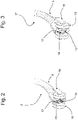
- the cutting head 2 is in detail in the Figures 2 and 3 shown in two different versions. These are largely the same, but differ in the specific design of the cutting element itself.
- the cutting element for cutting through the foil is an arc torch 15, while in the variant according to FIG figure 3 the cutting element consists of fixed knives 15*.
- the respective cutting element 15 is arranged between two opposite rollers 16 as a contact element and opposite the film contact plane 20 formed by the opposite rollers 16 (cf. figure 4 ) set back to form a cutting cavity 17.
- rollers 16 and cutting element 15 are attached to a housing 18 which provides the spaced axes for the rollers 16 and the clearance for the cutting cavity 17.
- the housing 18 is connected to the end facing away from the cutting cavity 17 with the vacuum hose 9, so that the cutting cavity 17 has a grid-like Suction port 19 is connected to the vacuum pump 14 for sucking the portion of the film wrap to be cut locally into the cutting cavity 17 for interaction with the cutting element.
- the respective cutting element 15 is arranged centrally on the grid of the suction opening 19 . Suction openings are therefore arranged around the respective cutting element 15 .
- the pallet 3B with the wrapped stack 3A is positioned below the portal 6 on the staging area 4 on the conveyor 5.
- the cutting head 2 is positioned at the upper edge of the stack 3A and moved up to the foil via the support arm 7 or carriage 13 .
- the vacuum is then applied to the cutting head 2 via the pump 14 and the cutting element 15 cuts through the film when the head 2 is moved down.
- the contact force of the cutting head 2 is constantly checked and adjusted via the torque monitor 21 and the controller 10, so that it is in contact despite the irregular contour.
- the cutting element 15 is opened if necessary (arc burner), but the vacuum is left and the support arm 7 is now pivoted around the stack 3A via the rotating device, so that the film is pulled off.
Landscapes
- Engineering & Computer Science (AREA)
- Mechanical Engineering (AREA)
- Life Sciences & Earth Sciences (AREA)
- Forests & Forestry (AREA)
- Auxiliary Devices For And Details Of Packaging Control (AREA)
- Basic Packing Technique (AREA)
Abstract
Description
- Die Erfindung betrifft eine Vorrichtung und ein Verfahren zum automatischen Entfernen einer Folienumwicklung von palettierten Produktstapeln nach Anspruch 1.
- Zur Ladungssicherung werden auf Paletten gestapelte Produkte nach dem Bilden des Stapels häufig mit Stretchfolie umwickelt oder mit einer Schrumpfhauben-Folierung versehen, so dass die Produkte nicht beim Transport verrutschen.
- Allerdings ist es schwierig diese Folienumwicklung später beim Entpacken zu entfernen. Daher wird dies häufig noch manuell durchgeführt.
-
EP 0 720 564 A1 beschreibt eine Vorrichtung und ein Verfahren, bei dem zum Entfernen einer über einen Gutstapel gezogenen Folienhaube, bei dem die Folienhaube an einer Seite des Gutstapels vertikal aufgeschnitten wird, eine Schnittkante erfasst und an einem Wickeldorn befestigt wird sowie anschließend der Wickeldorn um den Gutstapel herumgeführt und dabei die Folie auf den sich um seine Längsachse drehenden Wickeldorn aufgewickelt wird. Dazu wird über ein Messer die Folie vertikal geschnitten und dabei über eine Saugvorrichtung vom Stapel bereichsweise abgehoben. - Aus
US 2004/0099110 A1 ist es bekannt auf gegenüberliegenden Seiten des umwickelten Stapels entsprechende Vorrichtungen anzuordnen, die analogEP 0 720 564 A1 auf beiden Seiten gleichzeitig schneiden. - Diese Vorrichtungen können schon im Prinzip automatisiert mit Folie umwickelte homogene Paletten bearbeiten.
- Allerdings besteht gerade für inhomogen oder gemischt bestapelte Paletten noch Bedarf nach besser funktionierenden Mechanismen, da diese aufgrund der ungleichmäßigen Kontur bisher nicht gut bearbeitbar sind.
- Demgegenüber besteht die Aufgabe der vorliegenden Erfindung darin, eine verbesserte Alternative bereitzustellen, die insbesondere bei inhomogen oder gemischt bestapelten Paletten besser funktioniert.
- Diese Aufgabe wird durch den in Anspruch 1 wiedergegebenen Schneidkopf und der in Anspruch 7 angegebenen Vorrichtung gelöst. Vorteilhafte Ausgestaltungen ergeben sich aus den Unteransprüchen und der Beschreibung.
- Erfindungsgemäß ist erkannt worden, dass wenn der Schneidkopf zum Auftrennen einer Folienumwicklung von palettierten Produktstapeln mit einem Schneidelement zum Durchtrennen der Folie ausgestaltet ist, wobei das Schneidelement zwischen mindestens zwei gegenüberliegenden Kontaktelementen angeordnet ist und gegenüber der von den gegenüberliegenden Kontaktelementen ausgebildeten Folienanlageebene zur Ausbildung einer Schneidhöhle zurückversetzt ist, und mit einer Vakuumeinheit zum Ansaugen des lokal zu schneidenden Bereichs der Folienumwicklung in die Schneidhöhle zur Wechselwirkung mit dem Schneidelement, es möglich ist, sowohl manuell als auch automatisiert, den Schneidkopf immer auf der Oberfläche des mit Folie umwickelten Stapels entlangzuführen und die Folie nur im Bereich des Schneidelements abzuheben, sodass eine sichere und zuverlässige Auftrennung erreicht wird.
- Mit anderen Worten, der Schneidkopf ist beim Auftrennen immer über die Kontaktelemente in Kontakt mit der Folienoberfläche des Stapels.
- Dies ist insbesondere wichtig bei gemischten Stapeln, also Stapeln aus unterschiedlichen Artikeln, da diese eine unregelmäßige Außenkontur ausbilden und die Folie somit ebenfalls eine unregelmäßige Kontur ausbildet und der Kontakt eine sichere und zuverlässige Auftrennung ermöglicht.
- Die zurückversetzte Schneidhöhle verbirgt das Schneidwerkzeug bzw. Schneidelement vor zufälligen Berührungen.
- Vorzugsweise sind die Kontaktelemente als Gleitelemente und/oder Abrollelemente ausgebildet. Die Gleitelemente können z. B. Gleitkufen sein, die beispielsweise eine reibungsvermindernde Oberfläche aufweisen. Dies ist von Vorteil, da die Folien häufig "klebrig" sind.
- Die Abrollelemente können z. B. Rollen sein.
- Denkbar ist auch die Verwendung von mehr als zwei gegenüberliegenden Kontaktelementen. So kann es vorteilhaft sein, die Schneidhöhle zwischen zwei Paaren von gegenüberliegenden Kontaktelementen anzuordnen. Dann kann der Schneidkopf weniger leicht kippen, da er an vier Punkten geführt wird.
- Zum eigentlichen Auftrennen der Folie weist der Schneidkopf ein Schneidelement auf. Das Schneidelement kann beispielsweise ein starres oder rotierendes Messer, ein Glühdraht oder ein Lichtbogenbrenner sein. Bevorzugt ist der Lichtbogenbrenner, da dieser besonders zuverlässig alle Arten von Folien schneidet.
- Erfindungsgemäß wird die Folie beim Auftrennen mit einer Vakuumeinheit nur lokal in die Schneidhöhle zur Wechselwirkung mit dem Schneidelement angesaugt. Die Vakuumeinheit kann dazu mindestens eine Ansaugöffnung aufweisen, neben der das Schneidelement platziert ist. Vorzugsweise können auch zwei (oder mehr) Ansaugöffnungen vorgesehen sein, zwischen denen das Schneidelement (ggf. zentral) angeordnet ist.
- Die Erfindung betrifft auch den Einsatz mindestens eines entsprechenden Schneidkopfes in einer automatisierten Vorrichtung mit einem Palettenplatz für die Anordnung der entsprechend mit Folie umwickelten Palette, wobei der Schneidkopf an einem Ende eines derart verfahrbaren Tragarms angeordnet ist, dass der Schneidkopf immer über den zwei gegenüberliegenden Kontaktelementen in Anlage an der Folie beim Schneiden ist.
- In einer bevorzugten Ausführungsform ist der Tragarm sowohl vertikal als auch horizontal motorisch über eine Steuerung gesteuert derart verfahrbar ausgebildet, dass der Schneidkopf immer beim Schneiden an der Folie anliegt. Dies hat insbesondere den Vorteil, dass der Tragarm den Schneidkopf über die mehrfache Beweglichkeit immer in Kontakt mit der Folie auch bei unregelmäßiger Kontur halten kann.
- Dazu kann die Steuerung eine Einrichtung aufweisen, die die Andruckkraft des Schneidkopfes an der Folie bestimmt und eine Regelung zulässt.
- Die Einrichtung kann z. B. einen taktilen Sensor aufweisen, dessen Daten in die Steuerung eingespeist werden, um eine Regelung zu erlauben. Alternativ oder zusätzlich kann der motorische Antrieb des Tragarms eine Drehmomentüberwachung aufweisen, deren Daten in die Steuerung eingespeist werden, um eine Regelung zu erlauben.
- Die Vorrichtung kann verschiedenste Ausgestaltungen aufweisen. In einer bevorzugten Ausführungsform ist die Vorrichtung portalartig ausgebildet, so dass der Tragarm Bestandteil eines Portalgestells ist, an dem der Tragarm dann motorisch beweglich verstellbar ist, wobei der Palettenbereitstellplatz auf einem Förderer angeordnet ist, der durch das Portal verläuft. Alternativ kann der Tragarm auch als Teil eines Mehrachsen-Industrieroboters ausgebildet sein.
- Es versteht sich, dass der Begriff Palette auch andere ähnliche Ladehilfsmittel umfasst.
- Weitere Details der Erfindung ergeben sich aus der nachfolgenden Beschreibung von Ausführungsbeispielen anhand der Zeichnung, in der
- Fig. 1
- eine schematische perspektivische Ansicht einer automatisierten Vorrichtung mit einem Schneidkopf zum automatischen Entfernen einer Folienumwicklung von palettierten Produktstapeln;
- Fig. 2
- eine schematische perspektivische Ansicht eines ersten erfindungsgemäßen Schneidkopfes zum Auftrennen einer Folienumwicklung, insbesondere in einer Vorrichtung nach
Figur 1 ; und - Fig. 3
- eine schematische perspektivische Ansicht eines weiteren erfindungsgemäßen Schneidkopfes zum Auftrennen einer Folienumwicklung, insbesondere in einer Vorrichtung nach
Figur 1 ; und - Fig. 4
- eine Schnittansicht durch den Schneidkopf aus
Figur 3 zeigen. - In
Figur 1 ist eine als Ganzes mit 1 bezeichnete Vorrichtung zum automatischen Entfernen einer Folienumwicklung von palettierten Produktstapeln gezeigt. - Die Vorrichtung weist dazu einen Schneidkopf 2 zum Auftrennen der Folie auf, die um einen Stapel 3A auf einer Palette 3B gewickelt ist.
- Die Palette 3B mit dem umwickelten Stapel 3A wird auf einem Palettenplatz 4 für die Anordnung bereitgestellt, der auf einem Rollenförderer 5 liegt, der durch das Portalgestell 6 der Vorrichtung führt.
- Der Schneidkopf 2 ist an einem Ende eines L-förmigen Tragarms 7 derart an einem Schlitten 13 verfahrbar angeordnet, dass er sowohl vertikal als auch horizontal motorisch über eine Steuerung 10 gesteuert derart verfahrbar ausgebildet ist, dass der Schneidkopf 2 immer beim Schneiden an der Folie anliegt. Dies ist über die Pfeile 11, 12 angedeutet. Zusätzlich ist der Tragarm 7 über eine Drehvorrichtung 8 an dem Portalkopf angelenkt, so dass der gesamte Tragarm 7 um die Palette 3B bzw. Stapel 3A herum schwenkbar ist, um z. B. die durchtrennte Folie zum Abschluss zu entfernen.
- Die motorische Verstellung des Schlittens 13 weist eine Drehmomentüberwachung 21 auf, die die Steuerung 10 mit Daten zur Anlagekraft des Schneidkopfes 2 speist, so dass das Anliegen geregelt werden kann.
- Vom Schneidkopf 2 entlang des Tragarms 7 bis zur Drehvorrichtung 8 verläuft ein Vakuumschlauch 9, der von einer Pumpe 14 beaufschlagt wird, die in der Drehvorrichtung 8 aufgenommen und ebenfalls von der Steuerung 10 geregelt wird.
- Der Schneidkopf 2 ist im Detail in den
Figuren 2 und 3 in zwei unterschiedlichen Varianten gezeigt. Diese stimmen weitestgehend überein, unterscheiden sich aber in der konkreten Ausgestaltung des Schneidelements selbst. - In
Figur 2 ist das Schneidelement zum Durchtrennen der Folie ein Lichtbogenbrenner 15, während in der Variante nachFigur 3 das Schneidelement aus feststehenden Messern 15* besteht. - Das jeweilige Schneidelement 15 ist zwischen zwei gegenüberliegenden Rollen 16 als Kontaktelement angeordnet und gegenüber der von den gegenüberliegenden Rollen 16 ausgebildeten Folienanlageebene 20 (vgl.
Figur 4 ) zur Ausbildung einer Schneidhöhle 17 zurückversetzt. - Die Rollen 16 und das Schneidelement 15 sind an einem Gehäuse 18 befestigt, das die beabstandeten Achsen für die Rollen 16 bereitstellt und den Zwischenraum für die Schneidhöhle 17.
- Das Gehäuse 18 ist an dem der Schneidhöhle 17 abgewandten Ende mit dem Vakuumschlauch 9 verbunden, so dass die Schneidhöhle 17 über eine gitterartige Ansaugöffnung 19 mit der Vakuumpumpe 14 zum Ansaugen des lokal zu schneidenden Bereichs der Folienumwicklung in die Schneidhöhle 17 zur Wechselwirkung mit dem Schneidelement verbunden ist.
- Das jeweilige Schneidelement 15 ist dabei zentral auf dem Gitter der Ansaugöffnung 19 angeordnet. Ansaugöffnungen sind also um das jeweilige Schneidelement 15 herum angeordnet.
- Zum Auftrennen der Folienumwicklung wird also zunächst die Palette 3B mit dem umwickelten Stapel 3A unterhalb des Portals 6 auf dem Bereitstellungsplatz 4 auf dem Förderer 5 positioniert.
- Dann wird der Schneidkopf 2 an der oberen Kante des Stapels 3A positioniert und über den Tragarm 7 bzw. Schlitten 13 an die Folie herangefahren.
- Anschließend wird das Vakuum über die Pumpe 14 an den Schneidkopf 2 angelegt und das Schneidelement 15 durchtrennt beim Herabbewegen des Kopfes 2 die Folie.
- Dabei wird über die Drehmomentüberwachung 21 und die Steuerung 10 ständig die Anlagekraft des Schneidkopfes 2 geprüft und eingestellt, so dass dieser trotz unregelmäßiger Kontur anliegt.
- Unten angekommen, d. h. nach Auftrennung der gesamten Folie, wird ggf. das Schneidelement 15 ausgestellt (Lichtbogenbrenner), aber das Vakuum belassen und der Tragarm 7 nun über die Drehvorrichtung um den Stapel 3A herum verschwenkt, so dass die Folie abgezogen wird.
- Letztendlich wird dann die entfernte Folie der Entsorgung zugeführt.
Claims (11)
- Schneidkopf zum Auftrennen einer Folienumwicklung von palettierten Produktstapeln mit einem Schneidelement zum Durchtrennen der Folie, wobei das Schneidelement zwischen mindestens zwei gegenüberliegenden Kontaktelementen angeordnet ist und gegenüber der von den gegenüberliegenden Kontaktelementen ausgebildeten Folienanlageebene zur Ausbildung einer Schneidhöhle zurückversetzt ist, und mit einer Vakuumeinheit zum Ansaugen des lokal zu schneidenden Bereichs der Folienumwicklung in die Schneidhöhle zur Wechselwirkung mit dem Schneidelement.
- Schneidkopf nach Anspruch 1, dadurch gekennzeichnet, dass die Kontaktelemente Gleitelemente und/oder Abrollelemente sind.
- Schneidkopf nach Anspruch 2, dadurch gekennzeichnet, dass die Gleitelemente Gleitkufen sind.
- Schneidkopf nach Anspruch 2, dadurch gekennzeichnet, dass die Abrollelemente Rollen sind.
- Schneidkopf nach einem der vorhergehenden Ansprüche, dadurch gekennzeichnet, dass das Schneidelement ein starres oder rotierendes Messer, einen Glühdraht oder einen Lichtbogenbrenner aufweist.
- Schneidkopf nach einem der vorhergehenden Ansprüche, dadurch gekennzeichnet, dass die Vakuumeinheit mindestens eine Ansaugöffnung aufweist, neben der das Schneidelement platziert ist.
- Vorrichtung zum automatischen Entfernen einer Folienumwicklung von palettierten Produktstapeln mit mindestens einem Schneidkopf nach einem der vorhergehenden Ansprüche, und einem Palettenplatz für die Anordnung der entsprechend mit Folie umwickelten Palette, wobei der Schneidkopf an einem Ende eines derart verfahrbaren Tragarms angeordnet ist, dass der Schneidkopf immer über den zwei gegenüberliegenden Kontaktelementen in Anlage an der Folie beim Schneiden ist.
- Vorrichtung nach Anspruch 7, dadurch gekennzeichnet, dass der Tragarm sowohl vertikal als auch horizontal motorisch über eine Steuerung gesteuert derart verfahrbar ausgebildet ist, dass der Schneidkopf immer beim Schneiden an der Folie anliegt.
- Vorrichtung nach Anspruch 8, dadurch gekennzeichnet, dass die Steuerung über einen taktilen Sensor am Tragarm mit Daten zur Anpresskraft gespeist wird.
- Vorrichtung nach Anspruch 8 oder 9, dadurch gekennzeichnet, dass der motorische Antrieb des Tragarms eine Kraft- oder Drehmomentüberwachung aufweist, die die Steuerung mit Daten zur Anpresskraft speist.
- Vorrichtung nach einem der vorhergehenden Ansprüche 7 bis 10, dadurch gekennzeichnet, dass der Tragarm Bestandteil eines Portalgestells oder Industrieroboters ist.
Applications Claiming Priority (1)
| Application Number | Priority Date | Filing Date | Title |
|---|---|---|---|
| DE102021107386.3A DE102021107386A1 (de) | 2021-03-24 | 2021-03-24 | Vorrichtung und Verfahren zum automatischen Entfernen einer Folienumwicklung von palettierten Produktstapeln |
Publications (3)
| Publication Number | Publication Date |
|---|---|
| EP4063284A1 true EP4063284A1 (de) | 2022-09-28 |
| EP4063284C0 EP4063284C0 (de) | 2023-11-29 |
| EP4063284B1 EP4063284B1 (de) | 2023-11-29 |
Family
ID=80787340
Family Applications (1)
| Application Number | Title | Priority Date | Filing Date |
|---|---|---|---|
| EP22162766.4A Active EP4063284B1 (de) | 2021-03-24 | 2022-03-17 | Vorrichtung zum entfernen einer folienumwicklung von palettierten produktstapeln |
Country Status (3)
| Country | Link |
|---|---|
| US (1) | US12492033B2 (de) |
| EP (1) | EP4063284B1 (de) |
| DE (1) | DE102021107386A1 (de) |
Families Citing this family (2)
| Publication number | Priority date | Publication date | Assignee | Title |
|---|---|---|---|---|
| EP4357261A1 (de) * | 2022-10-21 | 2024-04-24 | Tetra Laval Holdings & Finance S.A. | System und verfahren zur handhabung einer beutelanordnung |
| IT202300013731A1 (it) * | 2023-06-30 | 2024-12-30 | E2Pack S R L | Dispositivo di taglio per la svestizione di un pallet |
Citations (6)
| Publication number | Priority date | Publication date | Assignee | Title |
|---|---|---|---|---|
| EP0720564A1 (de) | 1993-09-23 | 1996-07-10 | Msk Verpackung Syst Gmbh | Verfahren und vorrichtung zum entfernen einer über einen gutstapel gezogenen folienhaube |
| DE19724040A1 (de) * | 1996-10-17 | 1998-08-20 | Daimler Benz Ag | Verfahren und Vorrichtung zum Durchtrennen von Schutzfolie im Bereich überklebter Fugen und Sicken von Karosserien |
| US20040099110A1 (en) | 2000-07-31 | 2004-05-27 | Mauro Cere | Apparatus for removing plastic wrapping film from pallets of products |
| EP1935524A1 (de) * | 2006-12-21 | 2008-06-25 | Linde Aktiengesellschaft | Vorrichtung zum Flammrichten |
| DE102014003652A1 (de) * | 2014-03-13 | 2015-09-17 | Giesecke & Devrient Gmbh | Verfahren und Vorrichtung zum Öffnen eines Behälters |
| DE102018216534A1 (de) * | 2018-09-27 | 2020-04-02 | Bayerische Motoren Werke Aktiengesellschaft | Schneidvorrichtung sowie Verfahren zum Schneiden einer Maskierung eines Kraftfahrzeugbauteils |
Family Cites Families (12)
| Publication number | Priority date | Publication date | Assignee | Title |
|---|---|---|---|---|
| JPS57140990U (de) * | 1981-02-28 | 1982-09-03 | ||
| US4488466A (en) * | 1982-09-07 | 1984-12-18 | Seal Tech Corp. | Apparatus for cutting sheet material |
| JPH02166034A (ja) * | 1988-12-21 | 1990-06-26 | Kirin Brewery Co Ltd | 包装材切開除去装置 |
| DE4212095C1 (de) | 1992-04-10 | 1993-08-19 | Man Roland Druckmaschinen Ag, 6050 Offenbach, De | |
| DE4311421A1 (de) | 1993-04-07 | 1994-10-13 | Vfi Verpackungstech | Verfahren und Vorrichtung zum Entfernen einer sichernden und/oder schützenden Folie |
| JP2670980B2 (ja) | 1994-07-04 | 1997-10-29 | 王子製袋株式会社 | フィルム包装体の開梱装置 |
| NL1028794C2 (nl) | 2005-04-18 | 2006-10-20 | Celema B V | Inrichting en werkwijze voor het openen van een kunststoffen verpakking van een stapel blikdeksels. |
| JP6006951B2 (ja) * | 2012-03-22 | 2016-10-12 | 日本発條株式会社 | 板材の切断装置 |
| US10647102B2 (en) * | 2017-07-06 | 2020-05-12 | General Electric Company | System and method for removal of a layer |
| US11905048B2 (en) * | 2018-06-22 | 2024-02-20 | Signode Industrial Group Llc | Wrapping machine with a roping assembly |
| ES2946013T3 (es) * | 2018-12-04 | 2023-07-11 | Aetna Group Spa | Método y aparato para envolver una carga y máquina de envolver |
| WO2021165491A1 (en) | 2020-02-20 | 2021-08-26 | Varo Specialmaskiner A/S | Unwrapping apparatus and method for unwrapping articles |
-
2021
- 2021-03-24 DE DE102021107386.3A patent/DE102021107386A1/de not_active Ceased
-
2022
- 2022-03-17 US US17/697,595 patent/US12492033B2/en active Active
- 2022-03-17 EP EP22162766.4A patent/EP4063284B1/de active Active
Patent Citations (6)
| Publication number | Priority date | Publication date | Assignee | Title |
|---|---|---|---|---|
| EP0720564A1 (de) | 1993-09-23 | 1996-07-10 | Msk Verpackung Syst Gmbh | Verfahren und vorrichtung zum entfernen einer über einen gutstapel gezogenen folienhaube |
| DE19724040A1 (de) * | 1996-10-17 | 1998-08-20 | Daimler Benz Ag | Verfahren und Vorrichtung zum Durchtrennen von Schutzfolie im Bereich überklebter Fugen und Sicken von Karosserien |
| US20040099110A1 (en) | 2000-07-31 | 2004-05-27 | Mauro Cere | Apparatus for removing plastic wrapping film from pallets of products |
| EP1935524A1 (de) * | 2006-12-21 | 2008-06-25 | Linde Aktiengesellschaft | Vorrichtung zum Flammrichten |
| DE102014003652A1 (de) * | 2014-03-13 | 2015-09-17 | Giesecke & Devrient Gmbh | Verfahren und Vorrichtung zum Öffnen eines Behälters |
| DE102018216534A1 (de) * | 2018-09-27 | 2020-04-02 | Bayerische Motoren Werke Aktiengesellschaft | Schneidvorrichtung sowie Verfahren zum Schneiden einer Maskierung eines Kraftfahrzeugbauteils |
Also Published As
| Publication number | Publication date |
|---|---|
| EP4063284C0 (de) | 2023-11-29 |
| US12492033B2 (en) | 2025-12-09 |
| US20220306332A1 (en) | 2022-09-29 |
| DE102021107386A1 (de) | 2022-09-29 |
| EP4063284B1 (de) | 2023-11-29 |
Similar Documents
| Publication | Publication Date | Title |
|---|---|---|
| EP1890954B2 (de) | Verfahren und vorrichtung zum entpalletieren von gestapelten gebinden | |
| EP3227072B1 (de) | Plattenaufteilanlage zum aufteilen von plattenförmigen werkstücken, sowie verfahren zu deren betrieb | |
| EP4063284B1 (de) | Vorrichtung zum entfernen einer folienumwicklung von palettierten produktstapeln | |
| DE10355544B4 (de) | Verfahren und Vorrichtung für die Übergabe von Zuschnitten aus Umkartons an eine Weiterverarbeitungseinheit | |
| EP1022222B1 (de) | Vorrichtung zum Entfernen von Bindeband von mit Bindeband umreiften Gegenständen, insbesondere Coils | |
| EP1184281A1 (de) | Verfahren und Vorrichtung zum Verpacken von Gegenständen | |
| EP3898134A1 (de) | Greifvorrichtung | |
| DE4234536C2 (de) | Anlage zum Schneiden von Glasscheiben | |
| DE19727591A1 (de) | Verbesserter Bündelbrecher | |
| EP1018408B1 (de) | Planschneidmaschine zum Schneiden von gestapeltem, blattförmigem Gut | |
| EP2719627A1 (de) | Verfahren und Vorrichtung zum Umhüllen eines Gutstapels mit einer Folie | |
| EP0625465A2 (de) | Verfahren und Vorrichtung zum Entfernen einer sichernden und/oder schützenden Folie | |
| DE202022003403U1 (de) | Vorrichtung zum Entpacken einer Palette | |
| DE102009040792A1 (de) | Palettenentstapler | |
| EP0792814A1 (de) | Auspackmaschine für Rollen, insbesondere Druckpapierrollen | |
| WO2023168470A1 (de) | Holzbearbeitungsvorrichtung mit bearbeitungsportal | |
| DE19747480C1 (de) | Maschine zum Schneiden und Schweißen von Kunststoffplatten | |
| DE2518359A1 (de) | Holzbearbeitungs-maschine | |
| EP3696105A1 (de) | Tiefziehverpackungsmaschine mit ausheber für randstreifen | |
| DE19955478B4 (de) | Stretch-Wickler | |
| DE102023133198A1 (de) | Vorrichtung zum Anheben und Bewegen eines Stapels übereinander liegender flacher Produkte | |
| DE102020122006A1 (de) | Vorrichtung zum Durchtrennen wenigstens eines zumindest ein Transportelement auf einem Transportträger haltenden Bands | |
| DE1652759A1 (de) | Stapelvorrichtung | |
| WO2023062054A1 (de) | Vorrichtung zum aufschneiden und entfernen einer umreifung | |
| DE19607537C1 (de) | Auspackmaschine für Rollen, insbesondere Druckpapierrollen |
Legal Events
| Date | Code | Title | Description |
|---|---|---|---|
| PUAI | Public reference made under article 153(3) epc to a published international application that has entered the european phase |
Free format text: ORIGINAL CODE: 0009012 |
|
| STAA | Information on the status of an ep patent application or granted ep patent |
Free format text: STATUS: THE APPLICATION HAS BEEN PUBLISHED |
|
| AK | Designated contracting states |
Kind code of ref document: A1 Designated state(s): AL AT BE BG CH CY CZ DE DK EE ES FI FR GB GR HR HU IE IS IT LI LT LU LV MC MK MT NL NO PL PT RO RS SE SI SK SM TR |
|
| STAA | Information on the status of an ep patent application or granted ep patent |
Free format text: STATUS: REQUEST FOR EXAMINATION WAS MADE |
|
| 17P | Request for examination filed |
Effective date: 20230201 |
|
| RBV | Designated contracting states (corrected) |
Designated state(s): AL AT BE BG CH CY CZ DE DK EE ES FI FR GB GR HR HU IE IS IT LI LT LU LV MC MK MT NL NO PL PT RO RS SE SI SK SM TR |
|
| GRAP | Despatch of communication of intention to grant a patent |
Free format text: ORIGINAL CODE: EPIDOSNIGR1 |
|
| STAA | Information on the status of an ep patent application or granted ep patent |
Free format text: STATUS: GRANT OF PATENT IS INTENDED |
|
| INTG | Intention to grant announced |
Effective date: 20230714 |
|
| GRAS | Grant fee paid |
Free format text: ORIGINAL CODE: EPIDOSNIGR3 |
|
| GRAA | (expected) grant |
Free format text: ORIGINAL CODE: 0009210 |
|
| STAA | Information on the status of an ep patent application or granted ep patent |
Free format text: STATUS: THE PATENT HAS BEEN GRANTED |
|
| AK | Designated contracting states |
Kind code of ref document: B1 Designated state(s): AL AT BE BG CH CY CZ DE DK EE ES FI FR GB GR HR HU IE IS IT LI LT LU LV MC MK MT NL NO PL PT RO RS SE SI SK SM TR |
|
| REG | Reference to a national code |
Ref country code: GB Ref legal event code: FG4D Free format text: NOT ENGLISH |
|
| REG | Reference to a national code |
Ref country code: CH Ref legal event code: EP |
|
| REG | Reference to a national code |
Ref country code: DE Ref legal event code: R096 Ref document number: 502022000290 Country of ref document: DE |
|
| REG | Reference to a national code |
Ref country code: IE Ref legal event code: FG4D Free format text: LANGUAGE OF EP DOCUMENT: GERMAN |
|
| U01 | Request for unitary effect filed |
Effective date: 20231201 |
|
| U07 | Unitary effect registered |
Designated state(s): AT BE BG DE DK EE FI FR IT LT LU LV MT NL PT SE SI Effective date: 20231207 |
|
| PG25 | Lapsed in a contracting state [announced via postgrant information from national office to epo] |
Ref country code: GR Free format text: LAPSE BECAUSE OF FAILURE TO SUBMIT A TRANSLATION OF THE DESCRIPTION OR TO PAY THE FEE WITHIN THE PRESCRIBED TIME-LIMIT Effective date: 20240301 |
|
| PG25 | Lapsed in a contracting state [announced via postgrant information from national office to epo] |
Ref country code: IS Free format text: LAPSE BECAUSE OF FAILURE TO SUBMIT A TRANSLATION OF THE DESCRIPTION OR TO PAY THE FEE WITHIN THE PRESCRIBED TIME-LIMIT Effective date: 20240329 |
|
| PG25 | Lapsed in a contracting state [announced via postgrant information from national office to epo] |
Ref country code: ES Free format text: LAPSE BECAUSE OF FAILURE TO SUBMIT A TRANSLATION OF THE DESCRIPTION OR TO PAY THE FEE WITHIN THE PRESCRIBED TIME-LIMIT Effective date: 20231129 |
|
| PG25 | Lapsed in a contracting state [announced via postgrant information from national office to epo] |
Ref country code: IS Free format text: LAPSE BECAUSE OF FAILURE TO SUBMIT A TRANSLATION OF THE DESCRIPTION OR TO PAY THE FEE WITHIN THE PRESCRIBED TIME-LIMIT Effective date: 20240329 Ref country code: GR Free format text: LAPSE BECAUSE OF FAILURE TO SUBMIT A TRANSLATION OF THE DESCRIPTION OR TO PAY THE FEE WITHIN THE PRESCRIBED TIME-LIMIT Effective date: 20240301 Ref country code: ES Free format text: LAPSE BECAUSE OF FAILURE TO SUBMIT A TRANSLATION OF THE DESCRIPTION OR TO PAY THE FEE WITHIN THE PRESCRIBED TIME-LIMIT Effective date: 20231129 |
|
| U20 | Renewal fee for the european patent with unitary effect paid |
Year of fee payment: 3 Effective date: 20240325 |
|
| PG25 | Lapsed in a contracting state [announced via postgrant information from national office to epo] |
Ref country code: RS Free format text: LAPSE BECAUSE OF FAILURE TO SUBMIT A TRANSLATION OF THE DESCRIPTION OR TO PAY THE FEE WITHIN THE PRESCRIBED TIME-LIMIT Effective date: 20231129 Ref country code: PL Free format text: LAPSE BECAUSE OF FAILURE TO SUBMIT A TRANSLATION OF THE DESCRIPTION OR TO PAY THE FEE WITHIN THE PRESCRIBED TIME-LIMIT Effective date: 20231129 Ref country code: NO Free format text: LAPSE BECAUSE OF FAILURE TO SUBMIT A TRANSLATION OF THE DESCRIPTION OR TO PAY THE FEE WITHIN THE PRESCRIBED TIME-LIMIT Effective date: 20240229 Ref country code: HR Free format text: LAPSE BECAUSE OF FAILURE TO SUBMIT A TRANSLATION OF THE DESCRIPTION OR TO PAY THE FEE WITHIN THE PRESCRIBED TIME-LIMIT Effective date: 20231129 |
|
| PG25 | Lapsed in a contracting state [announced via postgrant information from national office to epo] |
Ref country code: CZ Free format text: LAPSE BECAUSE OF FAILURE TO SUBMIT A TRANSLATION OF THE DESCRIPTION OR TO PAY THE FEE WITHIN THE PRESCRIBED TIME-LIMIT Effective date: 20231129 |
|
| PG25 | Lapsed in a contracting state [announced via postgrant information from national office to epo] |
Ref country code: SK Free format text: LAPSE BECAUSE OF FAILURE TO SUBMIT A TRANSLATION OF THE DESCRIPTION OR TO PAY THE FEE WITHIN THE PRESCRIBED TIME-LIMIT Effective date: 20231129 |
|
| PG25 | Lapsed in a contracting state [announced via postgrant information from national office to epo] |
Ref country code: SM Free format text: LAPSE BECAUSE OF FAILURE TO SUBMIT A TRANSLATION OF THE DESCRIPTION OR TO PAY THE FEE WITHIN THE PRESCRIBED TIME-LIMIT Effective date: 20231129 Ref country code: SK Free format text: LAPSE BECAUSE OF FAILURE TO SUBMIT A TRANSLATION OF THE DESCRIPTION OR TO PAY THE FEE WITHIN THE PRESCRIBED TIME-LIMIT Effective date: 20231129 Ref country code: RO Free format text: LAPSE BECAUSE OF FAILURE TO SUBMIT A TRANSLATION OF THE DESCRIPTION OR TO PAY THE FEE WITHIN THE PRESCRIBED TIME-LIMIT Effective date: 20231129 Ref country code: CZ Free format text: LAPSE BECAUSE OF FAILURE TO SUBMIT A TRANSLATION OF THE DESCRIPTION OR TO PAY THE FEE WITHIN THE PRESCRIBED TIME-LIMIT Effective date: 20231129 |
|
| REG | Reference to a national code |
Ref country code: DE Ref legal event code: R097 Ref document number: 502022000290 Country of ref document: DE |
|
| PLBE | No opposition filed within time limit |
Free format text: ORIGINAL CODE: 0009261 |
|
| STAA | Information on the status of an ep patent application or granted ep patent |
Free format text: STATUS: NO OPPOSITION FILED WITHIN TIME LIMIT |
|
| 26N | No opposition filed |
Effective date: 20240830 |
|
| PG25 | Lapsed in a contracting state [announced via postgrant information from national office to epo] |
Ref country code: MC Free format text: LAPSE BECAUSE OF FAILURE TO SUBMIT A TRANSLATION OF THE DESCRIPTION OR TO PAY THE FEE WITHIN THE PRESCRIBED TIME-LIMIT Effective date: 20231129 |
|
| PG25 | Lapsed in a contracting state [announced via postgrant information from national office to epo] |
Ref country code: MC Free format text: LAPSE BECAUSE OF FAILURE TO SUBMIT A TRANSLATION OF THE DESCRIPTION OR TO PAY THE FEE WITHIN THE PRESCRIBED TIME-LIMIT Effective date: 20231129 |
|
| PG25 | Lapsed in a contracting state [announced via postgrant information from national office to epo] |
Ref country code: IE Free format text: LAPSE BECAUSE OF NON-PAYMENT OF DUE FEES Effective date: 20240317 |
|
| PG25 | Lapsed in a contracting state [announced via postgrant information from national office to epo] |
Ref country code: IE Free format text: LAPSE BECAUSE OF NON-PAYMENT OF DUE FEES Effective date: 20240317 |
|
| U20 | Renewal fee for the european patent with unitary effect paid |
Year of fee payment: 4 Effective date: 20250325 |
|
| PG25 | Lapsed in a contracting state [announced via postgrant information from national office to epo] |
Ref country code: CY Free format text: LAPSE BECAUSE OF FAILURE TO SUBMIT A TRANSLATION OF THE DESCRIPTION OR TO PAY THE FEE WITHIN THE PRESCRIBED TIME-LIMIT; INVALID AB INITIO Effective date: 20220317 |
|
| REG | Reference to a national code |
Ref country code: CH Ref legal event code: H13 Free format text: ST27 STATUS EVENT CODE: U-0-0-H10-H13 (AS PROVIDED BY THE NATIONAL OFFICE) Effective date: 20251023 |
|
| PG25 | Lapsed in a contracting state [announced via postgrant information from national office to epo] |
Ref country code: TR Free format text: LAPSE BECAUSE OF FAILURE TO SUBMIT A TRANSLATION OF THE DESCRIPTION OR TO PAY THE FEE WITHIN THE PRESCRIBED TIME-LIMIT Effective date: 20231129 |
|
| PG25 | Lapsed in a contracting state [announced via postgrant information from national office to epo] |
Ref country code: CH Free format text: LAPSE BECAUSE OF NON-PAYMENT OF DUE FEES Effective date: 20250331 |
|
| U20 | Renewal fee for the european patent with unitary effect paid |
Year of fee payment: 5 Effective date: 20260326 |