EP4062829A1 - Vorrichtung zur beobachtung von körperflüssigkeiten - Google Patents
Vorrichtung zur beobachtung von körperflüssigkeiten Download PDFInfo
- Publication number
- EP4062829A1 EP4062829A1 EP20896079.9A EP20896079A EP4062829A1 EP 4062829 A1 EP4062829 A1 EP 4062829A1 EP 20896079 A EP20896079 A EP 20896079A EP 4062829 A1 EP4062829 A1 EP 4062829A1
- Authority
- EP
- European Patent Office
- Prior art keywords
- chamber
- body fluid
- observation device
- horizontal direction
- main body
- Prior art date
- Legal status (The legal status is an assumption and is not a legal conclusion. Google has not performed a legal analysis and makes no representation as to the accuracy of the status listed.)
- Pending
Links
- 210000001124 body fluid Anatomy 0.000 title claims abstract description 125
- 239000010839 body fluid Substances 0.000 title claims abstract description 125
- 238000003780 insertion Methods 0.000 claims abstract description 48
- 230000037431 insertion Effects 0.000 claims abstract description 48
- 238000005192 partition Methods 0.000 claims abstract description 44
- 230000008878 coupling Effects 0.000 claims description 51
- 238000010168 coupling process Methods 0.000 claims description 51
- 238000005859 coupling reaction Methods 0.000 claims description 51
- 239000000758 substrate Substances 0.000 claims description 36
- 230000005540 biological transmission Effects 0.000 claims description 7
- 230000002265 prevention Effects 0.000 claims description 7
- 239000004020 conductor Substances 0.000 claims description 3
- 238000000034 method Methods 0.000 description 6
- 238000004891 communication Methods 0.000 description 4
- 230000008859 change Effects 0.000 description 3
- 239000000126 substance Substances 0.000 description 3
- 230000000694 effects Effects 0.000 description 2
- 229940088597 hormone Drugs 0.000 description 2
- 239000005556 hormone Substances 0.000 description 2
- 238000007689 inspection Methods 0.000 description 2
- 230000005856 abnormality Effects 0.000 description 1
- 230000009471 action Effects 0.000 description 1
- 238000003745 diagnosis Methods 0.000 description 1
- 201000010099 disease Diseases 0.000 description 1
- 208000037265 diseases, disorders, signs and symptoms Diseases 0.000 description 1
- 230000036541 health Effects 0.000 description 1
- 208000015181 infectious disease Diseases 0.000 description 1
- 238000001746 injection moulding Methods 0.000 description 1
- 238000004519 manufacturing process Methods 0.000 description 1
- 239000000203 mixture Substances 0.000 description 1
- 238000012986 modification Methods 0.000 description 1
- 230000004048 modification Effects 0.000 description 1
- 230000016087 ovulation Effects 0.000 description 1
- 210000003296 saliva Anatomy 0.000 description 1
- 230000028327 secretion Effects 0.000 description 1
- 239000004984 smart glass Substances 0.000 description 1
- 239000000243 solution Substances 0.000 description 1
- 210000004243 sweat Anatomy 0.000 description 1
- 210000002700 urine Anatomy 0.000 description 1
Images


Classifications
-
- A—HUMAN NECESSITIES
- A61—MEDICAL OR VETERINARY SCIENCE; HYGIENE
- A61B—DIAGNOSIS; SURGERY; IDENTIFICATION
- A61B5/00—Measuring for diagnostic purposes; Identification of persons
- A61B5/145—Measuring characteristics of blood in vivo, e.g. gas concentration or pH-value ; Measuring characteristics of body fluids or tissues, e.g. interstitial fluid or cerebral tissue
- A61B5/14507—Measuring characteristics of blood in vivo, e.g. gas concentration or pH-value ; Measuring characteristics of body fluids or tissues, e.g. interstitial fluid or cerebral tissue specially adapted for measuring characteristics of body fluids other than blood
-
- A—HUMAN NECESSITIES
- A61—MEDICAL OR VETERINARY SCIENCE; HYGIENE
- A61B—DIAGNOSIS; SURGERY; IDENTIFICATION
- A61B10/00—Instruments for taking body samples for diagnostic purposes; Other methods or instruments for diagnosis, e.g. for vaccination diagnosis, sex determination or ovulation-period determination; Throat striking implements
- A61B10/0012—Ovulation-period determination
-
- A—HUMAN NECESSITIES
- A61—MEDICAL OR VETERINARY SCIENCE; HYGIENE
- A61B—DIAGNOSIS; SURGERY; IDENTIFICATION
- A61B10/00—Instruments for taking body samples for diagnostic purposes; Other methods or instruments for diagnosis, e.g. for vaccination diagnosis, sex determination or ovulation-period determination; Throat striking implements
- A61B10/0045—Devices for taking samples of body liquids
- A61B10/0051—Devices for taking samples of body liquids for taking saliva or sputum samples
-
- A—HUMAN NECESSITIES
- A61—MEDICAL OR VETERINARY SCIENCE; HYGIENE
- A61B—DIAGNOSIS; SURGERY; IDENTIFICATION
- A61B10/00—Instruments for taking body samples for diagnostic purposes; Other methods or instruments for diagnosis, e.g. for vaccination diagnosis, sex determination or ovulation-period determination; Throat striking implements
- A61B10/0045—Devices for taking samples of body liquids
- A61B10/0058—Devices for taking samples of body liquids for taking sperm samples
-
- A—HUMAN NECESSITIES
- A61—MEDICAL OR VETERINARY SCIENCE; HYGIENE
- A61B—DIAGNOSIS; SURGERY; IDENTIFICATION
- A61B5/00—Measuring for diagnostic purposes; Identification of persons
- A61B5/145—Measuring characteristics of blood in vivo, e.g. gas concentration or pH-value ; Measuring characteristics of body fluids or tissues, e.g. interstitial fluid or cerebral tissue
- A61B5/1455—Measuring characteristics of blood in vivo, e.g. gas concentration or pH-value ; Measuring characteristics of body fluids or tissues, e.g. interstitial fluid or cerebral tissue using optical sensors, e.g. spectral photometrical oximeters
-
- G—PHYSICS
- G01—MEASURING; TESTING
- G01N—INVESTIGATING OR ANALYSING MATERIALS BY DETERMINING THEIR CHEMICAL OR PHYSICAL PROPERTIES
- G01N33/00—Investigating or analysing materials by specific methods not covered by groups G01N1/00 - G01N31/00
- G01N33/48—Biological material, e.g. blood, urine; Haemocytometers
- G01N33/483—Physical analysis of biological material
- G01N33/487—Physical analysis of biological material of liquid biological material
-
- A—HUMAN NECESSITIES
- A61—MEDICAL OR VETERINARY SCIENCE; HYGIENE
- A61B—DIAGNOSIS; SURGERY; IDENTIFICATION
- A61B10/00—Instruments for taking body samples for diagnostic purposes; Other methods or instruments for diagnosis, e.g. for vaccination diagnosis, sex determination or ovulation-period determination; Throat striking implements
- A61B10/0045—Devices for taking samples of body liquids
-
- A—HUMAN NECESSITIES
- A61—MEDICAL OR VETERINARY SCIENCE; HYGIENE
- A61B—DIAGNOSIS; SURGERY; IDENTIFICATION
- A61B10/00—Instruments for taking body samples for diagnostic purposes; Other methods or instruments for diagnosis, e.g. for vaccination diagnosis, sex determination or ovulation-period determination; Throat striking implements
- A61B10/0012—Ovulation-period determination
- A61B2010/0025—Ovulation-period determination based on analysis of crystalisation structure
Definitions
- the present disclosure relates to a body fluid observation device for observing a user's body fluid.
- this procedure requires a long wait to receive an examination, but the actual examination or inspection is conducted in a very short time. That is, it takes a lot of time and money to receive the examination or inspection, which involves a lot of inconvenience.
- the use of a simple tester which has been used for a long time, continues and is increasingly used by the younger generation due to ease of use, low cost, and convenience.
- Such a tester detects biochemical substances such as hormones discharged under particular circumstances by using secretions from people's bodies, e.g., saliva, urine, sweat, etc.
- the tester may be used to detect hormones included in the biochemical substances or to check a change in state of the biochemical substances.
- the tester uses a change in the composition of body fluid or a change in state when the body is subjected to a specific situation, for example, a specific disease, infection, or abnormality or peculiarity of the body such as ovulation.
- the present disclosure provides a body fluid observation device for observing a user's body fluid.
- a body fluid observation device includes: a chamber having a length in a first horizontal direction and having a user's body fluid received therein; and a body into which the chamber is inserted to monitor the body fluid, wherein the body includes a case provided with a chamber insertion hole, into which the chamber is inserted in a front surface of the body, a guide partition extending from the chamber insertion hole in the first horizontal direction to guide the chamber, and an observation hole provided through a bottom surface of the body to allow observation of the body fluid; a light source part positioned above the chamber in the case and emitting light; and an operation part electrically connected to the light source part to operate the light source part, wherein, as the chamber is inserted into the chamber insertion hole, the operation part forms an electric closed loop for operating the light source part.
- the chamber may include a body fluid receiving groove in which a portion for seating the body fluid is received in an upper surface, and, in the chamber, at least the body fluid receiving groove may be transparent or translucent.
- the chamber may have a guide protrusion formed in a lower surface thereof and protruding downward, and the main body may be positioned below the chamber insertion hole and include a guide groove into which the guide protrusion is inserted in the first horizontal direction as the chamber is inserted into the chamber insertion hole.
- the guide partition may extend from an end of the first horizontal direction in a second horizontal direction crossing the first horizontal direction, and a shape of the guide partition extending in the second horizontal direction may correspond to a planar shape at an end of the chamber in the first horizontal direction.
- the planar shape at the end of the first horizontal direction is asymmetric in both sides thereof with respect to a center line parallel to the first horizontal direction
- a shape of the guide partition extending from the guide partition in the second horizontal direction may be asymmetric in both sides thereof with respect to a center line parallel to the first horizontal direction
- the operation part may include an operation switch to be turned on by being pressed by the chamber while the chamber is inserted into the chamber insertion hole, and to form the electric closed loop.
- the operation switch may be located on an extension line of the guide partition.
- the operation part may include: a first substrate provided with a circuit pattern electrically connected to the light source part; and a second substrate located under the first substrate, electrically connected to the first substrate, and provided with the operation switch disposed thereunder, and the operation switch may be fixed to overlap on an extension line of the guide partition under the second substrate.
- the light source part may be located in a central portion of the first substrate, and a light transmission hole through which light emitted from the light source part passes may be provided in a central portion of the second substrate.
- the chamber may include a chamber electrode having an electrode pattern of a conductive material
- the operation part may include a guide electrode located at a portion of the guide partition corresponding to the chamber electrode so as to form the electric closed loop, so that the guide electrode is connected to the chamber electrode upon insertion of the chamber.
- the main body may further include a lens part fixedly coupled to the observation hole of the case to enlarge an image of the body fluid.
- the body fluid observation device may further include a main body holder fitted to an outer surface of the body so as to fix the body to a device having a camera.
- the case of the main body may include a case coupling groove recessed along an outer circumferential surface of the case of the main body so that the main body holder is coupled thereto, and the main body holder may include: a coupling wing portion formed in an arc shape to surround the outer circumferential surface of the case of the main body and to be inserted into the case coupling groove; and a body portion extending from a central portion of the coupling wing portion to be coupled to a user terminal.
- the main body may include: a first locking protrusion protruding from a bottom surface of the case coupling groove at both portions adjacent to the chamber insertion hole in the case coupling groove; and a second locking protrusion provided at a portion on an opposite side to the chamber insertion hole in the case coupling groove.
- the coupling wing portion may include: a first locking groove provided at both ends of the arc, the first locking groove into which the first locking protrusion is inserted; and a second locking groove provided at a central portion of the arc, the second locking groove into which the second locking protrusion is inserted.
- the body holder may include a deformation prevention hole at a portion connected to the body portion in the coupling wing portion.
- an operation part may form an electric closed loop for operating a light source part, so that a user can more conveniently observe body fluid.
- the second horizontal direction refers to a direction crossing or intersecting the first horizontal direction. That is, the second horizontal direction may intersect the first horizontal direction at a right angle, but not necessarily limited thereto, and a range similar to the right angle may be included.
- a vertical direction refers to a direction crossing a horizontal plane formed by the first and second horizontal directions.
- the vertical direction may vertically intersect the first and second horizontal directions, but it is not necessarily limited thereto, and a range similar to a vertical extent may be included.
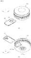
- FIG. 1 shows the overall appearance of the body fluid observation device according to an example of the present disclosure
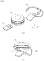
- FIG. 2 illustrates an example in which the main body holder 300 is further coupled to the main body 200 of the body fluid observation device according to an example of the present disclosure
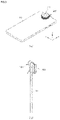
- FIG. 3 is a view for explaining an example in which the body fluid observation device shown in FIG. 2 is coupled to the user terminal 10 and used
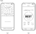
- FIG. 4 is a body fluid observation device coupled to the user terminal 10. When used, it is a view for explaining an example of a body fluid image observed through the user terminal 10.
- a body fluid observation device may include a chamber 100 and a main body 200.
- the chamber 100 has a length in the first horizontal direction x, and the user's body fluid may be received in the chamber 100, and to this end, the chamber 100 may be provided with a body fluid receiving groove 110 in which the user's body fluid is to be received.
- the main body 200 may include a chamber insertion hole H200a into which the chamber 100 is inserted, and an observation hole H200b provided in a bottom surface of the main body 200 to observe the body fluid.
- the chamber 100 having the user's body fluid received therein is inserted into the main body 200 through the chamber insertion hole H200a, the user's body fluid may be observed through the observation hole H200b.
- a lens part 250 may be coupled to the observation hole H200b to observe an enlarged image of the body fluid, and the user may be able to observe the user's body fluid through the observation hole H200b with naked eyes.
- the present disclosure is not necessarily limited thereto, and the body fluid observation device according to an example of the present disclosure may be used in combination with the user terminal 10 provided having a camera.
- a body fluid analysis program or application for analyzing video image information acquired through the body fluid observation device may be installed in the user terminal 10.
- the user terminal 10 may include any wired or wireless communication device capable of communication, and may include a mobile phone, a smart phone, a tablet computer, a laptop computer, a portable media player, a personal digital assistant (PDA), a wearable device including a smart watch or smart glasses capable of wireless communication, a navigation device, and the like.
- a mobile phone a smart phone, a tablet computer, a laptop computer, a portable media player, a personal digital assistant (PDA), a wearable device including a smart watch or smart glasses capable of wireless communication, a navigation device, and the like.
- PDA personal digital assistant
- video image information acquired by the camera of the user terminal 10 may be transmitted to another electronic communication device in which the body fluid analysis program or application is installed.
- the body fluid observation device may further include a main body holder 300 capable of being coupled to the user terminal 10.
- the body holder 300 may be fitted to an outer surface of the main body 200, as shown in FIG. 2 (b) , and may be coupled to an electronic device having a camera, that is, the user terminal 10 to fix the main body 200, as shown in FIG. 3 .
- the body fluid observation device when the body fluid observation device is coupled to the user terminal 10 in which a body fluid analysis program or application is installed, the user's body fluid may be imaged as shown in FIG. 4 (a) .
- a state or activity of the body fluid may be analyzed, and thus, it is possible to conveniently analyze the user's body fluid without visiting a specialized medical institution, thereby further improving user's convenience and comfort.
- FIG. 5 is a view for explaining an example of the chamber 100 in the body fluid observation device according to an example of the present disclosure.
- FIG. 5 (b) shows a cross-section taken along line II of (a) FIG. 5 (a) .
- the chamber 100 has a length in the first horizontal direction x and may include a body fluid receiving groove 110 in which a user's body fluid is received.
- the body fluid receiving groove 110 may be formed by being recessed inwardly from an upper surface of the chamber 100.
- a recess depth T2 of the body fluid receiving groove 110 may be greater than 1/2 of a chamber thickness T1 and may be less than 9/10 of the chamber thickness T1.
- a separate insertion member (not shown) to be inserted into the body fluid receiving groove 110 may be further provided.
- the body fluid receiving groove 110 may be at least transparent or translucent.
- the body fluid receiving groove 110 in the chamber 100 may be transparent or translucent whereas the others are opaque, or the entire chamber 100 including the body fluid receiving groove 110 may be transparent or translucent. Accordingly, the user's body fluid received in the body fluid receiving groove 110 may be easily observed from a rear side of the body fluid receiving groove 110.
- the main body 200 in which the chamber 100 having the user's chamber 100 received therein is inserted may be formed, for example, as shown in FIGS. 6 and 7 .
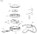
- FIG. 6 is an exploded view of the main body 200 of the body fluid observation device according to an example of the present disclosure
- FIG. 7 is a vertical cross-sectional view of the main body 200 of the body fluid observation device according to an example of the present disclosure
- FIG. 8 is a view for explaining a case shown in FIGS. 6 and 7 in more detail
- FIG. 9 is a view for explaining an asymmetric structure of the chamber 100 and a guide partition R211x and R211y.
- the main body 200 of the body fluid observation device may include the case 210, an operation part 220, a power supply part 230, a light source part 240, and a lens part 250.
- the case 210 may include first, second, and third case parts 211, 213, and 215, and the first case part 211 may be located at a bottom of the main body 200, the second case part 213 may be located in the middle of the main body 200, and the third case part 215 may be located at a top of the main body 200.
- a space in which the chamber 100 can be inserted, a space in which the light source part 240 and the operation part 220 can be located, and the lens part 250 may be provided in the first case part 211, and the second case part 213 may be located above the first case 211 to cover the operation part 220 so that the space in which the chamber 100 is to be inserted and the space in which the light source part 240 and the operation part 220 are located can be hidden and protected and a position of a battery can be fixed.
- the third case part 215 may be located above the second case part 213 to cover the power supply part 230 and may be detachable from the second case part 213 so that the user can easily replace the battery.
- the first case part 211 may include a chamber insertion hole H200a, a guide partition R211x and R211y, and an observation hole H200b, as shown in FIG. 8 .
- the chamber insertion hole H200a is located at a front side of the main body 200 through which the chamber 100 is inserted, so that a portion of the first case part 210 is opened to have a length in the second horizontal direction y, thereby allowing the chamber 100 to be inserted.
- the guide partition R211x and R211y may be located at a bottom surface of the first case part 211, and may extend in the first horizontal direction x from the chamber insertion hole H200a to guide an insertion direction and a position of the chamber 100.
- the guide partition R211x and R211y may include a first guide partition R211x extending in the first horizontal direction x and a second guide partition R211y extending in the second horizontal direction y from an end of the first horizontal direction x.
- a shape of the second guide partition R211y may correspond to a planar shape at an end of the chamber 100 in the first horizontal direction x. That is, in the chamber 100 of FIG. 5 , a portion adjacent to a center line II of the chamber 100 at the end in the first horizontal direction x may have a recessed portion and a planar shape to be inclined diagonally relative to the first and second horizontal directions (x, y) may be provided, and, as shown in FIG. 8 , a shape of the second guide partition R211y may also have a portion recessed inward at the end with respect to the center line in the first horizontal direction x and a planar shape to be inclined diagonally relative to the first and second horizontal directions may be provided.
- the guide partition R211x and R211y may be able to more accurately guide the position of the chamber 100 in the first and second horizontal directions.
- the guide partitions R211x and R211y may be able to guide the chamber 100 so that, when the chamber 100 is inserted into the main body 200 through the chamber insertion hole H200a, the chamber 100 can be accurately positioned at a desired part and the body fluid receiving groove 110 of the chamber 100 can be accurately positioned on the observation hole H200b.
- each of the chamber 100 and the guide partition R211x and R211y may have an asymmetric shape with respect to the center line as shown in FIG. 9 .
- the planar shape of the end of the first horizontal direction x may be formed to be asymmetric in both sides thereof with respect to a center line CL100 parallel to the first horizontal direction x, and, in the guide partition R211x and R211y, a shape of the second guide partition R211y extending in the second horizontal direction y may be asymmetric in both sides thereof with respect to a center line CL211 parallel to the first horizontal direction x.
- the chamber 100 may have a chamfered portion P100 formed diagonally relative to the first and second horizontal directions at an end in the first horizontal direction x, the chamfered portion P1 which is a corner on any one of both sides with respect to the center line CL100.
- the guide partition R211x and R211y may also has a chamfered partition PR211 diagonally formed in each of the first and second guide partitions R211x and R211y at an end in the first horizontal direction so that a corner on any one of both sides with respect to the center line CL211 corresponds to the shape of the chamfered portion P100 of the chamber 100.
- the chamber 100 may be completely inserted into the main body 200, and when the chamber 100 is inserted in a different direction than intended or desired, the chamber 100 may not be completely inserted into the main body 200.
- the chamber 100 when the chamber 100 is inserted upside down, the chamber 100 may be prevented from being completely inserted into the main body 200. Accordingly, it is possible to further enhance user convenience.
- the observation hole H200b may be formed at the bottom surface of the first case part 211 to observe body fluid and thus provided at the bottom surface of the main body 200, and the observation hole H200b may be overlapped with the body fluid receiving groove 100 of the chamber 100 in the vertical direction z.
- the observation hole H200b may be provided with the lens part 250 that is fixedly coupled to the observation hole H200b, as shown in FIG. 8 , to enlarge an image of the body fluid.
- the magnification of the lens part 250 may be, for example, 100 to 500 times, and the lens part 250 may be coupled to a camera provided in the user terminal 10 to enlarge body fluid received in the chamber 100 at magnification of 700 to1300 times.
- the present disclosure is not necessarily limited to the above-described magnification of the lens part 250.
- the light source part 240 may be located above the body fluid receiving groove 110 of the chamber 100 and emit light to the body fluid receiving groove 110. Accordingly, the user may be able to observe the body fluid more clearly.
- the operation part 220 may be located in an upper portion of the chamber 100 in the first case part 211 and may be electrically connected to the light source part 240 to operate the light source part 240.
- the operation part 220 may include a substrate 221 and 223 provided with an electrical circuit pattern for operating the light source part 240, and the light source part 240 may be located at the center of the substrate 221 and 223 while located above the body fluid seating portion of the chamber 100.
- the operation part 220 may form an electric closed loop for operating the light source part 240, and accordingly, the operation part 220 may operate the light source part 240 so that light can be lighted from the light source part 240.
- the user may be able to more clearly observe the body fluid located in the body fluid receiving groove 110 of the chamber 100 through the observation hole H200b with the naked eye or through the user terminal 10.
- a first substrate 221 and a second substrate 223 may be provided in multiple layers.
- the first substrate 221 may be provided with a circuit pattern electrically connected to the light source part 240, and the light source part 240 may be located in the middle of the first substrate 221, the second substrate 223 may be located under the first substrate 221 and may be electrically connected to the first substrate 221, and an operation switch 225 to form an electric closed loop upon insertion of the chamber 100 may be provided. This will be described in more detail with reference to FIGS. 10 and 11 .
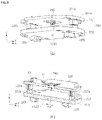
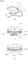
- FIG. 10 is a view for explaining in more detail an example of the operation part 220 according to the present disclosure
- FIG. 11 is a view for explaining a method of operating the operation part 220 shown in FIG. 9
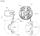
- FIG. 12 is a view for explaining another example of the operation part 220 according to the present disclosure.
- FIG. 10 (a) shows a perspective view of the operation part 220
- FIG. 10 (b) shows a cross-section of the operation part 220, shown in FIG. 10 (a) , which is taken along in the second horizontal direction y.
- an example of the operation part 220 may include an operation switch 225 that forms an electric closed loop for operating the light source part 240 when the chamber 100 is inserted into the chamber insertion hole H200a.
- the operation part 220 may be formed in multiple layers, and may include a first substrate 221 located at an upper side and a second substrate 223 positioned at a lower side.
- the first substrate 221 may have a light source part 240 positioned in a central portion thereof, and a power supply connection terminal E1 and E2 to which a battery of the power supply part is connected may be provided at the first substrate 221.
- a light transmission hole H223 through which the light emitted from the light source part 240 passes may be provided, so that light emitted from the light source part 240 located thereabove can transmit.
- a diameter R1 of the light transmission hole may be, for example, 0.5 to 2.5mm, but this is merely an example, and the diameter R1 of the light transmission hole may vary depending on a distance between the light source part 240 and the light transmission hole H223.
- first substrate 221 and the second substrate 223 may be electrically connected to each other.
- a first connector 227a may be provided under the first board 221
- a second connector 227b may be provided on the second board 223, and the first substrate 221, and as the second connector 227b is inserted into the first connector 227a, the second substrate 223 may be electrically connected to each other.
- the operation switch 225 forming an electric closed loop may be provided under the second substrate 223, and each operation switch 225 may have a switch terminal protruding toward the light transmission hole H223 located in a central portion of the second substrate 223.
- the operation switch 225 may be located on an extension line of the guide partition R211x and R211y.
- the operation switch 225 may be located on an extension line of the first guide partition R211x extending in the first horizontal direction x, for example, as shown in FIG. 11 .
- the switch terminal of the operation switch 225 may protrude inwardly than the extension line of the guide partition R211x and R211y, so that the switch terminal of the operation switch 225 can be pressed by the chamber upon insertion of the chamber 100.
- the present disclosure is not necessarily limited thereto, and the operation switch 225 may be located on an extension line of the second guide partition R211y extending in the second horizontal direction y. That is, it is also possible that the operation switch 225 is located on the side of the second guide partition R211y so as to contact an end of the chamber 100 in the first horizontal direction x.
- the operation switch 225 provided in the second substrate 223 may be turned on by being pressed by the chamber 100 while the chamber 100 is inserted into the chamber insertion hole H200a, so that an electric closed loop for operating the light source part 240 can be formed.
- the operation part 220 of the present disclosure is not necessarily limited to the structure including the operation switch 225 as shown in FIGS. 10 and 11 , and may have other structures.
- the operation part 220 may have a structure in which an electric closed loop is formed together with the chamber 100 when the chamber 100 is inserted into the chamber insertion hole H200a.
- the chamber 100 may include a chamber electrode 100E1 and 100E2 having an electrode pattern of a conductive material at an end in the first horizontal direction x.
- the chamber electrodes 100E1 and 100E2 may include first and second chamber electrodes 100E1 and 100E2 formed in the vertical direction z at the end of the first horizontal direction x in the chamber 100, the first and second chamber electrodes 100E1 and 100E2 may be spaced apart from each other in the second direction, and the first and second chamber electrodes 100E1 and 100E2 may be electrically connected to each other by a chamber electrode line 100CE.
- the operation part 220 may include a guide electrode 210E1 and 210E2 located at a portion of the guide partitions R211x and R211y corresponding to the chamber electrode 100E1 and 100E2, so that the guide electrode 210E1 and 210E2 can be connected to the chamber electrode 100E1 and 100E2 upon insertion of the chamber 100.
- a position corresponding to the chamber electrodes 100E1 and 100E2 may be, for example, an inner side of the second guide partition R211y, and the guide electrode 210E1, 210E2 may be formed in the vertical direction z to the second guide partitions R211y.
- the guide electrode 210E1 and 210E2 may be electrically connected to a circuit pattern of the substrate 221 and 223 included in the operation part 220.
- the guide electrode 210E1 and 210E2 provided in the guide partition R211x and R211y and the chamber electrode 100E1 and 100E2 provided in the chamber 100 may contact each other, thereby forming an electric closed loop for operating the light source part 240. Therefore, in order to observe the body fluid, the user may simply insert the chamber 100 into the main body 200 so as to control light to be emitted from the light source unit 240, thereby enabled to observe body fluid more conveniently.
- the structure of the chamber 100 described with reference to FIG. 5 is a structure in which, when the chamber 100 is inserted into the chamber insertion hole H200a of the main body 200, the chamber 100 can be inserted even with the upper and lower sides inverted. In this case, the body fluid cannot be observed properly.
- body fluid may flow out of the body fluid receiving groove 110 of the chamber 100 and contaminate the surface of the lens part 250, thereby obstructing the user's observation of the body fluid.
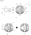
- FIG. 13 is a view for explaining a modified example of a chamber 100' according to an example of the present disclosure.
- FIG. 13 (a) shows an upper surface of the chamber 100' according to the modified example
- FIG. 13 (b) shows a lower surface of the chamber 100' according to the modified example
- FIG. 13 (c) shows a cross-section taken along II-II line in FIG. 13 (a)
- FIG. 13 (d) is a modified example of a case of a main body 200, which is modified to allow the chamber 100' can be inserted.
- the chamber 100' according to another example of the present disclosure may have the same upper surface structure as that of the chamber 100' according to the example of the present disclosure described with reference to FIG. 5
- the chamber 100' may include a guide protrusion 120 protruding downward from a lower surface thereof.
- a protrusion length DT of the guide protrusion 120 may be identical to a thickness T1 of a body portion of the chamber 100' from the lower surface of the chamber 100', for example, as shown in FIG. 13 (c) . That is, a thickness of a portion where the guide protrusion 120 is formed may be about twice a thickness of a body portion of the chamber 100'.
- the present disclosure is not necessarily limited thereto, and the protrusion length DT of the guide protrusion 120 may vary as long as a thickness (T1+TD) of a portion where the guide protrusion 120 is formed is greater than a height of the chamber insertion hole H200a, so that when the chamber 100' is inserted into the chamber insertion hole H200a, the chamber insertion hole H200a can be caught by the guide protrusion 120 to prevent the chamber 100' from being inserted any longer.
- the guide protrusion 120 is illustrated as an example in the form of a triangular prism, but not necessarily limited thereto, and the guide protrusion 120 may take the shape of a cylindrical or polygonal prism.
- the case of the main body 200 may also be modified to have a guide groove 120H into which the guide protrusion 120 of the chamber 100' is inserted.
- the guide groove 120H is located below the chamber insertion hole H200a, and when the chamber 100' is completely inserted into the chamber insertion hole H200a, the guide protrusion 120 of the chamber 100' may be inserted in the first horizontal direction x.
- a shape of the guide groove 120H may be formed to correspond to a shape of the guide protrusion 120.
- the chamber 100' and the main body 200 may physically prevent insertion of the chamber 100'when the user tries to insert the chamber 100' upside down into the main body 200, and thus, it is possible to induce the user to correctly use the body fluid observation device and to prevent the surface of the lens part 250 in the main body 200 from being contaminated.
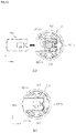
- FIGS. 14 and 15 are views for explaining a structure in which the main body holder 300 and the main body 200 are coupled in the body fluid observation device according to an example of the present disclosure
- FIG. 14 (a) is a view for explaining an example of the main body holder 300 coupled to the body 200
- FIG. 14 (b) and FIG. 14 (c) are views for explaining an outer shape of the case to which the main body holder 300 can be more rigidly and precisely coupled when the main body holder 300 is coupled to the body 200.
- FIG. 14 (b) shows a front side of the case
- FIG. 14 (c) shows a rear side of the case
- FIG. 15 shows a cross-section in which the main body 200 and the main body holder 300 are coupled to each other.
- the case of the main body 200 may include a case coupling groove 200H1 recessed along an outer circumferential surface to allow coupling with the main body holder 300, so that a coupling wing portion 310 of the main body holder 300 is coupled.
- the case coupling groove 200H1 may be recessed into the case of the main body 200 and may extend along the outer circumferential surface with a predetermined width.
- a first locking protrusion 200P1 protruding from a bottom surface of the case coupling groove 200H1 may be provided in both portions adjacent to the chamber insertion hole H200a in the case coupling groove 200H1, and as shown in FIG. 14 (c) , second locking protrusions 200P2 may be provided at a rear side located opposite to the chamber insertion hole H200a in the case coupling groove 200H1.
- a recessed groove 200H2 may be provided between the second locking protrusions 200P2.
- the body holder 300 may include the coupling wing portion 310 and a body portion 320, as shown in FIG. 14 (a) .
- the coupling wing portion 310 may be formed in an arc shape to surround the outer circumferential surface of the case and may be inserted into the case coupling groove 200H1, and the body portion 320 may extend from a central portion of the coupling wing portion 310 to be coupled to a user terminal. Such a coupled state is shown in FIG. 3 .
- the coupling wing portion 310 may be formed in a circular arc shape and have elasticity, and the circular arc shape may have a longer length than that of a semicircle, so that the main body 200 can be fitted into the arc of the coupling wing portion.
- the coupling wing portion 310 may include a first locking groove 310a and a second locking groove 310b, the first locking groove 310a may be located at both ends of the arc of the main body 200 so that the first locking protrusion 200P1 can be inserted, and the second locking groove 310b may be located at a central portion of the arc so that the second locking protrusion 200P2 of the main body 200 can be inserted.
- a separate protrusion 310c may be provided inside the second locking groove 310b.
- the first locking protrusion 200P1 of the main body 200 may be inserted into the first locking groove 310a of the coupling wing portion 310 and the second locking protrusion 200P2 of the main body 200 may be inserted into the second locking groove 310b of the coupling wing portion 310, so that the main body 200 can be in closer contact with and more firmly fixed to the coupling wing portion 310 of the main body holder 300.
- FIG. 16 is a view for explaining a modified example of the coupling holder shown in FIG.
- the body holder 300 may have a deformation preventing hole 300H in a portion connected to the body 320 in the coupling wing 310.
- the deformation prevention hole 300H may be formed to have a length in a direction parallel to the arc of the coupling wing and may pass through the coupling wing portion 310.
- the deformation prevention hole 300H may prevent deformation of the main body holder 300 caused by a difference in thermal expansion coefficient when the main body holder 300 is manufactured, and the deformation prevention hole 300H may also solve the problem that the main body 200 is not firmly fixed and is easily separated from the coupling wing portion 310 when the main body 200 is fitted even if the main body holder is manufactured without deformation.
- the main body holder 300 may be manufactured by an injection molding method, and a difference in thermal expansion coefficient occurs due to a difference in thickness and width between the coupling wing portion 310 and the body portion 320, which may cause the main body holder 300 to be easily deformed during the manufacturing process.
- the deformation prevention hole 300H may reduce the difference in thermal expansion coefficient between the coupling wing portion 310 and the body portion 320, thereby preventing deformation of the main body holder 300.
- the entrance of the coupling wing portion 310 may be formed to be opened and closed when the main body 200 is inserted into the coupling wing portion 310 and, in this case, in a case where the deformation preventing hole 300H is provided as in the present disclosure, the deformation prevention hole 300H physically alleviates pressure to the coupling wing portion 310 upon insertion of the main body 200, so that the main body 310 can be more easily fitted and coupled to the coupling wing portion 310 without damage to the coupling wing portion 310.
Landscapes
- Health & Medical Sciences (AREA)
- Life Sciences & Earth Sciences (AREA)
- Engineering & Computer Science (AREA)
- Biomedical Technology (AREA)
- Physics & Mathematics (AREA)
- General Health & Medical Sciences (AREA)
- Pathology (AREA)
- Molecular Biology (AREA)
- Veterinary Medicine (AREA)
- Public Health (AREA)
- Animal Behavior & Ethology (AREA)
- Surgery (AREA)
- Medical Informatics (AREA)
- Heart & Thoracic Surgery (AREA)
- Biophysics (AREA)
- Chemical & Material Sciences (AREA)
- Hematology (AREA)
- Optics & Photonics (AREA)
- Urology & Nephrology (AREA)
- General Physics & Mathematics (AREA)
- Biochemistry (AREA)
- Analytical Chemistry (AREA)
- Medicinal Chemistry (AREA)
- Food Science & Technology (AREA)
- Immunology (AREA)
- Spectroscopy & Molecular Physics (AREA)
- Reproductive Health (AREA)
- Pulmonology (AREA)
- Endoscopes (AREA)
- Sampling And Sample Adjustment (AREA)
- Accessories Of Cameras (AREA)
Applications Claiming Priority (3)
| Application Number | Priority Date | Filing Date | Title |
|---|---|---|---|
| KR20190158435 | 2019-12-02 | ||
| KR1020200115123A KR102470260B1 (ko) | 2019-12-02 | 2020-09-09 | 체액 관찰 기기 |
| PCT/KR2020/013992 WO2021112393A1 (ko) | 2019-12-02 | 2020-10-14 | 체액 관찰 기기 |
Publications (2)
| Publication Number | Publication Date |
|---|---|
| EP4062829A1 true EP4062829A1 (de) | 2022-09-28 |
| EP4062829A4 EP4062829A4 (de) | 2023-01-18 |
Family
ID=76222109
Family Applications (1)
| Application Number | Title | Priority Date | Filing Date |
|---|---|---|---|
| EP20896079.9A Pending EP4062829A4 (de) | 2019-12-02 | 2020-10-14 | Vorrichtung zur beobachtung von körperflüssigkeiten |
Country Status (5)
| Country | Link |
|---|---|
| US (1) | US20220409103A1 (de) |
| EP (1) | EP4062829A4 (de) |
| JP (1) | JP2023504180A (de) |
| CN (1) | CN114786575A (de) |
| WO (1) | WO2021112393A1 (de) |
Families Citing this family (3)
| Publication number | Priority date | Publication date | Assignee | Title |
|---|---|---|---|---|
| USD1071187S1 (en) * | 2021-09-03 | 2025-04-15 | Withings | Urine analysis station |
| USD1112807S1 (en) * | 2025-01-07 | 2026-02-10 | Withings | Urine analysis device |
| USD1114291S1 (en) * | 2025-01-07 | 2026-02-17 | Withings | Urine analysis device |
Family Cites Families (14)
| Publication number | Priority date | Publication date | Assignee | Title |
|---|---|---|---|---|
| US5728352A (en) * | 1994-11-14 | 1998-03-17 | Advanced Care Products | Disposable electronic diagnostic instrument |
| US6175752B1 (en) * | 1998-04-30 | 2001-01-16 | Therasense, Inc. | Analyte monitoring device and methods of use |
| KR200276068Y1 (ko) * | 2002-01-02 | 2002-05-18 | 한보림 | 광원일체형 접속구 |
| JP6294012B2 (ja) * | 2012-07-02 | 2018-03-14 | グリッドマーク株式会社 | レンズユニット |
| TWI533025B (zh) * | 2014-07-07 | 2016-05-11 | 億觀生物科技股份有限公司 | 可攜式顯微鏡裝置 |
| US10118176B2 (en) * | 2014-10-17 | 2018-11-06 | Omni International, Inc. | Sample-tube holder for easy tube insertion and removal |
| TWM518066U (zh) * | 2015-10-29 | 2016-03-01 | Women S Guard Biomedical Technology Corp | 排卵測定器結構 |
| KR101813867B1 (ko) * | 2015-12-15 | 2018-01-02 | (주)종로의료기 | 조명광을 이용한 체액 분석용 검사장치 |
| WO2017151642A1 (en) * | 2016-02-29 | 2017-09-08 | Flora Bioscience, Inc. | Detection apparatus |
| KR20170133833A (ko) * | 2016-05-26 | 2017-12-06 | (주)종로의료기 | 독립형 휴대용 체액 검사장치 |
| US20190261960A1 (en) * | 2016-10-28 | 2019-08-29 | Manigene Co., Ltd. | Image processing and analyzing system for ovulation detection and method for controlling same |
| KR101920272B1 (ko) * | 2016-11-22 | 2018-11-20 | (주)인트인 | 조명이 개선된 체액 검사장치 |
| TWI882519B (zh) * | 2017-01-10 | 2025-05-01 | 美商集聯健康有限公司 | 用於收集和儲存來自受試者之血液的裝置 |
| CN108333163B (zh) * | 2018-04-08 | 2024-05-03 | 中国人民解放军南京军区南京总医院 | 一种便携式血液安全筛查荧光免疫分析系统 |
-
2020
- 2020-10-14 US US17/781,017 patent/US20220409103A1/en active Pending
- 2020-10-14 CN CN202080083664.2A patent/CN114786575A/zh active Pending
- 2020-10-14 JP JP2022532815A patent/JP2023504180A/ja active Pending
- 2020-10-14 WO PCT/KR2020/013992 patent/WO2021112393A1/ko not_active Ceased
- 2020-10-14 EP EP20896079.9A patent/EP4062829A4/de active Pending
Also Published As
| Publication number | Publication date |
|---|---|
| EP4062829A4 (de) | 2023-01-18 |
| US20220409103A1 (en) | 2022-12-29 |
| CN114786575A (zh) | 2022-07-22 |
| WO2021112393A1 (ko) | 2021-06-10 |
| JP2023504180A (ja) | 2023-02-01 |
Similar Documents
| Publication | Publication Date | Title |
|---|---|---|
| EP4062829A1 (de) | Vorrichtung zur beobachtung von körperflüssigkeiten | |
| US7896704B2 (en) | Strip connectors for measurement devices | |
| US9417205B2 (en) | Analyte measurement devices and systems, and components and methods related thereto | |
| KR102435175B1 (ko) | 체액 관찰 기기 | |
| JP6883114B2 (ja) | 照明が改善された体液検査装置 | |
| US20200281534A1 (en) | Health monitoring device that includes a compact oximeter | |
| KR102470260B1 (ko) | 체액 관찰 기기 | |
| EP3517957A1 (de) | Prüfanordnung und prüfeinrichtung für lateral flow assay | |
| JP2018528402A (ja) | 液体サンプルの分析装置 | |
| CN103531957B (zh) | 滑块式插座连接器 | |
| JP2010071644A (ja) | 分析用デバイス | |
| WO2020098583A1 (zh) | 用于植入式分析物传感器的固定件和传感器系统 | |
| KR102333043B1 (ko) | 체액 테스트기 | |
| JP4844251B2 (ja) | 血液検査装置 | |
| CN208625651U (zh) | 一种手持式动物内窥镜 | |
| TWI623159B (zh) | Card holding member and card connector | |
| CN217886694U (zh) | 具有血糖检测功能的药物注射笔 | |
| US20250314596A1 (en) | Liquid substance inspecting apparatus | |
| KR20240033664A (ko) | 부착 위치를 감지할 수 있는 웨어러블 장치 | |
| US9876302B2 (en) | Medical instrument and drive unit each having an interface for electrically connecting the drive unit with the medical instrument | |
| WO1998019197A1 (en) | A pocket microscope device, with a limited run of the eye-piece and the aimed observation of the sole prepared frame, for the determination of the woman's fertility | |
| KR101574769B1 (ko) | 휴대용 생체정보측정기 | |
| US20080030210A1 (en) | Test socket | |
| TWM545904U (zh) | 搭配行動裝置進行生理特性檢測的配件 |
Legal Events
| Date | Code | Title | Description |
|---|---|---|---|
| STAA | Information on the status of an ep patent application or granted ep patent |
Free format text: STATUS: THE INTERNATIONAL PUBLICATION HAS BEEN MADE |
|
| PUAI | Public reference made under article 153(3) epc to a published international application that has entered the european phase |
Free format text: ORIGINAL CODE: 0009012 |
|
| STAA | Information on the status of an ep patent application or granted ep patent |
Free format text: STATUS: REQUEST FOR EXAMINATION WAS MADE |
|
| 17P | Request for examination filed |
Effective date: 20220624 |
|
| AK | Designated contracting states |
Kind code of ref document: A1 Designated state(s): AL AT BE BG CH CY CZ DE DK EE ES FI FR GB GR HR HU IE IS IT LI LT LU LV MC MK MT NL NO PL PT RO RS SE SI SK SM TR |
|
| A4 | Supplementary search report drawn up and despatched |
Effective date: 20221220 |
|
| RIC1 | Information provided on ipc code assigned before grant |
Ipc: G01N 33/487 20060101ALI20221214BHEP Ipc: A61B 10/00 20060101ALI20221214BHEP Ipc: A61B 5/00 20060101ALI20221214BHEP Ipc: A61B 5/145 20060101AFI20221214BHEP |
|
| DAV | Request for validation of the european patent (deleted) | ||
| DAX | Request for extension of the european patent (deleted) | ||
| STAA | Information on the status of an ep patent application or granted ep patent |
Free format text: STATUS: EXAMINATION IS IN PROGRESS |
|
| 17Q | First examination report despatched |
Effective date: 20240227 |