EP4061659B1 - Vorrichtung zum schutz der traktionsbatterie von elektrofahrzeugen - Google Patents
Vorrichtung zum schutz der traktionsbatterie von elektrofahrzeugen Download PDFInfo
- Publication number
- EP4061659B1 EP4061659B1 EP20803216.9A EP20803216A EP4061659B1 EP 4061659 B1 EP4061659 B1 EP 4061659B1 EP 20803216 A EP20803216 A EP 20803216A EP 4061659 B1 EP4061659 B1 EP 4061659B1
- Authority
- EP
- European Patent Office
- Prior art keywords
- protective device
- tray
- rear axle
- crosspiece
- battery
- Prior art date
- Legal status (The legal status is an assumption and is not a legal conclusion. Google has not performed a legal analysis and makes no representation as to the accuracy of the status listed.)
- Active
Links
Images


Classifications
-
- B—PERFORMING OPERATIONS; TRANSPORTING
- B60—VEHICLES IN GENERAL
- B60K—ARRANGEMENT OR MOUNTING OF PROPULSION UNITS OR OF TRANSMISSIONS IN VEHICLES; ARRANGEMENT OR MOUNTING OF PLURAL DIVERSE PRIME-MOVERS IN VEHICLES; AUXILIARY DRIVES FOR VEHICLES; INSTRUMENTATION OR DASHBOARDS FOR VEHICLES; ARRANGEMENTS IN CONNECTION WITH COOLING, AIR INTAKE, GAS EXHAUST OR FUEL SUPPLY OF PROPULSION UNITS IN VEHICLES
- B60K1/00—Arrangement or mounting of electrical propulsion units
- B60K1/04—Arrangement or mounting of electrical propulsion units of the electric storage means for propulsion
-
- B—PERFORMING OPERATIONS; TRANSPORTING
- B62—LAND VEHICLES FOR TRAVELLING OTHERWISE THAN ON RAILS
- B62D—MOTOR VEHICLES; TRAILERS
- B62D21/00—Understructures, i.e. chassis frame on which a vehicle body may be mounted
- B62D21/15—Understructures, i.e. chassis frame on which a vehicle body may be mounted having impact absorbing means, e.g. a frame designed to permanently or temporarily change shape or dimension upon impact with another body
- B62D21/152—Front or rear frames
-
- B—PERFORMING OPERATIONS; TRANSPORTING
- B60—VEHICLES IN GENERAL
- B60K—ARRANGEMENT OR MOUNTING OF PROPULSION UNITS OR OF TRANSMISSIONS IN VEHICLES; ARRANGEMENT OR MOUNTING OF PLURAL DIVERSE PRIME-MOVERS IN VEHICLES; AUXILIARY DRIVES FOR VEHICLES; INSTRUMENTATION OR DASHBOARDS FOR VEHICLES; ARRANGEMENTS IN CONNECTION WITH COOLING, AIR INTAKE, GAS EXHAUST OR FUEL SUPPLY OF PROPULSION UNITS IN VEHICLES
- B60K1/00—Arrangement or mounting of electrical propulsion units
- B60K1/04—Arrangement or mounting of electrical propulsion units of the electric storage means for propulsion
- B60K2001/0405—Arrangement or mounting of electrical propulsion units of the electric storage means for propulsion characterised by their position
- B60K2001/0416—Arrangement in the rear part of the vehicle
-
- B—PERFORMING OPERATIONS; TRANSPORTING
- B60—VEHICLES IN GENERAL
- B60K—ARRANGEMENT OR MOUNTING OF PROPULSION UNITS OR OF TRANSMISSIONS IN VEHICLES; ARRANGEMENT OR MOUNTING OF PLURAL DIVERSE PRIME-MOVERS IN VEHICLES; AUXILIARY DRIVES FOR VEHICLES; INSTRUMENTATION OR DASHBOARDS FOR VEHICLES; ARRANGEMENTS IN CONNECTION WITH COOLING, AIR INTAKE, GAS EXHAUST OR FUEL SUPPLY OF PROPULSION UNITS IN VEHICLES
- B60K1/00—Arrangement or mounting of electrical propulsion units
- B60K1/04—Arrangement or mounting of electrical propulsion units of the electric storage means for propulsion
- B60K2001/0405—Arrangement or mounting of electrical propulsion units of the electric storage means for propulsion characterised by their position
- B60K2001/0438—Arrangement under the floor
-
- B—PERFORMING OPERATIONS; TRANSPORTING
- B60—VEHICLES IN GENERAL
- B60Y—INDEXING SCHEME RELATING TO ASPECTS CROSS-CUTTING VEHICLE TECHNOLOGY
- B60Y2306/00—Other features of vehicle sub-units
- B60Y2306/01—Reducing damages in case of crash, e.g. by improving battery protection
Definitions
- the invention applies to the field of protection of the traction battery fitted to motor vehicles with electric motors.
- Electric vehicles are equipped with batteries intended to provide them with sufficient autonomy. However, these batteries are notably heavier, more bulky and have a higher voltage than ordinary batteries on board equivalent models of thermally powered vehicles.
- the traction battery modules of electric vehicles are packaged and enclosed in trays located under the floor and mounted between the front of the vehicle and the rear seat floor where they occupy all the available space which is freed by the absence of a fuel tank.
- an impact at the rear of the vehicle can cause uncontrolled recoil of the rear axle (by breakage of the fixing members on the body or by direct contact of the axle cross member on the cover of the battery tray under load) and cause damage to the battery modules and, consequently, a risk of fire.
- the traction batteries of electric vehicles require reinforced and adapted means of protection because this type of vehicle must meet more severe constraints, particularly in the USA, to ensure the safety of people in the event of an accident, and in particular, to preserve the integrity of the battery modules in the event of an impact and thus avoid short circuits.
- the trays supporting the battery modules are provided with an at least partially peripheral frame, comprising two side rails connected, via an elbow connection, to a rear crosspiece.
- the patent FR2972169B1 describes a vehicle chassis, in particular with electric propulsion, comprising a platform carrying two substantially parallel intermediate spars arranged at a distance from one another in a central position between lateral spars connected transversely by a bottom plate forming an intermediate compartment which can accommodate an energy reservoir, such as a battery.
- the patent FR3000459B1 describes a chassis for electric vehicles comprising, on the one hand, tubular shoes ensuring the angular connection and assembly between longitudinal elements and transverse elements of the chassis structure and, on the other hand, frames intended to receive rolling trains.
- the document WO 2012/028956 A1 also shows a device for protecting the battery of an electric vehicle against impacts on the rear axle.
- chassis elements proposed in these patents are neither designed nor adapted to reinforce the structuring frame of the battery tray so as to allow, without an intermediate part, to increase its potential for energy absorption and thus preserving the traction battery in the event of impacts on the rear axle of the vehicle.
- the invention aims to resolve the technical problems mentioned above by proposing a protective device ensuring, at the same time, selective deformation kinematics of the rear axle of the vehicle and effective absorption of shocks by the frame of the battery tray.
- a device for protecting the battery of an electric vehicle against impacts from the rear axle said battery being packaged in a container provided with a frame comprising, on both sides other of the tray, a spar whose end is connected, via a bent connection zone, to the lateral end facing a rear cross member and whose outer side is provided with at least one tray support element on the body of the vehicle, characterized in that each connection zone comprises a nozzle projecting towards the rear formed by the joining of at least two protrusions carried by the respective ends of the spar and crossmember.
- the protrusions of the spars extend below the protrusions of the crosspiece.
- the nozzles further comprise protrusions carried by the support elements of the tray.
- the protrusions of the support elements of the tray extend above the protrusions of the crosspiece.
- the slats have a divergent inclination of between 120° and 150° relative to the vertical plane passing through the axis of the crosspiece.
- the rear axle carries two symmetrical stops extending forwards towards the noses of the frame.
- the tray support elements each carry two substantially horizontal mounting plates on the body of the vehicle.
- these plates define between them a slot intended to receive, in the event of an impact, a yoke carried by a deformable longitudinal arm for fixing the rear axle.
- the stops are mounted between the deformable longitudinal arms for fixing the rear axle.
- Another object of the invention is an electric vehicle equipped with a battery packaged in a container provided with a protection device against impacts having the characteristics defined above.
- the device of the invention makes it possible to preserve the battery modules of the traction battery against possible deformations resulting from a high-speed rear-end collision with another vehicle.
- the device of the invention integrates perfectly with the design of the battery tray frame and offers a maximum level of safety even for the most severe rear impacts.
- the device of the invention complies with American standards which require the impact zone to be covered by at least 70% of the rear axle for an impact with a vehicle weighing approximately 1.4 tonnes and traveling at 80 km/h. h.
- the programmed deformation kinematics (by buckling) of the rear axle longitudinal arm makes it possible to very precisely locate its impact zone on the crosspiece of the battery tray frame which has been reinforced for this purpose by the presence of a beak.
- a test was carried out with a 1368 kg impactor cart launched at more than 80 km/h generating an incident kinetic energy of approximately 346 kilojoules.
- the stop contact thus occurs in an offset manner, for example, via the support of the bottoming stop, and contributes to keeping the crosspiece away from the battery.
- the frame of the battery tray is capable of absorbing the kinetic energy of the impact without deforming the tray by keeping the rear axle crossmember at a distance while limiting the deceleration transmitted to the modules via the frame.
- the rear axle intended for electric vehicles, is adapted and combined with the reinforced frame of the battery tray and its specific mode of deformation (in particular, at the level of its longitudinal arms) makes it possible to increase the energy absorption potential thus securing the battery modules.
- the protection device of the invention can be transposed to the different wheelbases of modular platforms dedicated to vehicle production lines and, in particular, those intended for electric vehicles (known as eCMP for “ electric Common Modular Platform ”) .
- the device of the invention is intended for the protection of the traction battery modules of electric vehicles which are packaged and enclosed in bins (not shown) located in a space 10 located under the floor between the front of the vehicle and the rear seat floor.
- Such a tank is provided with a frame 1, at least partially peripheral, comprising, on either side of the tank, a spar 11a, 11b.
- the ends of these spars are connected, via bent connection zones, to the lateral ends facing a rear cross member 12.
- the outer side of the spars 11a, 11b is provided with at least one, and here with two support elements of the bin on the body of the vehicle, as shown in the figure 1 .
- the two lateral support elements of the tray are formed of two substantially horizontal plates 13 in which orifices are provided for fitting members (not shown) for fixing to the body of the vehicle.
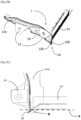
- the frame 1 is positioned immediately behind the tray, preferably at the level of its cover, and in front of the rear axle 2 of the vehicle which carries, for its part, longitudinal arms 21 for fixing to the body, as illustrated in the Figure 3 .
- the invention aims to reinforce the frame 1 of the tank while presenting a selective impact zone for the rear axle 2 in the event of a rear-end collision.
- each of the bent lateral connection zones has a nozzle 14 projecting towards the rear, formed of the joining of at least two protrusions 110, 120 carried by the respective ends of the longitudinal beams 11a, 11b and the crosspiece 12.
- the rebate of the two side noses 14 has a divergent inclination a between 120° and 150° relative to the vertical plane passing through the axis X of the crosspiece 12, as illustrated by the Figure 2C .
- each nozzle 14 further comprises a projection 130 also carried by the support element 13 of the tray associated with it.
- the protrusions 110 of the longitudinal members 11a, 11b extend below the protrusions 120 of the crosspiece 12 while the protrusions 130 of the tray support elements 13 extend above the protrusions 120 of the crosspiece 12, as illustrated by the figures 2A And 2B .
- the invention also provides that the rear axle 2 carries two symmetrical stops 22a, 22b extending forwards towards the noses 14 of the frame 1 of the tank. These stops are mounted between deformable longitudinal arms 21 for fixing the rear axle 2 to the body of the vehicle, as illustrated by the Figure 3 .
- the plates 13 of the tray support elements delimit between them a slot 15 (visible on the figures 1 , 2B And 4B ), intended to receive, in the event of an impact, a yoke 23 carried by each of the deformable longitudinal arms 21 of the rear axle 2, as illustrated by the figures 4A And 4B .
Landscapes
- Engineering & Computer Science (AREA)
- Chemical & Material Sciences (AREA)
- Combustion & Propulsion (AREA)
- Transportation (AREA)
- Mechanical Engineering (AREA)
- Body Structure For Vehicles (AREA)
- Arrangement Or Mounting Of Propulsion Units For Vehicles (AREA)
- Battery Mounting, Suspending (AREA)
- Cooling, Air Intake And Gas Exhaust, And Fuel Tank Arrangements In Propulsion Units (AREA)
Claims (10)
- Vorrichtung zum Schutz der Batterie eines Elektrofahrzeugs vor Stößen auf die Hinterachse (2), wobei die Batterie in einem Behälter verpackt ist, der mit einem Rahmen (1) versehen ist, der auf beiden Seiten der Wanne je einen Holm (11a, 11b) aufweist sein Ende über eine abgewinkelte Verbindungszone mit dem seitlichen Ende gegenüber einer hinteren Querstrebe (12) verbunden ist und dessen Außenseite mit mindestens einem Stützelement der Wanne versehen ist, dadurch gekennzeichnet, dass jede Verbindungszone einen vorstehenden Schnabel (14) aufweist nach hinten, gebildet durch die Verbindung von mindestens zwei Vorsprüngen (110, 120), die von den jeweiligen Enden des Holms (11a, 11b) und des Querstücks (12) getragen werden.
- Schutzvorrichtung nach Anspruch 1, dadurch gekennzeichnet, dass die Vorsprünge (110) der Seitenteile (11a, 11b) bis unter die Vorsprünge (120) des Querträgers (12) reichen.
- Schutzvorrichtung nach einem der vorhergehenden Ansprüche, dadurch gekennzeichnet, dass die Ausgüsse (14) außerdem Vorsprünge (130) umfassen, die von den Stützelementen der Schale getragen werden.
- Schutzvorrichtung nach dem vorhergehenden Anspruch, dadurch gekennzeichnet, dass die Vorsprünge (130) der Stützelemente der Wanne über die Vorsprünge (120) des Querträgers (12) hinausragen.
- Schutzvorrichtung nach einem der vorhergehenden Ansprüche, dadurch gekennzeichnet, dass die Backen (14) eine divergierende Neigung zwischen 120° und 150° in Bezug auf die vertikale Ebene aufweisen, die durch die Achse des Querträgers (12) verläuft.
- Schutzvorrichtung nach einem der vorhergehenden Ansprüche, dadurch gekennzeichnet, dass die Hinterachse (2) zwei symmetrische Anschläge (22a, 22b) trägt, die sich nach vorne in Richtung der Laschen (14) des Ankers (1) erstrecken.
- Schutzvorrichtung nach einem der vorhergehenden Ansprüche, dadurch gekennzeichnet, dass die Wannentragelemente jeweils zwei im Wesentlichen horizontale Montageplatten (13) an der Karosserie des Fahrzeugs tragen.
- Schutzvorrichtung nach dem vorhergehenden Anspruch, dadurch gekennzeichnet, dass die Platten (13) zwischen sich einen Schlitz (15) begrenzen, der dazu bestimmt ist, im Falle eines Aufpralls ein Joch (23) aufzunehmen, das von einem verformbaren Längsarm (21) getragen wird Hinterachslagerung (2).
- Schutzvorrichtung nach Anspruch 6 und 8, dadurch gekennzeichnet, dass die genannten Anschläge (22a, 22b) zwischen den verformbaren Längsarmen (21) zur Fixierung der Hinterachse (2) angebracht sind.
- Elektrofahrzeug, ausgestattet mit einer Batterie, verpackt in einem Behälter, der mit einer Vorrichtung zum Schutz vor Stößen nach einem der vorhergehenden Ansprüche ausgestattet ist.
Applications Claiming Priority (2)
| Application Number | Priority Date | Filing Date | Title |
|---|---|---|---|
| FR1913070A FR3103450B1 (fr) | 2019-11-22 | 2019-11-22 | Dispositif de protection de la batterie de traction des vehicules electriques |
| PCT/FR2020/051851 WO2021099704A1 (fr) | 2019-11-22 | 2020-10-16 | Dispositif de protection de la batterie de traction des véhicules électriques |
Publications (3)
| Publication Number | Publication Date |
|---|---|
| EP4061659A1 EP4061659A1 (de) | 2022-09-28 |
| EP4061659B1 true EP4061659B1 (de) | 2023-11-29 |
| EP4061659B8 EP4061659B8 (de) | 2024-01-03 |
Family
ID=69811067
Family Applications (1)
| Application Number | Title | Priority Date | Filing Date |
|---|---|---|---|
| EP20803216.9A Active EP4061659B8 (de) | 2019-11-22 | 2020-10-16 | Vorrichtung zum schutz der traktionsbatterie von elektrofahrzeugen |
Country Status (4)
| Country | Link |
|---|---|
| EP (1) | EP4061659B8 (de) |
| CN (1) | CN114728571A (de) |
| FR (1) | FR3103450B1 (de) |
| WO (1) | WO2021099704A1 (de) |
Families Citing this family (1)
| Publication number | Priority date | Publication date | Assignee | Title |
|---|---|---|---|---|
| FR3127463B1 (fr) | 2021-09-29 | 2024-08-09 | Psa Automobiles Sa | Véhicule automobile avec reprise d’effort de choc arrière par un bac de batteries de traction |
Family Cites Families (12)
| Publication number | Priority date | Publication date | Assignee | Title |
|---|---|---|---|---|
| JP5549334B2 (ja) * | 2010-04-07 | 2014-07-16 | 日産自動車株式会社 | 電動車両の車体後部構造 |
| JP5071538B2 (ja) * | 2010-09-03 | 2012-11-14 | トヨタ自動車株式会社 | 車両用電池搭載構造 |
| FR2966092B1 (fr) * | 2010-10-13 | 2013-06-14 | Renault Sa | Structure destinee a recevoir une batterie electrique d'alimentation d'un moteur electrique d'entrainement d'un vehicule automobile |
| FR2972169B1 (fr) | 2011-03-01 | 2013-11-08 | Courb | Chassis modulaire a longerons cintres pour vehicule electrique |
| CN202029895U (zh) * | 2011-03-02 | 2011-11-09 | 重庆小康汽车集团有限公司 | 前驱式微型电动汽车底盘 |
| JP5790365B2 (ja) * | 2011-09-20 | 2015-10-07 | トヨタ自動車株式会社 | 車両用バッテリ搭載構造 |
| JP2013199196A (ja) * | 2012-03-26 | 2013-10-03 | Suzuki Motor Corp | 電気自動車のバッテリパック搭載構造 |
| JP5942672B2 (ja) * | 2012-07-26 | 2016-06-29 | スズキ株式会社 | 車両用バッテリパックの支持構造 |
| FR3000459B1 (fr) | 2012-12-28 | 2016-05-13 | Courb | Chassis pour vehicule terrestre et procede de fabrication correspondant |
| DE102013005571A1 (de) * | 2013-03-30 | 2014-10-02 | Daimler Ag | Tragrahmen zum Halten wenigstens eines Energiespeichers und/oder einer Antriebskomponente eines Kraftwagens |
| DE102015013533B3 (de) * | 2015-10-19 | 2016-09-15 | Audi Ag | Hilfsrahmen für eine Fahrzeug- Hinterachse |
| FR3052720B1 (fr) * | 2016-06-16 | 2019-05-03 | Peugeot Citroen Automobiles Sa | Vehicule dont le train arriere comprend au moins un dispositif d’entretoisement |
-
2019
- 2019-11-22 FR FR1913070A patent/FR3103450B1/fr not_active Expired - Fee Related
-
2020
- 2020-10-16 EP EP20803216.9A patent/EP4061659B8/de active Active
- 2020-10-16 CN CN202080080826.7A patent/CN114728571A/zh active Pending
- 2020-10-16 WO PCT/FR2020/051851 patent/WO2021099704A1/fr not_active Ceased
Also Published As
| Publication number | Publication date |
|---|---|
| WO2021099704A1 (fr) | 2021-05-27 |
| EP4061659B8 (de) | 2024-01-03 |
| CN114728571A (zh) | 2022-07-08 |
| FR3103450A1 (fr) | 2021-05-28 |
| EP4061659A1 (de) | 2022-09-28 |
| FR3103450B1 (fr) | 2021-11-19 |
Similar Documents
| Publication | Publication Date | Title |
|---|---|---|
| EP2834104B1 (de) | Kraftfahrzeugchassis mit mittel zur absorption eines frontaufpralls | |
| EP0854818B1 (de) | Ultraleichtes strassenfahrzeug | |
| EP1874613B1 (de) | Fondboden eines automobils | |
| EP2598394B1 (de) | Fahrzeugchassis mit erhöhtem sitzquerträger | |
| EP4077105B1 (de) | Aufbau eines kraftfahrzeug-hinterteils, das mit seitenelementen und längselementen ausgerüstet ist | |
| EP2782814B1 (de) | Kompaktes stadtfahrzeug | |
| EP2326522A1 (de) | Lagermodul und fahrzeug damit | |
| EP4061659B1 (de) | Vorrichtung zum schutz der traktionsbatterie von elektrofahrzeugen | |
| EP0574281B1 (de) | Kraftfahrzeug mit elektrischem Antrieb, dessen Karrosserie mit sehr wenigen Änderungen von der Karrosserie eines Fahrzeuges mit Brennkraftmaschine abgeleitet ist | |
| EP1693283B1 (de) | Vorderbau für ein Kraftfahrzeug | |
| FR3038574A1 (fr) | Structure de vehicule comportant un element de renfort et vehicule comportant une telle structure | |
| WO2014064368A1 (fr) | Agencement pour la fixation d'un bac de roue de secours de vehicule automobile | |
| EP3362334B1 (de) | Kraftfahrzeug-strukturbauteil und vorderen unterbereich mit einem solchen bauteil | |
| FR3167119A1 (fr) | Structure avec appui façade avant de véhicule automobile | |
| EP3974294B1 (de) | Verfahren zum zusammenbau eines elektro- oder hybridfahrzeugs | |
| FR3166347A1 (fr) | Absorbeur de choc frontal pour structure de véhicule électrique triporteur | |
| EP2822840B1 (de) | Kraftfahrzeugkarosserie mit einem kabelverstärkten verkleidungsbereich | |
| FR3101298A1 (fr) | Support | |
| FR2878209A1 (fr) | Dispositif d'arret de charges en plusieurs parties pour vehicule automobile | |
| FR3166868A1 (fr) | Arrangement de châssis pour un véhicule triporteur | |
| EP4200194A1 (de) | Fahrzeug mit einer vorrichtung zum halten des ersatzrades | |
| WO2022037902A1 (fr) | Véhicule comprenant un dispositif de retenue de la roue de secours | |
| FR3152007A1 (fr) | Plancher de vehicule equipe d’un dispositif anti deversement des traverses d’assise | |
| FR3139106A1 (fr) | Structure de véhicule automobile avec berceau éjectable | |
| EP3386779B1 (de) | Hinterachsanordnung und vorrichtung zur sicherung davon |
Legal Events
| Date | Code | Title | Description |
|---|---|---|---|
| STAA | Information on the status of an ep patent application or granted ep patent |
Free format text: STATUS: UNKNOWN |
|
| STAA | Information on the status of an ep patent application or granted ep patent |
Free format text: STATUS: THE INTERNATIONAL PUBLICATION HAS BEEN MADE |
|
| PUAI | Public reference made under article 153(3) epc to a published international application that has entered the european phase |
Free format text: ORIGINAL CODE: 0009012 |
|
| STAA | Information on the status of an ep patent application or granted ep patent |
Free format text: STATUS: REQUEST FOR EXAMINATION WAS MADE |
|
| 17P | Request for examination filed |
Effective date: 20220406 |
|
| AK | Designated contracting states |
Kind code of ref document: A1 Designated state(s): AL AT BE BG CH CY CZ DE DK EE ES FI FR GB GR HR HU IE IS IT LI LT LU LV MC MK MT NL NO PL PT RO RS SE SI SK SM TR |
|
| DAV | Request for validation of the european patent (deleted) | ||
| DAX | Request for extension of the european patent (deleted) | ||
| GRAP | Despatch of communication of intention to grant a patent |
Free format text: ORIGINAL CODE: EPIDOSNIGR1 |
|
| STAA | Information on the status of an ep patent application or granted ep patent |
Free format text: STATUS: GRANT OF PATENT IS INTENDED |
|
| INTG | Intention to grant announced |
Effective date: 20230720 |
|
| GRAS | Grant fee paid |
Free format text: ORIGINAL CODE: EPIDOSNIGR3 |
|
| GRAA | (expected) grant |
Free format text: ORIGINAL CODE: 0009210 |
|
| STAA | Information on the status of an ep patent application or granted ep patent |
Free format text: STATUS: THE PATENT HAS BEEN GRANTED |
|
| REG | Reference to a national code |
Ref country code: DE Ref legal event code: R084 Ref document number: 602020022040 Country of ref document: DE |
|
| REG | Reference to a national code |
Ref country code: DE Ref legal event code: R081 Ref document number: 602020022040 Country of ref document: DE Owner name: STELLANTIS AUTO SAS, FR Free format text: FORMER OWNER: PSA AUTOMOBILES SA, POISSY, FR |
|
| AK | Designated contracting states |
Kind code of ref document: B1 Designated state(s): AL AT BE BG CH CY CZ DE DK EE ES FI FR GB GR HR HU IE IS IT LI LT LU LV MC MK MT NL NO PL PT RO RS SE SI SK SM TR |
|
| REG | Reference to a national code |
Ref country code: GB Ref legal event code: FG4D Free format text: NOT ENGLISH |
|
| REG | Reference to a national code |
Ref country code: CH Ref legal event code: EP |
|
| RAP4 | Party data changed (patent owner data changed or rights of a patent transferred) |
Owner name: STELLANTIS AUTO SAS |
|
| REG | Reference to a national code |
Ref country code: DE Ref legal event code: R096 Ref document number: 602020022040 Country of ref document: DE |
|
| REG | Reference to a national code |
Ref country code: CH Ref legal event code: PK Free format text: RECTIFICATION B8 |
|
| REG | Reference to a national code |
Ref country code: IE Ref legal event code: FG4D Free format text: LANGUAGE OF EP DOCUMENT: FRENCH |
|
| REG | Reference to a national code |
Ref country code: GB Ref legal event code: 746 Effective date: 20231212 |
|
| REG | Reference to a national code |
Ref country code: LT Ref legal event code: MG9D |
|
| REG | Reference to a national code |
Ref country code: NL Ref legal event code: MP Effective date: 20231129 |
|
| PG25 | Lapsed in a contracting state [announced via postgrant information from national office to epo] |
Ref country code: GR Free format text: LAPSE BECAUSE OF FAILURE TO SUBMIT A TRANSLATION OF THE DESCRIPTION OR TO PAY THE FEE WITHIN THE PRESCRIBED TIME-LIMIT Effective date: 20240301 |
|
| PG25 | Lapsed in a contracting state [announced via postgrant information from national office to epo] |
Ref country code: IS Free format text: LAPSE BECAUSE OF FAILURE TO SUBMIT A TRANSLATION OF THE DESCRIPTION OR TO PAY THE FEE WITHIN THE PRESCRIBED TIME-LIMIT Effective date: 20240329 |
|
| PG25 | Lapsed in a contracting state [announced via postgrant information from national office to epo] |
Ref country code: LT Free format text: LAPSE BECAUSE OF FAILURE TO SUBMIT A TRANSLATION OF THE DESCRIPTION OR TO PAY THE FEE WITHIN THE PRESCRIBED TIME-LIMIT Effective date: 20231129 |
|
| PG25 | Lapsed in a contracting state [announced via postgrant information from national office to epo] |
Ref country code: ES Free format text: LAPSE BECAUSE OF FAILURE TO SUBMIT A TRANSLATION OF THE DESCRIPTION OR TO PAY THE FEE WITHIN THE PRESCRIBED TIME-LIMIT Effective date: 20231129 |
|
| PG25 | Lapsed in a contracting state [announced via postgrant information from national office to epo] |
Ref country code: LT Free format text: LAPSE BECAUSE OF FAILURE TO SUBMIT A TRANSLATION OF THE DESCRIPTION OR TO PAY THE FEE WITHIN THE PRESCRIBED TIME-LIMIT Effective date: 20231129 Ref country code: IS Free format text: LAPSE BECAUSE OF FAILURE TO SUBMIT A TRANSLATION OF THE DESCRIPTION OR TO PAY THE FEE WITHIN THE PRESCRIBED TIME-LIMIT Effective date: 20240329 Ref country code: GR Free format text: LAPSE BECAUSE OF FAILURE TO SUBMIT A TRANSLATION OF THE DESCRIPTION OR TO PAY THE FEE WITHIN THE PRESCRIBED TIME-LIMIT Effective date: 20240301 Ref country code: ES Free format text: LAPSE BECAUSE OF FAILURE TO SUBMIT A TRANSLATION OF THE DESCRIPTION OR TO PAY THE FEE WITHIN THE PRESCRIBED TIME-LIMIT Effective date: 20231129 Ref country code: BG Free format text: LAPSE BECAUSE OF FAILURE TO SUBMIT A TRANSLATION OF THE DESCRIPTION OR TO PAY THE FEE WITHIN THE PRESCRIBED TIME-LIMIT Effective date: 20240229 |
|
| REG | Reference to a national code |
Ref country code: AT Ref legal event code: MK05 Ref document number: 1635779 Country of ref document: AT Kind code of ref document: T Effective date: 20231129 |
|
| PG25 | Lapsed in a contracting state [announced via postgrant information from national office to epo] |
Ref country code: NL Free format text: LAPSE BECAUSE OF FAILURE TO SUBMIT A TRANSLATION OF THE DESCRIPTION OR TO PAY THE FEE WITHIN THE PRESCRIBED TIME-LIMIT Effective date: 20231129 |
|
| PG25 | Lapsed in a contracting state [announced via postgrant information from national office to epo] |
Ref country code: SE Free format text: LAPSE BECAUSE OF FAILURE TO SUBMIT A TRANSLATION OF THE DESCRIPTION OR TO PAY THE FEE WITHIN THE PRESCRIBED TIME-LIMIT Effective date: 20231129 Ref country code: RS Free format text: LAPSE BECAUSE OF FAILURE TO SUBMIT A TRANSLATION OF THE DESCRIPTION OR TO PAY THE FEE WITHIN THE PRESCRIBED TIME-LIMIT Effective date: 20231129 Ref country code: PL Free format text: LAPSE BECAUSE OF FAILURE TO SUBMIT A TRANSLATION OF THE DESCRIPTION OR TO PAY THE FEE WITHIN THE PRESCRIBED TIME-LIMIT Effective date: 20231129 Ref country code: NO Free format text: LAPSE BECAUSE OF FAILURE TO SUBMIT A TRANSLATION OF THE DESCRIPTION OR TO PAY THE FEE WITHIN THE PRESCRIBED TIME-LIMIT Effective date: 20240229 Ref country code: NL Free format text: LAPSE BECAUSE OF FAILURE TO SUBMIT A TRANSLATION OF THE DESCRIPTION OR TO PAY THE FEE WITHIN THE PRESCRIBED TIME-LIMIT Effective date: 20231129 Ref country code: LV Free format text: LAPSE BECAUSE OF FAILURE TO SUBMIT A TRANSLATION OF THE DESCRIPTION OR TO PAY THE FEE WITHIN THE PRESCRIBED TIME-LIMIT Effective date: 20231129 Ref country code: HR Free format text: LAPSE BECAUSE OF FAILURE TO SUBMIT A TRANSLATION OF THE DESCRIPTION OR TO PAY THE FEE WITHIN THE PRESCRIBED TIME-LIMIT Effective date: 20231129 |
|
| PG25 | Lapsed in a contracting state [announced via postgrant information from national office to epo] |
Ref country code: DK Free format text: LAPSE BECAUSE OF FAILURE TO SUBMIT A TRANSLATION OF THE DESCRIPTION OR TO PAY THE FEE WITHIN THE PRESCRIBED TIME-LIMIT Effective date: 20231129 |
|
| PG25 | Lapsed in a contracting state [announced via postgrant information from national office to epo] |
Ref country code: AT Free format text: LAPSE BECAUSE OF FAILURE TO SUBMIT A TRANSLATION OF THE DESCRIPTION OR TO PAY THE FEE WITHIN THE PRESCRIBED TIME-LIMIT Effective date: 20231129 Ref country code: CZ Free format text: LAPSE BECAUSE OF FAILURE TO SUBMIT A TRANSLATION OF THE DESCRIPTION OR TO PAY THE FEE WITHIN THE PRESCRIBED TIME-LIMIT Effective date: 20231129 |
|
| PG25 | Lapsed in a contracting state [announced via postgrant information from national office to epo] |
Ref country code: SK Free format text: LAPSE BECAUSE OF FAILURE TO SUBMIT A TRANSLATION OF THE DESCRIPTION OR TO PAY THE FEE WITHIN THE PRESCRIBED TIME-LIMIT Effective date: 20231129 |
|
| PG25 | Lapsed in a contracting state [announced via postgrant information from national office to epo] |
Ref country code: SM Free format text: LAPSE BECAUSE OF FAILURE TO SUBMIT A TRANSLATION OF THE DESCRIPTION OR TO PAY THE FEE WITHIN THE PRESCRIBED TIME-LIMIT Effective date: 20231129 Ref country code: SK Free format text: LAPSE BECAUSE OF FAILURE TO SUBMIT A TRANSLATION OF THE DESCRIPTION OR TO PAY THE FEE WITHIN THE PRESCRIBED TIME-LIMIT Effective date: 20231129 Ref country code: RO Free format text: LAPSE BECAUSE OF FAILURE TO SUBMIT A TRANSLATION OF THE DESCRIPTION OR TO PAY THE FEE WITHIN THE PRESCRIBED TIME-LIMIT Effective date: 20231129 Ref country code: IT Free format text: LAPSE BECAUSE OF FAILURE TO SUBMIT A TRANSLATION OF THE DESCRIPTION OR TO PAY THE FEE WITHIN THE PRESCRIBED TIME-LIMIT Effective date: 20231129 Ref country code: EE Free format text: LAPSE BECAUSE OF FAILURE TO SUBMIT A TRANSLATION OF THE DESCRIPTION OR TO PAY THE FEE WITHIN THE PRESCRIBED TIME-LIMIT Effective date: 20231129 Ref country code: DK Free format text: LAPSE BECAUSE OF FAILURE TO SUBMIT A TRANSLATION OF THE DESCRIPTION OR TO PAY THE FEE WITHIN THE PRESCRIBED TIME-LIMIT Effective date: 20231129 Ref country code: CZ Free format text: LAPSE BECAUSE OF FAILURE TO SUBMIT A TRANSLATION OF THE DESCRIPTION OR TO PAY THE FEE WITHIN THE PRESCRIBED TIME-LIMIT Effective date: 20231129 Ref country code: AT Free format text: LAPSE BECAUSE OF FAILURE TO SUBMIT A TRANSLATION OF THE DESCRIPTION OR TO PAY THE FEE WITHIN THE PRESCRIBED TIME-LIMIT Effective date: 20231129 |
|
| PG25 | Lapsed in a contracting state [announced via postgrant information from national office to epo] |
Ref country code: PT Free format text: LAPSE BECAUSE OF FAILURE TO SUBMIT A TRANSLATION OF THE DESCRIPTION OR TO PAY THE FEE WITHIN THE PRESCRIBED TIME-LIMIT Effective date: 20240401 |
|
| PG25 | Lapsed in a contracting state [announced via postgrant information from national office to epo] |
Ref country code: PT Free format text: LAPSE BECAUSE OF FAILURE TO SUBMIT A TRANSLATION OF THE DESCRIPTION OR TO PAY THE FEE WITHIN THE PRESCRIBED TIME-LIMIT Effective date: 20240401 |
|
| REG | Reference to a national code |
Ref country code: DE Ref legal event code: R097 Ref document number: 602020022040 Country of ref document: DE |
|
| PLBE | No opposition filed within time limit |
Free format text: ORIGINAL CODE: 0009261 |
|
| STAA | Information on the status of an ep patent application or granted ep patent |
Free format text: STATUS: NO OPPOSITION FILED WITHIN TIME LIMIT |
|
| PG25 | Lapsed in a contracting state [announced via postgrant information from national office to epo] |
Ref country code: SI Free format text: LAPSE BECAUSE OF FAILURE TO SUBMIT A TRANSLATION OF THE DESCRIPTION OR TO PAY THE FEE WITHIN THE PRESCRIBED TIME-LIMIT Effective date: 20231129 |
|
| PG25 | Lapsed in a contracting state [announced via postgrant information from national office to epo] |
Ref country code: SI Free format text: LAPSE BECAUSE OF FAILURE TO SUBMIT A TRANSLATION OF THE DESCRIPTION OR TO PAY THE FEE WITHIN THE PRESCRIBED TIME-LIMIT Effective date: 20231129 |
|
| 26N | No opposition filed |
Effective date: 20240830 |
|
| REG | Reference to a national code |
Ref country code: CH Ref legal event code: PL |
|
| PG25 | Lapsed in a contracting state [announced via postgrant information from national office to epo] |
Ref country code: MC Free format text: LAPSE BECAUSE OF FAILURE TO SUBMIT A TRANSLATION OF THE DESCRIPTION OR TO PAY THE FEE WITHIN THE PRESCRIBED TIME-LIMIT Effective date: 20231129 |
|
| PG25 | Lapsed in a contracting state [announced via postgrant information from national office to epo] |
Ref country code: BE Free format text: LAPSE BECAUSE OF NON-PAYMENT OF DUE FEES Effective date: 20241031 Ref country code: LU Free format text: LAPSE BECAUSE OF NON-PAYMENT OF DUE FEES Effective date: 20241016 |
|
| PG25 | Lapsed in a contracting state [announced via postgrant information from national office to epo] |
Ref country code: CH Free format text: LAPSE BECAUSE OF NON-PAYMENT OF DUE FEES Effective date: 20241031 |
|
| REG | Reference to a national code |
Ref country code: BE Ref legal event code: MM Effective date: 20241031 |
|
| PG25 | Lapsed in a contracting state [announced via postgrant information from national office to epo] |
Ref country code: FI Free format text: LAPSE BECAUSE OF FAILURE TO SUBMIT A TRANSLATION OF THE DESCRIPTION OR TO PAY THE FEE WITHIN THE PRESCRIBED TIME-LIMIT Effective date: 20231129 |
|
| PGFP | Annual fee paid to national office [announced via postgrant information from national office to epo] |
Ref country code: GB Payment date: 20250923 Year of fee payment: 6 |
|
| PGFP | Annual fee paid to national office [announced via postgrant information from national office to epo] |
Ref country code: FR Payment date: 20250924 Year of fee payment: 6 |
|
| PG25 | Lapsed in a contracting state [announced via postgrant information from national office to epo] |
Ref country code: IE Free format text: LAPSE BECAUSE OF NON-PAYMENT OF DUE FEES Effective date: 20241016 |
|
| PGFP | Annual fee paid to national office [announced via postgrant information from national office to epo] |
Ref country code: DE Payment date: 20250923 Year of fee payment: 6 |
|
| PG25 | Lapsed in a contracting state [announced via postgrant information from national office to epo] |
Ref country code: CY Free format text: LAPSE BECAUSE OF FAILURE TO SUBMIT A TRANSLATION OF THE DESCRIPTION OR TO PAY THE FEE WITHIN THE PRESCRIBED TIME-LIMIT; INVALID AB INITIO Effective date: 20201016 |
|
| PG25 | Lapsed in a contracting state [announced via postgrant information from national office to epo] |
Ref country code: HU Free format text: LAPSE BECAUSE OF FAILURE TO SUBMIT A TRANSLATION OF THE DESCRIPTION OR TO PAY THE FEE WITHIN THE PRESCRIBED TIME-LIMIT; INVALID AB INITIO Effective date: 20201016 |