EP4061659B1 - Device for protecting the traction battery of electric vehicles - Google Patents
Device for protecting the traction battery of electric vehicles Download PDFInfo
- Publication number
- EP4061659B1 EP4061659B1 EP20803216.9A EP20803216A EP4061659B1 EP 4061659 B1 EP4061659 B1 EP 4061659B1 EP 20803216 A EP20803216 A EP 20803216A EP 4061659 B1 EP4061659 B1 EP 4061659B1
- Authority
- EP
- European Patent Office
- Prior art keywords
- protective device
- tray
- rear axle
- crosspiece
- battery
- Prior art date
- Legal status (The legal status is an assumption and is not a legal conclusion. Google has not performed a legal analysis and makes no representation as to the accuracy of the status listed.)
- Active
Links
- 230000001681 protective effect Effects 0.000 claims description 9
- 210000003323 beak Anatomy 0.000 claims description 3
- 238000005304 joining Methods 0.000 claims description 3
- 238000010521 absorption reaction Methods 0.000 description 3
- 210000001331 nose Anatomy 0.000 description 3
- 230000002093 peripheral effect Effects 0.000 description 2
- 239000002828 fuel tank Substances 0.000 description 1
- 238000004519 manufacturing process Methods 0.000 description 1
- 230000003014 reinforcing effect Effects 0.000 description 1
- 238000005096 rolling process Methods 0.000 description 1
- 230000035939 shock Effects 0.000 description 1
- 238000005303 weighing Methods 0.000 description 1
Images


Classifications
-
- B—PERFORMING OPERATIONS; TRANSPORTING
- B60—VEHICLES IN GENERAL
- B60K—ARRANGEMENT OR MOUNTING OF PROPULSION UNITS OR OF TRANSMISSIONS IN VEHICLES; ARRANGEMENT OR MOUNTING OF PLURAL DIVERSE PRIME-MOVERS IN VEHICLES; AUXILIARY DRIVES FOR VEHICLES; INSTRUMENTATION OR DASHBOARDS FOR VEHICLES; ARRANGEMENTS IN CONNECTION WITH COOLING, AIR INTAKE, GAS EXHAUST OR FUEL SUPPLY OF PROPULSION UNITS IN VEHICLES
- B60K1/00—Arrangement or mounting of electrical propulsion units
- B60K1/04—Arrangement or mounting of electrical propulsion units of the electric storage means for propulsion
-
- B—PERFORMING OPERATIONS; TRANSPORTING
- B62—LAND VEHICLES FOR TRAVELLING OTHERWISE THAN ON RAILS
- B62D—MOTOR VEHICLES; TRAILERS
- B62D21/00—Understructures, i.e. chassis frame on which a vehicle body may be mounted
- B62D21/15—Understructures, i.e. chassis frame on which a vehicle body may be mounted having impact absorbing means, e.g. a frame designed to permanently or temporarily change shape or dimension upon impact with another body
- B62D21/152—Front or rear frames
-
- B—PERFORMING OPERATIONS; TRANSPORTING
- B60—VEHICLES IN GENERAL
- B60K—ARRANGEMENT OR MOUNTING OF PROPULSION UNITS OR OF TRANSMISSIONS IN VEHICLES; ARRANGEMENT OR MOUNTING OF PLURAL DIVERSE PRIME-MOVERS IN VEHICLES; AUXILIARY DRIVES FOR VEHICLES; INSTRUMENTATION OR DASHBOARDS FOR VEHICLES; ARRANGEMENTS IN CONNECTION WITH COOLING, AIR INTAKE, GAS EXHAUST OR FUEL SUPPLY OF PROPULSION UNITS IN VEHICLES
- B60K1/00—Arrangement or mounting of electrical propulsion units
- B60K1/04—Arrangement or mounting of electrical propulsion units of the electric storage means for propulsion
- B60K2001/0405—Arrangement or mounting of electrical propulsion units of the electric storage means for propulsion characterised by their position
- B60K2001/0416—Arrangement in the rear part of the vehicle
-
- B—PERFORMING OPERATIONS; TRANSPORTING
- B60—VEHICLES IN GENERAL
- B60K—ARRANGEMENT OR MOUNTING OF PROPULSION UNITS OR OF TRANSMISSIONS IN VEHICLES; ARRANGEMENT OR MOUNTING OF PLURAL DIVERSE PRIME-MOVERS IN VEHICLES; AUXILIARY DRIVES FOR VEHICLES; INSTRUMENTATION OR DASHBOARDS FOR VEHICLES; ARRANGEMENTS IN CONNECTION WITH COOLING, AIR INTAKE, GAS EXHAUST OR FUEL SUPPLY OF PROPULSION UNITS IN VEHICLES
- B60K1/00—Arrangement or mounting of electrical propulsion units
- B60K1/04—Arrangement or mounting of electrical propulsion units of the electric storage means for propulsion
- B60K2001/0405—Arrangement or mounting of electrical propulsion units of the electric storage means for propulsion characterised by their position
- B60K2001/0438—Arrangement under the floor
-
- B—PERFORMING OPERATIONS; TRANSPORTING
- B60—VEHICLES IN GENERAL
- B60Y—INDEXING SCHEME RELATING TO ASPECTS CROSS-CUTTING VEHICLE TECHNOLOGY
- B60Y2306/00—Other features of vehicle sub-units
- B60Y2306/01—Reducing damages in case of crash, e.g. by improving battery protection
Definitions
- the invention applies to the field of protection of the traction battery fitted to motor vehicles with electric motors.
- Electric vehicles are equipped with batteries intended to provide them with sufficient autonomy. However, these batteries are notably heavier, more bulky and have a higher voltage than ordinary batteries on board equivalent models of thermally powered vehicles.
- the traction battery modules of electric vehicles are packaged and enclosed in trays located under the floor and mounted between the front of the vehicle and the rear seat floor where they occupy all the available space which is freed by the absence of a fuel tank.
- an impact at the rear of the vehicle can cause uncontrolled recoil of the rear axle (by breakage of the fixing members on the body or by direct contact of the axle cross member on the cover of the battery tray under load) and cause damage to the battery modules and, consequently, a risk of fire.
- the traction batteries of electric vehicles require reinforced and adapted means of protection because this type of vehicle must meet more severe constraints, particularly in the USA, to ensure the safety of people in the event of an accident, and in particular, to preserve the integrity of the battery modules in the event of an impact and thus avoid short circuits.
- the trays supporting the battery modules are provided with an at least partially peripheral frame, comprising two side rails connected, via an elbow connection, to a rear crosspiece.
- the patent FR2972169B1 describes a vehicle chassis, in particular with electric propulsion, comprising a platform carrying two substantially parallel intermediate spars arranged at a distance from one another in a central position between lateral spars connected transversely by a bottom plate forming an intermediate compartment which can accommodate an energy reservoir, such as a battery.
- the patent FR3000459B1 describes a chassis for electric vehicles comprising, on the one hand, tubular shoes ensuring the angular connection and assembly between longitudinal elements and transverse elements of the chassis structure and, on the other hand, frames intended to receive rolling trains.
- the document WO 2012/028956 A1 also shows a device for protecting the battery of an electric vehicle against impacts on the rear axle.
- chassis elements proposed in these patents are neither designed nor adapted to reinforce the structuring frame of the battery tray so as to allow, without an intermediate part, to increase its potential for energy absorption and thus preserving the traction battery in the event of impacts on the rear axle of the vehicle.
- the invention aims to resolve the technical problems mentioned above by proposing a protective device ensuring, at the same time, selective deformation kinematics of the rear axle of the vehicle and effective absorption of shocks by the frame of the battery tray.
- a device for protecting the battery of an electric vehicle against impacts from the rear axle said battery being packaged in a container provided with a frame comprising, on both sides other of the tray, a spar whose end is connected, via a bent connection zone, to the lateral end facing a rear cross member and whose outer side is provided with at least one tray support element on the body of the vehicle, characterized in that each connection zone comprises a nozzle projecting towards the rear formed by the joining of at least two protrusions carried by the respective ends of the spar and crossmember.
- the protrusions of the spars extend below the protrusions of the crosspiece.
- the nozzles further comprise protrusions carried by the support elements of the tray.
- the protrusions of the support elements of the tray extend above the protrusions of the crosspiece.
- the slats have a divergent inclination of between 120° and 150° relative to the vertical plane passing through the axis of the crosspiece.
- the rear axle carries two symmetrical stops extending forwards towards the noses of the frame.
- the tray support elements each carry two substantially horizontal mounting plates on the body of the vehicle.
- these plates define between them a slot intended to receive, in the event of an impact, a yoke carried by a deformable longitudinal arm for fixing the rear axle.
- the stops are mounted between the deformable longitudinal arms for fixing the rear axle.
- Another object of the invention is an electric vehicle equipped with a battery packaged in a container provided with a protection device against impacts having the characteristics defined above.
- the device of the invention makes it possible to preserve the battery modules of the traction battery against possible deformations resulting from a high-speed rear-end collision with another vehicle.
- the device of the invention integrates perfectly with the design of the battery tray frame and offers a maximum level of safety even for the most severe rear impacts.
- the device of the invention complies with American standards which require the impact zone to be covered by at least 70% of the rear axle for an impact with a vehicle weighing approximately 1.4 tonnes and traveling at 80 km/h. h.
- the programmed deformation kinematics (by buckling) of the rear axle longitudinal arm makes it possible to very precisely locate its impact zone on the crosspiece of the battery tray frame which has been reinforced for this purpose by the presence of a beak.
- a test was carried out with a 1368 kg impactor cart launched at more than 80 km/h generating an incident kinetic energy of approximately 346 kilojoules.
- the stop contact thus occurs in an offset manner, for example, via the support of the bottoming stop, and contributes to keeping the crosspiece away from the battery.
- the frame of the battery tray is capable of absorbing the kinetic energy of the impact without deforming the tray by keeping the rear axle crossmember at a distance while limiting the deceleration transmitted to the modules via the frame.
- the rear axle intended for electric vehicles, is adapted and combined with the reinforced frame of the battery tray and its specific mode of deformation (in particular, at the level of its longitudinal arms) makes it possible to increase the energy absorption potential thus securing the battery modules.
- the protection device of the invention can be transposed to the different wheelbases of modular platforms dedicated to vehicle production lines and, in particular, those intended for electric vehicles (known as eCMP for “ electric Common Modular Platform ”) .
- the device of the invention is intended for the protection of the traction battery modules of electric vehicles which are packaged and enclosed in bins (not shown) located in a space 10 located under the floor between the front of the vehicle and the rear seat floor.
- Such a tank is provided with a frame 1, at least partially peripheral, comprising, on either side of the tank, a spar 11a, 11b.
- the ends of these spars are connected, via bent connection zones, to the lateral ends facing a rear cross member 12.
- the outer side of the spars 11a, 11b is provided with at least one, and here with two support elements of the bin on the body of the vehicle, as shown in the figure 1 .
- the two lateral support elements of the tray are formed of two substantially horizontal plates 13 in which orifices are provided for fitting members (not shown) for fixing to the body of the vehicle.
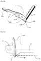
- the frame 1 is positioned immediately behind the tray, preferably at the level of its cover, and in front of the rear axle 2 of the vehicle which carries, for its part, longitudinal arms 21 for fixing to the body, as illustrated in the Figure 3 .
- the invention aims to reinforce the frame 1 of the tank while presenting a selective impact zone for the rear axle 2 in the event of a rear-end collision.
- each of the bent lateral connection zones has a nozzle 14 projecting towards the rear, formed of the joining of at least two protrusions 110, 120 carried by the respective ends of the longitudinal beams 11a, 11b and the crosspiece 12.
- the rebate of the two side noses 14 has a divergent inclination a between 120° and 150° relative to the vertical plane passing through the axis X of the crosspiece 12, as illustrated by the Figure 2C .
- each nozzle 14 further comprises a projection 130 also carried by the support element 13 of the tray associated with it.
- the protrusions 110 of the longitudinal members 11a, 11b extend below the protrusions 120 of the crosspiece 12 while the protrusions 130 of the tray support elements 13 extend above the protrusions 120 of the crosspiece 12, as illustrated by the figures 2A And 2B .
- the invention also provides that the rear axle 2 carries two symmetrical stops 22a, 22b extending forwards towards the noses 14 of the frame 1 of the tank. These stops are mounted between deformable longitudinal arms 21 for fixing the rear axle 2 to the body of the vehicle, as illustrated by the Figure 3 .
- the plates 13 of the tray support elements delimit between them a slot 15 (visible on the figures 1 , 2B And 4B ), intended to receive, in the event of an impact, a yoke 23 carried by each of the deformable longitudinal arms 21 of the rear axle 2, as illustrated by the figures 4A And 4B .
Landscapes
- Engineering & Computer Science (AREA)
- Chemical & Material Sciences (AREA)
- Combustion & Propulsion (AREA)
- Transportation (AREA)
- Mechanical Engineering (AREA)
- Body Structure For Vehicles (AREA)
- Arrangement Or Mounting Of Propulsion Units For Vehicles (AREA)
- Cooling, Air Intake And Gas Exhaust, And Fuel Tank Arrangements In Propulsion Units (AREA)
- Battery Mounting, Suspending (AREA)
Description
L'invention s'applique au domaine de la protection de la batterie de traction équipant les véhicules automobiles à motorisation électrique.The invention applies to the field of protection of the traction battery fitted to motor vehicles with electric motors.
Les véhicules électriques sont équipés de batteries destinées à leur assurer une autonomie suffisante. Toutefois, ces batteries sont notablement plus lourdes, plus encombrantes et à plus haute tension que les batteries ordinaires embarquées sur les modèles équivalents de véhicules à motorisation thermique.Electric vehicles are equipped with batteries intended to provide them with sufficient autonomy. However, these batteries are notably heavier, more bulky and have a higher voltage than ordinary batteries on board equivalent models of thermally powered vehicles.
En général, les modules des batteries de traction des véhicules électriques sont conditionnés et enfermés dans des bacs implantés sous le plancher et montés entre l'avant du véhicule et le plancher d'assise arrière où ils occupent tout l'espace disponible qui est libéré par l'absence de réservoir de carburant.In general, the traction battery modules of electric vehicles are packaged and enclosed in trays located under the floor and mounted between the front of the vehicle and the rear seat floor where they occupy all the available space which is freed by the absence of a fuel tank.
En cas de choc sur un véhicule électrique, les conséquences de l'endommagement de la batterie sont plus sérieuses et plus importantes que sur un véhicule thermique.In the event of an impact on an electric vehicle, the consequences of battery damage are more serious and more significant than on a thermal vehicle.
En particulier, un impact à l'arrière du véhicule peut provoquer un recul non maîtrisé du train arrière (par rupture des organes de fixation sur la caisse ou par contact direct de la traverse de train sur le couvercle du bac de batterie sous chargement) et entraîner une détérioration des modules de la batterie et, par suite, un risque d'incendie.In particular, an impact at the rear of the vehicle can cause uncontrolled recoil of the rear axle (by breakage of the fixing members on the body or by direct contact of the axle cross member on the cover of the battery tray under load) and cause damage to the battery modules and, consequently, a risk of fire.
Par conséquent, les batteries de traction des véhicules électriques nécessitent des moyens de protection renforcés et adaptés car ce type de véhicule doit répondre à des contraintes plus sévères, en particulier aux USA, pour assurer la sécurité des personnes en cas d'accident, et notamment, pour préserver l'intégrité des modules de batterie en cas de choc et éviter ainsi les courts-circuits.Consequently, the traction batteries of electric vehicles require reinforced and adapted means of protection because this type of vehicle must meet more severe constraints, particularly in the USA, to ensure the safety of people in the event of an accident, and in particular, to preserve the integrity of the battery modules in the event of an impact and thus avoid short circuits.
Généralement, les bacs supportant les modules de batterie sont pourvus d'une armature au moins partiellement périphérique, comprenant deux longerons latéraux raccordés, via une liaison coudée, à une traverse arrière.Generally, the trays supporting the battery modules are provided with an at least partially peripheral frame, comprising two side rails connected, via an elbow connection, to a rear crosspiece.
Le brevet
Le brevet
Le document
Cependant, les éléments de châssis proposés dans ces brevets ne sont, ni conçus, ni adaptés pour renforcer l'armature structurante du bac de batterie de façon à permettre, sans pièce intermédiaire, d'augmenter son potentiel d'absorption d'énergie et de préserver ainsi la batterie de traction en cas d'impacts sur le train arrière du véhicule.However, the chassis elements proposed in these patents are neither designed nor adapted to reinforce the structuring frame of the battery tray so as to allow, without an intermediate part, to increase its potential for energy absorption and thus preserving the traction battery in the event of impacts on the rear axle of the vehicle.
Dans ce contexte spécifique, l'invention vise à résoudre les problèmes techniques mentionnés ci-dessus en proposant un dispositif de protection assurant, à la fois, une cinématique de déformation sélective du train arrière du véhicule et, une absorption efficace des chocs par l'armature du bac de batterie.In this specific context, the invention aims to resolve the technical problems mentioned above by proposing a protective device ensuring, at the same time, selective deformation kinematics of the rear axle of the vehicle and effective absorption of shocks by the frame of the battery tray.
Ce but est atteint au moyen d'un dispositif de protection de la batterie d'un véhicule électrique vis-à-vis des impacts du train arrière, ladite batterie étant conditionnée dans un bac pourvu d'une armature comprenant, de part et d'autre du bac, un longeron dont l'extrémité est raccordée, via une zone de liaison coudée, à l'extrémité latérale en regard d'une traverse arrière et dont le flanc extérieur est pourvu d'au moins un élément de support du bac sur la caisse du véhicule, caractérisé en ce que chaque zone de liaison comporte un bec en saillie vers l'arrière formé de la solidarisation d'au moins deux excroissances portées par les extrémités respectives du longeron et de la traverse.This goal is achieved by means of a device for protecting the battery of an electric vehicle against impacts from the rear axle, said battery being packaged in a container provided with a frame comprising, on both sides other of the tray, a spar whose end is connected, via a bent connection zone, to the lateral end facing a rear cross member and whose outer side is provided with at least one tray support element on the body of the vehicle, characterized in that each connection zone comprises a nozzle projecting towards the rear formed by the joining of at least two protrusions carried by the respective ends of the spar and crossmember.
Selon une caractéristique avantageuse, les excroissances des longerons se prolongent au-dessous des excroissances de la traverse.According to an advantageous characteristic, the protrusions of the spars extend below the protrusions of the crosspiece.
Selon une autre caractéristique, les becs comprennent en outre des excroissances portées par les éléments de support du bac.According to another characteristic, the nozzles further comprise protrusions carried by the support elements of the tray.
De préférence, les excroissances des éléments de support du bac se prolongent au-dessus des excroissances de la traverse.Preferably, the protrusions of the support elements of the tray extend above the protrusions of the crosspiece.
Selon encore une autre caractéristique, les becs présentent une inclinaison divergente comprise entre 120° et 150° par rapport au plan vertical passant par l'axe de la traverse.According to yet another characteristic, the slats have a divergent inclination of between 120° and 150° relative to the vertical plane passing through the axis of the crosspiece.
Selon une variante de réalisation de l'invention, le train arrière porte deux butées symétriques s'étendant vers l'avant en direction des becs de l'armature.According to a variant embodiment of the invention, the rear axle carries two symmetrical stops extending forwards towards the noses of the frame.
Selon une autre variante, les éléments de support du bac portent chacun deux platines sensiblement horizontales de fixation sur la caisse du véhicule.According to another variant, the tray support elements each carry two substantially horizontal mounting plates on the body of the vehicle.
De préférence, ces platines délimitent entre elles un créneau destiné à recevoir, en cas d'impact, une chape portée par un bras longitudinal déformable de fixation du train arrière.Preferably, these plates define between them a slot intended to receive, in the event of an impact, a yoke carried by a deformable longitudinal arm for fixing the rear axle.
Selon encore une autre variante de réalisation, les butées sont montées entre les bras longitudinaux déformables de fixation du train arrière.According to yet another alternative embodiment, the stops are mounted between the deformable longitudinal arms for fixing the rear axle.
Un autre objet de l'invention est un véhicule électrique équipé d'une batterie conditionnée dans un bac pourvu d'un dispositif de protection contre les impacts présentant les caractéristiques définies ci-dessus.Another object of the invention is an electric vehicle equipped with a battery packaged in a container provided with a protection device against impacts having the characteristics defined above.
Le dispositif de l'invention permet de préserver les modules de batterie de la batterie de traction vis-à-vis des éventuelles déformations résultant d'une collision par l'arrière à grande vitesse avec un autre véhicule.The device of the invention makes it possible to preserve the battery modules of the traction battery against possible deformations resulting from a high-speed rear-end collision with another vehicle.
Le dispositif de l'invention s'intègre parfaitement au design de l'armature du bac de batterie et offre un niveau de sécurité maximum même pour les chocs arrières les plus sévères.The device of the invention integrates perfectly with the design of the battery tray frame and offers a maximum level of safety even for the most severe rear impacts.
En particulier, le dispositif de l'invention est conforme aux normes américaines qui imposent un recouvrement de la zone d'impact d'au moins 70% du train arrière pour un choc avec un véhicule pesant environ 1,4 tonnes et roulant à 80km/h.In particular, the device of the invention complies with American standards which require the impact zone to be covered by at least 70% of the rear axle for an impact with a vehicle weighing approximately 1.4 tonnes and traveling at 80 km/h. h.
La cinématique de déformation programmée (par flambage) du bras longitudinal de train arrière permet de localiser très précisément sa zone d'impact sur la traverse de l'armature du bac de la batterie qui a été renforcée à cet effet par la présence d'un bec.The programmed deformation kinematics (by buckling) of the rear axle longitudinal arm makes it possible to very precisely locate its impact zone on the crosspiece of the battery tray frame which has been reinforced for this purpose by the presence of a beak.
Plus précisément, cette déformation qui ne se produit que sous des contraintes résultant d'un choc arrière à grande vitesse permet un recul maîtrisé de la traverse de train arrière sans rupture de la liaison avec la caisse du véhicule jusqu'à venir en butée vers l'avant contre le bec de renfort de l'armature du bac de batterie.More precisely, this deformation which only occurs under stresses resulting from a rear impact at high speed allows controlled recoil of the rear axle crossmember without breaking the connection with the body of the vehicle until it comes to a stop towards the front against the reinforcing beak of the battery tray frame.
Un essai a été réalisé avec un charriot impacteur de 1368 kg lancé à plus de 80 km/h générant une énergie cinétqiue incidente d'environ 346 kilojoules.A test was carried out with a 1368 kg impactor cart launched at more than 80 km/h generating an incident kinetic energy of approximately 346 kilojoules.
Selon l'invention, le contact de butée se produit ainsi de façon déportée, par exemple, via le support de la butée de talonnage, et contribue à maintenir la traverse éloignée de la batterie.According to the invention, the stop contact thus occurs in an offset manner, for example, via the support of the bottoming stop, and contributes to keeping the crosspiece away from the battery.
Par conséquent, grâce à l'invention, l'armature du bac de la batterie est capable d'absorber l'énergie cinétique de l'impact sans déformer le bac en maintenant la traverse de train arrière à distance tout en limitant la décélération transmise aux modules via l'armature.Consequently, thanks to the invention, the frame of the battery tray is capable of absorbing the kinetic energy of the impact without deforming the tray by keeping the rear axle crossmember at a distance while limiting the deceleration transmitted to the modules via the frame.
Toujours grâce à l'invention, le train arrière, destiné aux véhicules électriques, est adapté et combiné à l'armature renforcée du bac de batterie et son mode spécifique de déformation (notamment, au niveau de ses bras longitudinaux) permet d'augmenter le potentiel d'absorption d'énergie en sécurisant ainsi les modules de la batterie.Still thanks to the invention, the rear axle, intended for electric vehicles, is adapted and combined with the reinforced frame of the battery tray and its specific mode of deformation (in particular, at the level of its longitudinal arms) makes it possible to increase the energy absorption potential thus securing the battery modules.
En outre, le dispositif de protection de l'invention est transposable aux différents empattements des plateformes modulaires dédiées aux lignes de production des véhicules et, en particulier, de celles destinées aux véhicules électriques (dites eCMP pour « electric Common Modular Platform »). In addition, the protection device of the invention can be transposed to the different wheelbases of modular platforms dedicated to vehicle production lines and, in particular, those intended for electric vehicles (known as eCMP for “ electric Common Modular Platform ”) .
D'autres caractéristiques et avantages de l'invention ressortiront à la lecture de la description qui va suivre, en référence aux figures annexées et détaillées ci-après.
- [
Fig. 1 ] est une vue en perspective de l'armature du bac de batterie équipé d'un mode de réalisation du dispositif de protection selon l'invention. - [
Fig. 2A ] est une vue partielle de dessus par l'avant du dispositif de protection de lafigure 1 . - [
Fig. 2B ] est une vue partielle de dessus par l'arrière du dispositif de protection de lafigure 1 . - [
Fig. 2C ] est une vue partielle de dessus du dispositif de protection de lafigure 1 . - [
Fig. 3 ] est une vue en perspective du train arrière d'un véhicule équipé du dispositif de protection selon l'invention. - [
Fig. 4A ] est une vue d'ensemble en perspective du dispositif desfigures 1 et3 après impact sur l'arrière gauche du véhicule. - [
Fig. 4B ] est une vue partielle de dessus et en perspective du dispositif desfigures 1 et3 après impact sur l'arrière gauche du véhicule.
- [
Fig. 1 ] is a perspective view of the frame of the battery tray equipped with an embodiment of the protection device according to the invention. - [
Fig. 2A ] is a partial top view from the front of the safety protection devicefigure 1 . - [
Fig. 2B ] is a partial top view from the rear of the safety protection devicefigure 1 . - [
Fig. 2C ] is a partial top view of the protection device of thefigure 1 . - [
Fig. 3 ] is a perspective view of the rear axle of a vehicle equipped with the protection device according to the invention. - [
Fig. 4A ] is an overview in perspective of the system offigures 1 And3 after impact on the left rear of the vehicle. - [
Fig. 4B ] is a partial top and perspective view of the device of thefigures 1 And3 after impact on the left rear of the vehicle.
Pour plus de clarté, les éléments identiques ou similaires sont repérés par des signes de référence identiques sur l'ensemble des figures.For greater clarity, identical or similar elements are identified by identical reference signs throughout the figures.
Naturellement, les modes de mise en oeuvre de l'invention illustrés par les figures présentées ci-dessus et décrites ci-après, ne sont donnés qu'à titre d'exemples non limitatifs. Il est explicitement prévu que l'on puisse proposer et combiner entre eux différents modes pour en proposer d'autres.Naturally, the modes of implementation of the invention illustrated by the figures presented above and described below, are given only by way of non-limiting examples. It is explicitly planned that different modes can be proposed and combined to offer others.
Le dispositif de l'invention est destiné à la protection des modules de la batterie de traction des véhicules électriques qui sont conditionnés et enfermés dans des bacs (non représentés) implantés dans un espace 10 situé sous le plancher entre l'avant du véhicule et le plancher d'assise arrière.The device of the invention is intended for the protection of the traction battery modules of electric vehicles which are packaged and enclosed in bins (not shown) located in a
Un tel bac est pourvu d'une armature 1, au moins partiellement périphérique, comprenant, de part et d'autre du bac, un longeron 11a, 11b. Les extrémités de ces longerons sont raccordées, via des zones de liaison coudées, aux extrémités latérales en regard d'une traverse arrière 12. Le flanc extérieur des longerons 11a, 11b est pourvu d'au moins un, et ici de deux éléments de support du bac sur la caisse du véhicule, comme illustré par la
Les deux éléments latéraux de support du bac sont formés de deux platines 13 sensiblement horizontales dans lesquels sont ménagés des orifices pour la pose d'organes (non représentés) de fixation sur la caisse du véhicule.The two lateral support elements of the tray are formed of two substantially
L'armature 1 est positionnée immédiatement derrière le bac, de préférence au niveau de son couvercle, et devant le train arrière 2 du véhicule qui porte, quant à lui, des bras longitudinaux 21 de fixation sur la caisse, comme illustré sur la
L'invention a pour objectif de renforcer l'armature 1 du bac tout en présentant une zone sélective d'impact pour le train arrière 2 en cas de collision par l'arrière.The invention aims to reinforce the
A cet effet et comme illustré par les
La feuillure des deux becs latéraux 14 présente une inclinaison divergente a comprise entre 120° et 150° par rapport au plan vertical passant par l'axe X de la traverse 12, comme illustré par la
Dans le mode de réalisation représenté sur les figures, chaque bec 14 comprend, en outre, une excroissance 130 portée aussi par l'élément 13 de support du bac qui lui est associé.In the embodiment shown in the figures, each
De préférence, les excroissances 110 des longerons 11a, 11b se prolongent au-dessous des excroissances 120 de la traverse 12 tandis que les excroissances 130 des éléments 13 de support du bac se prolongent au-dessus des excroissances 120 de la traverse 12, comme illustré par les
L'invention prévoit également que le train arrière 2 porte deux butées symétriques 22a, 22b s'étendant vers l'avant en direction des becs 14 de l'armature 1 du bac. Ces butées sont montées entre des bras longitudinaux 21 déformables de fixation du train arrière 2 sur la caisse du véhicule, comme illustré par la
Les platines 13 des éléments de support du bac délimitent entre elles un créneau 15 (visible sur les
Claims (10)
- Device for protecting the battery of an electric vehicle against impacts on the rear axle (2), said battery being packaged in a container provided with a frame (1) comprising, on either side of the tray, a spar (11a, 11b) whose end is connected, via an angled connection zone, to the lateral end opposite a rear crossmember (12) and whose outer side is provided with at least one support element of the tray, characterized in that each connecting zone comprises a beak (14) projecting towards the rear formed by the joining together of at least two protrusions (110, 120) carried by the respective ends of the spar (11a , 11b) and the crosspiece (12).
- Protective device according to Claim 1, characterized in that the protuberances (110) of the side members (11a, 11b) extend below the protuberances (120) of the crosspiece (12).
- Protective device according to one of the preceding claims, characterized in that the said spouts (14) further comprise protrusions (130) carried by the support elements of the tray.
- Protective device according to the preceding claim, characterized in that the protuberances (130) of the support elements of the tray extend above the protrusions (120) of the crosspiece (12).
- Protective device according to one of the preceding claims, characterized in that the said jaws (14) have a divergent inclination of between 120° and 150° with respect to the vertical plane passing through the axis of the crosspiece (12).
- Protective device according to one of the preceding claims, characterized in that the rear axle (2) carries two symmetrical stops (22a, 22b) extending forwards in the direction of the lugs (14) of the armature (1).
- Protective device according to one of the preceding claims, characterized in that the tray support elements each carry two substantially horizontal mounting plates (13) on the body of the vehicle.
- Protective device according to the preceding claim, characterized in that the said plates (13) delimit between them a slot (15) intended to receive, in the event of impact, a yoke (23) carried by a longitudinal arm (21) deformable by rear axle mounting (2).
- Protective device according to Claims 6 and 8, characterized in that the said stops (22a, 22b) are mounted between the deformable longitudinal arms (21) for fixing the rear axle (2).
- Electric vehicle equipped with a battery packaged in a container provided with a device for protection against impacts according to one of the preceding claims.
Applications Claiming Priority (2)
| Application Number | Priority Date | Filing Date | Title |
|---|---|---|---|
| FR1913070A FR3103450B1 (en) | 2019-11-22 | 2019-11-22 | PROTECTION DEVICE FOR THE TRACTION BATTERY OF ELECTRIC VEHICLES |
| PCT/FR2020/051851 WO2021099704A1 (en) | 2019-11-22 | 2020-10-16 | Device for protecting the traction battery of electric vehicles |
Publications (3)
| Publication Number | Publication Date |
|---|---|
| EP4061659A1 EP4061659A1 (en) | 2022-09-28 |
| EP4061659B1 true EP4061659B1 (en) | 2023-11-29 |
| EP4061659B8 EP4061659B8 (en) | 2024-01-03 |
Family
ID=69811067
Family Applications (1)
| Application Number | Title | Priority Date | Filing Date |
|---|---|---|---|
| EP20803216.9A Active EP4061659B8 (en) | 2019-11-22 | 2020-10-16 | Device for protecting the traction battery of electric vehicles |
Country Status (4)
| Country | Link |
|---|---|
| EP (1) | EP4061659B8 (en) |
| CN (1) | CN114728571A (en) |
| FR (1) | FR3103450B1 (en) |
| WO (1) | WO2021099704A1 (en) |
Families Citing this family (1)
| Publication number | Priority date | Publication date | Assignee | Title |
|---|---|---|---|---|
| FR3127463B1 (en) | 2021-09-29 | 2024-08-09 | Psa Automobiles Sa | MOTOR VEHICLE WITH REAR IMPACT FORCE RESUMPTION BY A TRACTION BATTERY TRAY |
Family Cites Families (7)
| Publication number | Priority date | Publication date | Assignee | Title |
|---|---|---|---|---|
| JP5549334B2 (en) * | 2010-04-07 | 2014-07-16 | 日産自動車株式会社 | Rear structure of electric vehicle body |
| JP5071538B2 (en) * | 2010-09-03 | 2012-11-14 | トヨタ自動車株式会社 | Battery mounting structure for vehicles |
| FR2972169B1 (en) | 2011-03-01 | 2013-11-08 | Courb | MODULAR CHASSIS WITH HANGERS HANGERS FOR ELECTRIC VEHICLES |
| JP5790365B2 (en) * | 2011-09-20 | 2015-10-07 | トヨタ自動車株式会社 | Vehicle battery mounting structure |
| FR3000459B1 (en) | 2012-12-28 | 2016-05-13 | Courb | CHASSIS FOR TERRESTRIAL VEHICLE AND METHOD FOR MANUFACTURING THE SAME |
| DE102013005571A1 (en) * | 2013-03-30 | 2014-10-02 | Daimler Ag | Support frame for holding at least one energy storage and / or a drive component of a motor vehicle |
| DE102015013533B3 (en) * | 2015-10-19 | 2016-09-15 | Audi Ag | Subframe for a vehicle rear axle |
-
2019
- 2019-11-22 FR FR1913070A patent/FR3103450B1/en not_active Expired - Fee Related
-
2020
- 2020-10-16 CN CN202080080826.7A patent/CN114728571A/en active Pending
- 2020-10-16 WO PCT/FR2020/051851 patent/WO2021099704A1/en unknown
- 2020-10-16 EP EP20803216.9A patent/EP4061659B8/en active Active
Also Published As
| Publication number | Publication date |
|---|---|
| EP4061659B8 (en) | 2024-01-03 |
| EP4061659A1 (en) | 2022-09-28 |
| WO2021099704A1 (en) | 2021-05-27 |
| FR3103450A1 (en) | 2021-05-28 |
| FR3103450B1 (en) | 2021-11-19 |
| CN114728571A (en) | 2022-07-08 |
Similar Documents
| Publication | Publication Date | Title |
|---|---|---|
| EP2834104B1 (en) | Chassis of a motor vehicle including a means for absorbing a frontal impact | |
| EP0854818B1 (en) | Ultra-light road vehicle | |
| EP2598394B1 (en) | Car frame with heightened seat cross-beam | |
| EP2782814B1 (en) | Compact urban vehicle | |
| FR3105153A1 (en) | REAR PART OF MOTOR VEHICLE BODY STRUCTURE EQUIPPED WITH SPRINGS AND SPRINGS | |
| WO2010031943A1 (en) | Storage module, and vehicle including same | |
| EP4061659B1 (en) | Device for protecting the traction battery of electric vehicles | |
| EP0574281B1 (en) | Motor vehicle with electric propulsion with a body which is derived with very few modifications from the body of a vehicle with combustion engine | |
| EP1693283B1 (en) | Front structure for a motor vehicle | |
| EP2911931B1 (en) | Arrangement for securing a spare wheel well of a motor vehicle | |
| FR3038574A1 (en) | VEHICLE STRUCTURE COMPRISING A REINFORCING ELEMENT AND VEHICLE COMPRISING SUCH A STRUCTURE | |
| WO2012066247A1 (en) | Arrangement of a high-voltage battery in a hybrid automobile | |
| WO2015189504A1 (en) | Arrangement of a dashboard trim element of a motor vehicle on a supporting element of said dashboard | |
| FR2885575A1 (en) | Load stop device for e.g. minivan, has transversal part blocking load coming to hit it in case of violent impact, where transversal and inclined parts tilt and pivot towards base, in case of impact of load against transversal part | |
| EP2822840B1 (en) | Motor vehicle body with cable-stiffened cowl region | |
| EP2532547A1 (en) | Frame structure for supporting a passenger compartment to form an electrically-powered automobile and automobile comprising such a frame structure | |
| WO2022037902A1 (en) | Vehicle comprising a device for retaining the spare wheel | |
| EP4200194A1 (en) | Vehicle comprising a device for retaining the spare wheel | |
| FR2878209A1 (en) | Load stop device for e.g. minivan, has frame comprising collar that is toppled, by rotating towards rear volume of vehicle, with respect to axis, during violent impact of load against front and/or intermediate transversal portions | |
| EP2451694A1 (en) | Vehicle the chassis of which comprises at least two axial structures | |
| EP1847445B1 (en) | Front structure of automobile and corresponding method | |
| FR3139106A1 (en) | Motor vehicle structure with ejectable cradle | |
| EP3386779B1 (en) | Rear axle assembly and device for securing same | |
| FR3138644A1 (en) | Motor vehicle structure with loading floor | |
| FR3134783A1 (en) | REAR CRADLE WITH REINFORCED RESISTANCE, FOR A LAND VEHICLE |
Legal Events
| Date | Code | Title | Description |
|---|---|---|---|
| STAA | Information on the status of an ep patent application or granted ep patent |
Free format text: STATUS: UNKNOWN |
|
| STAA | Information on the status of an ep patent application or granted ep patent |
Free format text: STATUS: THE INTERNATIONAL PUBLICATION HAS BEEN MADE |
|
| PUAI | Public reference made under article 153(3) epc to a published international application that has entered the european phase |
Free format text: ORIGINAL CODE: 0009012 |
|
| STAA | Information on the status of an ep patent application or granted ep patent |
Free format text: STATUS: REQUEST FOR EXAMINATION WAS MADE |
|
| 17P | Request for examination filed |
Effective date: 20220406 |
|
| AK | Designated contracting states |
Kind code of ref document: A1 Designated state(s): AL AT BE BG CH CY CZ DE DK EE ES FI FR GB GR HR HU IE IS IT LI LT LU LV MC MK MT NL NO PL PT RO RS SE SI SK SM TR |
|
| DAV | Request for validation of the european patent (deleted) | ||
| DAX | Request for extension of the european patent (deleted) | ||
| GRAP | Despatch of communication of intention to grant a patent |
Free format text: ORIGINAL CODE: EPIDOSNIGR1 |
|
| STAA | Information on the status of an ep patent application or granted ep patent |
Free format text: STATUS: GRANT OF PATENT IS INTENDED |
|
| INTG | Intention to grant announced |
Effective date: 20230720 |
|
| GRAS | Grant fee paid |
Free format text: ORIGINAL CODE: EPIDOSNIGR3 |
|
| GRAA | (expected) grant |
Free format text: ORIGINAL CODE: 0009210 |
|
| STAA | Information on the status of an ep patent application or granted ep patent |
Free format text: STATUS: THE PATENT HAS BEEN GRANTED |
|
| REG | Reference to a national code |
Ref country code: DE Ref legal event code: R084 Ref document number: 602020022040 Country of ref document: DE |
|
| REG | Reference to a national code |
Ref country code: DE Ref legal event code: R081 Ref document number: 602020022040 Country of ref document: DE Owner name: STELLANTIS AUTO SAS, FR Free format text: FORMER OWNER: PSA AUTOMOBILES SA, POISSY, FR |
|
| AK | Designated contracting states |
Kind code of ref document: B1 Designated state(s): AL AT BE BG CH CY CZ DE DK EE ES FI FR GB GR HR HU IE IS IT LI LT LU LV MC MK MT NL NO PL PT RO RS SE SI SK SM TR |
|
| REG | Reference to a national code |
Ref country code: GB Ref legal event code: FG4D Free format text: NOT ENGLISH |
|
| REG | Reference to a national code |
Ref country code: CH Ref legal event code: EP |
|
| RAP4 | Party data changed (patent owner data changed or rights of a patent transferred) |
Owner name: STELLANTIS AUTO SAS |
|
| REG | Reference to a national code |
Ref country code: DE Ref legal event code: R096 Ref document number: 602020022040 Country of ref document: DE |
|
| REG | Reference to a national code |
Ref country code: CH Ref legal event code: PK Free format text: RECTIFICATION B8 |
|
| REG | Reference to a national code |
Ref country code: IE Ref legal event code: FG4D Free format text: LANGUAGE OF EP DOCUMENT: FRENCH |
|
| REG | Reference to a national code |
Ref country code: GB Ref legal event code: 746 Effective date: 20231212 |
|
| REG | Reference to a national code |
Ref country code: LT Ref legal event code: MG9D |
|
| REG | Reference to a national code |
Ref country code: NL Ref legal event code: MP Effective date: 20231129 |
|
| PG25 | Lapsed in a contracting state [announced via postgrant information from national office to epo] |
Ref country code: GR Free format text: LAPSE BECAUSE OF FAILURE TO SUBMIT A TRANSLATION OF THE DESCRIPTION OR TO PAY THE FEE WITHIN THE PRESCRIBED TIME-LIMIT Effective date: 20240301 |
|
| PG25 | Lapsed in a contracting state [announced via postgrant information from national office to epo] |
Ref country code: IS Free format text: LAPSE BECAUSE OF FAILURE TO SUBMIT A TRANSLATION OF THE DESCRIPTION OR TO PAY THE FEE WITHIN THE PRESCRIBED TIME-LIMIT Effective date: 20240329 |
|
| PG25 | Lapsed in a contracting state [announced via postgrant information from national office to epo] |
Ref country code: LT Free format text: LAPSE BECAUSE OF FAILURE TO SUBMIT A TRANSLATION OF THE DESCRIPTION OR TO PAY THE FEE WITHIN THE PRESCRIBED TIME-LIMIT Effective date: 20231129 |
|
| PG25 | Lapsed in a contracting state [announced via postgrant information from national office to epo] |
Ref country code: ES Free format text: LAPSE BECAUSE OF FAILURE TO SUBMIT A TRANSLATION OF THE DESCRIPTION OR TO PAY THE FEE WITHIN THE PRESCRIBED TIME-LIMIT Effective date: 20231129 |
|
| PG25 | Lapsed in a contracting state [announced via postgrant information from national office to epo] |
Ref country code: LT Free format text: LAPSE BECAUSE OF FAILURE TO SUBMIT A TRANSLATION OF THE DESCRIPTION OR TO PAY THE FEE WITHIN THE PRESCRIBED TIME-LIMIT Effective date: 20231129 Ref country code: IS Free format text: LAPSE BECAUSE OF FAILURE TO SUBMIT A TRANSLATION OF THE DESCRIPTION OR TO PAY THE FEE WITHIN THE PRESCRIBED TIME-LIMIT Effective date: 20240329 Ref country code: GR Free format text: LAPSE BECAUSE OF FAILURE TO SUBMIT A TRANSLATION OF THE DESCRIPTION OR TO PAY THE FEE WITHIN THE PRESCRIBED TIME-LIMIT Effective date: 20240301 Ref country code: ES Free format text: LAPSE BECAUSE OF FAILURE TO SUBMIT A TRANSLATION OF THE DESCRIPTION OR TO PAY THE FEE WITHIN THE PRESCRIBED TIME-LIMIT Effective date: 20231129 Ref country code: BG Free format text: LAPSE BECAUSE OF FAILURE TO SUBMIT A TRANSLATION OF THE DESCRIPTION OR TO PAY THE FEE WITHIN THE PRESCRIBED TIME-LIMIT Effective date: 20240229 |
|
| REG | Reference to a national code |
Ref country code: AT Ref legal event code: MK05 Ref document number: 1635779 Country of ref document: AT Kind code of ref document: T Effective date: 20231129 |
|
| PG25 | Lapsed in a contracting state [announced via postgrant information from national office to epo] |
Ref country code: NL Free format text: LAPSE BECAUSE OF FAILURE TO SUBMIT A TRANSLATION OF THE DESCRIPTION OR TO PAY THE FEE WITHIN THE PRESCRIBED TIME-LIMIT Effective date: 20231129 |
|
| PG25 | Lapsed in a contracting state [announced via postgrant information from national office to epo] |
Ref country code: SE Free format text: LAPSE BECAUSE OF FAILURE TO SUBMIT A TRANSLATION OF THE DESCRIPTION OR TO PAY THE FEE WITHIN THE PRESCRIBED TIME-LIMIT Effective date: 20231129 Ref country code: RS Free format text: LAPSE BECAUSE OF FAILURE TO SUBMIT A TRANSLATION OF THE DESCRIPTION OR TO PAY THE FEE WITHIN THE PRESCRIBED TIME-LIMIT Effective date: 20231129 Ref country code: PL Free format text: LAPSE BECAUSE OF FAILURE TO SUBMIT A TRANSLATION OF THE DESCRIPTION OR TO PAY THE FEE WITHIN THE PRESCRIBED TIME-LIMIT Effective date: 20231129 Ref country code: NO Free format text: LAPSE BECAUSE OF FAILURE TO SUBMIT A TRANSLATION OF THE DESCRIPTION OR TO PAY THE FEE WITHIN THE PRESCRIBED TIME-LIMIT Effective date: 20240229 Ref country code: NL Free format text: LAPSE BECAUSE OF FAILURE TO SUBMIT A TRANSLATION OF THE DESCRIPTION OR TO PAY THE FEE WITHIN THE PRESCRIBED TIME-LIMIT Effective date: 20231129 Ref country code: LV Free format text: LAPSE BECAUSE OF FAILURE TO SUBMIT A TRANSLATION OF THE DESCRIPTION OR TO PAY THE FEE WITHIN THE PRESCRIBED TIME-LIMIT Effective date: 20231129 Ref country code: HR Free format text: LAPSE BECAUSE OF FAILURE TO SUBMIT A TRANSLATION OF THE DESCRIPTION OR TO PAY THE FEE WITHIN THE PRESCRIBED TIME-LIMIT Effective date: 20231129 |
|
| PG25 | Lapsed in a contracting state [announced via postgrant information from national office to epo] |
Ref country code: DK Free format text: LAPSE BECAUSE OF FAILURE TO SUBMIT A TRANSLATION OF THE DESCRIPTION OR TO PAY THE FEE WITHIN THE PRESCRIBED TIME-LIMIT Effective date: 20231129 |
|
| PG25 | Lapsed in a contracting state [announced via postgrant information from national office to epo] |
Ref country code: AT Free format text: LAPSE BECAUSE OF FAILURE TO SUBMIT A TRANSLATION OF THE DESCRIPTION OR TO PAY THE FEE WITHIN THE PRESCRIBED TIME-LIMIT Effective date: 20231129 Ref country code: CZ Free format text: LAPSE BECAUSE OF FAILURE TO SUBMIT A TRANSLATION OF THE DESCRIPTION OR TO PAY THE FEE WITHIN THE PRESCRIBED TIME-LIMIT Effective date: 20231129 |
|
| PG25 | Lapsed in a contracting state [announced via postgrant information from national office to epo] |
Ref country code: SK Free format text: LAPSE BECAUSE OF FAILURE TO SUBMIT A TRANSLATION OF THE DESCRIPTION OR TO PAY THE FEE WITHIN THE PRESCRIBED TIME-LIMIT Effective date: 20231129 |
|
| PG25 | Lapsed in a contracting state [announced via postgrant information from national office to epo] |
Ref country code: SM Free format text: LAPSE BECAUSE OF FAILURE TO SUBMIT A TRANSLATION OF THE DESCRIPTION OR TO PAY THE FEE WITHIN THE PRESCRIBED TIME-LIMIT Effective date: 20231129 Ref country code: SK Free format text: LAPSE BECAUSE OF FAILURE TO SUBMIT A TRANSLATION OF THE DESCRIPTION OR TO PAY THE FEE WITHIN THE PRESCRIBED TIME-LIMIT Effective date: 20231129 Ref country code: RO Free format text: LAPSE BECAUSE OF FAILURE TO SUBMIT A TRANSLATION OF THE DESCRIPTION OR TO PAY THE FEE WITHIN THE PRESCRIBED TIME-LIMIT Effective date: 20231129 Ref country code: IT Free format text: LAPSE BECAUSE OF FAILURE TO SUBMIT A TRANSLATION OF THE DESCRIPTION OR TO PAY THE FEE WITHIN THE PRESCRIBED TIME-LIMIT Effective date: 20231129 Ref country code: EE Free format text: LAPSE BECAUSE OF FAILURE TO SUBMIT A TRANSLATION OF THE DESCRIPTION OR TO PAY THE FEE WITHIN THE PRESCRIBED TIME-LIMIT Effective date: 20231129 Ref country code: DK Free format text: LAPSE BECAUSE OF FAILURE TO SUBMIT A TRANSLATION OF THE DESCRIPTION OR TO PAY THE FEE WITHIN THE PRESCRIBED TIME-LIMIT Effective date: 20231129 Ref country code: CZ Free format text: LAPSE BECAUSE OF FAILURE TO SUBMIT A TRANSLATION OF THE DESCRIPTION OR TO PAY THE FEE WITHIN THE PRESCRIBED TIME-LIMIT Effective date: 20231129 Ref country code: AT Free format text: LAPSE BECAUSE OF FAILURE TO SUBMIT A TRANSLATION OF THE DESCRIPTION OR TO PAY THE FEE WITHIN THE PRESCRIBED TIME-LIMIT Effective date: 20231129 |
|
| PG25 | Lapsed in a contracting state [announced via postgrant information from national office to epo] |
Ref country code: PT Free format text: LAPSE BECAUSE OF FAILURE TO SUBMIT A TRANSLATION OF THE DESCRIPTION OR TO PAY THE FEE WITHIN THE PRESCRIBED TIME-LIMIT Effective date: 20240401 |
|
| PG25 | Lapsed in a contracting state [announced via postgrant information from national office to epo] |
Ref country code: PT Free format text: LAPSE BECAUSE OF FAILURE TO SUBMIT A TRANSLATION OF THE DESCRIPTION OR TO PAY THE FEE WITHIN THE PRESCRIBED TIME-LIMIT Effective date: 20240401 |