EP4059627A1 - Hohlkörperformvorrichtung - Google Patents
Hohlkörperformvorrichtung Download PDFInfo
- Publication number
- EP4059627A1 EP4059627A1 EP20886632.7A EP20886632A EP4059627A1 EP 4059627 A1 EP4059627 A1 EP 4059627A1 EP 20886632 A EP20886632 A EP 20886632A EP 4059627 A1 EP4059627 A1 EP 4059627A1
- Authority
- EP
- European Patent Office
- Prior art keywords
- forming
- forming device
- dome
- leg
- pressing body
- Prior art date
- Legal status (The legal status is an assumption and is not a legal conclusion. Google has not performed a legal analysis and makes no representation as to the accuracy of the status listed.)
- Pending
Links
- 238000000465 moulding Methods 0.000 title 1
- 238000002407 reforming Methods 0.000 abstract description 14
- 238000002845 discoloration Methods 0.000 abstract description 5
- 230000007547 defect Effects 0.000 abstract description 4
- 238000000034 method Methods 0.000 description 16
- 238000012423 maintenance Methods 0.000 description 4
- 230000000630 rising effect Effects 0.000 description 4
- 230000007246 mechanism Effects 0.000 description 2
- 239000007769 metal material Substances 0.000 description 2
- 229910000838 Al alloy Inorganic materials 0.000 description 1
- 238000009825 accumulation Methods 0.000 description 1
- 230000000694 effects Effects 0.000 description 1
- 230000002708 enhancing effect Effects 0.000 description 1
- 238000010409 ironing Methods 0.000 description 1
- 239000000463 material Substances 0.000 description 1
- 229910052751 metal Inorganic materials 0.000 description 1
- 239000002184 metal Substances 0.000 description 1
- 230000002093 peripheral effect Effects 0.000 description 1
- 230000001954 sterilising effect Effects 0.000 description 1
- 238000004659 sterilization and disinfection Methods 0.000 description 1
Images


Classifications
-
- B—PERFORMING OPERATIONS; TRANSPORTING
- B21—MECHANICAL METAL-WORKING WITHOUT ESSENTIALLY REMOVING MATERIAL; PUNCHING METAL
- B21D—WORKING OR PROCESSING OF SHEET METAL OR METAL TUBES, RODS OR PROFILES WITHOUT ESSENTIALLY REMOVING MATERIAL; PUNCHING METAL
- B21D51/00—Making hollow objects
- B21D51/16—Making hollow objects characterised by the use of the objects
- B21D51/18—Making hollow objects characterised by the use of the objects vessels, e.g. tubs, vats, tanks, sinks, or the like
-
- B—PERFORMING OPERATIONS; TRANSPORTING
- B21—MECHANICAL METAL-WORKING WITHOUT ESSENTIALLY REMOVING MATERIAL; PUNCHING METAL
- B21D—WORKING OR PROCESSING OF SHEET METAL OR METAL TUBES, RODS OR PROFILES WITHOUT ESSENTIALLY REMOVING MATERIAL; PUNCHING METAL
- B21D51/00—Making hollow objects
- B21D51/16—Making hollow objects characterised by the use of the objects
- B21D51/26—Making hollow objects characterised by the use of the objects cans or tins; Closing same in a permanent manner
- B21D51/2669—Transforming the shape of formed can bodies; Forming can bodies from flattened tubular blanks; Flattening can bodies
-
- B—PERFORMING OPERATIONS; TRANSPORTING
- B21—MECHANICAL METAL-WORKING WITHOUT ESSENTIALLY REMOVING MATERIAL; PUNCHING METAL
- B21D—WORKING OR PROCESSING OF SHEET METAL OR METAL TUBES, RODS OR PROFILES WITHOUT ESSENTIALLY REMOVING MATERIAL; PUNCHING METAL
- B21D22/00—Shaping without cutting, by stamping, spinning, or deep-drawing
- B21D22/20—Deep-drawing
- B21D22/26—Deep-drawing for making peculiarly, e.g. irregularly, shaped articles
-
- B—PERFORMING OPERATIONS; TRANSPORTING
- B21—MECHANICAL METAL-WORKING WITHOUT ESSENTIALLY REMOVING MATERIAL; PUNCHING METAL
- B21D—WORKING OR PROCESSING OF SHEET METAL OR METAL TUBES, RODS OR PROFILES WITHOUT ESSENTIALLY REMOVING MATERIAL; PUNCHING METAL
- B21D22/00—Shaping without cutting, by stamping, spinning, or deep-drawing
- B21D22/20—Deep-drawing
- B21D22/28—Deep-drawing of cylindrical articles using consecutive dies
-
- B—PERFORMING OPERATIONS; TRANSPORTING
- B21—MECHANICAL METAL-WORKING WITHOUT ESSENTIALLY REMOVING MATERIAL; PUNCHING METAL
- B21D—WORKING OR PROCESSING OF SHEET METAL OR METAL TUBES, RODS OR PROFILES WITHOUT ESSENTIALLY REMOVING MATERIAL; PUNCHING METAL
- B21D22/00—Shaping without cutting, by stamping, spinning, or deep-drawing
- B21D22/20—Deep-drawing
- B21D22/30—Deep-drawing to finish articles formed by deep-drawing
-
- B—PERFORMING OPERATIONS; TRANSPORTING
- B21—MECHANICAL METAL-WORKING WITHOUT ESSENTIALLY REMOVING MATERIAL; PUNCHING METAL
- B21D—WORKING OR PROCESSING OF SHEET METAL OR METAL TUBES, RODS OR PROFILES WITHOUT ESSENTIALLY REMOVING MATERIAL; PUNCHING METAL
- B21D37/00—Tools as parts of machines covered by this subclass
- B21D37/10—Die sets; Pillar guides
-
- B—PERFORMING OPERATIONS; TRANSPORTING
- B21—MECHANICAL METAL-WORKING WITHOUT ESSENTIALLY REMOVING MATERIAL; PUNCHING METAL
- B21D—WORKING OR PROCESSING OF SHEET METAL OR METAL TUBES, RODS OR PROFILES WITHOUT ESSENTIALLY REMOVING MATERIAL; PUNCHING METAL
- B21D45/00—Ejecting or stripping-off devices arranged in machines or tools dealt with in this subclass
- B21D45/02—Ejecting devices
- B21D45/04—Ejecting devices interrelated with motion of tool
-
- B—PERFORMING OPERATIONS; TRANSPORTING
- B21—MECHANICAL METAL-WORKING WITHOUT ESSENTIALLY REMOVING MATERIAL; PUNCHING METAL
- B21D—WORKING OR PROCESSING OF SHEET METAL OR METAL TUBES, RODS OR PROFILES WITHOUT ESSENTIALLY REMOVING MATERIAL; PUNCHING METAL
- B21D51/00—Making hollow objects
- B21D51/16—Making hollow objects characterised by the use of the objects
- B21D51/26—Making hollow objects characterised by the use of the objects cans or tins; Closing same in a permanent manner
Definitions
- the present invention relates to a forming device for reforming a can bottom part (bottom) of a can body.
- a can body called a seamless can (alternatively, two-piece can) has a can barrel part, etc., formed by a drawing and ironing process.
- a can barrel part etc., formed by a drawing and ironing process.
- decrease in the thickness of the can barrel part has been pursued to save resources and reduce weight.
- a concave dome part is formed in a can bottom part, and an annular leg part is formed on a periphery thereof.
- a variety of ingenious shapes are designed for a grounding part of the leg part to prevent buckling and the like.
- a forming process for the can bottom part includes, as a first stage process, forming a center part thereof into a concave shape to form the dome part and the leg part, and as a second stage process, reforming the leg part.
- a conventionally-known device for such reforming is provided with a frame serving as a base, a rotation shaft that is supported by the frame and rotationally driven, a turret that is supported by the rotation shaft and has pockets on an outer periphery thereof to hold can bodies, and reform mechanisms that are supported by the rotation shaft and provided to respectively correspond to the pockets, and the reform mechanisms are each provided with a top spindle and a bottom spindle (refer to PTL 1 below).
- a problem to be addressed by the present invention is to suppress the defect of black discoloration in an associated formed portion in reforming a can bottom part, enhance the ease of maintenance of a forming device, and so forth.
- the present invention is provided with the configuration below.
- a can body forming device for forming a can body in which a cylindrical barrel part and a can bottom part are integrally formed, includes a tool used for the can body having a concave dome part in a center of the can bottom part and having an annular leg part on a periphery of the dome part to reform a shape of the leg part, and the tool includes a pressing body that is inserted into the can body, and that abuts on an inner surface of the dome part, and a forming die that forms a curved end part heading inward on a lower end part of the leg part.
- the present invention having these features suppresses the defect of black discoloration in an associated formed portion in reforming the leg part of the can bottom part, and enhances the ease of maintenance of the forming device.
- a can body forming device includes a tool 1 for reforming a leg part G of a can bottom part W2 of a can body (for example, two-piece can) W in which a cylindrical barrel part W1 and the can bottom part W2 are integrally formed.
- the tool 1 subjects the can body (a primarily-formed can body) having a concave dome part D in a center of the can bottom part W2, and an annular leg part G on the periphery of the dome part D to reforming.
- the tool 1 includes a pressing body 2 and a forming die 3.
- the pressing body 2 is inserted into the can body W, and has an abutting surface 2A that abuts on an inner surface of the dome part D.
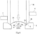
- the forming die 3 has a die part 3A that forms a curved end part Gp (refer to Fig. 6 ) heading inward on a lower end part of the leg part G, and a tapered part 3B that guides the leg part G to the die part.
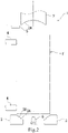
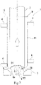
- FIG. 2 A reforming process using the tool 1 is explained with reference to Figs. 2 to 8 .
- a can body support part 4 and a stop part 5 are provided about the tool 1 composed of the pressing body 2 and the forming die 3.
- the pressing body 2 starts a stroke of moving in a direction approaching the forming die 3
- the pressing body 2 is positioned outside a receiving area F for the can body W.
- an air jetting part 6 is provided in a center part of the forming die 3.
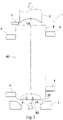
- the cylindrical barrel part W1 of the can body W is supported by the can body support part 4 provided about the receiving area F.
- the pressing body 2 continues moving in the direction of the arrow, and after the can body W is received, the pressing body 2 is inserted into the can body W.
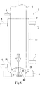
- the pressing body 2 is still further moved in the direction of the arrow, so that the can bottom part W2 pressed by the pressing body 2 moves toward the forming die 3.
- the annular leg part G is deformed by the die part 3A to form, as shown in Fig. 6 , the curved end part Gp heading inward on the lower end part thereof.
- the can body W that has been subjected to reforming is separated from the forming die 3 by jetting air from the air jetting part 6 while moving the pressing body 2 in a direction heading away from the forming die 3.
- the can body W receives air jetted from the air jetting part 6 to move to where an upper end part of the can body W abuts on the stop part 5.
- a rotation position S1 for example, approximately 30°
- the can body W is received in a rotation position S2 (for example, approximately 45°)
- the abutting surface 2A of the pressing body 2 is caused to abut on the inner surface of the dome part D in a rotation position S3 (for example, approximately 145°)
- the forming in the forming die 3 is started in a rotation position S4 (for example, approximately 163°)
- the reforming is ended in a rotation position S5 (for example, approximately 192°)
- the can body W is moved to the stop part 5 by air jetting in a rotation position S6 (for example, approximately 210°)
- the can body W is transferred in a rotation position S7 (for example, approximately 315°)
- the movement of the pressing body 2 is ended in a rotation position
- a delivering turret 11 delivers the can body W that has yet to be reformed (after primarily formed) to the forming turret 10 in the rotation position S2, and the receiving turret 12 receives the reformed can body W in the rotation position S7.
- Such a can bottom part W2 of the can body W reformed by the tool 1 is formed such that the curved end part Gp as curved inward is formed in the leg part G. More specifically, as shown in Fig. 10 , the leg part G of the can bottom part W2 has an outer leg part G1, a grounding end part G2, an inner end part G3, an inclined rising part G4, and an inner leg part G5.
- the curved end part Gp is formed of the grounding end part G2, the inner end part G3, and the inclined rising part G4.
- the inside of the curved end part Gp is connected to the periphery of the dome part D at the inner leg part G5, via the inclined rising part G4, from the inner end part G3, and is formed such that the inner leg part G5 has a greater inner diameter than the inner end part G3.
- t1 to t4 indicate the plate thickness of each part.
- the forming by abutting a roller or the like is eliminated, thus suppressing the defect of black discoloration in an associated formed portion.
- metal of the leg part G is not accumulated in the tool 1, thus enhancing the ease of maintenance of the forming device.
- the described embodiment exhibits an example in which the pressing body 2 is moved with respect to the forming die 3, the forming die 3 may contrariwise be moved with respect to the pressing body 2.
Landscapes
- Engineering & Computer Science (AREA)
- Mechanical Engineering (AREA)
- Shaping Metal By Deep-Drawing, Or The Like (AREA)
- Containers Having Bodies Formed In One Piece (AREA)
Applications Claiming Priority (2)
| Application Number | Priority Date | Filing Date | Title |
|---|---|---|---|
| JP2019204285 | 2019-11-11 | ||
| PCT/JP2020/030889 WO2021095309A1 (ja) | 2019-11-11 | 2020-08-14 | 缶体の成形装置 |
Publications (2)
| Publication Number | Publication Date |
|---|---|
| EP4059627A1 true EP4059627A1 (de) | 2022-09-21 |
| EP4059627A4 EP4059627A4 (de) | 2023-11-29 |
Family
ID=75912605
Family Applications (1)
| Application Number | Title | Priority Date | Filing Date |
|---|---|---|---|
| EP20886632.7A Pending EP4059627A4 (de) | 2019-11-11 | 2020-08-14 | Hohlkörperformvorrichtung |
Country Status (6)
| Country | Link |
|---|---|
| US (1) | US12233446B2 (de) |
| EP (1) | EP4059627A4 (de) |
| JP (1) | JP7521537B2 (de) |
| CN (1) | CN114502298B (de) |
| TW (1) | TWI757896B (de) |
| WO (1) | WO2021095309A1 (de) |
Families Citing this family (1)
| Publication number | Priority date | Publication date | Assignee | Title |
|---|---|---|---|---|
| JP7527905B2 (ja) * | 2020-09-10 | 2024-08-05 | 東洋製罐グループホールディングス株式会社 | 缶体の製造方法 |
Family Cites Families (14)
| Publication number | Priority date | Publication date | Assignee | Title |
|---|---|---|---|---|
| US3771345A (en) | 1972-06-08 | 1973-11-13 | Standun | End forming station for metallic can body formers and the like |
| DE2625170C2 (de) | 1976-06-04 | 1985-01-31 | Schmalbach-Lubeca Gmbh, 3300 Braunschweig | Verfahren und Vorrichtung zur Herstellung eines einendig geschlossenen Behälters aus Blech |
| JPS5925318U (ja) * | 1982-08-11 | 1984-02-16 | 日本軽金属株式会社 | 圧力容器の底部成形装置 |
| JPH09285832A (ja) | 1996-04-23 | 1997-11-04 | Kishimoto Akira | シームレス缶及びその成形法 |
| JP3916817B2 (ja) * | 1999-11-12 | 2007-05-23 | ユニバーサル製缶株式会社 | 缶 |
| US20040035871A1 (en) | 2002-08-20 | 2004-02-26 | Thomas Chupak | Aluminum aerosol can and aluminum bottle and method of manufacture |
| US10525519B2 (en) * | 2009-10-21 | 2020-01-07 | Stolle Machinery Company, Llc | Container, and selectively formed cup, tooling and associated method for providing same |
| JP2013103246A (ja) * | 2011-11-14 | 2013-05-30 | Daiwa Can Co Ltd | 樹脂被覆金属シームレス缶の製造装置 |
| WO2013118728A1 (ja) * | 2012-02-09 | 2013-08-15 | ユニバーサル製缶株式会社 | 缶製造装置 |
| JP6448217B2 (ja) | 2014-05-08 | 2019-01-09 | ユニバーサル製缶株式会社 | 缶 |
| CN106270266B (zh) | 2016-08-30 | 2018-01-23 | 广东韩江轻工机械有限公司 | 两片罐罐身生产工艺 |
| WO2018079434A1 (ja) * | 2016-10-25 | 2018-05-03 | 東洋製罐株式会社 | アルミニウム缶 |
| JP2018103227A (ja) | 2016-12-27 | 2018-07-05 | ユニバーサル製缶株式会社 | ボトムリフォーム機構、トップ支持部材、及び缶の製造方法 |
| EP4707190A2 (de) | 2019-01-30 | 2026-03-11 | Toyo Seikan Group Holdings, Ltd. | Nahtloser dosenkörper und verfahren zur herstellung eines nahtlosen dosenkörpers |
-
2020
- 2020-08-14 JP JP2021555905A patent/JP7521537B2/ja active Active
- 2020-08-14 US US17/774,286 patent/US12233446B2/en active Active
- 2020-08-14 EP EP20886632.7A patent/EP4059627A4/de active Pending
- 2020-08-14 CN CN202080069609.8A patent/CN114502298B/zh active Active
- 2020-08-14 WO PCT/JP2020/030889 patent/WO2021095309A1/ja not_active Ceased
- 2020-09-29 TW TW109133846A patent/TWI757896B/zh active
Also Published As
| Publication number | Publication date |
|---|---|
| EP4059627A4 (de) | 2023-11-29 |
| US20220388051A1 (en) | 2022-12-08 |
| CN114502298A (zh) | 2022-05-13 |
| TWI757896B (zh) | 2022-03-11 |
| US12233446B2 (en) | 2025-02-25 |
| JP7521537B2 (ja) | 2024-07-24 |
| JPWO2021095309A1 (de) | 2021-05-20 |
| WO2021095309A1 (ja) | 2021-05-20 |
| CN114502298B (zh) | 2024-08-23 |
| TW202120215A (zh) | 2021-06-01 |
Similar Documents
| Publication | Publication Date | Title |
|---|---|---|
| KR100264680B1 (ko) | 금속 컨테이너 본체를 형성하는 방법 | |
| EP0059196B1 (de) | Behälter | |
| US4685322A (en) | Method of forming a drawn and redrawn container body | |
| US4414836A (en) | Method of and apparatus for deep drawing metal containers | |
| JP6058002B2 (ja) | 缶製造方法および缶製造装置 | |
| JPH0150493B2 (de) | ||
| US8757953B2 (en) | Double seaming chuck-knockout | |
| EP4059627A1 (de) | Hohlkörperformvorrichtung | |
| US6666933B2 (en) | Can end, and method of manufacture therefor | |
| EP1337356A2 (de) | Aerosoldosenenden | |
| US3221403A (en) | Apparatus and method for producing closures in battery containers | |
| US5918499A (en) | Rivet formation | |
| EP0975449B1 (de) | Behälterdeckel herstellung | |
| JP2000197938A (ja) | 缶の製造方法および製造装置 | |
| JP2022186750A (ja) | シームレス缶体及びシームレス缶体の製造方法 | |
| JP2025007847A (ja) | 缶支持部材、シームレス缶の製造方法及び製造装置 | |
| JPH0852525A (ja) | Di缶体の成形方法 | |
| JPH0796137B2 (ja) | シームレス金属缶の製造方法 | |
| JPH0747183B2 (ja) | 金属缶の再成形方法 | |
| JPH11180429A (ja) | 缶及びその製造方法並びに製造装置 | |
| CA2746203A1 (en) | Double seaming chuck-knockout | |
| JP2018134664A (ja) | 缶の巻締め方法 | |
| NO160974B (no) | Fremgangsmaate ved utforming av hals paa beholdere. |
Legal Events
| Date | Code | Title | Description |
|---|---|---|---|
| STAA | Information on the status of an ep patent application or granted ep patent |
Free format text: STATUS: THE INTERNATIONAL PUBLICATION HAS BEEN MADE |
|
| PUAI | Public reference made under article 153(3) epc to a published international application that has entered the european phase |
Free format text: ORIGINAL CODE: 0009012 |
|
| STAA | Information on the status of an ep patent application or granted ep patent |
Free format text: STATUS: REQUEST FOR EXAMINATION WAS MADE |
|
| 17P | Request for examination filed |
Effective date: 20220607 |
|
| AK | Designated contracting states |
Kind code of ref document: A1 Designated state(s): AL AT BE BG CH CY CZ DE DK EE ES FI FR GB GR HR HU IE IS IT LI LT LU LV MC MK MT NL NO PL PT RO RS SE SI SK SM TR |
|
| DAV | Request for validation of the european patent (deleted) | ||
| DAX | Request for extension of the european patent (deleted) | ||
| A4 | Supplementary search report drawn up and despatched |
Effective date: 20231102 |
|
| RIC1 | Information provided on ipc code assigned before grant |
Ipc: B21D 22/30 20060101ALI20231026BHEP Ipc: B21D 51/26 20060101ALI20231026BHEP Ipc: B21D 22/28 20060101ALI20231026BHEP Ipc: B21D 22/26 20060101ALI20231026BHEP Ipc: B21D 22/02 20060101AFI20231026BHEP |