EP4059627A1 - Hollow body molding device - Google Patents
Hollow body molding device Download PDFInfo
- Publication number
- EP4059627A1 EP4059627A1 EP20886632.7A EP20886632A EP4059627A1 EP 4059627 A1 EP4059627 A1 EP 4059627A1 EP 20886632 A EP20886632 A EP 20886632A EP 4059627 A1 EP4059627 A1 EP 4059627A1
- Authority
- EP
- European Patent Office
- Prior art keywords
- forming
- forming device
- dome
- leg
- pressing body
- Prior art date
- Legal status (The legal status is an assumption and is not a legal conclusion. Google has not performed a legal analysis and makes no representation as to the accuracy of the status listed.)
- Pending
Links
- 238000000465 moulding Methods 0.000 title 1
- 238000002407 reforming Methods 0.000 abstract description 14
- 238000002845 discoloration Methods 0.000 abstract description 5
- 230000007547 defect Effects 0.000 abstract description 4
- 238000000034 method Methods 0.000 description 16
- 238000012423 maintenance Methods 0.000 description 4
- 230000000630 rising effect Effects 0.000 description 4
- 230000007246 mechanism Effects 0.000 description 2
- 239000007769 metal material Substances 0.000 description 2
- 229910000838 Al alloy Inorganic materials 0.000 description 1
- 238000009825 accumulation Methods 0.000 description 1
- 230000000694 effects Effects 0.000 description 1
- 230000002708 enhancing effect Effects 0.000 description 1
- 238000010409 ironing Methods 0.000 description 1
- 239000000463 material Substances 0.000 description 1
- 229910052751 metal Inorganic materials 0.000 description 1
- 239000002184 metal Substances 0.000 description 1
- 230000002093 peripheral effect Effects 0.000 description 1
- 230000001954 sterilising effect Effects 0.000 description 1
- 238000004659 sterilization and disinfection Methods 0.000 description 1
Images


Classifications
-
- B—PERFORMING OPERATIONS; TRANSPORTING
- B21—MECHANICAL METAL-WORKING WITHOUT ESSENTIALLY REMOVING MATERIAL; PUNCHING METAL
- B21D—WORKING OR PROCESSING OF SHEET METAL OR METAL TUBES, RODS OR PROFILES WITHOUT ESSENTIALLY REMOVING MATERIAL; PUNCHING METAL
- B21D51/00—Making hollow objects
- B21D51/16—Making hollow objects characterised by the use of the objects
- B21D51/18—Making hollow objects characterised by the use of the objects vessels, e.g. tubs, vats, tanks, sinks, or the like
-
- B—PERFORMING OPERATIONS; TRANSPORTING
- B21—MECHANICAL METAL-WORKING WITHOUT ESSENTIALLY REMOVING MATERIAL; PUNCHING METAL
- B21D—WORKING OR PROCESSING OF SHEET METAL OR METAL TUBES, RODS OR PROFILES WITHOUT ESSENTIALLY REMOVING MATERIAL; PUNCHING METAL
- B21D51/00—Making hollow objects
- B21D51/16—Making hollow objects characterised by the use of the objects
- B21D51/26—Making hollow objects characterised by the use of the objects cans or tins; Closing same in a permanent manner
- B21D51/2669—Transforming the shape of formed can bodies; Forming can bodies from flattened tubular blanks; Flattening can bodies
-
- B—PERFORMING OPERATIONS; TRANSPORTING
- B21—MECHANICAL METAL-WORKING WITHOUT ESSENTIALLY REMOVING MATERIAL; PUNCHING METAL
- B21D—WORKING OR PROCESSING OF SHEET METAL OR METAL TUBES, RODS OR PROFILES WITHOUT ESSENTIALLY REMOVING MATERIAL; PUNCHING METAL
- B21D22/00—Shaping without cutting, by stamping, spinning, or deep-drawing
- B21D22/20—Deep-drawing
- B21D22/26—Deep-drawing for making peculiarly, e.g. irregularly, shaped articles
-
- B—PERFORMING OPERATIONS; TRANSPORTING
- B21—MECHANICAL METAL-WORKING WITHOUT ESSENTIALLY REMOVING MATERIAL; PUNCHING METAL
- B21D—WORKING OR PROCESSING OF SHEET METAL OR METAL TUBES, RODS OR PROFILES WITHOUT ESSENTIALLY REMOVING MATERIAL; PUNCHING METAL
- B21D22/00—Shaping without cutting, by stamping, spinning, or deep-drawing
- B21D22/20—Deep-drawing
- B21D22/28—Deep-drawing of cylindrical articles using consecutive dies
-
- B—PERFORMING OPERATIONS; TRANSPORTING
- B21—MECHANICAL METAL-WORKING WITHOUT ESSENTIALLY REMOVING MATERIAL; PUNCHING METAL
- B21D—WORKING OR PROCESSING OF SHEET METAL OR METAL TUBES, RODS OR PROFILES WITHOUT ESSENTIALLY REMOVING MATERIAL; PUNCHING METAL
- B21D22/00—Shaping without cutting, by stamping, spinning, or deep-drawing
- B21D22/20—Deep-drawing
- B21D22/30—Deep-drawing to finish articles formed by deep-drawing
-
- B—PERFORMING OPERATIONS; TRANSPORTING
- B21—MECHANICAL METAL-WORKING WITHOUT ESSENTIALLY REMOVING MATERIAL; PUNCHING METAL
- B21D—WORKING OR PROCESSING OF SHEET METAL OR METAL TUBES, RODS OR PROFILES WITHOUT ESSENTIALLY REMOVING MATERIAL; PUNCHING METAL
- B21D37/00—Tools as parts of machines covered by this subclass
- B21D37/10—Die sets; Pillar guides
-
- B—PERFORMING OPERATIONS; TRANSPORTING
- B21—MECHANICAL METAL-WORKING WITHOUT ESSENTIALLY REMOVING MATERIAL; PUNCHING METAL
- B21D—WORKING OR PROCESSING OF SHEET METAL OR METAL TUBES, RODS OR PROFILES WITHOUT ESSENTIALLY REMOVING MATERIAL; PUNCHING METAL
- B21D45/00—Ejecting or stripping-off devices arranged in machines or tools dealt with in this subclass
- B21D45/02—Ejecting devices
- B21D45/04—Ejecting devices interrelated with motion of tool
-
- B—PERFORMING OPERATIONS; TRANSPORTING
- B21—MECHANICAL METAL-WORKING WITHOUT ESSENTIALLY REMOVING MATERIAL; PUNCHING METAL
- B21D—WORKING OR PROCESSING OF SHEET METAL OR METAL TUBES, RODS OR PROFILES WITHOUT ESSENTIALLY REMOVING MATERIAL; PUNCHING METAL
- B21D51/00—Making hollow objects
- B21D51/16—Making hollow objects characterised by the use of the objects
- B21D51/26—Making hollow objects characterised by the use of the objects cans or tins; Closing same in a permanent manner
Definitions
- the present invention relates to a forming device for reforming a can bottom part (bottom) of a can body.
- a can body called a seamless can (alternatively, two-piece can) has a can barrel part, etc., formed by a drawing and ironing process.
- a can barrel part etc., formed by a drawing and ironing process.
- decrease in the thickness of the can barrel part has been pursued to save resources and reduce weight.
- a concave dome part is formed in a can bottom part, and an annular leg part is formed on a periphery thereof.
- a variety of ingenious shapes are designed for a grounding part of the leg part to prevent buckling and the like.
- a forming process for the can bottom part includes, as a first stage process, forming a center part thereof into a concave shape to form the dome part and the leg part, and as a second stage process, reforming the leg part.
- a conventionally-known device for such reforming is provided with a frame serving as a base, a rotation shaft that is supported by the frame and rotationally driven, a turret that is supported by the rotation shaft and has pockets on an outer periphery thereof to hold can bodies, and reform mechanisms that are supported by the rotation shaft and provided to respectively correspond to the pockets, and the reform mechanisms are each provided with a top spindle and a bottom spindle (refer to PTL 1 below).
- a problem to be addressed by the present invention is to suppress the defect of black discoloration in an associated formed portion in reforming a can bottom part, enhance the ease of maintenance of a forming device, and so forth.
- the present invention is provided with the configuration below.
- a can body forming device for forming a can body in which a cylindrical barrel part and a can bottom part are integrally formed, includes a tool used for the can body having a concave dome part in a center of the can bottom part and having an annular leg part on a periphery of the dome part to reform a shape of the leg part, and the tool includes a pressing body that is inserted into the can body, and that abuts on an inner surface of the dome part, and a forming die that forms a curved end part heading inward on a lower end part of the leg part.
- the present invention having these features suppresses the defect of black discoloration in an associated formed portion in reforming the leg part of the can bottom part, and enhances the ease of maintenance of the forming device.
- a can body forming device includes a tool 1 for reforming a leg part G of a can bottom part W2 of a can body (for example, two-piece can) W in which a cylindrical barrel part W1 and the can bottom part W2 are integrally formed.
- the tool 1 subjects the can body (a primarily-formed can body) having a concave dome part D in a center of the can bottom part W2, and an annular leg part G on the periphery of the dome part D to reforming.
- the tool 1 includes a pressing body 2 and a forming die 3.
- the pressing body 2 is inserted into the can body W, and has an abutting surface 2A that abuts on an inner surface of the dome part D.
- the forming die 3 has a die part 3A that forms a curved end part Gp (refer to Fig. 6 ) heading inward on a lower end part of the leg part G, and a tapered part 3B that guides the leg part G to the die part.
- FIG. 2 A reforming process using the tool 1 is explained with reference to Figs. 2 to 8 .
- a can body support part 4 and a stop part 5 are provided about the tool 1 composed of the pressing body 2 and the forming die 3.
- the pressing body 2 starts a stroke of moving in a direction approaching the forming die 3
- the pressing body 2 is positioned outside a receiving area F for the can body W.
- an air jetting part 6 is provided in a center part of the forming die 3.
- the cylindrical barrel part W1 of the can body W is supported by the can body support part 4 provided about the receiving area F.
- the pressing body 2 continues moving in the direction of the arrow, and after the can body W is received, the pressing body 2 is inserted into the can body W.
- the pressing body 2 is still further moved in the direction of the arrow, so that the can bottom part W2 pressed by the pressing body 2 moves toward the forming die 3.
- the annular leg part G is deformed by the die part 3A to form, as shown in Fig. 6 , the curved end part Gp heading inward on the lower end part thereof.
- the can body W that has been subjected to reforming is separated from the forming die 3 by jetting air from the air jetting part 6 while moving the pressing body 2 in a direction heading away from the forming die 3.
- the can body W receives air jetted from the air jetting part 6 to move to where an upper end part of the can body W abuts on the stop part 5.
- a rotation position S1 for example, approximately 30°
- the can body W is received in a rotation position S2 (for example, approximately 45°)
- the abutting surface 2A of the pressing body 2 is caused to abut on the inner surface of the dome part D in a rotation position S3 (for example, approximately 145°)
- the forming in the forming die 3 is started in a rotation position S4 (for example, approximately 163°)
- the reforming is ended in a rotation position S5 (for example, approximately 192°)
- the can body W is moved to the stop part 5 by air jetting in a rotation position S6 (for example, approximately 210°)
- the can body W is transferred in a rotation position S7 (for example, approximately 315°)
- the movement of the pressing body 2 is ended in a rotation position
- a delivering turret 11 delivers the can body W that has yet to be reformed (after primarily formed) to the forming turret 10 in the rotation position S2, and the receiving turret 12 receives the reformed can body W in the rotation position S7.
- Such a can bottom part W2 of the can body W reformed by the tool 1 is formed such that the curved end part Gp as curved inward is formed in the leg part G. More specifically, as shown in Fig. 10 , the leg part G of the can bottom part W2 has an outer leg part G1, a grounding end part G2, an inner end part G3, an inclined rising part G4, and an inner leg part G5.
- the curved end part Gp is formed of the grounding end part G2, the inner end part G3, and the inclined rising part G4.
- the inside of the curved end part Gp is connected to the periphery of the dome part D at the inner leg part G5, via the inclined rising part G4, from the inner end part G3, and is formed such that the inner leg part G5 has a greater inner diameter than the inner end part G3.
- t1 to t4 indicate the plate thickness of each part.
- the forming by abutting a roller or the like is eliminated, thus suppressing the defect of black discoloration in an associated formed portion.
- metal of the leg part G is not accumulated in the tool 1, thus enhancing the ease of maintenance of the forming device.
- the described embodiment exhibits an example in which the pressing body 2 is moved with respect to the forming die 3, the forming die 3 may contrariwise be moved with respect to the pressing body 2.
Landscapes
- Engineering & Computer Science (AREA)
- Mechanical Engineering (AREA)
- Shaping Metal By Deep-Drawing, Or The Like (AREA)
- Containers Having Bodies Formed In One Piece (AREA)
Abstract
Description
- The present invention relates to a forming device for reforming a can bottom part (bottom) of a can body.
- A can body called a seamless can (alternatively, two-piece can) has a can barrel part, etc., formed by a drawing and ironing process. For such a can body, decrease in the thickness of the can barrel part has been pursued to save resources and reduce weight. To ensure pressure-resistant strength, a concave dome part is formed in a can bottom part, and an annular leg part is formed on a periphery thereof. In addition, a variety of ingenious shapes are designed for a grounding part of the leg part to prevent buckling and the like.
- A forming process for the can bottom part includes, as a first stage process, forming a center part thereof into a concave shape to form the dome part and the leg part, and as a second stage process, reforming the leg part. A conventionally-known device for such reforming is provided with a frame serving as a base, a rotation shaft that is supported by the frame and rotationally driven, a turret that is supported by the rotation shaft and has pockets on an outer periphery thereof to hold can bodies, and reform mechanisms that are supported by the rotation shaft and provided to respectively correspond to the pockets, and the reform mechanisms are each provided with a top spindle and a bottom spindle (refer to
PTL 1 below). - [PTL 1]
Japanese Patent Application Publication No. 2018-103227 - In the process of reforming the leg part of the can bottom part according to the conventional art mentioned above, an inner peripheral wall of the annular leg part is pressed using a roller or the like. This harms the oxide film of an aluminum alloy that is a can material, whereby an associated pressed portion is prone to undesired black discoloration at the time of heat sterilization or the like after the contents are filled, and also a complicated maintenance of the forming device occurs due to adhesion of metal material of the can bottom to the roller or the like.
- The present invention has been proposed to address such circumstances. That is to say, a problem to be addressed by the present invention is to suppress the defect of black discoloration in an associated formed portion in reforming a can bottom part, enhance the ease of maintenance of a forming device, and so forth.
- To solve the problem, the present invention is provided with the configuration below.
- A can body forming device for forming a can body, in which a cylindrical barrel part and a can bottom part are integrally formed, includes a tool used for the can body having a concave dome part in a center of the can bottom part and having an annular leg part on a periphery of the dome part to reform a shape of the leg part, and the tool includes a pressing body that is inserted into the can body, and that abuts on an inner surface of the dome part, and a forming die that forms a curved end part heading inward on a lower end part of the leg part.
- The present invention having these features suppresses the defect of black discoloration in an associated formed portion in reforming the leg part of the can bottom part, and enhances the ease of maintenance of the forming device.
-
- [
Fig. 1 ]
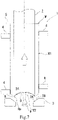
Fig. 1 is a cross-sectional view of a tool in a can body forming device according to the present invention. - [
Fig. 2 ]
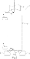
Fig. 2 illustrates one forming process by the can body forming device (starting stroke of a pressing body). - [
Fig. 3 ]
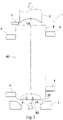
Fig. 3 illustrates one forming process by the can body forming device (receiving a can body). - [
Fig. 4 ]
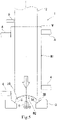
Fig. 4 illustrates one forming process by the can body forming device (bringing the pressing body and a can bottom part into contact with each other). - [
Fig. 5 ]
Fig. 5 illustrates one forming process by the can body forming device (starting forming). - [
Fig. 6 ]
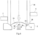
Fig. 6 illustrates one forming process by the can body forming device (ending forming). - [
Fig. 7 ]
Fig. 7 illustrates one forming process by the can body forming device (jetting air). - [
Fig. 8 ]
Fig. 8 illustrates one forming process by the can body forming device (transferring the can body). - [
Fig. 9 ]
Fig. 9 illustrates process timings in a forming turret. - [
Fig. 10 ]
Fig. 10 is a cross-sectional view of the can bottom part of the reformed can body. - Hereinafter, embodiments of the present invention will be explained with reference to the drawings. In the following explanation, the same sign in different figures denotes a portion of the same function, and redundant explanation in each of the figures is omitted as appropriate.
- As shown in
Fig. 1 , a can body forming device according to the present invention includes atool 1 for reforming a leg part G of a can bottom part W2 of a can body (for example, two-piece can) W in which a cylindrical barrel part W1 and the can bottom part W2 are integrally formed. Thetool 1 subjects the can body (a primarily-formed can body) having a concave dome part D in a center of the can bottom part W2, and an annular leg part G on the periphery of the dome part D to reforming. - The
tool 1 includes apressing body 2 and a forming die 3. Thepressing body 2 is inserted into the can body W, and has anabutting surface 2A that abuts on an inner surface of the dome part D. The forming die 3 has adie part 3A that forms a curved end part Gp (refer toFig. 6 ) heading inward on a lower end part of the leg part G, and atapered part 3B that guides the leg part G to the die part. - A reforming process using the
tool 1 is explained with reference toFigs. 2 to 8 . As shown inFig. 2 , a can body supportpart 4 and astop part 5 are provided about thetool 1 composed of thepressing body 2 and the formingdie 3. When thepressing body 2 starts a stroke of moving in a direction approaching the formingdie 3, thepressing body 2 is positioned outside a receiving area F for the can body W. In addition, anair jetting part 6 is provided in a center part of the formingdie 3. - As shown in
Fig. 3 , once the can body W is received in the receiving area F, the cylindrical barrel part W1 of the can body W is supported by the canbody support part 4 provided about the receiving area F. In the meantime, thepressing body 2 continues moving in the direction of the arrow, and after the can body W is received, thepressing body 2 is inserted into the can body W. - As shown in
Fig. 4 , when thepressing body 2 is further moved in the direction of the arrow to cause theabutting surface 2A of thepressing body 2 to abut on the inner surface of the dome part D of the can bottom part W2, air is jetted from theair jetting part 6 toward the outside of the dome part D. This jet of air allows the dome part D of the can bottom part W2 to abut in a stable state on theabutting surface 2A of thepressing body 2. - Then, as shown in
Fig. 5 , thepressing body 2 is still further moved in the direction of the arrow, so that the can bottom part W2 pressed by thepressing body 2 moves toward the formingdie 3. Once the lower end part of the leg part G of the can bottom part W2 is thus pressed on along thetapered part 3B of the formingdie 3, the annular leg part G is deformed by thedie part 3A to form, as shown inFig. 6 , the curved end part Gp heading inward on the lower end part thereof. Thus the reforming ends. - Then, as shown in
Fig. 7 , the can body W that has been subjected to reforming is separated from the formingdie 3 by jetting air from theair jetting part 6 while moving thepressing body 2 in a direction heading away from the formingdie 3. At this time, with thestop part 5 provided outside the receiving area F in a can axis direction, the can body W receives air jetted from theair jetting part 6 to move to where an upper end part of the can body W abuts on thestop part 5. - Still thereafter, as shown in
Fig. 8 , thepressing body 2 is moved out of the receiving area F, the can body W is taken out of the receiving area F, and then the process goes for the next can body W. This configuration causes little frictional force between the can body W and the formingdie 3, unlike the conventional art of making a press using a roller or the like, thus eliminating the accumulation of metal material in the formingdie 3. - This series of processes is performed within the span of one rotation of a forming
turret 10 as shown inFig. 9 . In an example shown inFig. 9 , from the position of 0°, the movement of thepressing body 2 is started in a rotation position S1 (for example, approximately 30°), the can body W is received in a rotation position S2 (for example, approximately 45°), theabutting surface 2A of thepressing body 2 is caused to abut on the inner surface of the dome part D in a rotation position S3 (for example, approximately 145°), the forming in the formingdie 3 is started in a rotation position S4 (for example, approximately 163°), the reforming is ended in a rotation position S5 (for example, approximately 192°), the can body W is moved to thestop part 5 by air jetting in a rotation position S6 (for example, approximately 210°), the can body W is transferred in a rotation position S7 (for example, approximately 315°), and the movement of thepressing body 2 is ended in a rotation position S8 (for example, approximately 330°). - Provided adjacent to the forming
turret 10 are a deliveringturret 11 and a receivingturret 12 for the can body W. The deliveringturret 11 delivers the can body W that has yet to be reformed (after primarily formed) to the formingturret 10 in the rotation position S2, and the receivingturret 12 receives the reformed can body W in the rotation position S7. - Such a can bottom part W2 of the can body W reformed by the
tool 1 is formed such that the curved end part Gp as curved inward is formed in the leg part G. More specifically, as shown inFig. 10 , the leg part G of the can bottom part W2 has an outer leg part G1, a grounding end part G2, an inner end part G3, an inclined rising part G4, and an inner leg part G5. The curved end part Gp is formed of the grounding end part G2, the inner end part G3, and the inclined rising part G4. - In this regard, the inside of the curved end part Gp is connected to the periphery of the dome part D at the inner leg part G5, via the inclined rising part G4, from the inner end part G3, and is formed such that the inner leg part G5 has a greater inner diameter than the inner end part G3. In
Fig. 10 , t1 to t4 indicate the plate thickness of each part. - As explained above, in reforming the leg part G of the can bottom part W2 in accordance with the embodiment of the present invention, the forming by abutting a roller or the like is eliminated, thus suppressing the defect of black discoloration in an associated formed portion. In addition, metal of the leg part G is not accumulated in the
tool 1, thus enhancing the ease of maintenance of the forming device. Meanwhile, although the described embodiment exhibits an example in which thepressing body 2 is moved with respect to the formingdie 3, the formingdie 3 may contrariwise be moved with respect to thepressing body 2. -
- 1
- Tool
- 2
- Pressing body
- 3
- Forming die
- 4
- Can body support part
- 5
- Stop part
- 6
- Air jetting part
- 10
- Forming turret
- 2A
- Abutting surface
- 3A
- Die part
- 3B
- Tapered part
- W
- Can body
- W1
- Cylindrical barrel part
- W2
- Can bottom part
- D
- Dome part
- G
- Leg part
- G1
- Outer leg part
- G2
- Grounding end part
- G3
- Inner end part
- G4
- Inclined rising part
- G5
- Inner leg part
- Gp
- Curved end part, receiving area F
Claims (4)
- A can body forming device for forming a can body in which a cylindrical barrel part and a can bottom part are integrally formed, the can body forming device comprising:a tool used for the can body having a concave dome part in a center of the can bottom part and having an annular leg part formed on a periphery of the dome part to reform a shape of the leg part,wherein the tool includes: a pressing body that is inserted into the can body, and that abuts on an inner surface of the dome part; and a forming die that forms a curved end part heading inward on a lower end part of the leg part.
- The can body forming device according to claim 1,
wherein an air jetting part for causing the can bottom part to abut on an abutting surface of the pressing body is provided in a center part of the forming die. - The can body forming device according to claim 1 or 2, further comprising:a can body support part that supports a periphery of the cylindrical barrel part; anda stop part that receives an upper end of the can body when the can body that has the formed curved end part is separated from the pressing body.
- The can body forming device according to any one of claims 1-3, further comprising:
a forming turret including, about a rotation axis, multiple pairs each composed of the pressing body and the forming die.
Applications Claiming Priority (2)
| Application Number | Priority Date | Filing Date | Title |
|---|---|---|---|
| JP2019204285 | 2019-11-11 | ||
| PCT/JP2020/030889 WO2021095309A1 (en) | 2019-11-11 | 2020-08-14 | Hollow body molding device |
Publications (2)
| Publication Number | Publication Date |
|---|---|
| EP4059627A1 true EP4059627A1 (en) | 2022-09-21 |
| EP4059627A4 EP4059627A4 (en) | 2023-11-29 |
Family
ID=75912605
Family Applications (1)
| Application Number | Title | Priority Date | Filing Date |
|---|---|---|---|
| EP20886632.7A Pending EP4059627A4 (en) | 2019-11-11 | 2020-08-14 | Hollow body molding device |
Country Status (6)
| Country | Link |
|---|---|
| US (1) | US20220388051A1 (en) |
| EP (1) | EP4059627A4 (en) |
| JP (1) | JPWO2021095309A1 (en) |
| CN (1) | CN114502298A (en) |
| TW (1) | TWI757896B (en) |
| WO (1) | WO2021095309A1 (en) |
Families Citing this family (1)
| Publication number | Priority date | Publication date | Assignee | Title |
|---|---|---|---|---|
| JP2022046224A (en) * | 2020-09-10 | 2022-03-23 | 東洋製罐グループホールディングス株式会社 | Can body manufacturing method and can body manufacturing line |
Family Cites Families (13)
| Publication number | Priority date | Publication date | Assignee | Title |
|---|---|---|---|---|
| US3771345A (en) * | 1972-06-08 | 1973-11-13 | Standun | End forming station for metallic can body formers and the like |
| DE2625170C2 (en) * | 1976-06-04 | 1985-01-31 | Schmalbach-Lubeca Gmbh, 3300 Braunschweig | Method and device for the production of a container closed at one end from sheet metal |
| JPH09285832A (en) * | 1996-04-23 | 1997-11-04 | Kishimoto Akira | Seamless can and its forming method |
| JP3916817B2 (en) * | 1999-11-12 | 2007-05-23 | ユニバーサル製缶株式会社 | can |
| US20040035871A1 (en) * | 2002-08-20 | 2004-02-26 | Thomas Chupak | Aluminum aerosol can and aluminum bottle and method of manufacture |
| US10525519B2 (en) * | 2009-10-21 | 2020-01-07 | Stolle Machinery Company, Llc | Container, and selectively formed cup, tooling and associated method for providing same |
| JP2013103246A (en) * | 2011-11-14 | 2013-05-30 | Daiwa Can Co Ltd | Apparatus for manufacturing resin coated metallic seamless can |
| EP2813300B1 (en) * | 2012-02-09 | 2016-05-25 | Universal Can Corporation | Can production device |
| JP6448217B2 (en) * | 2014-05-08 | 2019-01-09 | ユニバーサル製缶株式会社 | can |
| CN106270266B (en) * | 2016-08-30 | 2018-01-23 | 广东韩江轻工机械有限公司 | Two-piece can body production technology |
| KR20190060845A (en) * | 2016-10-25 | 2019-06-03 | 토요 세이칸 가부시키가이샤 | aluminum can |
| JP2018103227A (en) * | 2016-12-27 | 2018-07-05 | ユニバーサル製缶株式会社 | Bottom reform mechanism, top support member, and can manufacturing method |
| CN113507993A (en) * | 2019-01-30 | 2021-10-15 | 东洋制罐集团控股株式会社 | Seamless can body and method for manufacturing seamless can body |
-
2020
- 2020-08-14 EP EP20886632.7A patent/EP4059627A4/en active Pending
- 2020-08-14 JP JP2021555905A patent/JPWO2021095309A1/ja active Pending
- 2020-08-14 WO PCT/JP2020/030889 patent/WO2021095309A1/en unknown
- 2020-08-14 US US17/774,286 patent/US20220388051A1/en active Pending
- 2020-08-14 CN CN202080069609.8A patent/CN114502298A/en active Pending
- 2020-09-29 TW TW109133846A patent/TWI757896B/en active
Also Published As
| Publication number | Publication date |
|---|---|
| TWI757896B (en) | 2022-03-11 |
| US20220388051A1 (en) | 2022-12-08 |
| TW202120215A (en) | 2021-06-01 |
| CN114502298A (en) | 2022-05-13 |
| WO2021095309A1 (en) | 2021-05-20 |
| JPWO2021095309A1 (en) | 2021-05-20 |
| EP4059627A4 (en) | 2023-11-29 |
Similar Documents
| Publication | Publication Date | Title |
|---|---|---|
| KR100264680B1 (en) | Method of forming a metallic container body | |
| EP0059196B1 (en) | Containers | |
| US4685322A (en) | Method of forming a drawn and redrawn container body | |
| US4414836A (en) | Method of and apparatus for deep drawing metal containers | |
| JP6058002B2 (en) | Can manufacturing method and can manufacturing apparatus | |
| US6038910A (en) | Method and apparatus for forming tapered metal container bodies | |
| JPH0150493B2 (en) | ||
| WO1998034743A1 (en) | Can ends | |
| EP4059627A1 (en) | Hollow body molding device | |
| US8757953B2 (en) | Double seaming chuck-knockout | |
| EP1337356A2 (en) | Aerosol can ends | |
| US20020046786A1 (en) | Can end, and method of manufacture therefor | |
| JP4112137B2 (en) | Can and manufacturing method thereof | |
| US3221403A (en) | Apparatus and method for producing closures in battery containers | |
| US5918499A (en) | Rivet formation | |
| EP0975449B1 (en) | Container end manufacture | |
| JP3546733B2 (en) | Can manufacturing method and manufacturing apparatus | |
| JP2019010662A (en) | Can bottom molding device | |
| JP2022186750A (en) | Seamless can body and method for manufacturing the same | |
| JPH0852525A (en) | Forming method of di can | |
| JPH0796137B2 (en) | Seamless metal can manufacturing method | |
| JPH0747183B2 (en) | Reforming method for metal can | |
| JPH10216873A (en) | Method for necking can | |
| JPH11180429A (en) | Can, manufacture thereof, and apparatus for manufacture of can | |
| CA2746203A1 (en) | Double seaming chuck-knockout |
Legal Events
| Date | Code | Title | Description |
|---|---|---|---|
| STAA | Information on the status of an ep patent application or granted ep patent |
Free format text: STATUS: THE INTERNATIONAL PUBLICATION HAS BEEN MADE |
|
| PUAI | Public reference made under article 153(3) epc to a published international application that has entered the european phase |
Free format text: ORIGINAL CODE: 0009012 |
|
| STAA | Information on the status of an ep patent application or granted ep patent |
Free format text: STATUS: REQUEST FOR EXAMINATION WAS MADE |
|
| 17P | Request for examination filed |
Effective date: 20220607 |
|
| AK | Designated contracting states |
Kind code of ref document: A1 Designated state(s): AL AT BE BG CH CY CZ DE DK EE ES FI FR GB GR HR HU IE IS IT LI LT LU LV MC MK MT NL NO PL PT RO RS SE SI SK SM TR |
|
| DAV | Request for validation of the european patent (deleted) | ||
| DAX | Request for extension of the european patent (deleted) | ||
| A4 | Supplementary search report drawn up and despatched |
Effective date: 20231102 |
|
| RIC1 | Information provided on ipc code assigned before grant |
Ipc: B21D 22/30 20060101ALI20231026BHEP Ipc: B21D 51/26 20060101ALI20231026BHEP Ipc: B21D 22/28 20060101ALI20231026BHEP Ipc: B21D 22/26 20060101ALI20231026BHEP Ipc: B21D 22/02 20060101AFI20231026BHEP |