EP4059403B1 - Verfahren und vorrichtung zur steuerung einer reinigungsvorrichtung - Google Patents
Verfahren und vorrichtung zur steuerung einer reinigungsvorrichtung Download PDFInfo
- Publication number
- EP4059403B1 EP4059403B1 EP21867901.7A EP21867901A EP4059403B1 EP 4059403 B1 EP4059403 B1 EP 4059403B1 EP 21867901 A EP21867901 A EP 21867901A EP 4059403 B1 EP4059403 B1 EP 4059403B1
- Authority
- EP
- European Patent Office
- Prior art keywords
- angle
- cleaning equipment
- turn
- running
- controlling
- Prior art date
- Legal status (The legal status is an assumption and is not a legal conclusion. Google has not performed a legal analysis and makes no representation as to the accuracy of the status listed.)
- Active
Links
Images


Classifications
-
- G—PHYSICS
- G05—CONTROLLING; REGULATING
- G05D—SYSTEMS FOR CONTROLLING OR REGULATING NON-ELECTRIC VARIABLES
- G05D1/00—Control of position, course, altitude or attitude of land, water, air or space vehicles, e.g. using automatic pilots
- G05D1/02—Control of position or course in two dimensions
- G05D1/021—Control of position or course in two dimensions specially adapted to land vehicles
- G05D1/0212—Control of position or course in two dimensions specially adapted to land vehicles with means for defining a desired trajectory
- G05D1/0214—Control of position or course in two dimensions specially adapted to land vehicles with means for defining a desired trajectory in accordance with safety or protection criteria, e.g. avoiding hazardous areas
-
- G—PHYSICS
- G05—CONTROLLING; REGULATING
- G05D—SYSTEMS FOR CONTROLLING OR REGULATING NON-ELECTRIC VARIABLES
- G05D1/00—Control of position, course, altitude or attitude of land, water, air or space vehicles, e.g. using automatic pilots
- G05D1/02—Control of position or course in two dimensions
- G05D1/021—Control of position or course in two dimensions specially adapted to land vehicles
- G05D1/0231—Control of position or course in two dimensions specially adapted to land vehicles using optical position detecting means
- G05D1/0242—Control of position or course in two dimensions specially adapted to land vehicles using optical position detecting means using non-visible light signals, e.g. IR or UV signals
-
- E—FIXED CONSTRUCTIONS
- E04—BUILDING
- E04H—BUILDINGS OR LIKE STRUCTURES FOR PARTICULAR PURPOSES; SWIMMING OR SPLASH BATHS OR POOLS; MASTS; FENCING; TENTS OR CANOPIES, IN GENERAL
- E04H4/00—Swimming or splash baths or pools
- E04H4/14—Parts, details or accessories not otherwise provided for
- E04H4/16—Parts, details or accessories not otherwise provided for specially adapted for cleaning
- E04H4/1654—Self-propelled cleaners
-
- G—PHYSICS
- G05—CONTROLLING; REGULATING
- G05D—SYSTEMS FOR CONTROLLING OR REGULATING NON-ELECTRIC VARIABLES
- G05D1/00—Control of position, course, altitude or attitude of land, water, air or space vehicles, e.g. using automatic pilots
- G05D1/02—Control of position or course in two dimensions
- G05D1/021—Control of position or course in two dimensions specially adapted to land vehicles
- G05D1/0212—Control of position or course in two dimensions specially adapted to land vehicles with means for defining a desired trajectory
- G05D1/0219—Control of position or course in two dimensions specially adapted to land vehicles with means for defining a desired trajectory ensuring the processing of the whole working surface
-
- G—PHYSICS
- G05—CONTROLLING; REGULATING
- G05D—SYSTEMS FOR CONTROLLING OR REGULATING NON-ELECTRIC VARIABLES
- G05D1/00—Control of position, course, altitude or attitude of land, water, air or space vehicles, e.g. using automatic pilots
- G05D1/02—Control of position or course in two dimensions
- G05D1/021—Control of position or course in two dimensions specially adapted to land vehicles
- G05D1/0212—Control of position or course in two dimensions specially adapted to land vehicles with means for defining a desired trajectory
- G05D1/0223—Control of position or course in two dimensions specially adapted to land vehicles with means for defining a desired trajectory involving speed control of the vehicle
-
- G—PHYSICS
- G05—CONTROLLING; REGULATING
- G05D—SYSTEMS FOR CONTROLLING OR REGULATING NON-ELECTRIC VARIABLES
- G05D1/00—Control of position, course, altitude or attitude of land, water, air or space vehicles, e.g. using automatic pilots
- G05D1/02—Control of position or course in two dimensions
- G05D1/021—Control of position or course in two dimensions specially adapted to land vehicles
- G05D1/0268—Control of position or course in two dimensions specially adapted to land vehicles using internal positioning means
- G05D1/027—Control of position or course in two dimensions specially adapted to land vehicles using internal positioning means comprising intertial navigation means, e.g. azimuth detector
-
- G—PHYSICS
- G05—CONTROLLING; REGULATING
- G05D—SYSTEMS FOR CONTROLLING OR REGULATING NON-ELECTRIC VARIABLES
- G05D1/00—Control of position, course, altitude or attitude of land, water, air or space vehicles, e.g. using automatic pilots
- G05D1/60—Intended control result
- G05D1/648—Performing a task within a working area or space, e.g. cleaning
- G05D1/6484—Performing a task within a working area or space, e.g. cleaning by taking into account parameters or characteristics of the working area or space, e.g. size or shape
-
- G—PHYSICS
- G05—CONTROLLING; REGULATING
- G05D—SYSTEMS FOR CONTROLLING OR REGULATING NON-ELECTRIC VARIABLES
- G05D2111/00—Details of signals used for control of position, course, altitude or attitude of land, water, air or space vehicles
- G05D2111/10—Optical signals
- G05D2111/14—Non-visible signals, e.g. IR or UV signals
-
- G—PHYSICS
- G05—CONTROLLING; REGULATING
- G05D—SYSTEMS FOR CONTROLLING OR REGULATING NON-ELECTRIC VARIABLES
- G05D2111/00—Details of signals used for control of position, course, altitude or attitude of land, water, air or space vehicles
- G05D2111/50—Internal signals, i.e. from sensors located in the vehicle, e.g. from compasses or angular sensors
- G05D2111/52—Internal signals, i.e. from sensors located in the vehicle, e.g. from compasses or angular sensors generated by inertial navigation means, e.g. gyroscopes or accelerometers
Definitions
- the present disclosure relates to a field of robot control, in particular to a control method and a control device of cleaning equipment.
- conventional cleaning equipment in the prior art can only perform a "square wave" shaped cleaning path with a 90-degree turn.
- the conventional cleaning equipment is only suitable for a rectangular pool.
- a side of the cleaning equipment is not parallel to a side of a pool wall after a 90-degree turn of the cleaning equipment, leaving some areas near a shorter side of the "square wave” shape not cleaned, resulting in over-cleaning in a central area of the pool, and insufficient cleaning in a border area of the pool, resulting in a low cleaning efficiency.
- the cleaning equipment in the prior art determines whether it touches the pool wall or not only by means of a gyroscope, and cannot measure a distance and an angle to the pool wall in advance.
- the cleaning equipment performs a brake after touching the pool wall, which causes a posture and a path of the cleaning equipment to change and deviate at the moment of the touching, resulting in a deviation from a preset path of the cleaning equipment.
- CN111802962A disclosed a method, device, robot and storage medium for robot cleaning, wherein the method for robot cleaning includes determining the motion direction of the robot, performing a square wave shaped cleaning along the motion direction of the area to be cleaned, the square wave shaped cleaning includes radial cleaning and border cleaning, radial cleaning is to perform intra-area cleaning along the longitudinal direction of the square wave shaped cleaning, and border cleaning includes axial border cleaning, radial border cleaning, and tangential border cleaning.
- Axial border cleaning means border cleaning along the transverse direction of the square wave shape.
- Radial border cleaning means border cleaning along the longitudinal direction of the square wave shape.
- Tangential border cleaning means border cleaning along the tangential direction of the inner edge of the area to be cleaned.
- the projection length of the border cleaning path in the transverse direction of the square wave shape does not exceed the first preset value. This application can not only save the total cleaning time and improve the cleaning efficiency, but also avoid long-distance border cleaning, thus saving costs.
- the present disclosure provides a control method and a control device of cleaning equipment, and the control method improves efficiency and precision of the cleaning equipment in cleaning pools.
- a first aspect of embodiments of the present disclosure provides a control method of cleaning equipment, wherein the cleaning equipment is provided with an infrared sensor and an angular velocity sensor; the control method may include: when the cleaning equipment is running straight, acquiring a first ADC(analog to digital converter) value collected by means of the infrared sensor in real-time, and when the first ADC value is greater than a first preset value, controlling the cleaning equipment to stop running straight;
- calculating the first turn angle and the first running distance based on the angle data uploaded by means of the angular velocity sensor, wherein the calculating the first turn angle may be specifically:
- a second aspect of the embodiments of the present disclosure provides a control device of the cleaning equipment, wherein the cleaning equipment may be provided with an infrared sensor and an angular velocity sensor; the control device may include: a brake module, a first turn module, a calculation module, a run straight module, and a second turn module;
- the calculation module may be configured to calculate the first turn angle and the first running distance based on the angle data uploaded by means of the angular velocity sensor, wherein the calculate the first turn angle may be specifically:
- control method and a control device of cleaning equipment provided by the embodiments of the present disclosure have beneficial effects of, the control method according to the embodiments of the present disclosure may include: controlling the cleaning equipment to stop running straight, when a collected first ADC value is greater than a first preset value; and then controlling the cleaning equipment to turn in a preset direction, then controlling the cleaning equipment to stop turning, when a collected second ADC value is less than a second preset value; and then calculating a first turn angle and a first running distance; next, controlling the cleaning equipment to run straight forward for the first running distance and then stop running straight, then controlling the cleaning equipment to turn the first turn angle in the preset direction, and finally controlling the cleaning equipment to run straight.
- the cleaning equipment when a shape of a pool is irregular, the cleaning equipment may be controlled to turn at a corresponding angle based on an angle between a running direction of the cleaning equipment and an obstacle ahead, so as to achieve full coverage cleaning of the irregularly shaped pool; a distance of the cleaning equipment to a pool wall may be determined in advance through the ADC value, when the cleaning equipment is about to touch the pool wall, a velocity thereof may be reduced in advance, so that the cleaning equipment will stop before touching the pool wall, so as to ensure that the cleaning equipment runs accurately according to a set path, thus ultimately improving efficiency and precision of the cleaning equipment in cleaning the pool.
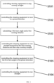
- FIG. 1 is a schematic flowchart of a control method of cleaning equipment according to an embodiment of the present disclosure, which may include: S101, controlling the cleaning equipment to stop running straight.
- a first ADC value collected in real-time by an infrared sensor is acquired, and when the first ADC value is greater than a first preset value, the cleaning equipment is controlled to stop running straight.
- the first preset value may be 1700.
- the cleaning equipment is controlled to turn in the preset direction, and when the cleaning equipment turns, a second ADC value collected in real-time by the infrared sensor is acquired, and the cleaning equipment is controlled to stop turning once the second ADC value is less than a second preset value.
- the second preset value may be 100.
- the preset direction may be either left or right.
- the first turn angle and the first running distance are calculated based on angle data uploaded by an angular velocity sensor; wherein the angular velocity sensor is configured to collect an angle between a running direction of the cleaning equipment and an obstacle ahead.
- the angular velocity sensor may be a gyroscope.
- the cleaning equipment when the first ADC value is greater than the first preset value, the cleaning equipment is controlled to stop running straight, and the angular velocity sensor is controlled to collect an angle between the running direction of the cleaning equipment and the obstacle ahead, and record the angle as a first angle; when the second ADC value is less than the second preset value, the cleaning equipment is controlled to stop turning, the angular velocity sensor is controlled to collect an angle between the running direction of the cleaning equipment and the obstacle ahead, and record the angle as a second angle; the first turn angle is calculated based on the angle data of the first angle and the second angle uploaded by the angular velocity sensor; the first turn angle is an absolute value of a difference between the first angle and the second angle.
- L1 represents the first running distance
- ⁇ 1 represents the first angle
- ⁇ 2 represents the second angle
- S represents a set distance.
- the set distance S may be in a range of: 0.5 D ⁇ S ⁇ 2 D wherein D represents a body width of the cleaning equipment, and a value of D may be 50cm.
- FIGS. 2A and 2B For a better illustration, when a shape of a pool is not a rectangle, a difference of an effect and efficiency between the control method of the present disclosure and a conventional control method, in controlling the cleaning equipment to clean the pool, may refer to FIGS. 2A and 2B .
- FIG. 2A is a schematic diagram of a conventional cleaning path of cleaning equipment in the prior art
- FIG. 2B is a schematic diagram of a cleaning path of cleaning equipment according to an embodiment of the present disclosure .
- the cleaning equipment can only be made turn at a fixed angle of 90 degrees when the cleaning equipment encounters a pool wall, and a head of the cleaning equipment needs to be perpendicular to a side of the pool wall before turning.
- a bottom of the pool is irregular, or when a gyroscope is offset so that the head of the cleaning equipment is not perpendicular to the side of a pool wall, it may result in poor turns.
- a side of the cleaning equipment is not parallel to the side of a pool wall after a 90-degree turn, as shown in a darker area in FIG. 2A , a triangular area near a shorter side of a "square wave" shape will be left uncleaned, which may reduce cleaning efficiency.
- the cleaning equipment When the cleaning equipment is entering the shorter side of the "square wave" shape for cleaning, if the cleaning equipment touches the pool wall, the cleaning equipment may turn in advance, as shown in a circled part of FIG. 2B , resulting in two back and forth paths of the cleaning equipment being too close to each other, and the cleaning equipment almost returns to an original path after turning. Therefore, in the conventional control method, the cleaning equipment is controlled to over-clean a central area of the pool, while a cleaning of a border area of the pool is insufficient, which reduces cleaning efficiency and a cleaning effect.
- the control method of the present disclosure when controlling the cleaning equipment to turn once encountering the pool wall, the head of the cleaning equipment does not need to be perpendicular to the side of the pool wall, and the cleaning equipment does not need to turn according to the fixed angle of 90 degrees, but the cleaning equipment is controlled to turn at a corresponding angle according to an angle between a running direction of the cleaning equipment and an obstacle ahead.
- a running path of the cleaning equipment is very close to the pool wall when encountering a pool wall and turning during cleaning, thereby realizing full coverage cleaning of the pool, solving the problem of missed cleaning caused by conventional control methods.
- control method of the present disclosure ensures that a distance between the two back and forth paths of the cleaning equipment is constant, and may not be changed due to a irregular shape of the pool wall, ensuring that the cleaning path is regular and fully covers the pool, thereby improving the efficiency and effect of cleaning the pool.
- FIG. 3 is a schematic diagram of a path of cleaning equipment turning after encountering a pool wall according to an embodiment of the present disclosure.
- a(1) a first turn angle
- L1 the first running distance
- S a set distance
- the calculation principle of the first running distance L1 can be clearly understood; and according to the above formula, under a premise of different first turn angles a(1), by means of calculating different first running distances L1, it may be ensured that the distance between the two back and forth paths of the cleaning equipment is unchanged, which may be the set distance S, so that the cleaning path of the cleaning equipment can be kept regular and orderly.
- FIG. 4 is a schematic diagram of a structure of a control device of cleaning equipment according to an embodiment of the present disclosure, which may include: a brake module 201, a first turn module 202, a calculation module 203, a run straight module 204, and a second turn module 205.
- the brake module 201 is configured to acquire a first ADC value collected by means of an infrared sensor in real-time when the cleaning equipment is running straight, and control the cleaning equipment to stop running straight when the first ADC value is greater than a first preset value.
- the first preset value may be 1700.
- the first turn module 202 is configured to control the cleaning equipment to turn in a preset direction, acquire a second ADC value collected by means of the infrared sensor in real-time when the cleaning equipment is turning, and control the cleaning equipment to stop turning once the second ADC value is less than a second preset value.
- the second preset value may be 100.
- the preset direction may be either left or right.
- the calculation module 203 is configured to calculate a first turn angle and a first running distance based on angle data uploaded by means of an angular velocity sensor; wherein the angular velocity sensor is configured to collect an angle between a running direction of the cleaning equipment and an obstacle ahead.
- the cleaning equipment when the first ADC value is greater than the first preset value, the cleaning equipment is controlled to stop running straight, and the angular velocity sensor is controlled to collect an angle between the running direction of the cleaning equipment and the obstacle ahead, and record the angle as a first angle; when the second ADC value is less than the second preset value, the cleaning equipment is controlled to stop turning, the angular velocity sensor is controlled to collect an angle between the running direction of the cleaning equipment and the obstacle ahead, and record the angle as a second angle; the first turn angle is calculated based on the angle data of the first angle and the second angle uploaded by the angular velocity sensor; the first turn angle is an absolute value of a difference between the first angle and the second angle.
- L1 represents the first running distance
- ⁇ 1 represents the first angle
- ⁇ 2 represents the second angle
- S represents a set distance.
- the set distance S may be in a range of: 0.5 ⁇ S ⁇ 2 D wherein D represents a body width of the cleaning equipment, and a value of D may be 50cm.
- the run straight module 204 is configured to control the cleaning equipment to run straight forward for the first running distance and then stop running straight.
- the second turn module 205 is configured to control the cleaning equipment to run straight after the cleaning equipment turns the first turn angle in the preset direction.
- the brake module 201 controlling the cleaning equipment to stop running straight, when the collected first ADC value is greater than the first preset value; and then by means of the first turn module 202, controlling the cleaning equipment to turn in a preset direction, then controlling the cleaning equipment to stop turning when the collected second ADC value is less than the second preset value; and then by means of the calculation module 203, calculating the first turn angle and the first running distance; next, by means of the run straight module 204, controlling the cleaning equipment to run straight forward for the first running distance and then stop running straight; finally, by means of the second turn module 205, controlling the cleaning equipment to turn the first turn angle in the preset direction, and then controlling the cleaning equipment to run straight.
- the above control device when a shape of a pool is irregular, may control the cleaning equipment to turn at a corresponding angle based on the angle between the running direction of the cleaning equipment and the obstacle ahead, so as to achieve full coverage cleaning of the irregularly shaped pool; may determine a distance of the cleaning equipment to a pool wall in advance through the ADC value, and when the cleaning equipment is about to touch the pool wall, may reduce a velocity thereof in advance, so that the cleaning equipment will stop before touching the pool wall, so as to ensure that the cleaning equipment runs accurately according to a set path, thus ultimately improving efficiency and precision of the cleaning equipment in cleaning the pool.
Landscapes
- Engineering & Computer Science (AREA)
- Physics & Mathematics (AREA)
- Radar, Positioning & Navigation (AREA)
- Remote Sensing (AREA)
- Aviation & Aerospace Engineering (AREA)
- General Physics & Mathematics (AREA)
- Automation & Control Theory (AREA)
- Architecture (AREA)
- Electromagnetism (AREA)
- Civil Engineering (AREA)
- Structural Engineering (AREA)
- Control Of Position, Course, Altitude, Or Attitude Of Moving Bodies (AREA)
Claims (6)
- Verfahren zur Steuerung von Reinigungsgeräten, wobei das Reinigungsgerät mit einem Infrarotsensor und einem Winkelgeschwindigkeitssensor versehen ist; dadurch gekennzeichnet, dass das Steuerungsverfahren umfasst:Erfassen eines ersten ADC-Werts (Analog-digital-Wandlerwerts), der mithilfe des Infrarotsensors in Echtzeit aufgenommen wird, wenn das Reinigungsgerät geradeaus läuft, und Steuern des Reinigungsgeräts, sodass es aufhört, geradeaus zu laufen (S101), wenn der erste ADC-Wert über einem ersten voreingestellten Wert liegt;Steuern des Reinigungsgeräts, sodass es sich in eine voreingestellte Richtung dreht (S102), und Erfassen eines zweiten ADC-Werts, der mithilfe des Infrarotsensors in Echtzeit aufgenommen wird, und danach Steuern des Reinigungsgeräts, sodass es aufhört, sich zu drehen, sobald der zweite ADC-Wert unter einem zweiten voreingestellten Wert liegt;Berechnen eines ersten Drehwinkels und einer ersten Laufdistanz (S103) auf Grundlage von mithilfe des Winkelgeschwindigkeitssensors hochgeladenen Winkeldaten; wobei der Winkelgeschwindigkeitssensor ausgelegt ist, einen Winkel zwischen einer Laufrichtung des Reinigungsgeräts und einem vorgelagerten Hindernis aufzunehmen;Steuern des Reinigungsgeräts, sodass es die erste Laufdistanz geradeaus nach vorne läuft und danach aufhört, geradeaus zu laufen (S104), danach Steuern des Reinigungsgeräts, sodass es sich um den ersten Drehwinkel in die voreingestellte Richtung (S105) dreht, und danach Steuern des Reinigungsgeräts, sodass es geradeaus läuft (S106).
- Verfahren zur Steuerung von Reinigungsgeräten nach Anspruch 1, dadurch gekennzeichnet, dass das Berechnen des ersten Drehwinkels und der ersten Laufdistanz auf den mithilfe des Winkelgeschwindigkeitssensors hochgeladenen Winkeldaten beruht, wobei das Berechnen des ersten Drehwinkels insbesondere aus Folgendem besteht:wenn der erste ADC-Wert über dem ersten voreingestellten Wert liegt, Steuern des Reinigungsgeräts, sodass es aufhört, geradeaus zu laufen, und Steuern des Winkelgeschwindigkeitssensors, sodass er einen Winkel zwischen der Laufrichtung des Reinigungsgeräts und dem vorgelagerten Hindernis aufnimmt, und Aufzeichnen des Winkels als einen ersten Winkel;Steuern des Reinigungsgeräts, sodass es sich in die voreingestellte Richtung dreht, bis der zweite, mithilfe des Infrarotsensors in Echtzeit aufgenommene ADC-Wert unter dem zweiten voreingestellten Wert liegt, Steuern des Reinigungsgeräts, sodass es aufhört, sich zu drehen, und danach Steuern des Winkelgeschwindigkeitssensors, sodass er einen Winkel zwischen der Laufrichtung des Reinigungsgeräts und dem vorgelagerten Hindernis aufnimmt, und Aufzeichnen des Winkels als einen zweiten Winkel;Berechnen des ersten Drehwinkels auf Grundlage der mithilfe des Winkelgeschwindigkeitssensors hochgeladenen Winkeldaten des ersten Winkels und des zweiten Winkels; wobei der erste Drehwinkel ein Absolutbetrag einer Differenz zwischen dem ersten Winkel und dem zweiten Winkel ist.
- Verfahren zur Steuerung von Reinigungsgeräten nach Anspruch 2, dadurch gekennzeichnet, dass das Berechnen des ersten Drehwinkels und der ersten Laufdistanz auf den mithilfe des Winkelgeschwindigkeitssensors hochgeladenen Winkeldaten beruht, wobei das Berechnen der ersten Laufdistanz insbesondere aus Folgendem besteht:

- Steuervorrichtung für Reinigungsgeräte, wobei das Reinigungsgerät mit einem Infrarotsensor und einem Winkelgeschwindigkeitssensor versehen ist; dadurch gekennzeichnet, dass die Steuervorrichtung umfasst: ein Bremsmodul (201), ein erstes Drehmodul (202), ein Rechenmodul (203), ein Geradelaufmodul (204) und ein zweites Drehmodul (205);wobei das Bremsmodul (201) ausgelegt ist, einen ersten ADC-Wert zu erfassen, der mithilfe des Infrarotsensors in Echtzeit aufgenommen wird, wenn das Reinigungsgerät geradeaus läuft, und das Reinigungsgerät zu steuern, sodass es aufhört, geradeaus zu laufen, wenn der erste ADC-Wert über einem ersten voreingestellten Wert liegt;das erste Drehmodul (202) ausgelegt ist, das Reinigungsgerät zu steuern, sodass es sich in eine voreingestellte Richtung dreht, einen zweiten ADC-Wert zu erfassen, der mithilfe des Infrarotsensors in Echtzeit aufgenommen wird, wenn sich das Reinigungsgerät dreht, und das Reinigungsgerät zu steuern, sodass es aufhört, sich zu drehen, sobald der zweite ADC-Wert unter einem zweiten voreingestellten Wert liegt;das Rechenmodul (203) ausgelegt ist, einen ersten Drehwinkel und eine erste Laufdistanz auf Grundlage von mithilfe des Winkelgeschwindigkeitssensors hochgeladenen Winkeldaten zu berechnen; wobei der Winkelgeschwindigkeitssensor ausgelegt ist, einen Winkel zwischen einer Laufrichtung des Reinigungsgeräts und einem vorgelagerten Hindernis aufzunehmen;das Geradelaufmodul (204) ausgelegt ist, das Reinigungsgerät zu steuern, sodass es die erste Laufdistanz geradeaus nach vorne läuft und danach aufhört, geradeaus zu laufen;das zweite Drehmodul (205) ausgelegt ist, das Reinigungsgerät zu steuern, sodass es sich um den ersten Drehwinkel in die voreingestellte Richtung dreht, und danach das Reinigungsgerät zu steuern, sodass es geradeaus läuft.
- Steuervorrichtung für Reinigungsgeräte nach Anspruch 4, dadurch gekennzeichnet, dass das Rechenmodul (203) ausgelegt ist, den ersten Drehwinkel und die erste Laufdistanz auf Grundlage der mithilfe des Winkelgeschwindigkeitssensors hochgeladenen Winkeldaten zu berechnen, wobei das Berechnen des ersten Drehwinkels insbesondere aus Folgendem besteht:wenn der erste ADC-Wert über dem ersten voreingestellten Wert liegt, Steuern des Reinigungsgeräts, sodass es aufhört, geradeaus zu laufen, und Steuern des Winkelgeschwindigkeitssensors, sodass er einen Winkel zwischen der Laufrichtung des Reinigungsgeräts und dem vorgelagerten Hindernis aufnimmt, und Aufzeichnen des Winkels als einen ersten Winkel;Steuern des Reinigungsgeräts, sodass es sich in die voreingestellte Richtung dreht, bis der zweite, mithilfe des Infrarotsensors in Echtzeit aufgenommene ADC-Wert unter dem zweiten voreingestellten Wert liegt, Steuern des Reinigungsgeräts, sodass es aufhört, sich zu drehen, und danach Steuern des Winkelgeschwindigkeitssensors, sodass er einen Winkel zwischen der Laufrichtung des Reinigungsgeräts und dem vorgelagerten Hindernis aufnimmt, und Aufzeichnen des Winkels als einen zweiten Winkel;Berechnen des ersten Drehwinkels auf Grundlage der mithilfe des Winkelgeschwindigkeitssensors hochgeladenen Winkeldaten des ersten Winkels und des zweiten Winkels; wobei der erste Drehwinkel ein Absolutbetrag einer Differenz zwischen dem ersten Winkel und dem zweiten Winkel ist.
- Steuervorrichtung für Reinigungsgeräte nach Anspruch 5, dadurch gekennzeichnet, dass das Rechenmodul (203) ausgelegt ist, den ersten Drehwinkel und die erste Laufdistanz auf Grundlage der mithilfe des Winkelgeschwindigkeitssensors hochgeladenen Winkeldaten zu berechnen, wobei das Berechnen der ersten Laufdistanz insbesondere aus Folgendem besteht:

Applications Claiming Priority (2)
| Application Number | Priority Date | Filing Date | Title |
|---|---|---|---|
| CN202110069981.5A CN112947408B (zh) | 2021-01-19 | 2021-01-19 | 一种清洁设备的控制方法及装置 |
| PCT/CN2021/083435 WO2022156062A1 (zh) | 2021-01-19 | 2021-03-26 | 一种清洁设备的控制方法及装置 |
Publications (5)
| Publication Number | Publication Date |
|---|---|
| EP4059403A1 EP4059403A1 (de) | 2022-09-21 |
| EP4059403A4 EP4059403A4 (de) | 2023-01-25 |
| EP4059403B1 true EP4059403B1 (de) | 2023-11-08 |
| EP4059403C0 EP4059403C0 (de) | 2023-11-08 |
| EP4059403B8 EP4059403B8 (de) | 2023-12-27 |
Family
ID=82405075
Family Applications (1)
| Application Number | Title | Priority Date | Filing Date |
|---|---|---|---|
| EP21867901.7A Active EP4059403B8 (de) | 2021-01-19 | 2021-03-26 | Steuerverfahren und steuervorrichtung eines reinigungsgeräts |
Country Status (2)
| Country | Link |
|---|---|
| US (1) | US12443189B2 (de) |
| EP (1) | EP4059403B8 (de) |
Families Citing this family (1)
| Publication number | Priority date | Publication date | Assignee | Title |
|---|---|---|---|---|
| CN118819153A (zh) * | 2024-06-27 | 2024-10-22 | 深圳市元鼎智能创新有限公司 | 清洁设备在避障时的控制方法和装置 |
Family Cites Families (16)
| Publication number | Priority date | Publication date | Assignee | Title |
|---|---|---|---|---|
| JP2006268498A (ja) * | 2005-03-24 | 2006-10-05 | Funai Electric Co Ltd | 自走式掃除機 |
| KR20080075051A (ko) * | 2007-02-10 | 2008-08-14 | 삼성전자주식회사 | 로봇 청소기 및 그 제어방법 |
| KR100919698B1 (ko) * | 2007-08-14 | 2009-09-29 | 포항공과대학교 산학협력단 | 로봇청소기를 이용한 청소방법 |
| WO2020110105A1 (en) * | 2018-11-27 | 2020-06-04 | Aquatron Robotic Technology Ltd. | Concurrent operation of multiple robotic pool cleaners |
| WO2017216784A1 (en) * | 2016-09-08 | 2017-12-21 | Aquatron Robotic Technology Ltd. | Navigation of robotic pool cleaner |
| CN108247647B (zh) * | 2018-01-24 | 2021-06-22 | 速感科技(北京)有限公司 | 一种清洁机器人 |
| CN108196555B (zh) * | 2018-03-09 | 2019-11-05 | 珠海市一微半导体有限公司 | 自主移动机器人沿边行走的控制方法 |
| US11141863B2 (en) * | 2018-10-11 | 2021-10-12 | Pixart Imaging Inc. | Cleaning robot capable of detecting 2D depth information and operating method thereof |
| CN109464075A (zh) * | 2018-12-07 | 2019-03-15 | 江苏美的清洁电器股份有限公司 | 扫地机器人的清扫控制方法及其装置和扫地机器人 |
| CN109567678B (zh) | 2018-12-07 | 2022-03-04 | 美智纵横科技有限责任公司 | 扫地机器人的清扫控制方法及其装置和扫地机器人 |
| CN109407670B (zh) * | 2018-12-07 | 2022-03-04 | 美智纵横科技有限责任公司 | 扫地机器人的距离探测方法及其装置和扫地机器人 |
| US11353884B2 (en) * | 2019-01-28 | 2022-06-07 | Pixart Imaging Inc. | Robot without detection dead zone |
| CN110192812A (zh) * | 2019-05-15 | 2019-09-03 | 深圳市银星智能科技股份有限公司 | 一种沿边跟随清洁的方法及清洁机器人 |
| CN110338715B (zh) * | 2019-07-11 | 2021-01-26 | 珠海市一微半导体有限公司 | 智能机器人清洁地面的方法和芯片以及清洁机器人 |
| CN111802962A (zh) * | 2020-06-30 | 2020-10-23 | 深圳乐动机器人有限公司 | 一种机器人清洁的方法、装置、机器人及存储介质 |
| CN116250755A (zh) * | 2021-12-10 | 2023-06-13 | 科沃斯机器人股份有限公司 | 清洁路径确定方法、系统、设备及存储介质 |
-
2021
- 2021-03-26 EP EP21867901.7A patent/EP4059403B8/de active Active
-
2022
- 2022-03-22 US US17/701,652 patent/US12443189B2/en active Active
Also Published As
| Publication number | Publication date |
|---|---|
| EP4059403A4 (de) | 2023-01-25 |
| EP4059403B8 (de) | 2023-12-27 |
| US12443189B2 (en) | 2025-10-14 |
| EP4059403A1 (de) | 2022-09-21 |
| US20220229440A1 (en) | 2022-07-21 |
| EP4059403C0 (de) | 2023-11-08 |
Similar Documents
| Publication | Publication Date | Title |
|---|---|---|
| EP4059407B1 (de) | Reinigungssteuerverfahren basierend auf dichten hindernissen | |
| CN108634886B (zh) | 机器人清扫中断后的控制方法及芯片 | |
| WO2022156062A1 (zh) | 一种清洁设备的控制方法及装置 | |
| CN107703930B (zh) | 机器人的续扫控制方法 | |
| CN107390698B (zh) | 扫地机器人的补扫方法及芯片 | |
| CN101559513B (zh) | 基于激光测距的集装箱波纹板焊接轨迹检测与控制方法 | |
| CN108078503B (zh) | 自移动机器人的清扫方法和系统 | |
| CN107544517A (zh) | 智能清洁机器人的控制方法 | |
| CN110580047A (zh) | 一种自主机器人的防跌落行进方法及自主机器人 | |
| EP4059403B1 (de) | Verfahren und vorrichtung zur steuerung einer reinigungsvorrichtung | |
| CN101916110A (zh) | 一种清扫机器人和清扫机器人的行走控制方法 | |
| WO2009138140A2 (de) | Ansteuerverfahren für ein roboterfahrzeug sowie roboterfahrzeug | |
| CN107443385A (zh) | 基于视觉的机器人直线导航的检测方法和芯片及机器人 | |
| CN115990880B (zh) | 机器人航向调整方法、机器人、装置及计算机存储介质 | |
| US20260072437A1 (en) | Motion control method for adaptive self-reconfigurable pipeline robot based on environmental perception | |
| US20260044156A1 (en) | Control Method for Autonomous Moving Device, Storage Medium and Autonomous Moving Device | |
| CN111897336A (zh) | 一种机器人沿边行为结束的判断方法、芯片及机器人 | |
| CN110731734A (zh) | 智能机器人规划清扫的控制方法和芯片及清洁机器人 | |
| CN120169776A (zh) | 水位线清洁方法、装置、水下清洁机器人及存储介质 | |
| CN112137512B (zh) | 扫地机器人清扫区域检测方法、装置、设备、系统和介质 | |
| CN119935113A (zh) | 泳池水上地图创建方法及泳池清洁设备 | |
| CN108613656B (zh) | 机器人基于六轴陀螺仪检测被卡的方法 | |
| CN114216458A (zh) | 基于多传感器融合的智能推料机器人组合导航系统及方法 | |
| WO2023104087A1 (zh) | 自动工作系统、自动工作方法和计算机可读存储介质 | |
| CN116382275A (zh) | 自移动设备的状态识别方法、自移动设备及存储介质 |
Legal Events
| Date | Code | Title | Description |
|---|---|---|---|
| STAA | Information on the status of an ep patent application or granted ep patent |
Free format text: STATUS: UNKNOWN |
|
| STAA | Information on the status of an ep patent application or granted ep patent |
Free format text: STATUS: THE INTERNATIONAL PUBLICATION HAS BEEN MADE |
|
| PUAI | Public reference made under article 153(3) epc to a published international application that has entered the european phase |
Free format text: ORIGINAL CODE: 0009012 |
|
| STAA | Information on the status of an ep patent application or granted ep patent |
Free format text: STATUS: REQUEST FOR EXAMINATION WAS MADE |
|
| 17P | Request for examination filed |
Effective date: 20220324 |
|
| AK | Designated contracting states |
Kind code of ref document: A1 Designated state(s): AL AT BE BG CH CY CZ DE DK EE ES FI FR GB GR HR HU IE IS IT LI LT LU LV MC MK MT NL NO PL PT RO RS SE SI SK SM TR |
|
| A4 | Supplementary search report drawn up and despatched |
Effective date: 20221223 |
|
| RIC1 | Information provided on ipc code assigned before grant |
Ipc: E04H 4/16 20060101ALI20221219BHEP Ipc: G05D 1/02 20200101ALI20221219BHEP Ipc: A47L 11/00 20060101AFI20221219BHEP |
|
| GRAP | Despatch of communication of intention to grant a patent |
Free format text: ORIGINAL CODE: EPIDOSNIGR1 |
|
| STAA | Information on the status of an ep patent application or granted ep patent |
Free format text: STATUS: GRANT OF PATENT IS INTENDED |
|
| DAV | Request for validation of the european patent (deleted) | ||
| DAX | Request for extension of the european patent (deleted) | ||
| INTG | Intention to grant announced |
Effective date: 20230526 |
|
| GRAS | Grant fee paid |
Free format text: ORIGINAL CODE: EPIDOSNIGR3 |
|
| GRAA | (expected) grant |
Free format text: ORIGINAL CODE: 0009210 |
|
| STAA | Information on the status of an ep patent application or granted ep patent |
Free format text: STATUS: THE PATENT HAS BEEN GRANTED |
|
| AK | Designated contracting states |
Kind code of ref document: B1 Designated state(s): AL AT BE BG CH CY CZ DE DK EE ES FI FR GB GR HR HU IE IS IT LI LT LU LV MC MK MT NL NO PL PT RO RS SE SI SK SM TR |
|
| REG | Reference to a national code |
Ref country code: GB Ref legal event code: FG4D |
|
| REG | Reference to a national code |
Ref country code: CH Ref legal event code: EP |
|
| REG | Reference to a national code |
Ref country code: DE Ref legal event code: R096 Ref document number: 602021006708 Country of ref document: DE |
|
| REG | Reference to a national code |
Ref country code: CH Ref legal event code: PK Free format text: TITEL Ref country code: CH Ref legal event code: PK Free format text: BERICHTIGUNG B8 |
|
| REG | Reference to a national code |
Ref country code: IE Ref legal event code: FG4D |
|
| U01 | Request for unitary effect filed |
Effective date: 20231208 |
|
| U07 | Unitary effect registered |
Designated state(s): AT BE BG DE DK EE FI FR IT LT LU LV MT NL PT SE SI Effective date: 20231214 |
|
| PG25 | Lapsed in a contracting state [announced via postgrant information from national office to epo] |
Ref country code: IS Free format text: LAPSE BECAUSE OF FAILURE TO SUBMIT A TRANSLATION OF THE DESCRIPTION OR TO PAY THE FEE WITHIN THE PRESCRIBED TIME-LIMIT Effective date: 20240308 |
|
| U20 | Renewal fee for the european patent with unitary effect paid |
Year of fee payment: 4 Effective date: 20240320 |
|
| PG25 | Lapsed in a contracting state [announced via postgrant information from national office to epo] |
Ref country code: ES Free format text: LAPSE BECAUSE OF FAILURE TO SUBMIT A TRANSLATION OF THE DESCRIPTION OR TO PAY THE FEE WITHIN THE PRESCRIBED TIME-LIMIT Effective date: 20231108 |
|
| PG25 | Lapsed in a contracting state [announced via postgrant information from national office to epo] |
Ref country code: IS Free format text: LAPSE BECAUSE OF FAILURE TO SUBMIT A TRANSLATION OF THE DESCRIPTION OR TO PAY THE FEE WITHIN THE PRESCRIBED TIME-LIMIT Effective date: 20240308 Ref country code: ES Free format text: LAPSE BECAUSE OF FAILURE TO SUBMIT A TRANSLATION OF THE DESCRIPTION OR TO PAY THE FEE WITHIN THE PRESCRIBED TIME-LIMIT Effective date: 20231108 |
|
| PG25 | Lapsed in a contracting state [announced via postgrant information from national office to epo] |
Ref country code: RS Free format text: LAPSE BECAUSE OF FAILURE TO SUBMIT A TRANSLATION OF THE DESCRIPTION OR TO PAY THE FEE WITHIN THE PRESCRIBED TIME-LIMIT Effective date: 20231108 Ref country code: PL Free format text: LAPSE BECAUSE OF FAILURE TO SUBMIT A TRANSLATION OF THE DESCRIPTION OR TO PAY THE FEE WITHIN THE PRESCRIBED TIME-LIMIT Effective date: 20231108 Ref country code: NO Free format text: LAPSE BECAUSE OF FAILURE TO SUBMIT A TRANSLATION OF THE DESCRIPTION OR TO PAY THE FEE WITHIN THE PRESCRIBED TIME-LIMIT Effective date: 20240208 Ref country code: HR Free format text: LAPSE BECAUSE OF FAILURE TO SUBMIT A TRANSLATION OF THE DESCRIPTION OR TO PAY THE FEE WITHIN THE PRESCRIBED TIME-LIMIT Effective date: 20231108 |
|
| PG25 | Lapsed in a contracting state [announced via postgrant information from national office to epo] |
Ref country code: CZ Free format text: LAPSE BECAUSE OF FAILURE TO SUBMIT A TRANSLATION OF THE DESCRIPTION OR TO PAY THE FEE WITHIN THE PRESCRIBED TIME-LIMIT Effective date: 20231108 |
|
| PG25 | Lapsed in a contracting state [announced via postgrant information from national office to epo] |
Ref country code: SK Free format text: LAPSE BECAUSE OF FAILURE TO SUBMIT A TRANSLATION OF THE DESCRIPTION OR TO PAY THE FEE WITHIN THE PRESCRIBED TIME-LIMIT Effective date: 20231108 |
|
| PG25 | Lapsed in a contracting state [announced via postgrant information from national office to epo] |
Ref country code: SM Free format text: LAPSE BECAUSE OF FAILURE TO SUBMIT A TRANSLATION OF THE DESCRIPTION OR TO PAY THE FEE WITHIN THE PRESCRIBED TIME-LIMIT Effective date: 20231108 Ref country code: SK Free format text: LAPSE BECAUSE OF FAILURE TO SUBMIT A TRANSLATION OF THE DESCRIPTION OR TO PAY THE FEE WITHIN THE PRESCRIBED TIME-LIMIT Effective date: 20231108 Ref country code: RO Free format text: LAPSE BECAUSE OF FAILURE TO SUBMIT A TRANSLATION OF THE DESCRIPTION OR TO PAY THE FEE WITHIN THE PRESCRIBED TIME-LIMIT Effective date: 20231108 Ref country code: CZ Free format text: LAPSE BECAUSE OF FAILURE TO SUBMIT A TRANSLATION OF THE DESCRIPTION OR TO PAY THE FEE WITHIN THE PRESCRIBED TIME-LIMIT Effective date: 20231108 |
|
| REG | Reference to a national code |
Ref country code: DE Ref legal event code: R097 Ref document number: 602021006708 Country of ref document: DE |
|
| PLBE | No opposition filed within time limit |
Free format text: ORIGINAL CODE: 0009261 |
|
| STAA | Information on the status of an ep patent application or granted ep patent |
Free format text: STATUS: NO OPPOSITION FILED WITHIN TIME LIMIT |
|
| 26N | No opposition filed |
Effective date: 20240809 |
|
| REG | Reference to a national code |
Ref country code: CH Ref legal event code: PL |
|
| PG25 | Lapsed in a contracting state [announced via postgrant information from national office to epo] |
Ref country code: MC Free format text: LAPSE BECAUSE OF FAILURE TO SUBMIT A TRANSLATION OF THE DESCRIPTION OR TO PAY THE FEE WITHIN THE PRESCRIBED TIME-LIMIT Effective date: 20231108 |
|
| PG25 | Lapsed in a contracting state [announced via postgrant information from national office to epo] |
Ref country code: MC Free format text: LAPSE BECAUSE OF FAILURE TO SUBMIT A TRANSLATION OF THE DESCRIPTION OR TO PAY THE FEE WITHIN THE PRESCRIBED TIME-LIMIT Effective date: 20231108 |
|
| PG25 | Lapsed in a contracting state [announced via postgrant information from national office to epo] |
Ref country code: IE Free format text: LAPSE BECAUSE OF NON-PAYMENT OF DUE FEES Effective date: 20240326 |
|
| PG25 | Lapsed in a contracting state [announced via postgrant information from national office to epo] |
Ref country code: IE Free format text: LAPSE BECAUSE OF NON-PAYMENT OF DUE FEES Effective date: 20240326 Ref country code: CH Free format text: LAPSE BECAUSE OF NON-PAYMENT OF DUE FEES Effective date: 20240331 |
|
| U20 | Renewal fee for the european patent with unitary effect paid |
Year of fee payment: 5 Effective date: 20250122 |
|
| PG25 | Lapsed in a contracting state [announced via postgrant information from national office to epo] |
Ref country code: CY Free format text: LAPSE BECAUSE OF FAILURE TO SUBMIT A TRANSLATION OF THE DESCRIPTION OR TO PAY THE FEE WITHIN THE PRESCRIBED TIME-LIMIT; INVALID AB INITIO Effective date: 20210326 |
|
| PG25 | Lapsed in a contracting state [announced via postgrant information from national office to epo] |
Ref country code: HU Free format text: LAPSE BECAUSE OF FAILURE TO SUBMIT A TRANSLATION OF THE DESCRIPTION OR TO PAY THE FEE WITHIN THE PRESCRIBED TIME-LIMIT; INVALID AB INITIO Effective date: 20210326 |
|
| PG25 | Lapsed in a contracting state [announced via postgrant information from national office to epo] |
Ref country code: GR Free format text: LAPSE BECAUSE OF FAILURE TO SUBMIT A TRANSLATION OF THE DESCRIPTION OR TO PAY THE FEE WITHIN THE PRESCRIBED TIME-LIMIT; INVALID AB INITIO Effective date: 20210326 |
|
| GBPC | Gb: european patent ceased through non-payment of renewal fee |
Effective date: 20250326 |
|
| PG25 | Lapsed in a contracting state [announced via postgrant information from national office to epo] |
Ref country code: TR Free format text: LAPSE BECAUSE OF FAILURE TO SUBMIT A TRANSLATION OF THE DESCRIPTION OR TO PAY THE FEE WITHIN THE PRESCRIBED TIME-LIMIT Effective date: 20231108 |
|
| PG25 | Lapsed in a contracting state [announced via postgrant information from national office to epo] |
Ref country code: GB Free format text: LAPSE BECAUSE OF NON-PAYMENT OF DUE FEES Effective date: 20250326 |
|
| U20 | Renewal fee for the european patent with unitary effect paid |
Year of fee payment: 6 Effective date: 20260120 |