EP4059403B1 - Method and apparatus for controlling cleaning device - Google Patents
Method and apparatus for controlling cleaning device Download PDFInfo
- Publication number
- EP4059403B1 EP4059403B1 EP21867901.7A EP21867901A EP4059403B1 EP 4059403 B1 EP4059403 B1 EP 4059403B1 EP 21867901 A EP21867901 A EP 21867901A EP 4059403 B1 EP4059403 B1 EP 4059403B1
- Authority
- EP
- European Patent Office
- Prior art keywords
- angle
- cleaning equipment
- turn
- running
- controlling
- Prior art date
- Legal status (The legal status is an assumption and is not a legal conclusion. Google has not performed a legal analysis and makes no representation as to the accuracy of the status listed.)
- Active
Links
- 238000004140 cleaning Methods 0.000 title claims description 218
- 238000000034 method Methods 0.000 title claims description 25
- 238000010586 diagram Methods 0.000 description 8
- 230000001788 irregular Effects 0.000 description 4
- 230000000694 effects Effects 0.000 description 3
- 230000009286 beneficial effect Effects 0.000 description 1
- 238000011010 flushing procedure Methods 0.000 description 1
- 239000002699 waste material Substances 0.000 description 1
Images


Classifications
-
- G—PHYSICS
- G05—CONTROLLING; REGULATING
- G05D—SYSTEMS FOR CONTROLLING OR REGULATING NON-ELECTRIC VARIABLES
- G05D1/00—Control of position, course, altitude or attitude of land, water, air or space vehicles, e.g. using automatic pilots
- G05D1/02—Control of position or course in two dimensions
- G05D1/021—Control of position or course in two dimensions specially adapted to land vehicles
- G05D1/0212—Control of position or course in two dimensions specially adapted to land vehicles with means for defining a desired trajectory
- G05D1/0214—Control of position or course in two dimensions specially adapted to land vehicles with means for defining a desired trajectory in accordance with safety or protection criteria, e.g. avoiding hazardous areas
-
- G—PHYSICS
- G05—CONTROLLING; REGULATING
- G05D—SYSTEMS FOR CONTROLLING OR REGULATING NON-ELECTRIC VARIABLES
- G05D1/00—Control of position, course, altitude or attitude of land, water, air or space vehicles, e.g. using automatic pilots
- G05D1/02—Control of position or course in two dimensions
- G05D1/021—Control of position or course in two dimensions specially adapted to land vehicles
- G05D1/0231—Control of position or course in two dimensions specially adapted to land vehicles using optical position detecting means
- G05D1/0242—Control of position or course in two dimensions specially adapted to land vehicles using optical position detecting means using non-visible light signals, e.g. IR or UV signals
-
- E—FIXED CONSTRUCTIONS
- E04—BUILDING
- E04H—BUILDINGS OR LIKE STRUCTURES FOR PARTICULAR PURPOSES; SWIMMING OR SPLASH BATHS OR POOLS; MASTS; FENCING; TENTS OR CANOPIES, IN GENERAL
- E04H4/00—Swimming or splash baths or pools
- E04H4/14—Parts, details or accessories not otherwise provided for
- E04H4/16—Parts, details or accessories not otherwise provided for specially adapted for cleaning
- E04H4/1654—Self-propelled cleaners
-
- G—PHYSICS
- G05—CONTROLLING; REGULATING
- G05D—SYSTEMS FOR CONTROLLING OR REGULATING NON-ELECTRIC VARIABLES
- G05D1/00—Control of position, course, altitude or attitude of land, water, air or space vehicles, e.g. using automatic pilots
- G05D1/02—Control of position or course in two dimensions
- G05D1/021—Control of position or course in two dimensions specially adapted to land vehicles
- G05D1/0212—Control of position or course in two dimensions specially adapted to land vehicles with means for defining a desired trajectory
- G05D1/0219—Control of position or course in two dimensions specially adapted to land vehicles with means for defining a desired trajectory ensuring the processing of the whole working surface
-
- G—PHYSICS
- G05—CONTROLLING; REGULATING
- G05D—SYSTEMS FOR CONTROLLING OR REGULATING NON-ELECTRIC VARIABLES
- G05D1/00—Control of position, course, altitude or attitude of land, water, air or space vehicles, e.g. using automatic pilots
- G05D1/02—Control of position or course in two dimensions
- G05D1/021—Control of position or course in two dimensions specially adapted to land vehicles
- G05D1/0212—Control of position or course in two dimensions specially adapted to land vehicles with means for defining a desired trajectory
- G05D1/0223—Control of position or course in two dimensions specially adapted to land vehicles with means for defining a desired trajectory involving speed control of the vehicle
-
- G—PHYSICS
- G05—CONTROLLING; REGULATING
- G05D—SYSTEMS FOR CONTROLLING OR REGULATING NON-ELECTRIC VARIABLES
- G05D1/00—Control of position, course, altitude or attitude of land, water, air or space vehicles, e.g. using automatic pilots
- G05D1/02—Control of position or course in two dimensions
- G05D1/021—Control of position or course in two dimensions specially adapted to land vehicles
- G05D1/0268—Control of position or course in two dimensions specially adapted to land vehicles using internal positioning means
- G05D1/027—Control of position or course in two dimensions specially adapted to land vehicles using internal positioning means comprising intertial navigation means, e.g. azimuth detector
Definitions
- the present disclosure relates to a field of robot control, in particular to a control method and a control device of cleaning equipment.
- conventional cleaning equipment in the prior art can only perform a "square wave" shaped cleaning path with a 90-degree turn.
- the conventional cleaning equipment is only suitable for a rectangular pool.
- a side of the cleaning equipment is not parallel to a side of a pool wall after a 90-degree turn of the cleaning equipment, leaving some areas near a shorter side of the "square wave” shape not cleaned, resulting in over-cleaning in a central area of the pool, and insufficient cleaning in a border area of the pool, resulting in a low cleaning efficiency.
- the cleaning equipment in the prior art determines whether it touches the pool wall or not only by means of a gyroscope, and cannot measure a distance and an angle to the pool wall in advance.
- the cleaning equipment performs a brake after touching the pool wall, which causes a posture and a path of the cleaning equipment to change and deviate at the moment of the touching, resulting in a deviation from a preset path of the cleaning equipment.
- CN111802962A disclosed a method, device, robot and storage medium for robot cleaning, wherein the method for robot cleaning includes determining the motion direction of the robot, performing a square wave shaped cleaning along the motion direction of the area to be cleaned, the square wave shaped cleaning includes radial cleaning and border cleaning, radial cleaning is to perform intra-area cleaning along the longitudinal direction of the square wave shaped cleaning, and border cleaning includes axial border cleaning, radial border cleaning, and tangential border cleaning.
- Axial border cleaning means border cleaning along the transverse direction of the square wave shape.
- Radial border cleaning means border cleaning along the longitudinal direction of the square wave shape.
- Tangential border cleaning means border cleaning along the tangential direction of the inner edge of the area to be cleaned.
- the projection length of the border cleaning path in the transverse direction of the square wave shape does not exceed the first preset value. This application can not only save the total cleaning time and improve the cleaning efficiency, but also avoid long-distance border cleaning, thus saving costs.
- the present disclosure provides a control method and a control device of cleaning equipment, and the control method improves efficiency and precision of the cleaning equipment in cleaning pools.
- a first aspect of embodiments of the present disclosure provides a control method of cleaning equipment, wherein the cleaning equipment is provided with an infrared sensor and an angular velocity sensor; the control method may include: when the cleaning equipment is running straight, acquiring a first ADC(analog to digital converter) value collected by means of the infrared sensor in real-time, and when the first ADC value is greater than a first preset value, controlling the cleaning equipment to stop running straight;
- calculating the first turn angle and the first running distance based on the angle data uploaded by means of the angular velocity sensor, wherein the calculating the first turn angle may be specifically:
- a second aspect of the embodiments of the present disclosure provides a control device of the cleaning equipment, wherein the cleaning equipment may be provided with an infrared sensor and an angular velocity sensor; the control device may include: a brake module, a first turn module, a calculation module, a run straight module, and a second turn module;
- the calculation module may be configured to calculate the first turn angle and the first running distance based on the angle data uploaded by means of the angular velocity sensor, wherein the calculate the first turn angle may be specifically:
- control method and a control device of cleaning equipment provided by the embodiments of the present disclosure have beneficial effects of, the control method according to the embodiments of the present disclosure may include: controlling the cleaning equipment to stop running straight, when a collected first ADC value is greater than a first preset value; and then controlling the cleaning equipment to turn in a preset direction, then controlling the cleaning equipment to stop turning, when a collected second ADC value is less than a second preset value; and then calculating a first turn angle and a first running distance; next, controlling the cleaning equipment to run straight forward for the first running distance and then stop running straight, then controlling the cleaning equipment to turn the first turn angle in the preset direction, and finally controlling the cleaning equipment to run straight.
- the cleaning equipment when a shape of a pool is irregular, the cleaning equipment may be controlled to turn at a corresponding angle based on an angle between a running direction of the cleaning equipment and an obstacle ahead, so as to achieve full coverage cleaning of the irregularly shaped pool; a distance of the cleaning equipment to a pool wall may be determined in advance through the ADC value, when the cleaning equipment is about to touch the pool wall, a velocity thereof may be reduced in advance, so that the cleaning equipment will stop before touching the pool wall, so as to ensure that the cleaning equipment runs accurately according to a set path, thus ultimately improving efficiency and precision of the cleaning equipment in cleaning the pool.
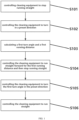
- FIG. 1 is a schematic flowchart of a control method of cleaning equipment according to an embodiment of the present disclosure, which may include: S101, controlling the cleaning equipment to stop running straight.
- a first ADC value collected in real-time by an infrared sensor is acquired, and when the first ADC value is greater than a first preset value, the cleaning equipment is controlled to stop running straight.
- the first preset value may be 1700.
- the cleaning equipment is controlled to turn in the preset direction, and when the cleaning equipment turns, a second ADC value collected in real-time by the infrared sensor is acquired, and the cleaning equipment is controlled to stop turning once the second ADC value is less than a second preset value.
- the second preset value may be 100.
- the preset direction may be either left or right.
- the first turn angle and the first running distance are calculated based on angle data uploaded by an angular velocity sensor; wherein the angular velocity sensor is configured to collect an angle between a running direction of the cleaning equipment and an obstacle ahead.
- the angular velocity sensor may be a gyroscope.
- the cleaning equipment when the first ADC value is greater than the first preset value, the cleaning equipment is controlled to stop running straight, and the angular velocity sensor is controlled to collect an angle between the running direction of the cleaning equipment and the obstacle ahead, and record the angle as a first angle; when the second ADC value is less than the second preset value, the cleaning equipment is controlled to stop turning, the angular velocity sensor is controlled to collect an angle between the running direction of the cleaning equipment and the obstacle ahead, and record the angle as a second angle; the first turn angle is calculated based on the angle data of the first angle and the second angle uploaded by the angular velocity sensor; the first turn angle is an absolute value of a difference between the first angle and the second angle.
- L1 represents the first running distance
- ⁇ 1 represents the first angle
- ⁇ 2 represents the second angle
- S represents a set distance.
- the set distance S may be in a range of: 0.5 D ⁇ S ⁇ 2 D wherein D represents a body width of the cleaning equipment, and a value of D may be 50cm.
- FIGS. 2A and 2B For a better illustration, when a shape of a pool is not a rectangle, a difference of an effect and efficiency between the control method of the present disclosure and a conventional control method, in controlling the cleaning equipment to clean the pool, may refer to FIGS. 2A and 2B .
- FIG. 2A is a schematic diagram of a conventional cleaning path of cleaning equipment in the prior art
- FIG. 2B is a schematic diagram of a cleaning path of cleaning equipment according to an embodiment of the present disclosure .
- the cleaning equipment can only be made turn at a fixed angle of 90 degrees when the cleaning equipment encounters a pool wall, and a head of the cleaning equipment needs to be perpendicular to a side of the pool wall before turning.
- a bottom of the pool is irregular, or when a gyroscope is offset so that the head of the cleaning equipment is not perpendicular to the side of a pool wall, it may result in poor turns.
- a side of the cleaning equipment is not parallel to the side of a pool wall after a 90-degree turn, as shown in a darker area in FIG. 2A , a triangular area near a shorter side of a "square wave" shape will be left uncleaned, which may reduce cleaning efficiency.
- the cleaning equipment When the cleaning equipment is entering the shorter side of the "square wave" shape for cleaning, if the cleaning equipment touches the pool wall, the cleaning equipment may turn in advance, as shown in a circled part of FIG. 2B , resulting in two back and forth paths of the cleaning equipment being too close to each other, and the cleaning equipment almost returns to an original path after turning. Therefore, in the conventional control method, the cleaning equipment is controlled to over-clean a central area of the pool, while a cleaning of a border area of the pool is insufficient, which reduces cleaning efficiency and a cleaning effect.
- the control method of the present disclosure when controlling the cleaning equipment to turn once encountering the pool wall, the head of the cleaning equipment does not need to be perpendicular to the side of the pool wall, and the cleaning equipment does not need to turn according to the fixed angle of 90 degrees, but the cleaning equipment is controlled to turn at a corresponding angle according to an angle between a running direction of the cleaning equipment and an obstacle ahead.
- a running path of the cleaning equipment is very close to the pool wall when encountering a pool wall and turning during cleaning, thereby realizing full coverage cleaning of the pool, solving the problem of missed cleaning caused by conventional control methods.
- control method of the present disclosure ensures that a distance between the two back and forth paths of the cleaning equipment is constant, and may not be changed due to a irregular shape of the pool wall, ensuring that the cleaning path is regular and fully covers the pool, thereby improving the efficiency and effect of cleaning the pool.
- FIG. 3 is a schematic diagram of a path of cleaning equipment turning after encountering a pool wall according to an embodiment of the present disclosure.
- a(1) a first turn angle
- L1 the first running distance
- S a set distance
- the calculation principle of the first running distance L1 can be clearly understood; and according to the above formula, under a premise of different first turn angles a(1), by means of calculating different first running distances L1, it may be ensured that the distance between the two back and forth paths of the cleaning equipment is unchanged, which may be the set distance S, so that the cleaning path of the cleaning equipment can be kept regular and orderly.
- FIG. 4 is a schematic diagram of a structure of a control device of cleaning equipment according to an embodiment of the present disclosure, which may include: a brake module 201, a first turn module 202, a calculation module 203, a run straight module 204, and a second turn module 205.
- the brake module 201 is configured to acquire a first ADC value collected by means of an infrared sensor in real-time when the cleaning equipment is running straight, and control the cleaning equipment to stop running straight when the first ADC value is greater than a first preset value.
- the first preset value may be 1700.
- the first turn module 202 is configured to control the cleaning equipment to turn in a preset direction, acquire a second ADC value collected by means of the infrared sensor in real-time when the cleaning equipment is turning, and control the cleaning equipment to stop turning once the second ADC value is less than a second preset value.
- the second preset value may be 100.
- the preset direction may be either left or right.
- the calculation module 203 is configured to calculate a first turn angle and a first running distance based on angle data uploaded by means of an angular velocity sensor; wherein the angular velocity sensor is configured to collect an angle between a running direction of the cleaning equipment and an obstacle ahead.
- the cleaning equipment when the first ADC value is greater than the first preset value, the cleaning equipment is controlled to stop running straight, and the angular velocity sensor is controlled to collect an angle between the running direction of the cleaning equipment and the obstacle ahead, and record the angle as a first angle; when the second ADC value is less than the second preset value, the cleaning equipment is controlled to stop turning, the angular velocity sensor is controlled to collect an angle between the running direction of the cleaning equipment and the obstacle ahead, and record the angle as a second angle; the first turn angle is calculated based on the angle data of the first angle and the second angle uploaded by the angular velocity sensor; the first turn angle is an absolute value of a difference between the first angle and the second angle.
- L1 represents the first running distance
- ⁇ 1 represents the first angle
- ⁇ 2 represents the second angle
- S represents a set distance.
- the set distance S may be in a range of: 0.5 ⁇ S ⁇ 2 D wherein D represents a body width of the cleaning equipment, and a value of D may be 50cm.
- the run straight module 204 is configured to control the cleaning equipment to run straight forward for the first running distance and then stop running straight.
- the second turn module 205 is configured to control the cleaning equipment to run straight after the cleaning equipment turns the first turn angle in the preset direction.
- the brake module 201 controlling the cleaning equipment to stop running straight, when the collected first ADC value is greater than the first preset value; and then by means of the first turn module 202, controlling the cleaning equipment to turn in a preset direction, then controlling the cleaning equipment to stop turning when the collected second ADC value is less than the second preset value; and then by means of the calculation module 203, calculating the first turn angle and the first running distance; next, by means of the run straight module 204, controlling the cleaning equipment to run straight forward for the first running distance and then stop running straight; finally, by means of the second turn module 205, controlling the cleaning equipment to turn the first turn angle in the preset direction, and then controlling the cleaning equipment to run straight.
- the above control device when a shape of a pool is irregular, may control the cleaning equipment to turn at a corresponding angle based on the angle between the running direction of the cleaning equipment and the obstacle ahead, so as to achieve full coverage cleaning of the irregularly shaped pool; may determine a distance of the cleaning equipment to a pool wall in advance through the ADC value, and when the cleaning equipment is about to touch the pool wall, may reduce a velocity thereof in advance, so that the cleaning equipment will stop before touching the pool wall, so as to ensure that the cleaning equipment runs accurately according to a set path, thus ultimately improving efficiency and precision of the cleaning equipment in cleaning the pool.
Landscapes
- Engineering & Computer Science (AREA)
- Physics & Mathematics (AREA)
- Radar, Positioning & Navigation (AREA)
- Remote Sensing (AREA)
- Aviation & Aerospace Engineering (AREA)
- General Physics & Mathematics (AREA)
- Automation & Control Theory (AREA)
- Architecture (AREA)
- Electromagnetism (AREA)
- Civil Engineering (AREA)
- Structural Engineering (AREA)
- Control Of Position, Course, Altitude, Or Attitude Of Moving Bodies (AREA)
Description
- The present disclosure relates to a field of robot control, in particular to a control method and a control device of cleaning equipment.
- Conventional pool cleaning relies on manual waste removal and manual pool flushing, which is inefficient and ineffective. With a popularization of smart life, demanding for automatic cleaning equipment is increasing day by day. Automatic cleaning robots that have appeared in the past 20 years have solved the problem of automation of the pool cleaning to a certain extent.
- However, conventional cleaning equipment in the prior art can only perform a "square wave" shaped cleaning path with a 90-degree turn. The conventional cleaning equipment is only suitable for a rectangular pool. When working on a bottom of an irregularly shaped pool, a side of the cleaning equipment is not parallel to a side of a pool wall after a 90-degree turn of the cleaning equipment, leaving some areas near a shorter side of the "square wave" shape not cleaned, resulting in over-cleaning in a central area of the pool, and insufficient cleaning in a border area of the pool, resulting in a low cleaning efficiency. And the cleaning equipment in the prior art determines whether it touches the pool wall or not only by means of a gyroscope, and cannot measure a distance and an angle to the pool wall in advance. Thus, the cleaning equipment performs a brake after touching the pool wall, which causes a posture and a path of the cleaning equipment to change and deviate at the moment of the touching, resulting in a deviation from a preset path of the cleaning equipment.
- Application with publication number of
CN111802962A disclosed a method, device, robot and storage medium for robot cleaning, wherein the method for robot cleaning includes determining the motion direction of the robot, performing a square wave shaped cleaning along the motion direction of the area to be cleaned, the square wave shaped cleaning includes radial cleaning and border cleaning, radial cleaning is to perform intra-area cleaning along the longitudinal direction of the square wave shaped cleaning, and border cleaning includes axial border cleaning, radial border cleaning, and tangential border cleaning. Axial border cleaning means border cleaning along the transverse direction of the square wave shape. Radial border cleaning means border cleaning along the longitudinal direction of the square wave shape. Tangential border cleaning means border cleaning along the tangential direction of the inner edge of the area to be cleaned. The projection length of the border cleaning path in the transverse direction of the square wave shape does not exceed the first preset value. This application can not only save the total cleaning time and improve the cleaning efficiency, but also avoid long-distance border cleaning, thus saving costs. - The present disclosure provides a control method and a control device of cleaning equipment, and the control method improves efficiency and precision of the cleaning equipment in cleaning pools.
- A first aspect of embodiments of the present disclosure provides a control method of cleaning equipment, wherein the cleaning equipment is provided with an infrared sensor and an angular velocity sensor; the control method may include: when the cleaning equipment is running straight, acquiring a first ADC(analog to digital converter) value collected by means of the infrared sensor in real-time, and when the first ADC value is greater than a first preset value, controlling the cleaning equipment to stop running straight;
- controlling the cleaning equipment to turn in a preset direction and acquiring a second ADC value collected by means of the infrared sensor in real-time, and once the second ADC value is less than a second preset value, then controlling the cleaning equipment to stop turning;
- calculating a first turn angle and a first running distance based on angle data uploaded by means of the angular velocity sensor; wherein the angular velocity sensor may be configured to collect an angle between a running direction of the cleaning equipment and an obstacle ahead;
- controlling the cleaning equipment to run straight forward for the first running distance and then stop running straight, then controlling the cleaning equipment to turn the first turn angle in the preset direction, and then controlling the cleaning equipment to run straight.
- In a possible implementation of the first aspect, calculating the first turn angle and the first running distance based on the angle data uploaded by means of the angular velocity sensor, wherein the calculating the first turn angle may be specifically:
- when the first ADC value is greater than the first preset value, controlling the cleaning equipment to stop running straight, and controlling the angular velocity sensor to collect an angle between the running direction of the cleaning equipment and the obstacle ahead, and recording the angle as a first angle;
- controlling the cleaning equipment to turn in the preset direction until the second ADC value collected by means of the infrared sensor in real-time is less than the second preset value, controlling the cleaning equipment to stop turning, and then controlling the angular velocity sensor to collect an angle between the running direction of the cleaning equipment and the obstacle ahead, and recording the angle as a second angle;
- calculating the first turn angle based on the angle data of the first angle and the second angle uploaded by means of the angular velocity sensor; the first turn angle may be an absolute value of a difference between the first angle and the second angle.
- In a possible implementation of the first aspect, calculating the first turn angle and the first running distance based on the angle data uploaded by means of the angular velocity sensor, wherein the calculating the first running distance may be specifically:

wherein L1 represents the first running distance, α1 represents the first angle, α2 represents the second angle, and S represents a set distance. - A second aspect of the embodiments of the present disclosure provides a control device of the cleaning equipment, wherein the cleaning equipment may be provided with an infrared sensor and an angular velocity sensor; the control device may include: a brake module, a first turn module, a calculation module, a run straight module, and a second turn module;
- the brake module may be configured to acquire a first ADC value collected by means of the infrared sensor in real-time when the cleaning equipment is running straight, and control the cleaning equipment to stop running straight when the first ADC value is greater than a first preset value;
- the first turn module may be configured to control the cleaning equipment to turn in a preset direction, acquire a second ADC value collected by means of the infrared sensor in real-time when the cleaning equipment is turning, and control the cleaning equipment to stop turning once the second ADC value is less than a second preset value;
- the calculation module may be configured to calculate a first turn angle and a first running distance based on angle data uploaded by means of the angular velocity sensor; wherein, the angular velocity sensor is configured to collect an angle between a running direction of the cleaning equipment and an obstacle ahead;
- the run straight module may be configured to control the cleaning equipment to run straight forward for the first running distance and then stop running straight;
- the second turn module may be configured to control the cleaning equipment to turn the first turn angle in the preset direction, and then control the cleaning equipment to run straight.
- In a possible implementation of the second aspect, the calculation module may be configured to calculate the first turn angle and the first running distance based on the angle data uploaded by means of the angular velocity sensor, wherein the calculate the first turn angle may be specifically:
- when the first ADC value is greater than the first preset value, controlling the cleaning equipment to stop running straight, and controlling the angular velocity sensor to collect an angle between the running direction of the cleaning equipment and the obstacle ahead, and recording the angle as a first angle;
- controlling the cleaning equipment to turn in the preset direction until the second ADC value collected by means of the infrared sensor in real-time is less than the second preset value, controlling the cleaning equipment to stop turning, and then controlling the angular velocity sensor to collect an angle between the running direction of the cleaning equipment and the obstacle ahead, and recording the angle as a second angle;
- calculating the first turn angle based on the angle data of the first angle and the second angle uploaded by means of the angular velocity sensor; the first turn angle may be an absolute value of a difference between the first angle and the second angle.
- In a possible implementation of the second aspect, the calculation module may be configured to calculate the first turn angle and the first running distance based on the angle data uploaded by means of the angular velocity sensor, wherein the calculate the first running distance may be specifically:

wherein L1 represents the first running distance, α1 represents the first angle, α2 represents the second angle, and S represents a set distance. - A control method and a control device of cleaning equipment provided by the embodiments of the present disclosure have beneficial effects of, the control method according to the embodiments of the present disclosure may include: controlling the cleaning equipment to stop running straight, when a collected first ADC value is greater than a first preset value; and then controlling the cleaning equipment to turn in a preset direction, then controlling the cleaning equipment to stop turning, when a collected second ADC value is less than a second preset value; and then calculating a first turn angle and a first running distance; next, controlling the cleaning equipment to run straight forward for the first running distance and then stop running straight, then controlling the cleaning equipment to turn the first turn angle in the preset direction, and finally controlling the cleaning equipment to run straight. In the above control method, when a shape of a pool is irregular, the cleaning equipment may be controlled to turn at a corresponding angle based on an angle between a running direction of the cleaning equipment and an obstacle ahead, so as to achieve full coverage cleaning of the irregularly shaped pool; a distance of the cleaning equipment to a pool wall may be determined in advance through the ADC value, when the cleaning equipment is about to touch the pool wall, a velocity thereof may be reduced in advance, so that the cleaning equipment will stop before touching the pool wall, so as to ensure that the cleaning equipment runs accurately according to a set path, thus ultimately improving efficiency and precision of the cleaning equipment in cleaning the pool.
-
-
FIG. 1 is a schematic flowchart of a control method of cleaning equipment according to an embodiment of the present disclosure; -
FIG. 2A is a schematic diagram of a conventional cleaning path of cleaning equipment in the prior art; -
FIG. 2B is a schematic diagram of a cleaning path of cleaning equipment according to an embodiment of the present disclosure; -
FIG. 3 is a schematic diagram of a path of cleaning equipment turning after encountering a pool wall according to an embodiment of the present disclosure; -
FIG. 4 is a schematic diagram of a structure of a control device of cleaning equipment according to an embodiment of the present disclosure. - The technical solutions in embodiments of the present disclosure will be clearly and completely described below with reference to the accompanying drawings in the embodiments of the present disclosure. Obviously, the described embodiments are only some embodiments of the present disclosure, rather than all of the embodiments. All other embodiments obtained by those of ordinary skill in the art based on the embodiments of the present disclosure without creative efforts shall fall within the protection scope of the present disclosure.
- Referring to
FIG. 1, FIG. 1 is a schematic flowchart of a control method of cleaning equipment according to an embodiment of the present disclosure, which may include:
S101, controlling the cleaning equipment to stop running straight. - In the embodiment, when the cleaning equipment runs straight, a first ADC value collected in real-time by an infrared sensor is acquired, and when the first ADC value is greater than a first preset value, the cleaning equipment is controlled to stop running straight.
- In a specific embodiment, the first preset value may be 1700.
- S102, controlling the cleaning equipment to turn in a preset direction.
- In the embodiment, the cleaning equipment is controlled to turn in the preset direction, and when the cleaning equipment turns, a second ADC value collected in real-time by the infrared sensor is acquired, and the cleaning equipment is controlled to stop turning once the second ADC value is less than a second preset value.
- In a specific embodiment, the second preset value may be 100.
- In the embodiment, the preset direction may be either left or right.
- S 103, calculating a first turn angle and a first running distance.
- In the embodiment, the first turn angle and the first running distance are calculated based on angle data uploaded by an angular velocity sensor; wherein the angular velocity sensor is configured to collect an angle between a running direction of the cleaning equipment and an obstacle ahead.
- In a specific embodiment, the angular velocity sensor may be a gyroscope.
- In a specific embodiment, when the first ADC value is greater than the first preset value, the cleaning equipment is controlled to stop running straight, and the angular velocity sensor is controlled to collect an angle between the running direction of the cleaning equipment and the obstacle ahead, and record the angle as a first angle; when the second ADC value is less than the second preset value, the cleaning equipment is controlled to stop turning, the angular velocity sensor is controlled to collect an angle between the running direction of the cleaning equipment and the obstacle ahead, and record the angle as a second angle; the first turn angle is calculated based on the angle data of the first angle and the second angle uploaded by the angular velocity sensor; the first turn angle is an absolute value of a difference between the first angle and the second angle.
- In a specific embodiment, the first running distance may be calculated by a formula:

- Wherein L1 represents the first running distance, α1 represents the first angle, α2 represents the second angle, and S represents a set distance. The set distance S may be in a range of:

wherein D represents a body width of the cleaning equipment, and a value of D may be 50cm. - S104, controlling the cleaning equipment to run straight forward for the first running distance and then stop running straight.
- S105, controlling the cleaning equipment to turn the first turn angle in the preset direction.
-
S 106, controlling the cleaning equipment to run straight. - For a better illustration, when a shape of a pool is not a rectangle, a difference of an effect and efficiency between the control method of the present disclosure and a conventional control method, in controlling the cleaning equipment to clean the pool, may refer to
FIGS. 2A and2B . - Wherein
FIG. 2A is a schematic diagram of a conventional cleaning path of cleaning equipment in the prior art, andFIG. 2B is a schematic diagram of a cleaning path of cleaning equipment according to an embodiment of the present disclosure. - It is obvious that in the conventional control method the cleaning equipment can only be made turn at a fixed angle of 90 degrees when the cleaning equipment encounters a pool wall, and a head of the cleaning equipment needs to be perpendicular to a side of the pool wall before turning. When a bottom of the pool is irregular, or when a gyroscope is offset so that the head of the cleaning equipment is not perpendicular to the side of a pool wall, it may result in poor turns. And, if a side of the cleaning equipment is not parallel to the side of a pool wall after a 90-degree turn, as shown in a darker area in
FIG. 2A , a triangular area near a shorter side of a "square wave" shape will be left uncleaned, which may reduce cleaning efficiency. When the cleaning equipment is entering the shorter side of the "square wave" shape for cleaning, if the cleaning equipment touches the pool wall, the cleaning equipment may turn in advance, as shown in a circled part ofFIG. 2B , resulting in two back and forth paths of the cleaning equipment being too close to each other, and the cleaning equipment almost returns to an original path after turning. Therefore, in the conventional control method, the cleaning equipment is controlled to over-clean a central area of the pool, while a cleaning of a border area of the pool is insufficient, which reduces cleaning efficiency and a cleaning effect. - In contrast, in the control method of the present disclosure, when controlling the cleaning equipment to turn once encountering the pool wall, the head of the cleaning equipment does not need to be perpendicular to the side of the pool wall, and the cleaning equipment does not need to turn according to the fixed angle of 90 degrees, but the cleaning equipment is controlled to turn at a corresponding angle according to an angle between a running direction of the cleaning equipment and an obstacle ahead. As shown in
FIG. 2B , under the control of the control method of the present disclosure, a running path of the cleaning equipment is very close to the pool wall when encountering a pool wall and turning during cleaning, thereby realizing full coverage cleaning of the pool, solving the problem of missed cleaning caused by conventional control methods. Moreover, the control method of the present disclosure ensures that a distance between the two back and forth paths of the cleaning equipment is constant, and may not be changed due to a irregular shape of the pool wall, ensuring that the cleaning path is regular and fully covers the pool, thereby improving the efficiency and effect of cleaning the pool. - In order to better illustrate a calculation principle of the first running distance, please refer to
FIG. 3 , which is a schematic diagram of a path of cleaning equipment turning after encountering a pool wall according to an embodiment of the present disclosure. - In the figure, a(1) represents a first turn angle, L1 represents the first running distance, and S represents a set distance. It can be clearly seen from
FIG. 3 that a relation of the first turn angle a(1), the first running distance L1, and the set distance S meets a formula:

the first turn angle a(1) is an absolute value of a difference between a first angle α1 and a second angle α2, that is:

therefore, the relation of the first turn angle a(1), the first running distance L1, and the set distance S may be expressed as:

throughFIG. 3 , the calculation principle of the first running distance L1 can be clearly understood; and according to the above formula, under a premise of different first turn angles a(1), by means of calculating different first running distances L1, it may be ensured that the distance between the two back and forth paths of the cleaning equipment is unchanged, which may be the set distance S, so that the cleaning path of the cleaning equipment can be kept regular and orderly. - In order to further illustrate the control device of the cleaning equipment, please refer to
FIG. 4. FIG. 4 is a schematic diagram of a structure of a control device of cleaning equipment according to an embodiment of the present disclosure, which may include: abrake module 201, afirst turn module 202, acalculation module 203, a runstraight module 204, and asecond turn module 205. - The
brake module 201 is configured to acquire a first ADC value collected by means of an infrared sensor in real-time when the cleaning equipment is running straight, and control the cleaning equipment to stop running straight when the first ADC value is greater than a first preset value. - In a specific embodiment, the first preset value may be 1700.
- The
first turn module 202 is configured to control the cleaning equipment to turn in a preset direction, acquire a second ADC value collected by means of the infrared sensor in real-time when the cleaning equipment is turning, and control the cleaning equipment to stop turning once the second ADC value is less than a second preset value. - In a specific embodiment, the second preset value may be 100.
- In the embodiment, the preset direction may be either left or right.
- The
calculation module 203 is configured to calculate a first turn angle and a first running distance based on angle data uploaded by means of an angular velocity sensor; wherein the angular velocity sensor is configured to collect an angle between a running direction of the cleaning equipment and an obstacle ahead. - In a specific embodiment, when the first ADC value is greater than the first preset value, the cleaning equipment is controlled to stop running straight, and the angular velocity sensor is controlled to collect an angle between the running direction of the cleaning equipment and the obstacle ahead, and record the angle as a first angle; when the second ADC value is less than the second preset value, the cleaning equipment is controlled to stop turning, the angular velocity sensor is controlled to collect an angle between the running direction of the cleaning equipment and the obstacle ahead, and record the angle as a second angle; the first turn angle is calculated based on the angle data of the first angle and the second angle uploaded by the angular velocity sensor; the first turn angle is an absolute value of a difference between the first angle and the second angle.
- In a specific embodiment, the first running distance may be calculated by a formula:

- Wherein L1 represents the first running distance, α1 represents the first angle, α2 represents the second angle, and S represents a set distance. The set distance S may be in a range of:

- The run
straight module 204 is configured to control the cleaning equipment to run straight forward for the first running distance and then stop running straight. - The
second turn module 205 is configured to control the cleaning equipment to run straight after the cleaning equipment turns the first turn angle in the preset direction. - In the embodiment of the present disclosure, by means of the
brake module 201, controlling the cleaning equipment to stop running straight, when the collected first ADC value is greater than the first preset value; and then by means of thefirst turn module 202, controlling the cleaning equipment to turn in a preset direction, then controlling the cleaning equipment to stop turning when the collected second ADC value is less than the second preset value; and then by means of thecalculation module 203, calculating the first turn angle and the first running distance; next, by means of the runstraight module 204, controlling the cleaning equipment to run straight forward for the first running distance and then stop running straight; finally, by means of thesecond turn module 205, controlling the cleaning equipment to turn the first turn angle in the preset direction, and then controlling the cleaning equipment to run straight. The above control device, when a shape of a pool is irregular, may control the cleaning equipment to turn at a corresponding angle based on the angle between the running direction of the cleaning equipment and the obstacle ahead, so as to achieve full coverage cleaning of the irregularly shaped pool; may determine a distance of the cleaning equipment to a pool wall in advance through the ADC value, and when the cleaning equipment is about to touch the pool wall, may reduce a velocity thereof in advance, so that the cleaning equipment will stop before touching the pool wall, so as to ensure that the cleaning equipment runs accurately according to a set path, thus ultimately improving efficiency and precision of the cleaning equipment in cleaning the pool.
Claims (6)
- A control method of cleaning equipment, the cleaning equipment is provided with an infrared sensor and an angular velocity sensor; characterized in that the control method comprises:acquiring a first ADC(analog to digital converter) value collected by means of the infrared sensor in real-time when the cleaning equipment is running straight, and controlling the cleaning equipment to stop running straight (S101) when the first ADC value is greater than a first preset value;controlling the cleaning equipment to turn in a preset direction (S102) and acquiring a second ADC value collected by means of the infrared sensor in real-time, and then controlling the cleaning equipment to stop turning once the second ADC value is less than a second preset value;calculating a first turn angle and a first running distance (S 103) based on angle data uploaded by means of the angular velocity sensor; wherein the angular velocity sensor is configured to collect an angle between a running direction of the cleaning equipment and an obstacle ahead;controlling the cleaning equipment to run straight forward for the first running distance and then stop running straight (S104), then controlling the cleaning equipment to turn the first turn angle in the preset direction (S105), and then controlling the cleaning equipment to run straight (S106).
- The control method of cleaning equipment according to claim 1, characterized in that, the calculating the first turn angle and the first running distance based on the angle data uploaded by means of the angular velocity sensor, wherein the calculating the first turn angle is specifically:when the first ADC value is greater than the first preset value, controlling the cleaning equipment to stop running straight, and controlling the angular velocity sensor to collect an angle between the running direction of the cleaning equipment and the obstacle ahead, and recording the angle as a first angle;controlling the cleaning equipment to turn in the preset direction until the second ADC value collected by means of the infrared sensor in real-time is less than the second preset value, controlling the cleaning equipment to stop turning, and then controlling the angular velocity sensor to collect an angle between the running direction of the cleaning equipment and the obstacle ahead, and recording the angle as a second angle;calculating the first turn angle based on the angle data of the first angle and the second angle uploaded by means of the angular velocity sensor; the first turn angle is an absolute value of a difference between the first angle and the second angle.
- The control method of cleaning equipment according to claim 2, characterized in that, the calculating the first turn angle and the first running distance based on the angle data uploaded by means of the angular velocity sensor, wherein the calculating the first running distance is specifically:

wherein L1 represents the first running distance, α 1 represents the first angle, α 2 represents the second angle, and S represents a set distance. - A control device of cleaning equipment, the cleaning equipment is provided with an infrared sensor and an angular velocity sensor; characterized in that the control device comprises: a brake module (201), a first turn module (202), a calculation module (203), a run straight module (204), and a second turn module (205);the brake module (201) is configured to acquire a first ADC value collected by means of the infrared sensor in real-time when the cleaning equipment is running straight, and control the cleaning equipment to stop running straight when the first ADC value is greater than a first preset value;the first turn module (202) is configured to control the cleaning equipment to turn in a preset direction, acquire a second ADC value collected by means of the infrared sensor in real-time when the cleaning equipment is turning, and control the cleaning equipment to stop turning once the second ADC value is less than a second preset value;the calculation module (203) is configured to calculate a first turn angle and a first running distance based on angle data uploaded by means of the angular velocity sensor; wherein, the angular velocity sensor is configured to collect an angle between a running direction of the cleaning equipment and an obstacle ahead;the run straight module (204) is configured to control the cleaning equipment to run straight forward for the first running distance and then stop running straight;the second turn module (205) is configured to control the cleaning equipment to turn the first turn angle in the preset direction, and then control the cleaning equipment to run straight.
- The control device of cleaning equipment according to claim 4, characterized in that, the calculation module (203) is configured to calculate the first turn angle and the first running distance based on the angle data uploaded by means of the angular velocity sensor, wherein the calculate the first turn angle is specifically:when the first ADC value is greater than the first preset value, controlling the cleaning equipment to stop running straight, and controlling the angular velocity sensor to collect an angle between the running direction of the cleaning equipment and the obstacle ahead, and recording the angle as a first angle;controlling the cleaning equipment to turn in the preset direction until the second ADC value collected by means of the infrared sensor in real-time is less than the second preset value, controlling the cleaning equipment to stop turning, and then controlling the angular velocity sensor to collect an angle between the running direction of the cleaning equipment and the obstacle ahead, and recording the angle as a second angle;calculating the first turn angle based on the angle data of the first angle and the second angle uploaded by means of the angular velocity sensor; the first turn angle is an absolute value of a difference between the first angle and the second angle.
- The control device of cleaning equipment according to claim 5, characterized in that, the calculation module (203) is configured to calculate the first turn angle and the first running distance based on the angle data uploaded by means of the angular velocity sensor, wherein the calculate the first running distance is specifically:

wherein L1 represents the first running distance, α 1 represents the first angle, α 2 represents the second angle, and S represents a set distance.
Applications Claiming Priority (2)
| Application Number | Priority Date | Filing Date | Title |
|---|---|---|---|
| CN202110069981.5A CN112947408B (en) | 2021-01-19 | 2021-01-19 | Control method and device for cleaning equipment |
| PCT/CN2021/083435 WO2022156062A1 (en) | 2021-01-19 | 2021-03-26 | Method and apparatus for controlling cleaning device |
Publications (5)
| Publication Number | Publication Date |
|---|---|
| EP4059403A1 EP4059403A1 (en) | 2022-09-21 |
| EP4059403A4 EP4059403A4 (en) | 2023-01-25 |
| EP4059403C0 EP4059403C0 (en) | 2023-11-08 |
| EP4059403B1 true EP4059403B1 (en) | 2023-11-08 |
| EP4059403B8 EP4059403B8 (en) | 2023-12-27 |
Family
ID=82405075
Family Applications (1)
| Application Number | Title | Priority Date | Filing Date |
|---|---|---|---|
| EP21867901.7A Active EP4059403B8 (en) | 2021-01-19 | 2021-03-26 | Control method and control device of cleaning equipment |
Country Status (2)
| Country | Link |
|---|---|
| US (1) | US20220229440A1 (en) |
| EP (1) | EP4059403B8 (en) |
Family Cites Families (3)
| Publication number | Priority date | Publication date | Assignee | Title |
|---|---|---|---|---|
| JP2006268498A (en) * | 2005-03-24 | 2006-10-05 | Funai Electric Co Ltd | Self-traveling cleaner |
| CN110338715B (en) * | 2019-07-11 | 2021-01-26 | 珠海市一微半导体有限公司 | Method and chip for cleaning floor by intelligent robot and cleaning robot |
| CN111802962A (en) * | 2020-06-30 | 2020-10-23 | 深圳乐动机器人有限公司 | Robot cleaning method and device, robot and storage medium |
-
2021
- 2021-03-26 EP EP21867901.7A patent/EP4059403B8/en active Active
-
2022
- 2022-03-22 US US17/701,652 patent/US20220229440A1/en active Pending
Also Published As
| Publication number | Publication date |
|---|---|
| EP4059403A1 (en) | 2022-09-21 |
| EP4059403C0 (en) | 2023-11-08 |
| EP4059403A4 (en) | 2023-01-25 |
| US20220229440A1 (en) | 2022-07-21 |
| EP4059403B8 (en) | 2023-12-27 |
Similar Documents
| Publication | Publication Date | Title |
|---|---|---|
| CN107703930B (en) | The continuous of robot sweeps control method | |
| CN112947408B (en) | Control method and device for cleaning equipment | |
| CN107544517B (en) | Control method of intelligent cleaning robot | |
| CN109797691B (en) | Unmanned sweeper and driving method thereof | |
| EP4059407B1 (en) | Cleaning control method based on dense obstacles | |
| CN108415432B (en) | Straight edge-based positioning method for robot | |
| CN106786938B (en) | Positioning method and automatic charging method for inspection robot | |
| DE102005014648A1 (en) | Gyroscopic sensor error compensating method for robotic vacuum cleaner, involves passing vacuum cleaner into compensation mode if cleaner is moved beyond compensation reference, and applying compensation to output value of sensor | |
| CN111329395B (en) | Sweeping robot edgewise sweeping method based on inertial navigation | |
| EP2279467B1 (en) | Control method for a robot vehicle | |
| CN107678429B (en) | Robot control method and chip | |
| TW201434546A (en) | Cleaning method for edgewise-navigating and centralizedly-stretching cleaning robot | |
| CN110554696A (en) | Robot system, robot and robot navigation method based on laser radar | |
| CN110580047A (en) | anti-falling traveling method of autonomous robot and autonomous robot | |
| CN112509169B (en) | Scheduling and inspection method and system for artificial intelligent robot | |
| EP4059403B1 (en) | Method and apparatus for controlling cleaning device | |
| CN110279352A (en) | A kind of sweeping robot based on double PSD sensors is along wall traveling method | |
| CN207281588U (en) | A kind of dredging path exploration system of dredging robot | |
| CN112068570A (en) | Robot movement control method and device and robot | |
| CN110731734B (en) | Control method and chip for planning and cleaning of intelligent robot and cleaning robot | |
| CN115990880A (en) | Robot course adjustment method, robot, device and computer storage medium | |
| CN111813118B (en) | Obstacle surmounting type intelligent inspection robot and control system thereof | |
| CN113334387B (en) | Welding robot control method and device, storage medium and welding robot | |
| CN113311820B (en) | Unmanned vehicle automatic maneuvering system and method based on big data | |
| JPH09204224A (en) | Autonomous mobile working vehicle |
Legal Events
| Date | Code | Title | Description |
|---|---|---|---|
| STAA | Information on the status of an ep patent application or granted ep patent |
Free format text: STATUS: UNKNOWN |
|
| STAA | Information on the status of an ep patent application or granted ep patent |
Free format text: STATUS: THE INTERNATIONAL PUBLICATION HAS BEEN MADE |
|
| PUAI | Public reference made under article 153(3) epc to a published international application that has entered the european phase |
Free format text: ORIGINAL CODE: 0009012 |
|
| STAA | Information on the status of an ep patent application or granted ep patent |
Free format text: STATUS: REQUEST FOR EXAMINATION WAS MADE |
|
| 17P | Request for examination filed |
Effective date: 20220324 |
|
| AK | Designated contracting states |
Kind code of ref document: A1 Designated state(s): AL AT BE BG CH CY CZ DE DK EE ES FI FR GB GR HR HU IE IS IT LI LT LU LV MC MK MT NL NO PL PT RO RS SE SI SK SM TR |
|
| A4 | Supplementary search report drawn up and despatched |
Effective date: 20221223 |
|
| RIC1 | Information provided on ipc code assigned before grant |
Ipc: E04H 4/16 20060101ALI20221219BHEP Ipc: G05D 1/02 20200101ALI20221219BHEP Ipc: A47L 11/00 20060101AFI20221219BHEP |
|
| GRAP | Despatch of communication of intention to grant a patent |
Free format text: ORIGINAL CODE: EPIDOSNIGR1 |
|
| STAA | Information on the status of an ep patent application or granted ep patent |
Free format text: STATUS: GRANT OF PATENT IS INTENDED |
|
| DAV | Request for validation of the european patent (deleted) | ||
| DAX | Request for extension of the european patent (deleted) | ||
| INTG | Intention to grant announced |
Effective date: 20230526 |
|
| GRAS | Grant fee paid |
Free format text: ORIGINAL CODE: EPIDOSNIGR3 |
|
| GRAA | (expected) grant |
Free format text: ORIGINAL CODE: 0009210 |
|
| STAA | Information on the status of an ep patent application or granted ep patent |
Free format text: STATUS: THE PATENT HAS BEEN GRANTED |
|
| AK | Designated contracting states |
Kind code of ref document: B1 Designated state(s): AL AT BE BG CH CY CZ DE DK EE ES FI FR GB GR HR HU IE IS IT LI LT LU LV MC MK MT NL NO PL PT RO RS SE SI SK SM TR |
|
| REG | Reference to a national code |
Ref country code: GB Ref legal event code: FG4D |
|
| REG | Reference to a national code |
Ref country code: CH Ref legal event code: EP |
|
| REG | Reference to a national code |
Ref country code: DE Ref legal event code: R096 Ref document number: 602021006708 Country of ref document: DE |
|
| REG | Reference to a national code |
Ref country code: CH Ref legal event code: PK Free format text: TITEL Ref country code: CH Ref legal event code: PK Free format text: BERICHTIGUNG B8 |
|
| REG | Reference to a national code |
Ref country code: IE Ref legal event code: FG4D |
|
| U01 | Request for unitary effect filed |
Effective date: 20231208 |
|
| U07 | Unitary effect registered |
Designated state(s): AT BE BG DE DK EE FI FR IT LT LU LV MT NL PT SE SI Effective date: 20231214 |
|
| PG25 | Lapsed in a contracting state [announced via postgrant information from national office to epo] |
Ref country code: IS Free format text: LAPSE BECAUSE OF FAILURE TO SUBMIT A TRANSLATION OF THE DESCRIPTION OR TO PAY THE FEE WITHIN THE PRESCRIBED TIME-LIMIT Effective date: 20240308 |
|
| U20 | Renewal fee paid [unitary effect] |
Year of fee payment: 4 Effective date: 20240320 |
|
| PG25 | Lapsed in a contracting state [announced via postgrant information from national office to epo] |
Ref country code: ES Free format text: LAPSE BECAUSE OF FAILURE TO SUBMIT A TRANSLATION OF THE DESCRIPTION OR TO PAY THE FEE WITHIN THE PRESCRIBED TIME-LIMIT Effective date: 20231108 |
|
| PG25 | Lapsed in a contracting state [announced via postgrant information from national office to epo] |
Ref country code: IS Free format text: LAPSE BECAUSE OF FAILURE TO SUBMIT A TRANSLATION OF THE DESCRIPTION OR TO PAY THE FEE WITHIN THE PRESCRIBED TIME-LIMIT Effective date: 20240308 Ref country code: ES Free format text: LAPSE BECAUSE OF FAILURE TO SUBMIT A TRANSLATION OF THE DESCRIPTION OR TO PAY THE FEE WITHIN THE PRESCRIBED TIME-LIMIT Effective date: 20231108 |
|
| PG25 | Lapsed in a contracting state [announced via postgrant information from national office to epo] |
Ref country code: RS Free format text: LAPSE BECAUSE OF FAILURE TO SUBMIT A TRANSLATION OF THE DESCRIPTION OR TO PAY THE FEE WITHIN THE PRESCRIBED TIME-LIMIT Effective date: 20231108 Ref country code: PL Free format text: LAPSE BECAUSE OF FAILURE TO SUBMIT A TRANSLATION OF THE DESCRIPTION OR TO PAY THE FEE WITHIN THE PRESCRIBED TIME-LIMIT Effective date: 20231108 Ref country code: NO Free format text: LAPSE BECAUSE OF FAILURE TO SUBMIT A TRANSLATION OF THE DESCRIPTION OR TO PAY THE FEE WITHIN THE PRESCRIBED TIME-LIMIT Effective date: 20240208 Ref country code: HR Free format text: LAPSE BECAUSE OF FAILURE TO SUBMIT A TRANSLATION OF THE DESCRIPTION OR TO PAY THE FEE WITHIN THE PRESCRIBED TIME-LIMIT Effective date: 20231108 |
|
| PG25 | Lapsed in a contracting state [announced via postgrant information from national office to epo] |
Ref country code: CZ Free format text: LAPSE BECAUSE OF FAILURE TO SUBMIT A TRANSLATION OF THE DESCRIPTION OR TO PAY THE FEE WITHIN THE PRESCRIBED TIME-LIMIT Effective date: 20231108 |
|
| PG25 | Lapsed in a contracting state [announced via postgrant information from national office to epo] |
Ref country code: SK Free format text: LAPSE BECAUSE OF FAILURE TO SUBMIT A TRANSLATION OF THE DESCRIPTION OR TO PAY THE FEE WITHIN THE PRESCRIBED TIME-LIMIT Effective date: 20231108 |
|
| PG25 | Lapsed in a contracting state [announced via postgrant information from national office to epo] |
Ref country code: SM Free format text: LAPSE BECAUSE OF FAILURE TO SUBMIT A TRANSLATION OF THE DESCRIPTION OR TO PAY THE FEE WITHIN THE PRESCRIBED TIME-LIMIT Effective date: 20231108 Ref country code: SK Free format text: LAPSE BECAUSE OF FAILURE TO SUBMIT A TRANSLATION OF THE DESCRIPTION OR TO PAY THE FEE WITHIN THE PRESCRIBED TIME-LIMIT Effective date: 20231108 Ref country code: RO Free format text: LAPSE BECAUSE OF FAILURE TO SUBMIT A TRANSLATION OF THE DESCRIPTION OR TO PAY THE FEE WITHIN THE PRESCRIBED TIME-LIMIT Effective date: 20231108 Ref country code: CZ Free format text: LAPSE BECAUSE OF FAILURE TO SUBMIT A TRANSLATION OF THE DESCRIPTION OR TO PAY THE FEE WITHIN THE PRESCRIBED TIME-LIMIT Effective date: 20231108 |
|
| PLBE | No opposition filed within time limit |
Free format text: ORIGINAL CODE: 0009261 |
|
| STAA | Information on the status of an ep patent application or granted ep patent |
Free format text: STATUS: NO OPPOSITION FILED WITHIN TIME LIMIT |