EP4058660B1 - Ölwanne mit einer integrierten abschirmung des in der ölwanne befindlichen öls von einem ritzel - Google Patents
Ölwanne mit einer integrierten abschirmung des in der ölwanne befindlichen öls von einem ritzel Download PDFInfo
- Publication number
- EP4058660B1 EP4058660B1 EP20793669.1A EP20793669A EP4058660B1 EP 4058660 B1 EP4058660 B1 EP 4058660B1 EP 20793669 A EP20793669 A EP 20793669A EP 4058660 B1 EP4058660 B1 EP 4058660B1
- Authority
- EP
- European Patent Office
- Prior art keywords
- oil
- pinion
- oil pan
- partition wall
- volume
- Prior art date
- Legal status (The legal status is an assumption and is not a legal conclusion. Google has not performed a legal analysis and makes no representation as to the accuracy of the status listed.)
- Active
Links
Images


Classifications
-
- F—MECHANICAL ENGINEERING; LIGHTING; HEATING; WEAPONS; BLASTING
- F01—MACHINES OR ENGINES IN GENERAL; ENGINE PLANTS IN GENERAL; STEAM ENGINES
- F01M—LUBRICATING OF MACHINES OR ENGINES IN GENERAL; LUBRICATING INTERNAL COMBUSTION ENGINES; CRANKCASE VENTILATING
- F01M1/00—Pressure lubrication
- F01M1/02—Pressure lubrication using lubricating pumps
-
- F—MECHANICAL ENGINEERING; LIGHTING; HEATING; WEAPONS; BLASTING
- F01—MACHINES OR ENGINES IN GENERAL; ENGINE PLANTS IN GENERAL; STEAM ENGINES
- F01M—LUBRICATING OF MACHINES OR ENGINES IN GENERAL; LUBRICATING INTERNAL COMBUSTION ENGINES; CRANKCASE VENTILATING
- F01M11/00—Component parts, details or accessories, not provided for in, or of interest apart from, groups F01M1/00 - F01M9/00
- F01M11/0004—Oilsumps
-
- F—MECHANICAL ENGINEERING; LIGHTING; HEATING; WEAPONS; BLASTING
- F01—MACHINES OR ENGINES IN GENERAL; ENGINE PLANTS IN GENERAL; STEAM ENGINES
- F01M—LUBRICATING OF MACHINES OR ENGINES IN GENERAL; LUBRICATING INTERNAL COMBUSTION ENGINES; CRANKCASE VENTILATING
- F01M1/00—Pressure lubrication
- F01M1/02—Pressure lubrication using lubricating pumps
- F01M2001/0284—Pressure lubrication using lubricating pumps mounting of the pump
-
- F—MECHANICAL ENGINEERING; LIGHTING; HEATING; WEAPONS; BLASTING
- F01—MACHINES OR ENGINES IN GENERAL; ENGINE PLANTS IN GENERAL; STEAM ENGINES
- F01M—LUBRICATING OF MACHINES OR ENGINES IN GENERAL; LUBRICATING INTERNAL COMBUSTION ENGINES; CRANKCASE VENTILATING
- F01M11/00—Component parts, details or accessories, not provided for in, or of interest apart from, groups F01M1/00 - F01M9/00
- F01M11/0004—Oilsumps
- F01M2011/005—Oilsumps with special anti-turbulence means, e.g. anti-foaming means or intermediate plates
-
- F—MECHANICAL ENGINEERING; LIGHTING; HEATING; WEAPONS; BLASTING
- F01—MACHINES OR ENGINES IN GENERAL; ENGINE PLANTS IN GENERAL; STEAM ENGINES
- F01M—LUBRICATING OF MACHINES OR ENGINES IN GENERAL; LUBRICATING INTERNAL COMBUSTION ENGINES; CRANKCASE VENTILATING
- F01M11/00—Component parts, details or accessories, not provided for in, or of interest apart from, groups F01M1/00 - F01M9/00
- F01M11/0004—Oilsumps
- F01M2011/0066—Oilsumps with passages in the wall, e.g. for axles or fluid passages
Definitions
- the disclosure relates to an oil pan.
- the disclosure relates to an oil pan with an integrated shielding of the oil in the oil pan from an oil pump or moving elements of the oil pump.
- the US patent US 9,376,942 B2 relates to a baffle plate structure in an oil pan.
- the baffle plate serves to separate an interior of the oil pan into a crankcase side and an oil chamber side.
- an oil guide member is provided.
- the oil guide member includes an inlet portion and a parallel portion.
- the inlet portion extends to a bottom surface of the oil pan.
- the inlet portion has an inlet opening for lubricant at a lower part of the inlet portion.
- the parallel portion extends from the inlet portion in a direction substantially parallel to the baffle plate to introduce the lubricant from the inlet portion to the oil pump.
- the baffle plate has an opening corresponding to the parallel portion of the strainer.
- the parallel portion of the oil guide member is arranged to close the opening in the baffle plate.
- the state of the art also includes the DE 10 2017 212 831 A1 , the EP 1 526 259 A1 , the DE 601 16 037 T2 , the EP 1 867 862 A2 , the EP 1 316 711 A2 and the US 2018/156083 A1 known.
- At least one disadvantage of existing oil pans is that oil can be foamed up by a drive pinion of the oil pump. Foamed oil can lead to the failure of individual components of the combustion engine.
- an oil pan of an internal combustion engine in particular for a motor vehicle, is provided, designed to accommodate an oil pump, wherein the oil pump is driven by a pinion is driven, wherein the pinion, in a proper installation position of the internal combustion engine in the motor vehicle, is arranged at least partially below an oil surface of an oil pan volume within a pinion volume which is separated from the oil pan volume by a partition wall, so that engine oil whirled up by the pinion does not lead to foaming of engine oil which is located in the oil pan volume.
- at least part of the partition wall is further formed integrally on the oil pan and the partition wall extends from a geodetically lower base area of the oil pan.
- Engine oil collects in the oil pan.
- the engine oil is used for lubrication and for heat transport within the internal combustion engine and is pumped by the oil pump through elements of the internal combustion engine.
- the elements include coolers, heaters, filters, a camshaft, a camshaft adjustment unit (camphaser), a crankshaft and the like.
- the pinion is often driven by a chain.
- the pinion generates entropy in the engine oil due to its rotation.
- the pinion volume refers to a space in which the pinion can rotate freely.
- the oil is foamed.
- the foamed oil does not get into the oil pan volume due to the partition. This means that, for example, an oil can be used which has at least a reduced proportion of potentially environmentally harmful additives to prevent foaming.
- the partition wall extends from a geodetically lower base area of the oil pan, the pinion volume is separated from the rest of the oil volume in the oil pan, at least on one lower side.
- the partition wall can be manufactured in one piece with the oil pan using a primary molding process (die casting or sand casting).
- the partition wall continues in a shielding plate arranged on the oil pump.
- the partition wall extends to a shielding plate which is connected to the oil pump or can be connected to it.
- At least the shielding plate is pot-shaped and has a flange area on the outside with which the shielding plate can be connected to the oil pump.
- the pinion is therefore largely separated from the oil pan volume.
- the partition wall in its installation position mounted with the oil pump, has two openings through which two strands of a pinion drive can be guided.
- the pinions are usually driven by chain drives or similar.
- the drive strands run through the openings mentioned. This means that the necessary connections between the oil pan volume and the pinion volume can be kept to a minimum, especially since the openings are above the oil surface in the operational installation position with the correct oil filling quantity.
- the partition wall which accommodates the pinion, is flush with an inner wall arranged around the base area.
- the partition wall has a recess in the region of an oil drain opening arranged in the oil pan.
- the recess allows engine oil to flow from the pinion volume into the oil pan volume and vice versa.
- the recess is designed to allow the pinion volume to drain completely when the engine oil is drained during an oil change.
- the recess is located centrally above the oil drain opening when viewed along a vehicle vertical axis Z.
- Oil drain plug below the partition wall both volumes drain when the oil drain plug is opened.
- an oil pump which has a drive pinion which drives a delivery unit arranged in the oil pump, wherein the pinion is designed to accommodate a pinion volume partially enclosed by a partition wall.
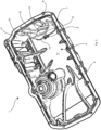
- FIG. 1 shows an oil pan 1 of an otherwise not shown internal combustion engine, in particular for a motor vehicle, also not shown.
- the oil pan 1 is designed to accommodate an oil pump 2.
- the oil pump 2 is driven by a pinion 3, which is only indicated.
- the pinion 3 is located at least partially below an oil surface 4 of an oil pan volume 5 in a proper installation position of the internal combustion engine in the motor vehicle.
- the pinion 3 is located at least in the area below the oil surface 4 within a pinion volume 6.
- the pinion volume 6 is spatially separated from the oil pan volume 5 by a partition wall 7.
- the pinion 3 can be driven by a chain drive, not shown. In doing so, it swirls up the engine oil. Due to the partition wall 7, the engine oil swirled up and foamed up by the pinion 3 cannot get into the rest of the oil pan volume 5. Without the partition wall 7, the engine oil in the oil pan volume 5 could foam up.
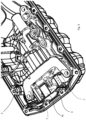
- FIG. 2 shows the oil pan 1 according to the Figure 1 without the oil pump. It can be seen that at least part of the partition wall 7 is formed integrally with the oil pan 1. In the oil pan 1 It is a part produced using a casting process, which should be produced without cast cores if possible. The oil pan 1 should be able to be removed from the casting tool. By demoldable is meant that the oil pan 1 can be removed from a casting core (not shown) after the casting process. Accordingly, the partition wall 7 with rounded bevels 14 extends orthogonally from a base surface 11 of the oil pan 1. The bevels 14 correspond to permissible casting radii. The partition wall 7 has corresponding rounded bevels 12 and easily demoldable, slightly inclined walls 13.
- the partition wall 7 extends in one piece from an inner side 10 of an outer wall 17 of the oil pan 1.
- the bevels 14 between the partition wall 7 and the inner side 10 are provided with castable or demoldable radii.
- the partition wall 7 has a recess 15 in the area of the oil drain opening 9 arranged in the oil pan 1 for draining and replacing the engine oil.
- the recess 15 is located in the middle of a vehicle vertical axis Z exactly above the oil drain opening 9.
- the partition wall continues in a shielding plate 16 arranged on the oil pump 2. Accordingly, the shielding plate 16 has an edge 22 on its side facing the partition wall 7 which ends flush with the partition wall 7.
- the shielding plate 16 is pot-shaped apart from the edge 22 and two lateral openings for driving the pinion 3.
- the shielding plate 16 has a flange area 18 on the outside, with which the shielding plate 16 can be connected to the oil pump 2.
- the shielding plate 16 has two openings in its installation position mounted with the oil pump 2, through which two strands of a drive of the pinion 3 can be guided.
- the drive is usually formed by a chain.
Landscapes
- Engineering & Computer Science (AREA)
- Mechanical Engineering (AREA)
- General Engineering & Computer Science (AREA)
- Lubrication Details And Ventilation Of Internal Combustion Engines (AREA)
Description
- Die Offenbarung betrifft eine Ölwanne. Insbesondere betrifft die Offenbarung eine Ölwanne mit einer integrierten Abschirmung des in der Ölwanne befindlichen Öls von einer Ölpumpe bzw. beweglichen Elementen der Ölpumpe.
- Das US Patent
US 9,376,942 B2 - Aus dem Stand der Technik sind ferner die
DE 10 2017 212 831 A1 , dieEP 1 526 259 A1 , dieDE 601 16 037 T2 , dieEP 1 867 862 A2 , dieEP 1 316 711 A2 und dieUS 2018/156083 A1 bekannt. - Zumindest ein Nachteil bestehender Ölwannen kann darin gesehen werden, dass Öl durch ein Antriebsritzel der Ölpumpe aufgeschäumt werden kann. Aufgeschäumtes Öl kann zum Versagen einzelner Komponenten des Verbrennungsmotors führen.
- Der Nachteil wird durch den unabhängigen Anspruch abgestellt. Die Unteransprüche bilden vorteilhafte Weiterbildungen der Offenbarung aus. Die Unteransprüche können in technologisch sinnvoller Weise miteinander kombiniert werden. Die Beschreibung, insbesondere im Zusammenhang mit den Figuren, charakterisiert und spezifiziert die Offenbarung zusätzlich.
- Vorgesehen ist demgemäß eine Ölwanne eines Verbrennungsmotors, insbesondere für ein Kraftfahrzeug, ausgestaltet zur Aufnahme einer Ölpumpe, wobei die Ölpumpe durch ein Ritzel angetrieben wird, wobei das Ritzel in einer verwendungsgemäßen Einbaulage des Verbrennungsmotors im Kraftfahrzeug zumindest teilweise unterhalb einer Öloberfläche eines Ölwannenvolumens innerhalb eines Ritzelvolumens angeordnet ist, welches durch eine Trennwand von dem Ölwannenvolumen getrennt ist, so dass von dem Ritzel aufgewirbeltes Motoröl nicht zu einem Aufschäumen von Motoröl führt, welches sich in dem Ölwannenvolumen befindet. Erfindungsgemäß ist ferner zumindest ein Teil der Trennwand einstückig an der Ölwanne angeformt und erstreckt sich die Trennwand aus einer geodätisch untenliegenden Grundfläche der Ölwanne.
- In der Ölwanne sammelt sich Motoröl. Das Motoröl wird zur Schmierung und für einen Wärmetransport innerhalb des Verbrennungsmotors verwendet und von der Ölpumpe durch Elemente des Verbrennungsmotors gepumpt. Zu den Elementen gehören Kühler, Heizungen, Filter, eine Nockenwelle, einen Nockenwellen-Verstelleinheit (Camphaser), eine Kurbelwelle und dergleichen. Das Ritzel wird häufig von einer Kette angetrieben. Das Ritzel erzeugt in dem Motoröl bedingt durch seine Rotation Entropie. Das Ritzelvolumen bezieht sich auf einen Raum, in dem das Ritzel frei rotieren kann. Durch ein Aufschlagen der Zähne des Ritzels auf der Öloberfläche wird dieses aufgeschäumt. Das aufgeschäumte Öl gelangt aufgrund der Trennwand nicht in das Ölwannenvolumen. Dadurch kann beispielsweise auch ein Öl verwendet werden, welches zumindest einen verringerten Anteil an potentiell umweltschädlichen Additiven zur Vermeidung von Schaumbildung aufweist.
- Dadurch, dass zumindest ein Teil der Trennwand einstückig an der Ölwanne angeformt ist, wird eine kostengünstige Trennwand bereitgestellt. Zusätzliche Bauteile sind gegebenenfalls nicht erforderlich.
- Dadurch, dass sich die Trennwand aus einer geodätisch untenliegenden Grundfläche der Ölwanne erstreckt, wird das Ritzelvolumen vom sonstigen Ölvolumen der Ölwanne zumindest an einer Unterseite bereichsweise abgetrennt. Die Trennwand kann in einem Urformverfahren (Druckguss- oder Sandgussverfahren) in einem Stück mit der Ölwanne hergestellt werden.
- In einer Ausgestaltung setzt sich die Trennwand in einem an der Ölpumpe angeordneten Abschirmblech fort.
- Bei dieser Ausgestaltung erstreckt sich somit die Trennwand bis zu einem Abschirmblech, das mit der Ölpumpe verbunden ist oder mit dieser verbindbar ist.
- Entsprechend einer Ausgestaltung ist zumindest das Abschirmblech topfförmig ausgestaltet und weist außenumfänglich einen Flanschbereich auf, mit welchem das Abschirmblech mit der Ölpumpe verbunden werden kann.
- Das Ritzel wird demnach weitestgehend von dem Ölwannenvolumen getrennt.
- In einer Ausgestaltung weist die Trennwand in ihrer mit der Ölpumpe montierten Einbaulage zwei Öffnungen auf, durch welche zwei Stränge eines Antriebs des Ritzels geführt werden können.
- Wie gesagt werden die Ritzel zumeist über Kettenantriebe oder Ähnliches angetrieben. Die Stränge des Antriebs verlaufen durch die besagten Öffnungen. Dadurch können notwendige Verbindungen zwischen dem Ölwannenvolumen und dem Ritzelvolumen auf ein Minimum beschränkt werden, zumal in der betriebsbereiten Einbaulage bei vorschriftsmäßiger Öleinfüllmenge die Öffnungen oberhalb von der Öloberfläche liegen.
- In einer weiteren Ausgestaltung schließt die Trennwand, das Ritzel in sich aufnehmend, bündig mit einer um die Grundfläche angeordneten Innenwand ab.
- Dadurch wird das Ritzelvolumen vom sonstigen Ölvolumen der Ölwanne zumindest an seitlichen Außenseiten bereichsweise abgetrennt.
- Erfindungsgemäß weist die Trennwand im Bereich einer in der Ölwanne angeordneten Ölablassöffnung eine Ausnehmung auf.
- Durch die Ausnehmung kann Motoröl von dem Ritzelvolumen in das Ölwannenvolumen gelangen und umgekehrt. Die Ausnehmung dient dazu, dass bei einem Ablassen des Motoröls bei einem Ölwechsel das Ritzelvolumen vollständig leerlaufen kann.
- In einer Ausgestaltung befindet sich die Ausnehmung in einer Fahrzeughochachse Z betrachtet mittig über der Ölablassöffnung.
- Dadurch kann eine Ölablassschraube, welche in die Ölablassöffnung eingeführt wird, in die Ausnehmung eindringen und diese weitestgehend verschließen. Ein gewisser Fluidaustausch zwischen dem Ritzelvolumen und dem Ölwannenvolumen ist durchaus erwünscht, damit das Öl im Ritzelvolumen im gleichen Maße altert wie das sonstige im Verbrennungsmotor befindliche Motoröl und damit es regelmäßig gefiltert und gekühlt wird. Weiterhin soll Öl bei einem Ölwechsel vollständig aus der Ölwanne und dem Ritzelvolumen auslaufen. Durch die Anordnung der
- Ölablassschraube unterhalb der Trennwand laufen beide Volumen beim Öffnen der Ölablassschraube leer.
- Zur Anordnung in einer solchen Ölwanne ist eine Ölpumpe vorgesehen, welche ein Antriebsritzel aufweist, das eine in der Ölpumpe angeordnete Fördereinheit antreibt, wobei das Ritzel ausgestaltet ist zur Aufnahme eines von einer Trennwand teilweise umschlossenen Ritzelvolumens.
- Die hierin beschriebenen Zeichnungen dienen nur zu Veranschaulichungszwecken und sollen den Umfang der vorliegenden Offenbarung in keiner Weise einschränken. Es zeigen:
-
Fig. 1 : eine Ölwanne mit einer Ölpumpe, die in einem Gehäuse untergebracht ist; -
Fig. 2 : die Ölwanne ohne die Ölpumpe; -
Fig. 3 : die Ölwanne mit einer eingebauten Ölpumpe und einer antriebsseitigen Trennwand; und -
Fig. 4 : die Ölpumpe ohne die Ölwanne mit der Trennwand, welche antriebsseitig mit einem Gehäuse der Ölpumpe verbunden ist. - Die folgende Beschreibung ist dem Wesen nach lediglich veranschaulichend. Der Klarheit halber sind in den Zeichnungen zur Bezeichnung ähnlicher Elemente dieselben Bezugszeichen verwendet.
-
Figur 1 zeigt eine Ölwanne 1 eines ansonsten nicht dargestellten Verbrennungsmotors, insbesondere für ein ebenfalls nicht dargestelltes Kraftfahrzeug. Die Ölwanne 1 ist zur Aufnahme einer Ölpumpe 2 ausgestaltet. Die Ölpumpe 2 wird durch ein nur angedeutetes Ritzel 3 angetrieben. Das Ritzel 3 befindet sich in einer verwendungsgemäßen Einbaulage des Verbrennungsmotors im Kraftfahrzeug zumindest teilweise unterhalb einer Öloberfläche 4 eines Ölwannenvolumens 5. Dabei befindet sich das Ritzel 3 zumindest im Bereich unterhalb der Öloberfläche 4 innerhalb eines Ritzelvolumens 6. Das Ritzelvolumen 6 ist räumlich durch eine Trennwand 7 von dem Ölwannenvolumen 5 getrennt. Das Ritzel 3 kann durch einen nicht dargestellten Kettentrieb angetrieben werden. Dabei wirbelt es das Motoröl auf. Aufgrund der Trennwand 7 kann das von dem Ritzel 3 aufgewirbelte und aufgeschäumte Motoröl nicht in das sonstige Ölwannenvolumen 5 gelangen. Ohne die Trennwand 7 könnte es zu einem Aufschäumen von Motoröl kommen, welches sich in dem Ölwannenvolumen 5 befindet. -
Figur 2 zeigt die Ölwanne 1 entsprechend derFigur 1 ohne die Ölpumpe. Man erkennt, dass zumindest ein Teil der Trennwand 7 einstückig an der Ölwanne 1 angeformt ist. Bei der Ölwanne 1 handelt es sich um ein in einem Gussverfahren hergestelltes Teil, das möglichst ohne umgossene Kerne hergestellt werden soll. Die Ölwanne 1 soll aus dem Gusswerkzeug entformbar sein. Mit entformbar ist gemeint, dass die Ölwanne 1 nach dem Gussvorgang aus einem nicht dargestellten Gusskern entnommen werden kann. Dementsprechend erstreckt sich die Trennwand 7 mit abgerundeten Fasen 14 orthogonal aus einer Grundfläche 11 der Ölwanne 1. Die Fasen 14 entsprechen zulässigen Gussradien. Die Trennwand 7 weist entsprechende abgerundete Fasen 12 und leicht entformbare, leicht schräggestellte Wände 13 auf. Nach dem Gussvorgang sollen weiterhin nur die notwendigsten funktionellen Flächen bearbeitet werden müssen. Vorliegend sind dies eine Dichtfläche 8 und eine Ölablassöffnung 9. Die Trennwand 7 erstreckt sich einstückig aus einer Innenseite 10 einer Außenwand 17 der Ölwanne 1. Die Fasen 14 zwischen der Trennwand 7 und der Innenseite 10 sind mit gießbaren beziehungsweise entformbaren Radien versehen. - Weiterhin ist in
Figur 2 erkennbar, dass die Trennwand 7 im Bereich der in der Ölwanne 1 angeordneten Ölablassöffnung 9 zum Ablassen und erneuern des Motoröls eine Ausnehmung 15 aufweist. Die Ausnehmung 15 befindet sich in einer Fahrzeughochachse Z betrachtet mittig genau über der Ölablassöffnung 9. Dadurch läuft beim Wechsel des Motoröls, wenn die Ölablassöffnung 9 freigegeben wird, Motoröl sowohl aus dem Ölwannenvolumen 5 als auch dem Ritzelvolumen 6 ab. - In
Figur 3 ist erkennbar, dass sich die Trennwand in einem an der Ölpumpe 2 angeordnete Abschirmblech 16 fortsetzt. Dementsprechend weist das Abschirmblech 16 an seiner der Trennwand 7 zugewandten Seite eine bündig mit der Trennwand 7 abschließende Kante 22 auf. - Das Abschirmblech 16 ist abgesehen von der Kante 22 und zwei seitlichen Öffnungen für den Antrieb des Ritzels 3 topfförmig ausgestaltet. Außenumfänglich weist das Abschirmblech 16 einen Flanschbereich 18 auf, mit welchem das Abschirmblech 16 mit der Ölpumpe 2 verbunden werden kann.
- Wie erwähnt weist das Abschirmblech 16 an seiner mit der Ölpumpe 2 montierten Einbaulage zwei Öffnungen auf, durch welche zwei Stränge eines Antriebs des Ritzels 3 geführt werden können. Der Antrieb wird üblicherweise durch eine Kette gebildet.
-
- 1
- Ölwanne
- 2
- Ölpumpe
- 3
- Ritzel
- 4
- Öloberfläche
- 5
- Ölwannenvolumen
- 6
- Ritzelvolumen
- 7
- Trennwand
- 8
- Dichtfläche
- 9
- Ölablassöffnung
- 10
- Innenseite
- 11
- Grundfläche
- 12
- Radien
- 13
- Wände
- 14
- Übergang
- 15
- Ausnehmung
- 16
- Abschirmblech
- 17
- Außenwand
- 18
- Flanschbereich
- 20
- Fördereinheit
- 22
- Kante
Claims (7)
- Ölwanne (1) eines Verbrennungsmotors, insbesondere für ein Kraftfahrzeug, ausgestaltet zur Aufnahme einer Ölpumpe (2), wobei die Ölpumpe (2) durch ein Ritzel (3) angetrieben wird, wobei das Ritzel (3) in einer verwendungsgemäßen Einbaulage des Verbrennungsmotors im Kraftfahrzeug zumindest teilweise unterhalb einer Öloberfläche (4) eines Ölwannenvolumens (5) innerhalb eines Ritzelvolumens (6) angeordnet ist, welches durch eine Trennwand (7) von dem Ölwannenvolumen (5) getrennt ist, so dass von dem Ritzel (3) aufgewirbeltes Motoröl nicht zu einem Aufschäumen von Motoröl führt, welches sich in dem Ölwannenvolumen (5) befindet, dadurch gekennzeichnet, dass die Trennwand (7) sich einstückig aus einer geodätisch untenliegenden Grundfläche (11) der Ölwanne (1) erstreckt und die an der Ölwanne (1) angeformte Trennwand (7) im Bereich einer in der Ölwanne (1) angeordneten Ölablassöffnung (9) einen Ausnehmung (15) aufweist..
- Ölwanne (1) nach Anspruch 1, wobei sich die Trennwand (7) in einem an der Ölpumpe (2) angeordneten Abschirmblech (16) fortsetzt.
- Ölwanne (1) nach Anspruch 2, wobei das Abschirmblech (16) topfförmig ausgestaltet ist und außenumfänglich einen Flanschbereich (18) aufweist, mit welchem das Abschirmblech (16) mit der Ölpumpe (2) verbunden werden kann.
- Ölwanne (1) nach einem der Ansprüche 2 bis 3, wobei das Abschirmblech (16) in seiner mit der Ölpumpe (2) montierten Einbaulage zwei Öffnungen aufweist, durch welche zwei Stränge eines Antriebs des Ritzels (3) geführt werden können.
- Ölwanne (1) nach Anspruch 1, wobei das Abschirmblech (16), das Ritzel (3) in sich aufnehmend, bündig mit der an der Ölwanne (1) angeformten Trennwand (7) abschließt.
- Ölwanne (1) nach Anspruch 1, wobei die Ausnehmung (15) sich in einer Fahrzeughochachse (Z) betrachtet mittig über der Ölablassöffnung (9) befindet.
- Ölpumpe (2), aufweisend ein Antriebsritzel (3), welches eine in der Ölpumpe (2) angeordnete Fördereinheit (20) antreibt, wobei das Ritzel (3) ausgestaltet ist in einem von einer Trennwand (7) teilweise umschlossenen Ritzelvolumen (6) nach einem der Ansprüche 1 bis 5 aufgenommen zu sein.
Applications Claiming Priority (2)
| Application Number | Priority Date | Filing Date | Title |
|---|---|---|---|
| DE102019217579.1A DE102019217579A1 (de) | 2019-11-14 | 2019-11-14 | Ölwanne mit einer integrierten Abschirmung des in der Ölwanne befindlichen Öls von einem Ritzel |
| PCT/EP2020/079456 WO2021094061A1 (de) | 2019-11-14 | 2020-10-20 | Ölwanne mit einer integrierten abschirmung des in der ölwanne befindlichen öls von einem ritzel |
Publications (2)
| Publication Number | Publication Date |
|---|---|
| EP4058660A1 EP4058660A1 (de) | 2022-09-21 |
| EP4058660B1 true EP4058660B1 (de) | 2024-11-27 |
Family
ID=72964709
Family Applications (1)
| Application Number | Title | Priority Date | Filing Date |
|---|---|---|---|
| EP20793669.1A Active EP4058660B1 (de) | 2019-11-14 | 2020-10-20 | Ölwanne mit einer integrierten abschirmung des in der ölwanne befindlichen öls von einem ritzel |
Country Status (4)
| Country | Link |
|---|---|
| EP (1) | EP4058660B1 (de) |
| CN (1) | CN114729583B (de) |
| DE (1) | DE102019217579A1 (de) |
| WO (1) | WO2021094061A1 (de) |
Families Citing this family (1)
| Publication number | Priority date | Publication date | Assignee | Title |
|---|---|---|---|---|
| CN117703562A (zh) * | 2023-12-28 | 2024-03-15 | 安徽省佳隆汽车配件有限公司 | 油底壳以及油底壳装置 |
Citations (2)
| Publication number | Priority date | Publication date | Assignee | Title |
|---|---|---|---|---|
| EP1316711B1 (de) * | 2001-12-01 | 2005-06-01 | Dr.Ing. h.c.F. Porsche Aktiengesellschaft | Brennkraftmaschine |
| EP1867862B1 (de) * | 2006-06-14 | 2010-11-03 | Bayerische Motoren Werke Aktiengesellschaft | Ölpumpenvorrichtung für eine Brennkraftmaschine mit einer Ölwanne |
Family Cites Families (13)
| Publication number | Priority date | Publication date | Assignee | Title |
|---|---|---|---|---|
| JP3052002B2 (ja) * | 1991-03-27 | 2000-06-12 | 本田技研工業株式会社 | ドライサンプ潤滑式内燃機関のオイルタンク構造 |
| GB2303669B (en) * | 1995-07-20 | 1998-03-04 | Suzuki Motor Co | Oil pump sprocket cover for an internal combustion engine |
| DE19910271B4 (de) * | 1999-03-08 | 2014-04-03 | Volkswagen Ag | Brennkraftmaschine |
| DE10029844B4 (de) * | 2000-06-16 | 2004-04-15 | Dr.Ing.H.C. F. Porsche Ag | Brennkraftmaschine, insbesondere für Motorräder |
| EP1207277B1 (de) * | 2000-11-16 | 2005-12-21 | Honda Giken Kogyo Kabushiki Kaisha | Ölpumpenstützvorrichtung für eine Brennkraftmaschine |
| JP3957674B2 (ja) * | 2003-10-21 | 2007-08-15 | 愛知機械工業株式会社 | オイルパン構造 |
| DE102008060412B4 (de) * | 2008-11-28 | 2023-03-30 | Dr. Ing. H.C. F. Porsche Aktiengesellschaft | Verbrennungsmotor |
| DE102009025453B4 (de) * | 2009-06-10 | 2019-12-05 | Dr. Ing. H.C. F. Porsche Aktiengesellschaft | Ausgleichswellenmodul |
| DE102009041981A1 (de) * | 2009-09-17 | 2011-03-24 | Daimler Ag | Behältnis |
| JP5513925B2 (ja) * | 2010-02-25 | 2014-06-04 | 本田技研工業株式会社 | クランクケース構造 |
| JP5444268B2 (ja) | 2011-02-17 | 2014-03-19 | 本田技研工業株式会社 | バッフルプレート構造体 |
| CN102748087A (zh) * | 2012-06-14 | 2012-10-24 | 东风朝阳朝柴动力有限公司 | 与发动机机体合为一体的机油泵系统 |
| KR102730528B1 (ko) * | 2016-12-06 | 2024-11-14 | 현대자동차주식회사 | 오일펌프의 조립장치 |
-
2019
- 2019-11-14 DE DE102019217579.1A patent/DE102019217579A1/de active Pending
-
2020
- 2020-10-20 EP EP20793669.1A patent/EP4058660B1/de active Active
- 2020-10-20 CN CN202080079127.0A patent/CN114729583B/zh active Active
- 2020-10-20 WO PCT/EP2020/079456 patent/WO2021094061A1/de not_active Ceased
Patent Citations (2)
| Publication number | Priority date | Publication date | Assignee | Title |
|---|---|---|---|---|
| EP1316711B1 (de) * | 2001-12-01 | 2005-06-01 | Dr.Ing. h.c.F. Porsche Aktiengesellschaft | Brennkraftmaschine |
| EP1867862B1 (de) * | 2006-06-14 | 2010-11-03 | Bayerische Motoren Werke Aktiengesellschaft | Ölpumpenvorrichtung für eine Brennkraftmaschine mit einer Ölwanne |
Also Published As
| Publication number | Publication date |
|---|---|
| EP4058660A1 (de) | 2022-09-21 |
| CN114729583B (zh) | 2025-05-02 |
| WO2021094061A1 (de) | 2021-05-20 |
| CN114729583A (zh) | 2022-07-08 |
| DE102019217579A1 (de) | 2021-05-20 |
Similar Documents
| Publication | Publication Date | Title |
|---|---|---|
| DE102008038958B4 (de) | Ölwanne mit Ölfilter an Trägereinheit | |
| DE102008060412B4 (de) | Verbrennungsmotor | |
| DE10338807B4 (de) | Entlüftungsvorrichtung für Brennkraftmaschinen | |
| DE102012215355B4 (de) | Entlüfterstruktur in einem Getriebe | |
| DE102015223566A1 (de) | Kraftfahrzeuggetriebe mit einem unterteilten Getriebegehäuse | |
| EP2686582B1 (de) | Getriebevorrichtung | |
| EP3693635B1 (de) | Antriebsstrang für ein fahrzeug, insbesondere für ein kraftfahrzeug | |
| DE102015215788A1 (de) | Ölleitschale für ein Getriebe und Getriebe | |
| EP4058660B1 (de) | Ölwanne mit einer integrierten abschirmung des in der ölwanne befindlichen öls von einem ritzel | |
| DE102004025450A1 (de) | Ölwanne für einen Motor und/oder ein Getriebe | |
| AT511074B1 (de) | Brennkraftmaschine mit zumindest einem hin- und hergehenden kolben | |
| EP1733153A2 (de) | Stirnradgetriebe | |
| EP1688595A2 (de) | Ölwanne für eine Brennkraftmaschine | |
| DE102005001863A1 (de) | Mehrzylindrige Brennkraftmaschine | |
| DE10357175B4 (de) | Bodenplatte für ein Kurbelgehäuse | |
| EP3526455B1 (de) | Ölbehälter einer brennkraftmaschine | |
| DE102008029601B4 (de) | Ausgleichswellenaufnahmestruktur | |
| DE102016101662A1 (de) | Strömungsleitung | |
| EP4409163B1 (de) | Antriebseinrichtung für ein kraftfahrzeug mit einem in einem maschinengehäuse ausgebildeten betriebsmitteltank | |
| DE102006016782B4 (de) | System umfassend ein erstes Lagerungselement zur Aufnahme einer Kurbelwelle und ein zweites Lagerungselement zur Aufnahme von mindestens zwei Getriebewellen | |
| DE19815384C2 (de) | Flüssigkeitsgekühlte Viertakt-Mehrzylinder-Brennkraftmaschine | |
| DE602006000834T2 (de) | Antriebsaggregat mit Geräuschdämpfungsvorrichtung | |
| DE102018215117B4 (de) | Antriebsvorrichtung | |
| DE102009041981A1 (de) | Behältnis | |
| DE102017130019B4 (de) | Ölwanne mit einer Filtereinrichtung und Kraftfahrzeug |
Legal Events
| Date | Code | Title | Description |
|---|---|---|---|
| STAA | Information on the status of an ep patent application or granted ep patent |
Free format text: STATUS: UNKNOWN |
|
| STAA | Information on the status of an ep patent application or granted ep patent |
Free format text: STATUS: THE INTERNATIONAL PUBLICATION HAS BEEN MADE |
|
| PUAI | Public reference made under article 153(3) epc to a published international application that has entered the european phase |
Free format text: ORIGINAL CODE: 0009012 |
|
| STAA | Information on the status of an ep patent application or granted ep patent |
Free format text: STATUS: REQUEST FOR EXAMINATION WAS MADE |
|
| 17P | Request for examination filed |
Effective date: 20220406 |
|
| AK | Designated contracting states |
Kind code of ref document: A1 Designated state(s): AL AT BE BG CH CY CZ DE DK EE ES FI FR GB GR HR HU IE IS IT LI LT LU LV MC MK MT NL NO PL PT RO RS SE SI SK SM TR |
|
| DAV | Request for validation of the european patent (deleted) | ||
| DAX | Request for extension of the european patent (deleted) | ||
| RAP3 | Party data changed (applicant data changed or rights of an application transferred) |
Owner name: STELLANTIS AUTO SAS |
|
| GRAP | Despatch of communication of intention to grant a patent |
Free format text: ORIGINAL CODE: EPIDOSNIGR1 |
|
| STAA | Information on the status of an ep patent application or granted ep patent |
Free format text: STATUS: GRANT OF PATENT IS INTENDED |
|
| INTG | Intention to grant announced |
Effective date: 20240711 |
|
| GRAS | Grant fee paid |
Free format text: ORIGINAL CODE: EPIDOSNIGR3 |
|
| GRAA | (expected) grant |
Free format text: ORIGINAL CODE: 0009210 |
|
| STAA | Information on the status of an ep patent application or granted ep patent |
Free format text: STATUS: THE PATENT HAS BEEN GRANTED |
|
| AK | Designated contracting states |
Kind code of ref document: B1 Designated state(s): AL AT BE BG CH CY CZ DE DK EE ES FI FR GB GR HR HU IE IS IT LI LT LU LV MC MK MT NL NO PL PT RO RS SE SI SK SM TR |
|
| REG | Reference to a national code |
Ref country code: GB Ref legal event code: FG4D Free format text: NOT ENGLISH |
|
| REG | Reference to a national code |
Ref country code: CH Ref legal event code: EP |
|
| REG | Reference to a national code |
Ref country code: DE Ref legal event code: R096 Ref document number: 502020009862 Country of ref document: DE |
|
| REG | Reference to a national code |
Ref country code: DE Ref legal event code: R084 Ref document number: 502020009862 Country of ref document: DE Ref country code: IE Ref legal event code: FG4D Free format text: LANGUAGE OF EP DOCUMENT: GERMAN |
|
| REG | Reference to a national code |
Ref country code: LT Ref legal event code: MG9D |
|
| REG | Reference to a national code |
Ref country code: NL Ref legal event code: MP Effective date: 20241127 |
|
| PG25 | Lapsed in a contracting state [announced via postgrant information from national office to epo] |
Ref country code: HR Free format text: LAPSE BECAUSE OF FAILURE TO SUBMIT A TRANSLATION OF THE DESCRIPTION OR TO PAY THE FEE WITHIN THE PRESCRIBED TIME-LIMIT Effective date: 20241127 Ref country code: IS Free format text: LAPSE BECAUSE OF FAILURE TO SUBMIT A TRANSLATION OF THE DESCRIPTION OR TO PAY THE FEE WITHIN THE PRESCRIBED TIME-LIMIT Effective date: 20250327 Ref country code: PT Free format text: LAPSE BECAUSE OF FAILURE TO SUBMIT A TRANSLATION OF THE DESCRIPTION OR TO PAY THE FEE WITHIN THE PRESCRIBED TIME-LIMIT Effective date: 20250327 |
|
| PG25 | Lapsed in a contracting state [announced via postgrant information from national office to epo] |
Ref country code: FI Free format text: LAPSE BECAUSE OF FAILURE TO SUBMIT A TRANSLATION OF THE DESCRIPTION OR TO PAY THE FEE WITHIN THE PRESCRIBED TIME-LIMIT Effective date: 20241127 Ref country code: NL Free format text: LAPSE BECAUSE OF FAILURE TO SUBMIT A TRANSLATION OF THE DESCRIPTION OR TO PAY THE FEE WITHIN THE PRESCRIBED TIME-LIMIT Effective date: 20241127 |
|
| PG25 | Lapsed in a contracting state [announced via postgrant information from national office to epo] |
Ref country code: BG Free format text: LAPSE BECAUSE OF FAILURE TO SUBMIT A TRANSLATION OF THE DESCRIPTION OR TO PAY THE FEE WITHIN THE PRESCRIBED TIME-LIMIT Effective date: 20241127 |
|
| PG25 | Lapsed in a contracting state [announced via postgrant information from national office to epo] |
Ref country code: ES Free format text: LAPSE BECAUSE OF FAILURE TO SUBMIT A TRANSLATION OF THE DESCRIPTION OR TO PAY THE FEE WITHIN THE PRESCRIBED TIME-LIMIT Effective date: 20241127 |
|
| PG25 | Lapsed in a contracting state [announced via postgrant information from national office to epo] |
Ref country code: NO Free format text: LAPSE BECAUSE OF FAILURE TO SUBMIT A TRANSLATION OF THE DESCRIPTION OR TO PAY THE FEE WITHIN THE PRESCRIBED TIME-LIMIT Effective date: 20250227 |
|
| PG25 | Lapsed in a contracting state [announced via postgrant information from national office to epo] |
Ref country code: LV Free format text: LAPSE BECAUSE OF FAILURE TO SUBMIT A TRANSLATION OF THE DESCRIPTION OR TO PAY THE FEE WITHIN THE PRESCRIBED TIME-LIMIT Effective date: 20241127 Ref country code: GR Free format text: LAPSE BECAUSE OF FAILURE TO SUBMIT A TRANSLATION OF THE DESCRIPTION OR TO PAY THE FEE WITHIN THE PRESCRIBED TIME-LIMIT Effective date: 20250228 |
|
| PG25 | Lapsed in a contracting state [announced via postgrant information from national office to epo] |
Ref country code: PL Free format text: LAPSE BECAUSE OF FAILURE TO SUBMIT A TRANSLATION OF THE DESCRIPTION OR TO PAY THE FEE WITHIN THE PRESCRIBED TIME-LIMIT Effective date: 20241127 |
|
| PG25 | Lapsed in a contracting state [announced via postgrant information from national office to epo] |
Ref country code: RS Free format text: LAPSE BECAUSE OF FAILURE TO SUBMIT A TRANSLATION OF THE DESCRIPTION OR TO PAY THE FEE WITHIN THE PRESCRIBED TIME-LIMIT Effective date: 20250227 |
|
| PG25 | Lapsed in a contracting state [announced via postgrant information from national office to epo] |
Ref country code: SM Free format text: LAPSE BECAUSE OF FAILURE TO SUBMIT A TRANSLATION OF THE DESCRIPTION OR TO PAY THE FEE WITHIN THE PRESCRIBED TIME-LIMIT Effective date: 20241127 |
|
| PG25 | Lapsed in a contracting state [announced via postgrant information from national office to epo] |
Ref country code: DK Free format text: LAPSE BECAUSE OF FAILURE TO SUBMIT A TRANSLATION OF THE DESCRIPTION OR TO PAY THE FEE WITHIN THE PRESCRIBED TIME-LIMIT Effective date: 20241127 |
|
| PG25 | Lapsed in a contracting state [announced via postgrant information from national office to epo] |
Ref country code: EE Free format text: LAPSE BECAUSE OF FAILURE TO SUBMIT A TRANSLATION OF THE DESCRIPTION OR TO PAY THE FEE WITHIN THE PRESCRIBED TIME-LIMIT Effective date: 20241127 |
|
| PG25 | Lapsed in a contracting state [announced via postgrant information from national office to epo] |
Ref country code: RO Free format text: LAPSE BECAUSE OF FAILURE TO SUBMIT A TRANSLATION OF THE DESCRIPTION OR TO PAY THE FEE WITHIN THE PRESCRIBED TIME-LIMIT Effective date: 20241127 |
|
| PG25 | Lapsed in a contracting state [announced via postgrant information from national office to epo] |
Ref country code: SK Free format text: LAPSE BECAUSE OF FAILURE TO SUBMIT A TRANSLATION OF THE DESCRIPTION OR TO PAY THE FEE WITHIN THE PRESCRIBED TIME-LIMIT Effective date: 20241127 |
|
| PG25 | Lapsed in a contracting state [announced via postgrant information from national office to epo] |
Ref country code: CZ Free format text: LAPSE BECAUSE OF FAILURE TO SUBMIT A TRANSLATION OF THE DESCRIPTION OR TO PAY THE FEE WITHIN THE PRESCRIBED TIME-LIMIT Effective date: 20241127 |
|
| PG25 | Lapsed in a contracting state [announced via postgrant information from national office to epo] |
Ref country code: IT Free format text: LAPSE BECAUSE OF FAILURE TO SUBMIT A TRANSLATION OF THE DESCRIPTION OR TO PAY THE FEE WITHIN THE PRESCRIBED TIME-LIMIT Effective date: 20241127 |
|
| REG | Reference to a national code |
Ref country code: DE Ref legal event code: R097 Ref document number: 502020009862 Country of ref document: DE |
|
| PG25 | Lapsed in a contracting state [announced via postgrant information from national office to epo] |
Ref country code: SE Free format text: LAPSE BECAUSE OF FAILURE TO SUBMIT A TRANSLATION OF THE DESCRIPTION OR TO PAY THE FEE WITHIN THE PRESCRIBED TIME-LIMIT Effective date: 20241127 |
|
| PLBE | No opposition filed within time limit |
Free format text: ORIGINAL CODE: 0009261 |
|
| STAA | Information on the status of an ep patent application or granted ep patent |
Free format text: STATUS: NO OPPOSITION FILED WITHIN TIME LIMIT |
|
| PGFP | Annual fee paid to national office [announced via postgrant information from national office to epo] |
Ref country code: FR Payment date: 20250924 Year of fee payment: 6 |
|
| 26N | No opposition filed |
Effective date: 20250828 |
|
| PGFP | Annual fee paid to national office [announced via postgrant information from national office to epo] |
Ref country code: DE Payment date: 20250923 Year of fee payment: 6 |