EP4058660B1 - Carter d'huile à blindage intégré de l'huile contenue à partir d'un pignon - Google Patents
Carter d'huile à blindage intégré de l'huile contenue à partir d'un pignon Download PDFInfo
- Publication number
- EP4058660B1 EP4058660B1 EP20793669.1A EP20793669A EP4058660B1 EP 4058660 B1 EP4058660 B1 EP 4058660B1 EP 20793669 A EP20793669 A EP 20793669A EP 4058660 B1 EP4058660 B1 EP 4058660B1
- Authority
- EP
- European Patent Office
- Prior art keywords
- oil
- pinion
- oil pan
- partition wall
- volume
- Prior art date
- Legal status (The legal status is an assumption and is not a legal conclusion. Google has not performed a legal analysis and makes no representation as to the accuracy of the status listed.)
- Active
Links
Images


Classifications
-
- F—MECHANICAL ENGINEERING; LIGHTING; HEATING; WEAPONS; BLASTING
- F01—MACHINES OR ENGINES IN GENERAL; ENGINE PLANTS IN GENERAL; STEAM ENGINES
- F01M—LUBRICATING OF MACHINES OR ENGINES IN GENERAL; LUBRICATING INTERNAL COMBUSTION ENGINES; CRANKCASE VENTILATING
- F01M1/00—Pressure lubrication
- F01M1/02—Pressure lubrication using lubricating pumps
-
- F—MECHANICAL ENGINEERING; LIGHTING; HEATING; WEAPONS; BLASTING
- F01—MACHINES OR ENGINES IN GENERAL; ENGINE PLANTS IN GENERAL; STEAM ENGINES
- F01M—LUBRICATING OF MACHINES OR ENGINES IN GENERAL; LUBRICATING INTERNAL COMBUSTION ENGINES; CRANKCASE VENTILATING
- F01M11/00—Component parts, details or accessories, not provided for in, or of interest apart from, groups F01M1/00 - F01M9/00
- F01M11/0004—Oilsumps
-
- F—MECHANICAL ENGINEERING; LIGHTING; HEATING; WEAPONS; BLASTING
- F01—MACHINES OR ENGINES IN GENERAL; ENGINE PLANTS IN GENERAL; STEAM ENGINES
- F01M—LUBRICATING OF MACHINES OR ENGINES IN GENERAL; LUBRICATING INTERNAL COMBUSTION ENGINES; CRANKCASE VENTILATING
- F01M1/00—Pressure lubrication
- F01M1/02—Pressure lubrication using lubricating pumps
- F01M2001/0284—Pressure lubrication using lubricating pumps mounting of the pump
-
- F—MECHANICAL ENGINEERING; LIGHTING; HEATING; WEAPONS; BLASTING
- F01—MACHINES OR ENGINES IN GENERAL; ENGINE PLANTS IN GENERAL; STEAM ENGINES
- F01M—LUBRICATING OF MACHINES OR ENGINES IN GENERAL; LUBRICATING INTERNAL COMBUSTION ENGINES; CRANKCASE VENTILATING
- F01M11/00—Component parts, details or accessories, not provided for in, or of interest apart from, groups F01M1/00 - F01M9/00
- F01M11/0004—Oilsumps
- F01M2011/005—Oilsumps with special anti-turbulence means, e.g. anti-foaming means or intermediate plates
-
- F—MECHANICAL ENGINEERING; LIGHTING; HEATING; WEAPONS; BLASTING
- F01—MACHINES OR ENGINES IN GENERAL; ENGINE PLANTS IN GENERAL; STEAM ENGINES
- F01M—LUBRICATING OF MACHINES OR ENGINES IN GENERAL; LUBRICATING INTERNAL COMBUSTION ENGINES; CRANKCASE VENTILATING
- F01M11/00—Component parts, details or accessories, not provided for in, or of interest apart from, groups F01M1/00 - F01M9/00
- F01M11/0004—Oilsumps
- F01M2011/0066—Oilsumps with passages in the wall, e.g. for axles or fluid passages
Definitions
- the disclosure relates to an oil pan.
- the disclosure relates to an oil pan with an integrated shielding of the oil in the oil pan from an oil pump or moving elements of the oil pump.
- the US patent US 9,376,942 B2 relates to a baffle plate structure in an oil pan.
- the baffle plate serves to separate an interior of the oil pan into a crankcase side and an oil chamber side.
- an oil guide member is provided.
- the oil guide member includes an inlet portion and a parallel portion.
- the inlet portion extends to a bottom surface of the oil pan.
- the inlet portion has an inlet opening for lubricant at a lower part of the inlet portion.
- the parallel portion extends from the inlet portion in a direction substantially parallel to the baffle plate to introduce the lubricant from the inlet portion to the oil pump.
- the baffle plate has an opening corresponding to the parallel portion of the strainer.
- the parallel portion of the oil guide member is arranged to close the opening in the baffle plate.
- the state of the art also includes the DE 10 2017 212 831 A1 , the EP 1 526 259 A1 , the DE 601 16 037 T2 , the EP 1 867 862 A2 , the EP 1 316 711 A2 and the US 2018/156083 A1 known.
- At least one disadvantage of existing oil pans is that oil can be foamed up by a drive pinion of the oil pump. Foamed oil can lead to the failure of individual components of the combustion engine.
- an oil pan of an internal combustion engine in particular for a motor vehicle, is provided, designed to accommodate an oil pump, wherein the oil pump is driven by a pinion is driven, wherein the pinion, in a proper installation position of the internal combustion engine in the motor vehicle, is arranged at least partially below an oil surface of an oil pan volume within a pinion volume which is separated from the oil pan volume by a partition wall, so that engine oil whirled up by the pinion does not lead to foaming of engine oil which is located in the oil pan volume.
- at least part of the partition wall is further formed integrally on the oil pan and the partition wall extends from a geodetically lower base area of the oil pan.
- Engine oil collects in the oil pan.
- the engine oil is used for lubrication and for heat transport within the internal combustion engine and is pumped by the oil pump through elements of the internal combustion engine.
- the elements include coolers, heaters, filters, a camshaft, a camshaft adjustment unit (camphaser), a crankshaft and the like.
- the pinion is often driven by a chain.
- the pinion generates entropy in the engine oil due to its rotation.
- the pinion volume refers to a space in which the pinion can rotate freely.
- the oil is foamed.
- the foamed oil does not get into the oil pan volume due to the partition. This means that, for example, an oil can be used which has at least a reduced proportion of potentially environmentally harmful additives to prevent foaming.
- the partition wall extends from a geodetically lower base area of the oil pan, the pinion volume is separated from the rest of the oil volume in the oil pan, at least on one lower side.
- the partition wall can be manufactured in one piece with the oil pan using a primary molding process (die casting or sand casting).
- the partition wall continues in a shielding plate arranged on the oil pump.
- the partition wall extends to a shielding plate which is connected to the oil pump or can be connected to it.
- At least the shielding plate is pot-shaped and has a flange area on the outside with which the shielding plate can be connected to the oil pump.
- the pinion is therefore largely separated from the oil pan volume.
- the partition wall in its installation position mounted with the oil pump, has two openings through which two strands of a pinion drive can be guided.
- the pinions are usually driven by chain drives or similar.
- the drive strands run through the openings mentioned. This means that the necessary connections between the oil pan volume and the pinion volume can be kept to a minimum, especially since the openings are above the oil surface in the operational installation position with the correct oil filling quantity.
- the partition wall which accommodates the pinion, is flush with an inner wall arranged around the base area.
- the partition wall has a recess in the region of an oil drain opening arranged in the oil pan.
- the recess allows engine oil to flow from the pinion volume into the oil pan volume and vice versa.
- the recess is designed to allow the pinion volume to drain completely when the engine oil is drained during an oil change.
- the recess is located centrally above the oil drain opening when viewed along a vehicle vertical axis Z.
- Oil drain plug below the partition wall both volumes drain when the oil drain plug is opened.
- an oil pump which has a drive pinion which drives a delivery unit arranged in the oil pump, wherein the pinion is designed to accommodate a pinion volume partially enclosed by a partition wall.
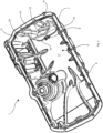
- FIG. 1 shows an oil pan 1 of an otherwise not shown internal combustion engine, in particular for a motor vehicle, also not shown.
- the oil pan 1 is designed to accommodate an oil pump 2.
- the oil pump 2 is driven by a pinion 3, which is only indicated.
- the pinion 3 is located at least partially below an oil surface 4 of an oil pan volume 5 in a proper installation position of the internal combustion engine in the motor vehicle.
- the pinion 3 is located at least in the area below the oil surface 4 within a pinion volume 6.
- the pinion volume 6 is spatially separated from the oil pan volume 5 by a partition wall 7.
- the pinion 3 can be driven by a chain drive, not shown. In doing so, it swirls up the engine oil. Due to the partition wall 7, the engine oil swirled up and foamed up by the pinion 3 cannot get into the rest of the oil pan volume 5. Without the partition wall 7, the engine oil in the oil pan volume 5 could foam up.
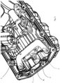
- FIG. 2 shows the oil pan 1 according to the Figure 1 without the oil pump. It can be seen that at least part of the partition wall 7 is formed integrally with the oil pan 1. In the oil pan 1 It is a part produced using a casting process, which should be produced without cast cores if possible. The oil pan 1 should be able to be removed from the casting tool. By demoldable is meant that the oil pan 1 can be removed from a casting core (not shown) after the casting process. Accordingly, the partition wall 7 with rounded bevels 14 extends orthogonally from a base surface 11 of the oil pan 1. The bevels 14 correspond to permissible casting radii. The partition wall 7 has corresponding rounded bevels 12 and easily demoldable, slightly inclined walls 13.
- the partition wall 7 extends in one piece from an inner side 10 of an outer wall 17 of the oil pan 1.
- the bevels 14 between the partition wall 7 and the inner side 10 are provided with castable or demoldable radii.
- the partition wall 7 has a recess 15 in the area of the oil drain opening 9 arranged in the oil pan 1 for draining and replacing the engine oil.
- the recess 15 is located in the middle of a vehicle vertical axis Z exactly above the oil drain opening 9.
- the partition wall continues in a shielding plate 16 arranged on the oil pump 2. Accordingly, the shielding plate 16 has an edge 22 on its side facing the partition wall 7 which ends flush with the partition wall 7.
- the shielding plate 16 is pot-shaped apart from the edge 22 and two lateral openings for driving the pinion 3.
- the shielding plate 16 has a flange area 18 on the outside, with which the shielding plate 16 can be connected to the oil pump 2.
- the shielding plate 16 has two openings in its installation position mounted with the oil pump 2, through which two strands of a drive of the pinion 3 can be guided.
- the drive is usually formed by a chain.
Landscapes
- Engineering & Computer Science (AREA)
- Mechanical Engineering (AREA)
- General Engineering & Computer Science (AREA)
- Lubrication Details And Ventilation Of Internal Combustion Engines (AREA)
Claims (7)
- Carter d'huile (1) de moteur à combustion interne, notamment pour véhicule automobile, destiné à recevoir une pompe à huile (2), la pompe à huile (2) étant entraînée par un pignon (3), le pignon (3) étant en une position d'installation selon l'utilisation du moteur à combustion interne dans le véhicule automobile est disposée au moins partiellement sous une surface d'huile (4) d'un volume de carter d'huile (5) à l'intérieur d'un volume de pignon (6) qui est séparé du carter d'huile volume (5) par une cloison (7), de sorte que l'huile moteur tourbillonnant sur le pignon (3) ne provoque pas de formation de mousse de l'huile moteur qui se trouve dans le volume du carter d'huile (5), caractérisé en ce que la cloison (7) est réalisé d'une seule pièce à partir d'une surface de base géodésiquement sous-jacente (11) du carter d'huile (1) qui s'étend et la cloison (7) formée sur le bac (1) présente un évidement (15) dans la zone de un orifice de vidange d'huile (9) disposé dans le carter d'huile (1).
- Carter d'huile (1) selon la revendication 1, dans lequel la cloison (7) se prolonge par une plaque de blindage (16) disposée sur la pompe (2).
- Carter d'huile (1) selon la revendication 2, dans lequel la plaque de blindage (16) est en forme de pot et présente une zone de bride externe (18) avec laquelle la plaque de blindage (16) peut être reliée à la pompe à huile (2).
- Carter d'huile (1) selon l'une des revendications 2 à 3, dans lequel la plaque de protection (16), dans sa position de montage montée avec la pompe à huile (2), présente deux ouvertures à travers lesquelles peuvent passer deux brins d'un entraînement du pignon (3) se laisser guider.
- Carter d'huile (1) selon la revendication 1, dans lequel la plaque de blindage (16), qui reçoit le pignon (3), affleure la cloison (7) formée sur le carter d'huile (1).
- Carter d'huile (1) selon la revendication 1, dans lequel l'évidement (15) est situé au centre au-dessus de l'ouverture de vidange d'huile (9), vu dans un axe vertical (Z) du véhicule.
- Pompe à huile (2) comportant un pignon d'entraînement (3) qui entraîne une unité de refoulement (20) disposée dans la pompe à huile (2), le pignon (3) étant conçu dans un volume de pignon (6) partiellement entouré d'une cloison (7) à inclure selon l'une des revendications 1 à 5.
Applications Claiming Priority (2)
| Application Number | Priority Date | Filing Date | Title |
|---|---|---|---|
| DE102019217579.1A DE102019217579A1 (de) | 2019-11-14 | 2019-11-14 | Ölwanne mit einer integrierten Abschirmung des in der Ölwanne befindlichen Öls von einem Ritzel |
| PCT/EP2020/079456 WO2021094061A1 (fr) | 2019-11-14 | 2020-10-20 | Carter d'huile à blindage intégré de l'huile contenue à partir d'un pignon |
Publications (2)
| Publication Number | Publication Date |
|---|---|
| EP4058660A1 EP4058660A1 (fr) | 2022-09-21 |
| EP4058660B1 true EP4058660B1 (fr) | 2024-11-27 |
Family
ID=72964709
Family Applications (1)
| Application Number | Title | Priority Date | Filing Date |
|---|---|---|---|
| EP20793669.1A Active EP4058660B1 (fr) | 2019-11-14 | 2020-10-20 | Carter d'huile à blindage intégré de l'huile contenue à partir d'un pignon |
Country Status (4)
| Country | Link |
|---|---|
| EP (1) | EP4058660B1 (fr) |
| CN (1) | CN114729583B (fr) |
| DE (1) | DE102019217579A1 (fr) |
| WO (1) | WO2021094061A1 (fr) |
Families Citing this family (1)
| Publication number | Priority date | Publication date | Assignee | Title |
|---|---|---|---|---|
| CN117703562A (zh) * | 2023-12-28 | 2024-03-15 | 安徽省佳隆汽车配件有限公司 | 油底壳以及油底壳装置 |
Citations (2)
| Publication number | Priority date | Publication date | Assignee | Title |
|---|---|---|---|---|
| EP1316711B1 (fr) * | 2001-12-01 | 2005-06-01 | Dr.Ing. h.c.F. Porsche Aktiengesellschaft | Moteur à combustion interne |
| EP1867862B1 (fr) * | 2006-06-14 | 2010-11-03 | Bayerische Motoren Werke Aktiengesellschaft | Dispositif de pompe à huile pour un moteur à combustion interne avec un carter d'huile |
Family Cites Families (13)
| Publication number | Priority date | Publication date | Assignee | Title |
|---|---|---|---|---|
| JP3052002B2 (ja) * | 1991-03-27 | 2000-06-12 | 本田技研工業株式会社 | ドライサンプ潤滑式内燃機関のオイルタンク構造 |
| GB2303669B (en) * | 1995-07-20 | 1998-03-04 | Suzuki Motor Co | Oil pump sprocket cover for an internal combustion engine |
| DE19910271B4 (de) * | 1999-03-08 | 2014-04-03 | Volkswagen Ag | Brennkraftmaschine |
| DE10029844B4 (de) * | 2000-06-16 | 2004-04-15 | Dr.Ing.H.C. F. Porsche Ag | Brennkraftmaschine, insbesondere für Motorräder |
| EP1207277B1 (fr) * | 2000-11-16 | 2005-12-21 | Honda Giken Kogyo Kabushiki Kaisha | Support de pompe à huile pour moteur à combustion |
| JP3957674B2 (ja) * | 2003-10-21 | 2007-08-15 | 愛知機械工業株式会社 | オイルパン構造 |
| DE102008060412B4 (de) * | 2008-11-28 | 2023-03-30 | Dr. Ing. H.C. F. Porsche Aktiengesellschaft | Verbrennungsmotor |
| DE102009025453B4 (de) * | 2009-06-10 | 2019-12-05 | Dr. Ing. H.C. F. Porsche Aktiengesellschaft | Ausgleichswellenmodul |
| DE102009041981A1 (de) * | 2009-09-17 | 2011-03-24 | Daimler Ag | Behältnis |
| JP5513925B2 (ja) * | 2010-02-25 | 2014-06-04 | 本田技研工業株式会社 | クランクケース構造 |
| JP5444268B2 (ja) | 2011-02-17 | 2014-03-19 | 本田技研工業株式会社 | バッフルプレート構造体 |
| CN102748087A (zh) * | 2012-06-14 | 2012-10-24 | 东风朝阳朝柴动力有限公司 | 与发动机机体合为一体的机油泵系统 |
| KR102730528B1 (ko) * | 2016-12-06 | 2024-11-14 | 현대자동차주식회사 | 오일펌프의 조립장치 |
-
2019
- 2019-11-14 DE DE102019217579.1A patent/DE102019217579A1/de active Pending
-
2020
- 2020-10-20 CN CN202080079127.0A patent/CN114729583B/zh active Active
- 2020-10-20 WO PCT/EP2020/079456 patent/WO2021094061A1/fr not_active Ceased
- 2020-10-20 EP EP20793669.1A patent/EP4058660B1/fr active Active
Patent Citations (2)
| Publication number | Priority date | Publication date | Assignee | Title |
|---|---|---|---|---|
| EP1316711B1 (fr) * | 2001-12-01 | 2005-06-01 | Dr.Ing. h.c.F. Porsche Aktiengesellschaft | Moteur à combustion interne |
| EP1867862B1 (fr) * | 2006-06-14 | 2010-11-03 | Bayerische Motoren Werke Aktiengesellschaft | Dispositif de pompe à huile pour un moteur à combustion interne avec un carter d'huile |
Also Published As
| Publication number | Publication date |
|---|---|
| CN114729583B (zh) | 2025-05-02 |
| CN114729583A (zh) | 2022-07-08 |
| DE102019217579A1 (de) | 2021-05-20 |
| EP4058660A1 (fr) | 2022-09-21 |
| WO2021094061A1 (fr) | 2021-05-20 |
Similar Documents
| Publication | Publication Date | Title |
|---|---|---|
| EP2147234B1 (fr) | Chapeau de palier, transmission, procédé et gamme de fabrication | |
| DE102008038958B4 (de) | Ölwanne mit Ölfilter an Trägereinheit | |
| DE102008060412B4 (de) | Verbrennungsmotor | |
| DE10338807B4 (de) | Entlüftungsvorrichtung für Brennkraftmaschinen | |
| DE102012215355B4 (de) | Entlüfterstruktur in einem Getriebe | |
| DE102015223566A1 (de) | Kraftfahrzeuggetriebe mit einem unterteilten Getriebegehäuse | |
| EP2686582B1 (fr) | Dispositif de transmission | |
| EP3693635B1 (fr) | Groupe motopropulseur pour un véhicule, en particulier pour un véhicule automobile | |
| DE102015215788A1 (de) | Ölleitschale für ein Getriebe und Getriebe | |
| EP4058660B1 (fr) | Carter d'huile à blindage intégré de l'huile contenue à partir d'un pignon | |
| DE102004025450A1 (de) | Ölwanne für einen Motor und/oder ein Getriebe | |
| AT511074B1 (de) | Brennkraftmaschine mit zumindest einem hin- und hergehenden kolben | |
| EP1733153A2 (fr) | Transmission par engrenage cylindrique | |
| EP1688595A2 (fr) | Carter d'huile pour moteur à combustion | |
| DE102005001863A1 (de) | Mehrzylindrige Brennkraftmaschine | |
| DE10357175B4 (de) | Bodenplatte für ein Kurbelgehäuse | |
| EP3526455B1 (fr) | Réservoir d'huile pour un moteur à combustion interne | |
| DE102008029601B4 (de) | Ausgleichswellenaufnahmestruktur | |
| DE102016101662A1 (de) | Strömungsleitung | |
| EP4409163B1 (fr) | Dispositif d'entraînement pour un véhicule automobile doté d'un réservoir de fluide de travail formé dans un carter de machine | |
| DE19815384C2 (de) | Flüssigkeitsgekühlte Viertakt-Mehrzylinder-Brennkraftmaschine | |
| DE602006000834T2 (de) | Antriebsaggregat mit Geräuschdämpfungsvorrichtung | |
| DE102018215117B4 (de) | Antriebsvorrichtung | |
| DE102009041981A1 (de) | Behältnis | |
| DE102019133472A1 (de) | Flüssigkeitswanne und Kraftfahrzeug |
Legal Events
| Date | Code | Title | Description |
|---|---|---|---|
| STAA | Information on the status of an ep patent application or granted ep patent |
Free format text: STATUS: UNKNOWN |
|
| STAA | Information on the status of an ep patent application or granted ep patent |
Free format text: STATUS: THE INTERNATIONAL PUBLICATION HAS BEEN MADE |
|
| PUAI | Public reference made under article 153(3) epc to a published international application that has entered the european phase |
Free format text: ORIGINAL CODE: 0009012 |
|
| STAA | Information on the status of an ep patent application or granted ep patent |
Free format text: STATUS: REQUEST FOR EXAMINATION WAS MADE |
|
| 17P | Request for examination filed |
Effective date: 20220406 |
|
| AK | Designated contracting states |
Kind code of ref document: A1 Designated state(s): AL AT BE BG CH CY CZ DE DK EE ES FI FR GB GR HR HU IE IS IT LI LT LU LV MC MK MT NL NO PL PT RO RS SE SI SK SM TR |
|
| DAV | Request for validation of the european patent (deleted) | ||
| DAX | Request for extension of the european patent (deleted) | ||
| RAP3 | Party data changed (applicant data changed or rights of an application transferred) |
Owner name: STELLANTIS AUTO SAS |
|
| GRAP | Despatch of communication of intention to grant a patent |
Free format text: ORIGINAL CODE: EPIDOSNIGR1 |
|
| STAA | Information on the status of an ep patent application or granted ep patent |
Free format text: STATUS: GRANT OF PATENT IS INTENDED |
|
| INTG | Intention to grant announced |
Effective date: 20240711 |
|
| GRAS | Grant fee paid |
Free format text: ORIGINAL CODE: EPIDOSNIGR3 |
|
| GRAA | (expected) grant |
Free format text: ORIGINAL CODE: 0009210 |
|
| STAA | Information on the status of an ep patent application or granted ep patent |
Free format text: STATUS: THE PATENT HAS BEEN GRANTED |
|
| AK | Designated contracting states |
Kind code of ref document: B1 Designated state(s): AL AT BE BG CH CY CZ DE DK EE ES FI FR GB GR HR HU IE IS IT LI LT LU LV MC MK MT NL NO PL PT RO RS SE SI SK SM TR |
|
| REG | Reference to a national code |
Ref country code: GB Ref legal event code: FG4D Free format text: NOT ENGLISH |
|
| REG | Reference to a national code |
Ref country code: CH Ref legal event code: EP |
|
| REG | Reference to a national code |
Ref country code: DE Ref legal event code: R096 Ref document number: 502020009862 Country of ref document: DE |
|
| REG | Reference to a national code |
Ref country code: DE Ref legal event code: R084 Ref document number: 502020009862 Country of ref document: DE Ref country code: IE Ref legal event code: FG4D Free format text: LANGUAGE OF EP DOCUMENT: GERMAN |
|
| REG | Reference to a national code |
Ref country code: LT Ref legal event code: MG9D |
|
| REG | Reference to a national code |
Ref country code: NL Ref legal event code: MP Effective date: 20241127 |
|
| PG25 | Lapsed in a contracting state [announced via postgrant information from national office to epo] |
Ref country code: HR Free format text: LAPSE BECAUSE OF FAILURE TO SUBMIT A TRANSLATION OF THE DESCRIPTION OR TO PAY THE FEE WITHIN THE PRESCRIBED TIME-LIMIT Effective date: 20241127 Ref country code: IS Free format text: LAPSE BECAUSE OF FAILURE TO SUBMIT A TRANSLATION OF THE DESCRIPTION OR TO PAY THE FEE WITHIN THE PRESCRIBED TIME-LIMIT Effective date: 20250327 Ref country code: PT Free format text: LAPSE BECAUSE OF FAILURE TO SUBMIT A TRANSLATION OF THE DESCRIPTION OR TO PAY THE FEE WITHIN THE PRESCRIBED TIME-LIMIT Effective date: 20250327 |
|
| PG25 | Lapsed in a contracting state [announced via postgrant information from national office to epo] |
Ref country code: FI Free format text: LAPSE BECAUSE OF FAILURE TO SUBMIT A TRANSLATION OF THE DESCRIPTION OR TO PAY THE FEE WITHIN THE PRESCRIBED TIME-LIMIT Effective date: 20241127 Ref country code: NL Free format text: LAPSE BECAUSE OF FAILURE TO SUBMIT A TRANSLATION OF THE DESCRIPTION OR TO PAY THE FEE WITHIN THE PRESCRIBED TIME-LIMIT Effective date: 20241127 |
|
| PG25 | Lapsed in a contracting state [announced via postgrant information from national office to epo] |
Ref country code: BG Free format text: LAPSE BECAUSE OF FAILURE TO SUBMIT A TRANSLATION OF THE DESCRIPTION OR TO PAY THE FEE WITHIN THE PRESCRIBED TIME-LIMIT Effective date: 20241127 |
|
| PG25 | Lapsed in a contracting state [announced via postgrant information from national office to epo] |
Ref country code: ES Free format text: LAPSE BECAUSE OF FAILURE TO SUBMIT A TRANSLATION OF THE DESCRIPTION OR TO PAY THE FEE WITHIN THE PRESCRIBED TIME-LIMIT Effective date: 20241127 |
|
| PG25 | Lapsed in a contracting state [announced via postgrant information from national office to epo] |
Ref country code: NO Free format text: LAPSE BECAUSE OF FAILURE TO SUBMIT A TRANSLATION OF THE DESCRIPTION OR TO PAY THE FEE WITHIN THE PRESCRIBED TIME-LIMIT Effective date: 20250227 |
|
| PG25 | Lapsed in a contracting state [announced via postgrant information from national office to epo] |
Ref country code: LV Free format text: LAPSE BECAUSE OF FAILURE TO SUBMIT A TRANSLATION OF THE DESCRIPTION OR TO PAY THE FEE WITHIN THE PRESCRIBED TIME-LIMIT Effective date: 20241127 Ref country code: GR Free format text: LAPSE BECAUSE OF FAILURE TO SUBMIT A TRANSLATION OF THE DESCRIPTION OR TO PAY THE FEE WITHIN THE PRESCRIBED TIME-LIMIT Effective date: 20250228 |
|
| PG25 | Lapsed in a contracting state [announced via postgrant information from national office to epo] |
Ref country code: PL Free format text: LAPSE BECAUSE OF FAILURE TO SUBMIT A TRANSLATION OF THE DESCRIPTION OR TO PAY THE FEE WITHIN THE PRESCRIBED TIME-LIMIT Effective date: 20241127 |
|
| PG25 | Lapsed in a contracting state [announced via postgrant information from national office to epo] |
Ref country code: RS Free format text: LAPSE BECAUSE OF FAILURE TO SUBMIT A TRANSLATION OF THE DESCRIPTION OR TO PAY THE FEE WITHIN THE PRESCRIBED TIME-LIMIT Effective date: 20250227 |
|
| PG25 | Lapsed in a contracting state [announced via postgrant information from national office to epo] |
Ref country code: SM Free format text: LAPSE BECAUSE OF FAILURE TO SUBMIT A TRANSLATION OF THE DESCRIPTION OR TO PAY THE FEE WITHIN THE PRESCRIBED TIME-LIMIT Effective date: 20241127 |
|
| PG25 | Lapsed in a contracting state [announced via postgrant information from national office to epo] |
Ref country code: DK Free format text: LAPSE BECAUSE OF FAILURE TO SUBMIT A TRANSLATION OF THE DESCRIPTION OR TO PAY THE FEE WITHIN THE PRESCRIBED TIME-LIMIT Effective date: 20241127 |
|
| PG25 | Lapsed in a contracting state [announced via postgrant information from national office to epo] |
Ref country code: EE Free format text: LAPSE BECAUSE OF FAILURE TO SUBMIT A TRANSLATION OF THE DESCRIPTION OR TO PAY THE FEE WITHIN THE PRESCRIBED TIME-LIMIT Effective date: 20241127 |
|
| PG25 | Lapsed in a contracting state [announced via postgrant information from national office to epo] |
Ref country code: RO Free format text: LAPSE BECAUSE OF FAILURE TO SUBMIT A TRANSLATION OF THE DESCRIPTION OR TO PAY THE FEE WITHIN THE PRESCRIBED TIME-LIMIT Effective date: 20241127 |
|
| PG25 | Lapsed in a contracting state [announced via postgrant information from national office to epo] |
Ref country code: SK Free format text: LAPSE BECAUSE OF FAILURE TO SUBMIT A TRANSLATION OF THE DESCRIPTION OR TO PAY THE FEE WITHIN THE PRESCRIBED TIME-LIMIT Effective date: 20241127 |
|
| PG25 | Lapsed in a contracting state [announced via postgrant information from national office to epo] |
Ref country code: CZ Free format text: LAPSE BECAUSE OF FAILURE TO SUBMIT A TRANSLATION OF THE DESCRIPTION OR TO PAY THE FEE WITHIN THE PRESCRIBED TIME-LIMIT Effective date: 20241127 |
|
| PG25 | Lapsed in a contracting state [announced via postgrant information from national office to epo] |
Ref country code: IT Free format text: LAPSE BECAUSE OF FAILURE TO SUBMIT A TRANSLATION OF THE DESCRIPTION OR TO PAY THE FEE WITHIN THE PRESCRIBED TIME-LIMIT Effective date: 20241127 |
|
| REG | Reference to a national code |
Ref country code: DE Ref legal event code: R097 Ref document number: 502020009862 Country of ref document: DE |
|
| PG25 | Lapsed in a contracting state [announced via postgrant information from national office to epo] |
Ref country code: SE Free format text: LAPSE BECAUSE OF FAILURE TO SUBMIT A TRANSLATION OF THE DESCRIPTION OR TO PAY THE FEE WITHIN THE PRESCRIBED TIME-LIMIT Effective date: 20241127 |
|
| PLBE | No opposition filed within time limit |
Free format text: ORIGINAL CODE: 0009261 |
|
| STAA | Information on the status of an ep patent application or granted ep patent |
Free format text: STATUS: NO OPPOSITION FILED WITHIN TIME LIMIT |
|
| PGFP | Annual fee paid to national office [announced via postgrant information from national office to epo] |
Ref country code: FR Payment date: 20250924 Year of fee payment: 6 |
|
| 26N | No opposition filed |
Effective date: 20250828 |
|
| PGFP | Annual fee paid to national office [announced via postgrant information from national office to epo] |
Ref country code: DE Payment date: 20250923 Year of fee payment: 6 |