EP4057434B1 - Batteriemodul, batteriepack damit und automobil - Google Patents
Batteriemodul, batteriepack damit und automobil Download PDFInfo
- Publication number
- EP4057434B1 EP4057434B1 EP21852459.3A EP21852459A EP4057434B1 EP 4057434 B1 EP4057434 B1 EP 4057434B1 EP 21852459 A EP21852459 A EP 21852459A EP 4057434 B1 EP4057434 B1 EP 4057434B1
- Authority
- EP
- European Patent Office
- Prior art keywords
- battery
- battery module
- heat
- protection plate
- present disclosure
- Prior art date
- Legal status (The legal status is an assumption and is not a legal conclusion. Google has not performed a legal analysis and makes no representation as to the accuracy of the status listed.)
- Active
Links
Images


Classifications
-
- H—ELECTRICITY
- H01—ELECTRIC ELEMENTS
- H01M—PROCESSES OR MEANS, e.g. BATTERIES, FOR THE DIRECT CONVERSION OF CHEMICAL ENERGY INTO ELECTRICAL ENERGY
- H01M50/00—Constructional details or processes of manufacture of the non-active parts of electrochemical cells other than fuel cells, e.g. hybrid cells
- H01M50/20—Mountings; Secondary casings or frames; Racks, modules or packs; Suspension devices; Shock absorbers; Transport or carrying devices; Holders
- H01M50/249—Mountings; Secondary casings or frames; Racks, modules or packs; Suspension devices; Shock absorbers; Transport or carrying devices; Holders specially adapted for aircraft or vehicles, e.g. cars or trains
-
- H—ELECTRICITY
- H01—ELECTRIC ELEMENTS
- H01M—PROCESSES OR MEANS, e.g. BATTERIES, FOR THE DIRECT CONVERSION OF CHEMICAL ENERGY INTO ELECTRICAL ENERGY
- H01M10/00—Secondary cells; Manufacture thereof
- H01M10/60—Heating or cooling; Temperature control
- H01M10/62—Heating or cooling; Temperature control specially adapted for specific applications
- H01M10/625—Vehicles
-
- H—ELECTRICITY
- H01—ELECTRIC ELEMENTS
- H01M—PROCESSES OR MEANS, e.g. BATTERIES, FOR THE DIRECT CONVERSION OF CHEMICAL ENERGY INTO ELECTRICAL ENERGY
- H01M10/00—Secondary cells; Manufacture thereof
- H01M10/60—Heating or cooling; Temperature control
- H01M10/65—Means for temperature control structurally associated with the cells
- H01M10/658—Means for temperature control structurally associated with the cells by thermal insulation or shielding
-
- H—ELECTRICITY
- H01—ELECTRIC ELEMENTS
- H01M—PROCESSES OR MEANS, e.g. BATTERIES, FOR THE DIRECT CONVERSION OF CHEMICAL ENERGY INTO ELECTRICAL ENERGY
- H01M50/00—Constructional details or processes of manufacture of the non-active parts of electrochemical cells other than fuel cells, e.g. hybrid cells
- H01M50/20—Mountings; Secondary casings or frames; Racks, modules or packs; Suspension devices; Shock absorbers; Transport or carrying devices; Holders
- H01M50/204—Racks, modules or packs for multiple batteries or multiple cells
- H01M50/207—Racks, modules or packs for multiple batteries or multiple cells characterised by their shape
- H01M50/213—Racks, modules or packs for multiple batteries or multiple cells characterised by their shape adapted for cells having curved cross-section, e.g. round or elliptic
-
- H—ELECTRICITY
- H01—ELECTRIC ELEMENTS
- H01M—PROCESSES OR MEANS, e.g. BATTERIES, FOR THE DIRECT CONVERSION OF CHEMICAL ENERGY INTO ELECTRICAL ENERGY
- H01M50/00—Constructional details or processes of manufacture of the non-active parts of electrochemical cells other than fuel cells, e.g. hybrid cells
- H01M50/20—Mountings; Secondary casings or frames; Racks, modules or packs; Suspension devices; Shock absorbers; Transport or carrying devices; Holders
- H01M50/233—Mountings; Secondary casings or frames; Racks, modules or packs; Suspension devices; Shock absorbers; Transport or carrying devices; Holders characterised by physical properties of casings or racks, e.g. dimensions
- H01M50/24—Mountings; Secondary casings or frames; Racks, modules or packs; Suspension devices; Shock absorbers; Transport or carrying devices; Holders characterised by physical properties of casings or racks, e.g. dimensions adapted for protecting batteries from their environment, e.g. from corrosion
-
- H—ELECTRICITY
- H01—ELECTRIC ELEMENTS
- H01M—PROCESSES OR MEANS, e.g. BATTERIES, FOR THE DIRECT CONVERSION OF CHEMICAL ENERGY INTO ELECTRICAL ENERGY
- H01M50/00—Constructional details or processes of manufacture of the non-active parts of electrochemical cells other than fuel cells, e.g. hybrid cells
- H01M50/20—Mountings; Secondary casings or frames; Racks, modules or packs; Suspension devices; Shock absorbers; Transport or carrying devices; Holders
- H01M50/262—Mountings; Secondary casings or frames; Racks, modules or packs; Suspension devices; Shock absorbers; Transport or carrying devices; Holders with fastening means, e.g. locks
- H01M50/264—Mountings; Secondary casings or frames; Racks, modules or packs; Suspension devices; Shock absorbers; Transport or carrying devices; Holders with fastening means, e.g. locks for cells or batteries, e.g. straps, tie rods or peripheral frames
-
- H—ELECTRICITY
- H01—ELECTRIC ELEMENTS
- H01M—PROCESSES OR MEANS, e.g. BATTERIES, FOR THE DIRECT CONVERSION OF CHEMICAL ENERGY INTO ELECTRICAL ENERGY
- H01M50/00—Constructional details or processes of manufacture of the non-active parts of electrochemical cells other than fuel cells, e.g. hybrid cells
- H01M50/20—Mountings; Secondary casings or frames; Racks, modules or packs; Suspension devices; Shock absorbers; Transport or carrying devices; Holders
- H01M50/289—Mountings; Secondary casings or frames; Racks, modules or packs; Suspension devices; Shock absorbers; Transport or carrying devices; Holders characterised by spacing elements or positioning means within frames, racks or packs
- H01M50/291—Mountings; Secondary casings or frames; Racks, modules or packs; Suspension devices; Shock absorbers; Transport or carrying devices; Holders characterised by spacing elements or positioning means within frames, racks or packs characterised by their shape
-
- H—ELECTRICITY
- H01—ELECTRIC ELEMENTS
- H01M—PROCESSES OR MEANS, e.g. BATTERIES, FOR THE DIRECT CONVERSION OF CHEMICAL ENERGY INTO ELECTRICAL ENERGY
- H01M50/00—Constructional details or processes of manufacture of the non-active parts of electrochemical cells other than fuel cells, e.g. hybrid cells
- H01M50/30—Arrangements for facilitating escape of gases
- H01M50/308—Detachable arrangements, e.g. detachable vent plugs or plug systems
-
- H—ELECTRICITY
- H01—ELECTRIC ELEMENTS
- H01M—PROCESSES OR MEANS, e.g. BATTERIES, FOR THE DIRECT CONVERSION OF CHEMICAL ENERGY INTO ELECTRICAL ENERGY
- H01M50/00—Constructional details or processes of manufacture of the non-active parts of electrochemical cells other than fuel cells, e.g. hybrid cells
- H01M50/30—Arrangements for facilitating escape of gases
- H01M50/342—Non-re-sealable arrangements
- H01M50/3425—Non-re-sealable arrangements in the form of rupturable membranes or weakened parts, e.g. pierced with the aid of a sharp member
-
- H—ELECTRICITY
- H01—ELECTRIC ELEMENTS
- H01M—PROCESSES OR MEANS, e.g. BATTERIES, FOR THE DIRECT CONVERSION OF CHEMICAL ENERGY INTO ELECTRICAL ENERGY
- H01M50/00—Constructional details or processes of manufacture of the non-active parts of electrochemical cells other than fuel cells, e.g. hybrid cells
- H01M50/30—Arrangements for facilitating escape of gases
- H01M50/35—Gas exhaust passages comprising elongated, tortuous or labyrinth-shaped exhaust passages
- H01M50/358—External gas exhaust passages located on the battery cover or case
-
- H—ELECTRICITY
- H01—ELECTRIC ELEMENTS
- H01M—PROCESSES OR MEANS, e.g. BATTERIES, FOR THE DIRECT CONVERSION OF CHEMICAL ENERGY INTO ELECTRICAL ENERGY
- H01M50/00—Constructional details or processes of manufacture of the non-active parts of electrochemical cells other than fuel cells, e.g. hybrid cells
- H01M50/50—Current conducting connections for cells or batteries
- H01M50/543—Terminals
- H01M50/547—Terminals characterised by the disposition of the terminals on the cells
- H01M50/548—Terminals characterised by the disposition of the terminals on the cells on opposite sides of the cell
-
- H—ELECTRICITY
- H01—ELECTRIC ELEMENTS
- H01M—PROCESSES OR MEANS, e.g. BATTERIES, FOR THE DIRECT CONVERSION OF CHEMICAL ENERGY INTO ELECTRICAL ENERGY
- H01M2200/00—Safety devices for primary or secondary batteries
- H01M2200/20—Pressure-sensitive devices
-
- H—ELECTRICITY
- H01—ELECTRIC ELEMENTS
- H01M—PROCESSES OR MEANS, e.g. BATTERIES, FOR THE DIRECT CONVERSION OF CHEMICAL ENERGY INTO ELECTRICAL ENERGY
- H01M2220/00—Batteries for particular applications
- H01M2220/20—Batteries in motive systems, e.g. vehicle, ship, plane
-
- Y—GENERAL TAGGING OF NEW TECHNOLOGICAL DEVELOPMENTS; GENERAL TAGGING OF CROSS-SECTIONAL TECHNOLOGIES SPANNING OVER SEVERAL SECTIONS OF THE IPC; TECHNICAL SUBJECTS COVERED BY FORMER USPC CROSS-REFERENCE ART COLLECTIONS [XRACs] AND DIGESTS
- Y02—TECHNOLOGIES OR APPLICATIONS FOR MITIGATION OR ADAPTATION AGAINST CLIMATE CHANGE
- Y02E—REDUCTION OF GREENHOUSE GAS [GHG] EMISSIONS, RELATED TO ENERGY GENERATION, TRANSMISSION OR DISTRIBUTION
- Y02E60/00—Enabling technologies; Technologies with a potential or indirect contribution to GHG emissions mitigation
- Y02E60/10—Energy storage using batteries
Definitions
- the present disclosure relates to a battery module, a battery pack comprising the same and a vehicle, and more particularly, to a battery module with enhanced stability against fire and explosion, a battery pack comprising the same and a vehicle.
- lithium secondary battery mainly uses lithium-based oxide and carbon material as a positive electrode active material and a negative electrode active material, respectively.
- this lithium secondary battery includes an electrode assembly in which a positive electrode plate and a negative electrode plate respectively coated with the positive electrode active material and the negative electrode active material are disposed with a separator interposed therebetween, and an exterior, namely a battery case, for hermetically accommodating the electrode assembly together with an electrolyte.
- lithium secondary batteries may be classified into a can-type secondary battery in which the electrode assembly is included in a metal can and a pouch-type secondary battery in which the electrode assembly is included in a pouch made of an aluminum laminate sheet.
- the large-capacity battery module includes a plurality of battery cells, and thus, when a fire or explosion occurs in some of the plurality of battery cells, flames and high-temperature gas are discharged to increase the temperature of other adjacent battery cells, which may propagate fire or thermal runaway, leading to a secondary explosion. Accordingly, there is a need for a method to increase the stability against fire or gas explosion of the battery module.
- the present disclosure is designed to solve the problems of the related art, and therefore the present disclosure is directed to providing a battery module with enhanced stability against fire and explosion, a battery pack comprising the same and a vehicle.
- a battery module comprising:
- the screen member may include a heat-resistant sheet provided in close contact with an outer surface of the cell frame to seal the exposure hole and configured such that a portion thereof facing the exposure hole is raptured by the gas pressure to open the exposure hole, and the protection plate may be located at an outer side of the heat-resistant sheet so that the heat-resistant sheet is fixed to the outer surface of the cell frame.
- the protection plate may include a rib protruding outward from an outer circumference of the communication hole.
- the protection plate may further include a perforating needle configured to perforate a part of the heat-resistant sheet when a portion of the heat-resistant sheet facing the exposure hole expands by the gas pressure.
- the heat-resistant sheet may include a rupture portion formed to have a relatively smaller sheet thickness than other portion.
- the screen member may further include an adhesive sheet attached to the protection plate to seal the communication hole and configured to be detached from the protection plate by an explosion pressure when the battery cell explodes.
- the screen member may include a heat-resistant film coated in the exposure hole to seal the exposure hole.
- the battery module may further comprise a module case having an inner space configured to accommodate the cell frame, and a staying space formed between an outer wall thereof and the cell frame spaced apart from each other to temporarily accommodate gas discharged from the battery cell and configured to communicate with the communication hole.
- a battery pack of the present disclosure includes at least one battery module.
- a vehicle of the present disclosure includes at least one battery module.
- the present disclosure since the present disclosure includes the screen member configured to seal the exposure hole and to open the exposure hole by gas pressure and the protection plate configured to fix the screen member, the gas generated inside the cell frame may be discharged to the outside through the open exposure hole and the communication hole. Since the gas discharged to the outside of the cell frame is not able to flow into other exposure holes sealed by the screen member, it is possible to effectively prevent fire or thermal runaway from propagating to other battery cells adjacent to the battery cell where the fire or thermal runaway has occurred. Accordingly, in the present disclosure, it is possible to provide a safe battery module.
- the present disclosure since the present disclosure includes the heat-resistant sheet having the rupture portion with a relatively smaller thickness, it is possible to prevent in advance the case in which, even though gas is discharged from some battery cells, the exposure hole is not opened since the heat-resistant sheet is not ruptured. Accordingly, in the present disclosure, the exposure hole may be reliably opened, thereby preventing that the discharged gas stays inside the cell frame to increase the temperature of other adjacent battery cells and thus propagate thermal runaway. Ultimately, the safety of the battery module may be effectively improved.
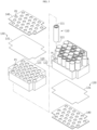
- FIG. 1 is a perspective view schematically showing a battery module according to the first embodiment of the present disclosure.
- FIG. 2 is a bottom view schematically showing the battery module according to the first embodiment of the present disclosure.
- FIG. 3 is an exploded perspective view schematically showing the battery module according to the first embodiment of the present disclosure.
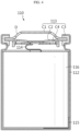
- FIG. 4 is a sectional view schematically showing a battery cell of the battery module according to the first embodiment of the present disclosure.
- the battery module 100 includes a plurality of battery cells 110, a cell frame 120, a screen member 130, and a protection plate 140.
- the battery cell 110 may include an electrode assembly 116, a battery can 112, and a cap assembly 113.
- the battery can 112 may have an empty space formed therein to accommodate the electrode assembly 116 therein.
- the battery can 112 may be configured in a cylindrical shape with an open top.
- the battery can 112 may be made of a metal material such as steel or aluminum to secure rigidity.
- the negative electrode tab may attached to the lower end of the battery can 112 so that not only a lower portion of the battery can 112 but also the battery can 112 itself may function as the negative electrode terminal 111.
- the top cap C1 may be located at an uppermost portion of the cap assembly 113 and configured to protrude upward.
- the top cap C1 may function as the positive electrode terminal 111 in the battery cell 110.
- the top cap C1 may be electrically connected to another battery cell 110 or a charging device through an external device, for example a bus bar.
- the top cap C1 may be formed of, for example, a metal material such as stainless steel or aluminum.
- the configuration of the battery cell 110 is widely known to those skilled in the art at the time of filing of this application and thus will not be described in detail here.
- the battery module 100 according to the present disclosure is not limited to the configuration of the battery cell 110 having a specific shape. That is, various types of battery cells 110 known at the time of filing of this application may be employed in the battery module 100 according to the present disclosure.
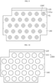
- the cell frame 120 may have an accommodation space for accommodating the plurality of battery cells 110 therein.
- the cell frame 120 may have a plurality of hollows H in a size corresponding to the battery cells 110 to accommodate the battery cells 110.
- the cell frame 120 may include a first frame 121 and a second frame 122.
- the plurality of hollows H may be formed in each of the first frame 121 and the second frame 122.
- the plurality of hollows H may have a shape extending in a vertical direction from the top to the bottom of the cell frame 120. That is, the cell frame 120 may have a plurality of exposure holes P1.
- the exposure hole P1 may be opened so that the gas discharged from the battery cell 110 moves to the outside.
- the plurality of exposure holes P1 may be formed in each of an upper portion and a lower portion of the cell frame 120.
- the exposure hole P1 may be formed at a position corresponding to the vent unit C2 of the battery cell 110.
- the exposure hole P1 may be provided at the top end of the battery cell 110. More specifically, the exposure hole P1 may be provided at a position adjacent to the opening D of the top cap C1 through which the gas discharged from the vent unit C2 is discharged to the outside of the battery can 112.
- the exposure hole P1 may be formed in a size capable of covering of the opening D of the battery can 112 entirely.
- the top cap C1 of the battery can 112 may have a ring-shaped opening D.
- the diameter of the exposure hole P1 may be configured to be greater than or equal to the diameter of the ring-shaped opening D.
- the screen member 130 may be fixed to the cell frame 120 to seal the exposure hole P1.
- an adhesive may be used so that the screen member 130 is attached to the outer surface of the cell frame 120.
- the screen member 130 may be configured such that, when gas is discharged from the vent unit C2 of the battery cell 110 to the exposure hole P1, a region thereof corresponding to the exposure hole P1 among the entire region of the screen member 130 is ruptured and opened by the gas pressure.
- the screen member 130 seals the exposure hole P1 at ordinary time, but when a gas explosion occurs in some battery cells 110 among the plurality of battery cells 110, the screen member 130 may be configured such that a region thereof corresponding to the exposure hole P1 facing the some battery cells 110 is converted from a sealed state to an open state by the gas explosion pressure.
- the protection plate 140 may be configured to fix the screen member 130.
- the protection plate 140 may be located in close contact with the outer surface of the screen member 130 so that the screen member 130 is fixed on the cell frame 120. That is, the screen member 130 is interposed between the protection plate 140 and the cell frame 120.
- the protection plate 140 may be bonded to the outer surface of the screen member 130.
- the present disclosure since the present disclosure includes the screen member 130 configured to seal the exposure hole P1 and ruptured in a region corresponding to the exposure hole P1 by gas pressure and the protection plate 140 configured to fix the screen member 130, the gas generated inside the cell frame 120 may be discharged to the outside through the open exposure hole P1 and the communication hole P2 communicating with the exposure hole P1. Since the gas discharged to the outside of the cell frame 120 is not able to flow into other exposure holes P1 sealed by the screen member 130, it is possible to effectively prevent fire or thermal runaway from propagating to other battery cells 110 adjacent to the battery cell 110 where the fire or thermal runaway has occurred. Accordingly, in the present disclosure, it is possible to provide a safe battery module 100.
- the screen member 130 may include a heat-resistant sheet 131 having a heat-resistant material.
- the heat-resistant material may be polycarbonate.
- the heat-resistant sheet 131 may be in close contact with the outer surface of the cell frame 120 to seal the exposure hole P1.
- the heat-resistant sheet 131 may have a predetermined thickness so that, when the battery cell 110 explodes, a portion thereof facing the exposure hole P1 is ruptured by the pressure of the gas discharged during the explosion.
- the thickness of the heat-resistant sheet 131 may be 0.05 mm to 0.1 mm. As a portion of the heat-resistant sheet 131 is ruptured, gas may be discharged to the outside of the cell frame 120 through the exposure hole P1.
- the present disclosure since the present disclosure includes the heat-resistant sheet 131 and the protection plate 140 for fixing the heat-resistant sheet 131, a region of the heat-resistant sheet 131 corresponding to the exposure hole P1 may be opened by the gas discharged from some battery cells 110 to effectively discharge the gas to the outside of the cell frame 120, and the battery cells 110 are not easily damaged by the flame, thereby safely protecting other battery cells 110 where thermal runaway or fire does not occur. That is, in the present disclosure, the sealed state of the exposure holes P1 of the cell frame 120 facing the remaining battery cells 110 may be continuously maintained, except for the battery cells 110 where the explosion has occurred, thereby effectively preventing secondary explosion, fire or thermal runaway from propagating.
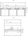
- FIG. 5 is a perspective view schematically showing some components of a battery module according to the second embodiment of the present disclosure. Also, FIG. 6 is a partially sectioned view schematically showing a part of the battery module, taken along the line C-C' of FIG. 5 .
- the module case 150 may have a staying space S formed between an outer wall 150a thereof and the cell frame 120 spaced apart from each other.
- the staying space S may communicate with the communication hole P2.
- the staying space S may be configured to temporarily accommodate the gas discharged from the battery cell 110.
- the present disclosure is configured such that the high-temperature gas discharged by the explosion of the battery cell 110 temporarily stays in the staying space S, and it is possible to prevent the gas from flowing again into the cell frame 120 through other exposure holes P1 by means of the heat-resistant sheet 131 interposed between the cell frame 120 and the protection plate 140. Accordingly, the discharged gas is not discharged to the outside of the module case 150, thereby preventing damage to a person or other devices located near the battery module 100.
- FIG. 7 is a partially sectioned view schematically showing a part of a battery module according to the third embodiment of the present disclosure.
- the battery module according to the third embodiment of the present disclosure is different from the battery module 100 according to the first embodiment of FIG. 6 , in that the protection plate 140A further includes a rib 141.
- the protection plate 140A further includes a rib 141.
- other components of the battery module according to the third embodiment of FIG. 7 are the same as those of the battery module 100 of the first embodiment of FIG. 1 and thus will not be described again.
- the protection plate 140A of the battery module 100 may include a rib 141 protruding from an outer circumference of the communication hole P2 in the outward direction (toward the outer wall 150a of the module case 150).
- the rib 141 may have a tubular shape communicating with the communication hole P2.
- the protection plate 140A fixed to the heat-resistant sheet 131 may include a rib 141 protruding upward from the outer circumference of the communication hole P2.
- the present disclosure further includes the rib 141 on the protection plate 140A, it is possible to prevent the gas discharged from some battery cells 110 among the plurality of battery cells 110 from directly flowing into the cell frame 120 through another communication hole P2 directly adjacent thereto. Accordingly, in the present disclosure, it is possible to safely protect the remaining battery cells 110 where thermal runaway or fire does not occur.
- FIG. 8 is a partially sectioned view schematically showing a part of a battery module according to the fourth embodiment of the present disclosure.
- the battery module according to the fourth embodiment of the present disclosure is different from the battery module 100 according to the first embodiment of FIG. 6 , in that a perforating needle 142 is further provided to the protection plate 140B, and other components may be the same.
- the perforating needle 142 may be provided in the communication hole P2 of the protection plate 140B.
- the perforating needle 142 may include an extending portion 142a extending from an inner surface of the communication hole P2 to a central position of the communication hole P2, and a needle portion 142b provided at an end of the extending portion 142a.
- the perforating needle 142 may be configured to come into contact with a part of the heat-resistant sheet 131 to perforate a part of the heat-resistant sheet 131.
- the needle portion 142b may have a shape sharply protruding toward the heat-resistant sheet 131 from the end of the extending portion 142a.
- the present disclosure since the present disclosure includes the perforating needle 142 configured to perforate a part of the heat-resistant sheet 131, it is possible to prevent in advance the case in which, even though gas is discharged from some battery cells 110, the exposure hole P1 is not opened since the heat-resistant sheet 131 is not ruptured. Accordingly, in the present disclosure, the exposure hole P1 may be reliably opened, thereby preventing that the discharged gas stays inside the cell frame 120 to increase the temperature of other adjacent battery cells 110 and thus propagate thermal runaway. Ultimately, the safety of the battery module 100 may be effectively improved.
- FIG. 9 is a plan view schematically showing a battery module according to the fifth embodiment of the present disclosure.
- the battery module according to the fifth embodiment of the present disclosure is different from the battery module 100 according to the first embodiment, in that the heat-resistant sheet 131 of the screen member 130C further includes a rupture portion 131a.
- Other components are the same as those of the battery module 100 according to the first embodiment and thus will not be described again.
- the heat-resistant sheet 131 of the battery module 100 may include a rupture portion 131a configured to have a smaller thickness than the remaining portion of the sheet.
- the rupture portion 131a may have a linear shape.
- the rupture portion 131a may have a cross shape in a plan view.
- the rupture portion 131a may be formed in a portion of the heat-resistant sheet 131 facing the exposure hole P1.
- the present disclosure since the present disclosure includes the heat-resistant sheet 131 having the rupture portion 131a with a relatively smaller thickness, it is possible to prevent in advance the case in which, even though gas is discharged from some battery cells 110, the exposure hole P1 is not opened since the heat-resistant sheet 131 is not ruptured. Accordingly, in the present disclosure, the exposure hole P1 may be reliably opened, thereby preventing that the discharged gas stays inside the cell frame 120 to increase the temperature of other adjacent battery cells 110 and thus propagate thermal runaway. Ultimately, the safety of the battery module 100 may be effectively improved.
- FIG. 10 is a plan view schematically showing a battery module according to the sixth embodiment of the present disclosure.
- the battery module according to the sixth embodiment of the present disclosure is different from the battery module 100 according to the first embodiment, in that the screen member 130D may further include an adhesive sheet 132.
- the adhesive sheet 132 may be provided at an outer side of the heat-resistant sheet 131. That is, the adhesive sheet 132 may be located between the heat-resistant sheet 131 and the protection plate 140 and/or between the heat-resistant sheet 131 and the cell frame 120.
- Other components are the same as those of the battery module 100 according to the first embodiment and thus will not be described again.
- the adhesive sheet 132 may be attached to the protection plate 140 to seal the communication hole P2.
- the adhesive sheet 132 may be attached to the outer circumference of the communication hole P2 by the adhesive applied to the adhesive sheet 132. That is, the adhesive sheet 132 may be located to cover the communication hole P2.
- the adhesive sheet 132 may be configured to be detached from the protection plate 140 by explosion pressure when the battery cell 110 explodes. That is, the adhesive sheet 132 may be pushed out and separated from the protection plate 140 by the pressure of the gas introduced into the exposure hole P1.
- the adhesive sheet 132 may seal the communication hole P2 at ordinary time, and when it is required to discharge gas since some battery cells 110 of the plurality of battery cells 110 explode, the adhesive sheet 132 may open the communication hole P2. Accordingly, in the present disclosure, even if gas explosion occurs in some battery cells 110, the heat-resistant sheet 131 for sealing the exposure hole P1 and the adhesive sheet 132 for sealing the communication hole P2 perform double sealing, thereby reliably preventing the gas from flowing into other adjacent battery cells 110. Ultimately, the safety of the battery module 100 may be improved.
- FIG. 11 is a plan view schematically showing a battery module according to the seventh embodiment of the present disclosure.
- the battery module according to the seventh embodiment of the present disclosure is different from the battery module 100 according to the first embodiment, in that the screen member 130E may have a different configuration. That is, the screen member 130E of the battery module according to the seventh embodiment may include a heat-resistant film 133 instead of the heat-resistant sheet 131. However, since other components are the same as those of the battery module 100 according to the first embodiment and thus will not be described again.
- the heat-resistant film 133 may be coated in the exposure hole P1 to seal the exposure hole P1. That is, the heat-resistant film 133 may be formed by filling the inside of the exposure hole P1 with a resin having heat resistance and then curing the resin.
- the heat-resistant film 133 may include, for example, polycarbonate.
- the heat-resistant film 133 may be provided in each of the plurality of exposure holes P1. In some cases, the heat-resistant film 133 may be partially interposed and fixed between the outer wall of the cell frame 120 and the protection plate 140.
- the present disclosure since the present disclosure includes the heat-resistant film 133, when compared with the heat-resistant sheet 131 of the battery module 100 of the first embodiment, the amount of the screen member 130E may be minimized, thereby reducing material costs.
- a battery pack may include at least one battery module 100 and a BMS electrically connected to the battery module 100.
- the BMS may include various types of circuits or devices to control the charge/discharge of the plurality of battery cells.
- a vehicle (not shown) may include at least one battery module 100 and a vehicle body having a receiving space in which the battery module 100 is received.
- the vehicle may be an electric vehicle, an electric scooter, an electric wheelchair or an electric bike.
Landscapes
- Chemical & Material Sciences (AREA)
- Chemical Kinetics & Catalysis (AREA)
- Electrochemistry (AREA)
- General Chemical & Material Sciences (AREA)
- Engineering & Computer Science (AREA)
- Manufacturing & Machinery (AREA)
- Aviation & Aerospace Engineering (AREA)
- Battery Mounting, Suspending (AREA)
- Sealing Battery Cases Or Jackets (AREA)
- Gas Exhaust Devices For Batteries (AREA)
- Connection Of Batteries Or Terminals (AREA)
Claims (10)
- Batteriemodul (100), welches aufweist:eine Vielzahl von Batteriezellen (110), die so konfiguriert sind, dass sie Elektrodenanschlüsse (111) aufweisen, die jeweils an ihrem einen Ende und anderen Ende ausgebildet sind, und eine Lüftungseinheit (C2) aufweisen, die geöffnet wird, um Gas zur Außenseite abzulassen, wenn ein Innendruck über einen vorbestimmten Pegel hinaus ansteigt;einen Zellrahmen (120), der so konfiguriert ist, dass er einen Aufnahmeraum zum Aufnehmen der Vielzahl von Batteriezellen (110) aufweist, wobei der Zellrahmen (120) eine Vielzahl von Expositionslöchern (P1) aufweist, die geöffnet werden, sodass sich das von der Batteriezelle (110) abgelassene Gas zur Außenseite bewegt;ein Schirmelement (130), das an dem Zellrahmen (120) befestigt ist, um das Expositionsloch (P1) zu verschließen, und konfiguriert ist, um einen dem Expositionsloch (P1) entsprechenden Bereich davon durch Gasdruck zu öffnen, wenn von der Lüftungseinheit (C2) der Batteriezelle (110) Gas abgelassen wird;eine Schutzplatte (140), die in engem Kontakt mit der Außenfläche des Schirmelements (130) angeordnet ist, wobei die Schutzplatte (140) konfiguriert ist, um das Schirmelement (130) zu fixieren, und eine Vielzahl von Verbindungslöchern (P2) aufweist, die entsprechend den Expositionslöchern (P1) angeordnet sind.
- Das Batteriemodul (100) nach Anspruch 1,wobei das Schirmelement (130) ein wärmefestes Blatt (131) aufweist, das in engem Kontakt mit einer Außenfläche des Zellrahmens (120) vorgesehen ist, und das Expositionsloch (P1) zu verschließen, und derart konfiguriert ist, dass ein zum Expositionsloch (P1) weisender Abschnitt davon durch den Gasdruck durchbrochen wird, um das Expositionsloch (P1) zu öffnen, unddie Schutzplatte (140) an einer Außenseite des wärmefesten Blatts (131) angeordnet ist, sodass das wärmefeste Blatt (131) an der Außenfläche des Zellrahmens (120) fixiert ist.
- Das Batteriemodul (100) nach Anspruch 2,
wobei die Schutzplatte (140) eine Rippe enthält, die von einem Außenumfang des Verbindungslochs (P2) auswärts vorsteht. - Das Batteriemodul (100) nach Anspruch 2,
wobei die Schutzplatte (140) ferner eine Perforationsnadel (142) enthält, die konfiguriert ist, um einen Teil des wärmefesten Blatts (131) zu perforieren, wenn sich ein zum Expositionsloch (P1) weisender Abschnitt des wärmefesten Blatts (131) durch den Gasdruck ausdehnt. - Das Batteriemodul (100) nach Anspruch 2,
wobei das wärmefeste Blatt (131) einen Bruchabschnitt (131a) enthält, der so ausgebildet ist, dass er eine relativ kleinere Blattdicke als ein anderer Abschnitt aufweist. - Das Batteriemodul (100) nach Anspruch 1,
wobei das Schirmelement (130) ferner ein Haftblatt (132) enthält, das an der Schutzplatte (140) angebracht ist, um das Verbindungsloch (P2) zu verschließen, und konfiguriert ist, um von der Schutzplatte (140) durch einen Explosionsdruck abgelöst zu werden, wenn die Batteriezelle (110) explodiert. - Das Batteriemodul (100) nach Anspruch 1,
wobei das Schirmelement (130) einen wärmefesten Film (133) enthält, der in das Expositionsloch (P1) geschichtet ist, um das Expositionsloch (P1) zu verschließen. - Das Batteriemodul (100) nach Anspruch 1, das ferner aufweist:
ein Modulgehäuse (150) mit einem Innenraum, der konfiguriert ist, um den Zellrahmen (120) aufzunehmen, und einen Verweilraum (S), der zwischen einer Außenwand davon und dem Zellrahmen (120) mit Abstand voneinander ausgebildet ist, um von der Batteriezelle (110) abgelassenes Gas zeitweilig aufzunehmen, und konfiguriert ist, um mit dem Verbindungsloch (P2) zu kommunizieren. - Batteriepack, das zumindest ein Batteriemodul (100) nach einem der Ansprüche 1 bis 8 aufweist.
- Fahrzeug, das zumindest ein Batteriemodul (100) nach einem der Ansprüche 1 bis 8 aufweist.
Applications Claiming Priority (2)
| Application Number | Priority Date | Filing Date | Title |
|---|---|---|---|
| KR20200097562 | 2020-08-04 | ||
| PCT/KR2021/010296 WO2022031056A1 (ko) | 2020-08-04 | 2021-08-04 | 배터리 모듈, 그것을 포함하는 배터리 팩, 및 자동차 |
Publications (3)
| Publication Number | Publication Date |
|---|---|
| EP4057434A1 EP4057434A1 (de) | 2022-09-14 |
| EP4057434A4 EP4057434A4 (de) | 2023-07-05 |
| EP4057434B1 true EP4057434B1 (de) | 2024-10-02 |
Family
ID=80118289
Family Applications (1)
| Application Number | Title | Priority Date | Filing Date |
|---|---|---|---|
| EP21852459.3A Active EP4057434B1 (de) | 2020-08-04 | 2021-08-04 | Batteriemodul, batteriepack damit und automobil |
Country Status (9)
| Country | Link |
|---|---|
| US (1) | US12489171B2 (de) |
| EP (1) | EP4057434B1 (de) |
| JP (1) | JP7434556B2 (de) |
| KR (1) | KR102700638B1 (de) |
| CN (1) | CN114902482B (de) |
| ES (1) | ES2993715T3 (de) |
| HU (1) | HUE068889T2 (de) |
| TW (1) | TWI890834B (de) |
| WO (1) | WO2022031056A1 (de) |
Families Citing this family (23)
| Publication number | Priority date | Publication date | Assignee | Title |
|---|---|---|---|---|
| US20230369709A1 (en) * | 2022-05-12 | 2023-11-16 | Ford Global Technologies, Llc | Battery array thermal barrier that provides a vent path and associated method of venting |
| SE546645C2 (en) * | 2022-07-13 | 2025-01-07 | Northvolt Ab | Top lid venting battery module |
| KR20240011403A (ko) * | 2022-07-19 | 2024-01-26 | 주식회사 엘지에너지솔루션 | 방폭 전지 모듈 구조 |
| KR20240021485A (ko) * | 2022-08-10 | 2024-02-19 | 주식회사 엘지에너지솔루션 | 배터리 모듈, 배터리 팩 및 자동차 |
| CN115036643B (zh) * | 2022-08-12 | 2022-12-02 | 江苏时代新能源科技有限公司 | 电池单体、电池及用电设备 |
| DE102022121801A1 (de) * | 2022-08-29 | 2024-02-29 | Bayerische Motoren Werke Aktiengesellschaft | Batterie für ein Kraftfahrzeug sowie Kraftfahrzeug |
| KR20250004793A (ko) * | 2022-11-08 | 2025-01-08 | 컨템포러리 엠퍼렉스 테크놀로지 씨오., 리미티드 | 내열 보호 부재 및 전지 |
| KR102805378B1 (ko) * | 2022-12-07 | 2025-05-12 | 삼성에스디아이 주식회사 | 이차전지 모듈 |
| US20240195004A1 (en) * | 2022-12-07 | 2024-06-13 | Samsung Sdi Co., Ltd. | Rechargeable battery module |
| WO2024219873A1 (ko) * | 2023-04-20 | 2024-10-24 | 주식회사 엘지에너지솔루션 | 배터리모듈 및 이를 포함하는 배터리팩 |
| KR20240167292A (ko) * | 2023-05-19 | 2024-11-26 | 에스케이온 주식회사 | 배터리 장치 |
| DE102023115563A1 (de) * | 2023-06-14 | 2024-12-19 | Webasto SE | Batteriegehäuse und Fahrzeugbatterie |
| DE102023117362A1 (de) * | 2023-06-30 | 2025-01-02 | Kautex Textron Gmbh & Co. Kg | Batteriegehäusekomponente für ein Batteriegehäuse, Batteriegehäuse zur Aufnahme einer Vielzahl von Batteriekomponenten und Batterie mit einem Batteriegehäuse |
| KR20250010444A (ko) * | 2023-07-12 | 2025-01-21 | 주식회사 엘지에너지솔루션 | 배터리 모듈, 이를 포함하는 배터리 팩 및 자동차 |
| CN119381614A (zh) * | 2023-07-25 | 2025-01-28 | 蔚来电池科技(安徽)有限公司 | 电池包和用电装置 |
| KR20250026001A (ko) * | 2023-08-16 | 2025-02-25 | 주식회사 엘지에너지솔루션 | 배터리 팩 |
| CN116979211B (zh) * | 2023-09-22 | 2023-12-29 | 厦门海辰储能科技股份有限公司 | 储能装置和用电设备 |
| DE102023128879A1 (de) * | 2023-10-20 | 2025-04-24 | Mercedes-Benz Group AG | Hochvoltbatterie als Traktionsbatterie für ein Kraftfahrzeug |
| CN121002714A (zh) * | 2023-12-11 | 2025-11-21 | 株式会社Lg新能源 | 电池组件、以及包括该电池组件的电池组和车辆 |
| DE102024102031A1 (de) * | 2024-01-24 | 2025-07-24 | Bayerische Motoren Werke Aktiengesellschaft | Batteriemodul für eine Traktionsbatterie eines Kraftfahrzeugs sowie Kraftfahrzeug |
| EP4606626A1 (de) * | 2024-02-22 | 2025-08-27 | Volvo Truck Corporation | Batteriemodul mit entgasungskanal |
| AT527499B1 (de) * | 2024-03-18 | 2025-03-15 | John Deere Electric Powertrain Llc | Vorrichtung zum Ableiten von Heißgas einer Batteriezelle |
| EP4641784A1 (de) * | 2024-04-26 | 2025-10-29 | Samsung SDI Co., Ltd. | Batteriesystem mit verbesserter zellabdeckung |
Family Cites Families (26)
| Publication number | Priority date | Publication date | Assignee | Title |
|---|---|---|---|---|
| JPH06111798A (ja) | 1992-09-02 | 1994-04-22 | Globe Union Inc | 爆発減衰システム及び該システムを蓄電池に組込む方法 |
| EP1581956A2 (de) | 2003-01-04 | 2005-10-05 | 3M Innovative Properties Company | Fahrzeugbatteriepackisolator |
| JP2008270032A (ja) | 2007-04-23 | 2008-11-06 | Toshiba Corp | 二次電池モジュール |
| JP4815026B2 (ja) | 2009-07-17 | 2011-11-16 | パナソニック株式会社 | 電池モジュールとそれを用いた電池パック |
| US8518569B2 (en) * | 2010-03-01 | 2013-08-27 | Apple Inc. | Integrated frame battery cell |
| KR20130043154A (ko) | 2010-08-06 | 2013-04-29 | 파나소닉 주식회사 | 전지 모듈 |
| JP5803553B2 (ja) | 2011-10-14 | 2015-11-04 | 日産自動車株式会社 | 密閉型電池の排気栓 |
| JP5461610B2 (ja) * | 2012-03-22 | 2014-04-02 | 三菱重工業株式会社 | 電池及び電池システム |
| KR101605936B1 (ko) | 2013-05-02 | 2016-03-23 | 주식회사 엘지화학 | 파우치형 배터리 셀 내부의 가스 배출이 가능한 배터리 팩 |
| CN105849933B (zh) * | 2013-08-30 | 2019-06-18 | 睿能创意公司 | 带有热逸溃减缓的便携式电能储存器件 |
| JP6283964B2 (ja) * | 2014-02-07 | 2018-02-28 | パナソニックIpマネジメント株式会社 | 電池モジュール |
| US10008704B2 (en) | 2014-07-25 | 2018-06-26 | Faster Faster Inc. | Thermal shield for preventing thermal runaway in a battery assembly |
| KR101757527B1 (ko) | 2015-04-02 | 2017-07-13 | 재단법인 한국탄소융합기술원 | 이중 케이스 내에 배치된 가스 투과막을 갖는 전기화학적 에너지 저장장치 |
| US20180138478A1 (en) * | 2016-11-14 | 2018-05-17 | Anhui Xinen Technology Co., Ltd. | Alleviating explosion propagation in a battery module |
| KR102178786B1 (ko) * | 2017-03-03 | 2020-11-13 | 주식회사 엘지화학 | 카트리지 및 이를 포함하는 배터리 모듈 |
| WO2019010442A1 (en) * | 2017-07-07 | 2019-01-10 | Johnson Controls Technology Company | LITHIUM-ION CELL PERFORATION DEGASSING |
| KR102258179B1 (ko) | 2017-08-30 | 2021-05-28 | 주식회사 엘지에너지솔루션 | 원통형 이차전지 모듈 |
| KR102444124B1 (ko) | 2017-10-16 | 2022-09-16 | 주식회사 엘지에너지솔루션 | 배터리 모듈 및 이를 포함하는 배터리 팩 |
| CN107994181B (zh) | 2017-10-30 | 2020-11-13 | 吉利汽车研究院(宁波)有限公司 | 一种动力电池平衡防爆装置 |
| JP7010671B2 (ja) | 2017-11-15 | 2022-01-26 | スカッドエレクトロニクスジャパン株式会社 | リチウムイオン電池モジュール |
| KR102152886B1 (ko) * | 2017-12-11 | 2020-09-07 | 삼성에스디아이 주식회사 | 배터리 팩 |
| KR102353917B1 (ko) | 2018-01-04 | 2022-01-19 | 주식회사 엘지에너지솔루션 | 열전도 패드를 구비한 배터리 모듈 |
| US10828076B2 (en) | 2018-05-17 | 2020-11-10 | Biedermann Technologies Gmbh & Co. Kg | Bone fixation assembly with enlarged angle of inclination for a bone anchor to a favored side |
| CN208507892U (zh) | 2018-08-09 | 2019-02-15 | 西安优必惠电子科技有限公司 | 一种新能源汽车用电池散热装置 |
| US12244025B2 (en) * | 2018-12-29 | 2025-03-04 | Contemporary Amperex Technology (Hong Kong) Limited | Secondary battery and battery module |
| KR20200097562A (ko) | 2019-02-08 | 2020-08-19 | 주식회사 오가넬 | 미세조류를 포함하는 과일 및 채소 신선도 유지제 및 이를 이용한 채소 또는 과일의 신선도를 유지하는 방법 |
-
2021
- 2021-08-04 US US17/787,877 patent/US12489171B2/en active Active
- 2021-08-04 HU HUE21852459A patent/HUE068889T2/hu unknown
- 2021-08-04 KR KR1020210102795A patent/KR102700638B1/ko active Active
- 2021-08-04 EP EP21852459.3A patent/EP4057434B1/de active Active
- 2021-08-04 ES ES21852459T patent/ES2993715T3/es active Active
- 2021-08-04 TW TW110128721A patent/TWI890834B/zh active
- 2021-08-04 JP JP2022534443A patent/JP7434556B2/ja active Active
- 2021-08-04 WO PCT/KR2021/010296 patent/WO2022031056A1/ko not_active Ceased
- 2021-08-04 CN CN202180007967.0A patent/CN114902482B/zh active Active
Also Published As
| Publication number | Publication date |
|---|---|
| JP7434556B2 (ja) | 2024-02-20 |
| JP2023505972A (ja) | 2023-02-14 |
| KR20220017383A (ko) | 2022-02-11 |
| TW202215698A (zh) | 2022-04-16 |
| KR102700638B1 (ko) | 2024-08-29 |
| ES2993715T3 (en) | 2025-01-07 |
| TWI890834B (zh) | 2025-07-21 |
| EP4057434A1 (de) | 2022-09-14 |
| HUE068889T2 (hu) | 2025-02-28 |
| WO2022031056A1 (ko) | 2022-02-10 |
| CN114902482A (zh) | 2022-08-12 |
| US12489171B2 (en) | 2025-12-02 |
| CN114902482B (zh) | 2024-12-06 |
| EP4057434A4 (de) | 2023-07-05 |
| US20230021740A1 (en) | 2023-01-26 |
Similar Documents
| Publication | Publication Date | Title |
|---|---|---|
| EP4057434B1 (de) | Batteriemodul, batteriepack damit und automobil | |
| EP3525256B1 (de) | Batteriemodul und batteriepack mit erhöhter sicherheit | |
| EP4207461A1 (de) | Batteriepack und automobil damit | |
| KR102080903B1 (ko) | 전극 리드 및 이를 포함하는 이차 전지 | |
| EP4191760B1 (de) | Sekundärbatterie | |
| US20240234930A9 (en) | Battery module and battery pack including the same | |
| KR20140091222A (ko) | 파우치형 이차 전지 및 이를 포함하는 배터리 팩 | |
| US12456779B2 (en) | Battery module, battery pack, and vehicle | |
| EP2846378B1 (de) | Wiederaufladbare Batterie mit einer Sicherung | |
| EP4167363B1 (de) | Batteriemodul, batteriepack und fahrzeug damit | |
| KR20230049453A (ko) | 이차 전지 및 이를 포함하는 전지 모듈 | |
| EP4576375A1 (de) | Batteriepack und energiespeichersystem damit | |
| KR101986196B1 (ko) | 배터리 모듈 | |
| KR101114781B1 (ko) | 이차 전지의 화성 처리층을 이용한 안전 장치 | |
| EP4113734A1 (de) | Beutelartige sekundärbatterie mit verbesserter sicherheit und batteriemodul damit | |
| CA3246376A1 (en) | REINFORCED SAFETY BATTERY MODULE | |
| CN120693732A (zh) | 电池组件 |
Legal Events
| Date | Code | Title | Description |
|---|---|---|---|
| STAA | Information on the status of an ep patent application or granted ep patent |
Free format text: STATUS: THE INTERNATIONAL PUBLICATION HAS BEEN MADE |
|
| PUAI | Public reference made under article 153(3) epc to a published international application that has entered the european phase |
Free format text: ORIGINAL CODE: 0009012 |
|
| STAA | Information on the status of an ep patent application or granted ep patent |
Free format text: STATUS: REQUEST FOR EXAMINATION WAS MADE |
|
| 17P | Request for examination filed |
Effective date: 20220610 |
|
| AK | Designated contracting states |
Kind code of ref document: A1 Designated state(s): AL AT BE BG CH CY CZ DE DK EE ES FI FR GB GR HR HU IE IS IT LI LT LU LV MC MK MT NL NO PL PT RO RS SE SI SK SM TR |
|
| A4 | Supplementary search report drawn up and despatched |
Effective date: 20230607 |
|
| RIC1 | Information provided on ipc code assigned before grant |
Ipc: H01M 50/548 20210101ALI20230601BHEP Ipc: H01M 50/358 20210101ALI20230601BHEP Ipc: H01M 50/264 20210101ALI20230601BHEP Ipc: H01M 50/291 20210101ALI20230601BHEP Ipc: H01M 10/658 20140101ALI20230601BHEP Ipc: H01M 50/20 20210101ALI20230601BHEP Ipc: H01M 50/24 20210101ALI20230601BHEP Ipc: H01M 50/308 20210101ALI20230601BHEP Ipc: H01M 50/342 20210101AFI20230601BHEP |
|
| DAV | Request for validation of the european patent (deleted) | ||
| DAX | Request for extension of the european patent (deleted) | ||
| GRAP | Despatch of communication of intention to grant a patent |
Free format text: ORIGINAL CODE: EPIDOSNIGR1 |
|
| STAA | Information on the status of an ep patent application or granted ep patent |
Free format text: STATUS: GRANT OF PATENT IS INTENDED |
|
| INTG | Intention to grant announced |
Effective date: 20240529 |
|
| GRAS | Grant fee paid |
Free format text: ORIGINAL CODE: EPIDOSNIGR3 |
|
| P01 | Opt-out of the competence of the unified patent court (upc) registered |
Free format text: CASE NUMBER: APP_33845/2024 Effective date: 20240606 |
|
| GRAA | (expected) grant |
Free format text: ORIGINAL CODE: 0009210 |
|
| STAA | Information on the status of an ep patent application or granted ep patent |
Free format text: STATUS: THE PATENT HAS BEEN GRANTED |
|
| AK | Designated contracting states |
Kind code of ref document: B1 Designated state(s): AL AT BE BG CH CY CZ DE DK EE ES FI FR GB GR HR HU IE IS IT LI LT LU LV MC MK MT NL NO PL PT RO RS SE SI SK SM TR |
|
| REG | Reference to a national code |
Ref country code: GB Ref legal event code: FG4D |
|
| REG | Reference to a national code |
Ref country code: CH Ref legal event code: EP |
|
| REG | Reference to a national code |
Ref country code: IE Ref legal event code: FG4D |
|
| REG | Reference to a national code |
Ref country code: DE Ref legal event code: R096 Ref document number: 602021019723 Country of ref document: DE |
|
| REG | Reference to a national code |
Ref country code: ES Ref legal event code: FG2A Ref document number: 2993715 Country of ref document: ES Kind code of ref document: T3 Effective date: 20250107 |
|
| REG | Reference to a national code |
Ref country code: LT Ref legal event code: MG9D |
|
| REG | Reference to a national code |
Ref country code: NL Ref legal event code: MP Effective date: 20241002 |
|
| REG | Reference to a national code |
Ref country code: HU Ref legal event code: AG4A Ref document number: E068889 Country of ref document: HU |
|
| REG | Reference to a national code |
Ref country code: AT Ref legal event code: MK05 Ref document number: 1729131 Country of ref document: AT Kind code of ref document: T Effective date: 20241002 |
|
| PG25 | Lapsed in a contracting state [announced via postgrant information from national office to epo] |
Ref country code: NL Free format text: LAPSE BECAUSE OF FAILURE TO SUBMIT A TRANSLATION OF THE DESCRIPTION OR TO PAY THE FEE WITHIN THE PRESCRIBED TIME-LIMIT Effective date: 20241002 |
|
| PG25 | Lapsed in a contracting state [announced via postgrant information from national office to epo] |
Ref country code: NL Free format text: LAPSE BECAUSE OF FAILURE TO SUBMIT A TRANSLATION OF THE DESCRIPTION OR TO PAY THE FEE WITHIN THE PRESCRIBED TIME-LIMIT Effective date: 20241002 |
|
| PG25 | Lapsed in a contracting state [announced via postgrant information from national office to epo] |
Ref country code: HR Free format text: LAPSE BECAUSE OF FAILURE TO SUBMIT A TRANSLATION OF THE DESCRIPTION OR TO PAY THE FEE WITHIN THE PRESCRIBED TIME-LIMIT Effective date: 20241002 Ref country code: IS Free format text: LAPSE BECAUSE OF FAILURE TO SUBMIT A TRANSLATION OF THE DESCRIPTION OR TO PAY THE FEE WITHIN THE PRESCRIBED TIME-LIMIT Effective date: 20250202 Ref country code: PT Free format text: LAPSE BECAUSE OF FAILURE TO SUBMIT A TRANSLATION OF THE DESCRIPTION OR TO PAY THE FEE WITHIN THE PRESCRIBED TIME-LIMIT Effective date: 20250203 |
|
| PG25 | Lapsed in a contracting state [announced via postgrant information from national office to epo] |
Ref country code: FI Free format text: LAPSE BECAUSE OF FAILURE TO SUBMIT A TRANSLATION OF THE DESCRIPTION OR TO PAY THE FEE WITHIN THE PRESCRIBED TIME-LIMIT Effective date: 20241002 |
|
| PG25 | Lapsed in a contracting state [announced via postgrant information from national office to epo] |
Ref country code: BG Free format text: LAPSE BECAUSE OF FAILURE TO SUBMIT A TRANSLATION OF THE DESCRIPTION OR TO PAY THE FEE WITHIN THE PRESCRIBED TIME-LIMIT Effective date: 20241002 |
|
| PG25 | Lapsed in a contracting state [announced via postgrant information from national office to epo] |
Ref country code: NO Free format text: LAPSE BECAUSE OF FAILURE TO SUBMIT A TRANSLATION OF THE DESCRIPTION OR TO PAY THE FEE WITHIN THE PRESCRIBED TIME-LIMIT Effective date: 20250102 |
|
| PG25 | Lapsed in a contracting state [announced via postgrant information from national office to epo] |
Ref country code: AT Free format text: LAPSE BECAUSE OF FAILURE TO SUBMIT A TRANSLATION OF THE DESCRIPTION OR TO PAY THE FEE WITHIN THE PRESCRIBED TIME-LIMIT Effective date: 20241002 Ref country code: LV Free format text: LAPSE BECAUSE OF FAILURE TO SUBMIT A TRANSLATION OF THE DESCRIPTION OR TO PAY THE FEE WITHIN THE PRESCRIBED TIME-LIMIT Effective date: 20241002 Ref country code: GR Free format text: LAPSE BECAUSE OF FAILURE TO SUBMIT A TRANSLATION OF THE DESCRIPTION OR TO PAY THE FEE WITHIN THE PRESCRIBED TIME-LIMIT Effective date: 20250103 |
|
| PG25 | Lapsed in a contracting state [announced via postgrant information from national office to epo] |
Ref country code: PL Free format text: LAPSE BECAUSE OF FAILURE TO SUBMIT A TRANSLATION OF THE DESCRIPTION OR TO PAY THE FEE WITHIN THE PRESCRIBED TIME-LIMIT Effective date: 20241002 Ref country code: CZ Free format text: LAPSE BECAUSE OF FAILURE TO SUBMIT A TRANSLATION OF THE DESCRIPTION OR TO PAY THE FEE WITHIN THE PRESCRIBED TIME-LIMIT Effective date: 20241002 |
|
| PG25 | Lapsed in a contracting state [announced via postgrant information from national office to epo] |
Ref country code: RS Free format text: LAPSE BECAUSE OF FAILURE TO SUBMIT A TRANSLATION OF THE DESCRIPTION OR TO PAY THE FEE WITHIN THE PRESCRIBED TIME-LIMIT Effective date: 20250102 |
|
| PG25 | Lapsed in a contracting state [announced via postgrant information from national office to epo] |
Ref country code: SM Free format text: LAPSE BECAUSE OF FAILURE TO SUBMIT A TRANSLATION OF THE DESCRIPTION OR TO PAY THE FEE WITHIN THE PRESCRIBED TIME-LIMIT Effective date: 20241002 |
|
| REG | Reference to a national code |
Ref country code: DE Ref legal event code: R097 Ref document number: 602021019723 Country of ref document: DE |
|
| PG25 | Lapsed in a contracting state [announced via postgrant information from national office to epo] |
Ref country code: DK Free format text: LAPSE BECAUSE OF FAILURE TO SUBMIT A TRANSLATION OF THE DESCRIPTION OR TO PAY THE FEE WITHIN THE PRESCRIBED TIME-LIMIT Effective date: 20241002 |
|
| PGFP | Annual fee paid to national office [announced via postgrant information from national office to epo] |
Ref country code: BE Payment date: 20250407 Year of fee payment: 5 |
|
| PG25 | Lapsed in a contracting state [announced via postgrant information from national office to epo] |
Ref country code: EE Free format text: LAPSE BECAUSE OF FAILURE TO SUBMIT A TRANSLATION OF THE DESCRIPTION OR TO PAY THE FEE WITHIN THE PRESCRIBED TIME-LIMIT Effective date: 20241002 |
|
| PG25 | Lapsed in a contracting state [announced via postgrant information from national office to epo] |
Ref country code: RO Free format text: LAPSE BECAUSE OF FAILURE TO SUBMIT A TRANSLATION OF THE DESCRIPTION OR TO PAY THE FEE WITHIN THE PRESCRIBED TIME-LIMIT Effective date: 20241002 |
|
| PG25 | Lapsed in a contracting state [announced via postgrant information from national office to epo] |
Ref country code: SK Free format text: LAPSE BECAUSE OF FAILURE TO SUBMIT A TRANSLATION OF THE DESCRIPTION OR TO PAY THE FEE WITHIN THE PRESCRIBED TIME-LIMIT Effective date: 20241002 |
|
| PG25 | Lapsed in a contracting state [announced via postgrant information from national office to epo] |
Ref country code: IT Free format text: LAPSE BECAUSE OF FAILURE TO SUBMIT A TRANSLATION OF THE DESCRIPTION OR TO PAY THE FEE WITHIN THE PRESCRIBED TIME-LIMIT Effective date: 20241002 |
|
| PLBE | No opposition filed within time limit |
Free format text: ORIGINAL CODE: 0009261 |
|
| STAA | Information on the status of an ep patent application or granted ep patent |
Free format text: STATUS: NO OPPOSITION FILED WITHIN TIME LIMIT |
|
| PG25 | Lapsed in a contracting state [announced via postgrant information from national office to epo] |
Ref country code: SE Free format text: LAPSE BECAUSE OF FAILURE TO SUBMIT A TRANSLATION OF THE DESCRIPTION OR TO PAY THE FEE WITHIN THE PRESCRIBED TIME-LIMIT Effective date: 20241002 |
|
| 26N | No opposition filed |
Effective date: 20250703 |
|
| PGFP | Annual fee paid to national office [announced via postgrant information from national office to epo] |
Ref country code: HU Payment date: 20250827 Year of fee payment: 5 |
|
| PGFP | Annual fee paid to national office [announced via postgrant information from national office to epo] |
Ref country code: ES Payment date: 20250911 Year of fee payment: 5 |
|
| PGFP | Annual fee paid to national office [announced via postgrant information from national office to epo] |
Ref country code: DE Payment date: 20250721 Year of fee payment: 5 |
|
| PGFP | Annual fee paid to national office [announced via postgrant information from national office to epo] |
Ref country code: GB Payment date: 20250722 Year of fee payment: 5 |
|
| PGFP | Annual fee paid to national office [announced via postgrant information from national office to epo] |
Ref country code: FR Payment date: 20250725 Year of fee payment: 5 |