EP4057307A1 - Reactor - Google Patents
Reactor Download PDFInfo
- Publication number
- EP4057307A1 EP4057307A1 EP21209181.3A EP21209181A EP4057307A1 EP 4057307 A1 EP4057307 A1 EP 4057307A1 EP 21209181 A EP21209181 A EP 21209181A EP 4057307 A1 EP4057307 A1 EP 4057307A1
- Authority
- EP
- European Patent Office
- Prior art keywords
- air
- magnetic
- core coil
- magnetic sensor
- reactor
- Prior art date
- Legal status (The legal status is an assumption and is not a legal conclusion. Google has not performed a legal analysis and makes no representation as to the accuracy of the status listed.)
- Withdrawn
Links
Images



Classifications
-
- H—ELECTRICITY
- H01—ELECTRIC ELEMENTS
- H01F—MAGNETS; INDUCTANCES; TRANSFORMERS; SELECTION OF MATERIALS FOR THEIR MAGNETIC PROPERTIES
- H01F27/00—Details of transformers or inductances, in general
- H01F27/40—Structural association with built-in electric component, e.g. fuse
- H01F27/402—Association of measuring or protective means
-
- H—ELECTRICITY
- H01—ELECTRIC ELEMENTS
- H01F—MAGNETS; INDUCTANCES; TRANSFORMERS; SELECTION OF MATERIALS FOR THEIR MAGNETIC PROPERTIES
- H01F27/00—Details of transformers or inductances, in general
- H01F27/34—Special means for preventing or reducing unwanted electric or magnetic effects, e.g. no-load losses, reactive currents, harmonics, oscillations, leakage fields
-
- H—ELECTRICITY
- H01—ELECTRIC ELEMENTS
- H01F—MAGNETS; INDUCTANCES; TRANSFORMERS; SELECTION OF MATERIALS FOR THEIR MAGNETIC PROPERTIES
- H01F27/00—Details of transformers or inductances, in general
- H01F27/08—Cooling; Ventilating
-
- H—ELECTRICITY
- H01—ELECTRIC ELEMENTS
- H01F—MAGNETS; INDUCTANCES; TRANSFORMERS; SELECTION OF MATERIALS FOR THEIR MAGNETIC PROPERTIES
- H01F27/00—Details of transformers or inductances, in general
- H01F27/28—Coils; Windings; Conductive connections
-
- H—ELECTRICITY
- H01—ELECTRIC ELEMENTS
- H01F—MAGNETS; INDUCTANCES; TRANSFORMERS; SELECTION OF MATERIALS FOR THEIR MAGNETIC PROPERTIES
- H01F37/00—Fixed inductances not covered by group H01F17/00
- H01F37/005—Fixed inductances not covered by group H01F17/00 without magnetic core
-
- H—ELECTRICITY
- H01—ELECTRIC ELEMENTS
- H01F—MAGNETS; INDUCTANCES; TRANSFORMERS; SELECTION OF MATERIALS FOR THEIR MAGNETIC PROPERTIES
- H01F27/00—Details of transformers or inductances, in general
- H01F27/34—Special means for preventing or reducing unwanted electric or magnetic effects, e.g. no-load losses, reactive currents, harmonics, oscillations, leakage fields
- H01F2027/348—Preventing eddy currents
Definitions
- the present disclosure relates to a reactor including a magnetic sensor formed by conductive members.
- Reactors are used in various applications such as office automation apparatuses, solar power generation systems, automobiles, etc.
- the reactor includes a coil and a magnetic body arranged on both end surfaces which are orthogonal to the winding axial direction of the coil.
- the coil is electrically connected to external devices, and generates magnetic flux when electric power is supplied from the external devices.
- the magnetic body becomes a magnetic path through which the magnetic flux generated by the coil passes. Accordingly, the reactor is an electromagnetic component that converts electric energy into magnetic energy, and stores and releases said energy.
- the reactor may include a magnetic sensor formed by winding conductive members to detect magnetic field.
- the magnetic sensor is arranged to face the end surface orthogonal to the winding axial direction of the coil and between the coil and the magnetic body. That is, the magnetic sensor is arranged in the extended region of the inner circumferential surface that is the hollow portion of the coil.
- An air-core coil may be used as the coil.
- the magnetic body When the magnetic body is inserted in the inner circumference of the coil, since the magnetic body becomes the magnetic path, the magnetic flux is unlikely to hit the end surface of the conductive member forming the magnetic sensor, except for the leakage flux.
- the air-core coil when used, the magnetic flux generated from the air-core coil expands in the boundary between the air-core coil and the magnetic body, and the amount of the magnetic flux hitting the end surface of the conductive member forming the magnetic sensor is large in comparison with a case in which the magnetic body is inserted in the inner circumference of the coil.
- the magnetic flux generated by the air-core coil 101 flows toward the magnetic body 102 (an arrow in Fig. 11 indicates the flow of the magnetic flux). Accordingly, the magnetic flux expands from the end portion of the air-core coil toward the magnetic body 102 (a portion circled by a dashed line in Fig. 11 ), the leakage flux does not pass through the inner circumference of the magnetic sensor 103 and may hit the end surface of the magnetic sensor 103. Similarly, the magnetic flux flowing through the magnetic body 102 may flow toward the air-core coil 101 and may hit the end surface of the magnetic sensor 103.
- the magnetic sensor When the magnetic flux hits the end surface of the magnetic sensor, eddy current loss is produced in the magnetic sensor. Therefore, as the amount of the magnetic flux hitting the end surface of the magnetic sensor increases, eddy current loss also increases. Accordingly, the magnetic sensor generates heat in proportion to the increase in eddy current loss, and as a result, the amount of heat generated by the reactor also increases.
- the present disclosure has been made to address the above described problem, and the objective is to provide a reactor that can suppress magnetic flux from hitting the end surfaces of the magnetic sensor and that can reduce eddy current loss and the amount of generated heat.
- a reactor of the present disclosure includes:
- a reactor that can suppress magnetic flux from hitting the end surfaces of the magnetic sensor and that can reduce eddy current loss and the amount of generated heat can be obtained.
- Fig. 1 is a perspective view illustrating an entire configuration of the reactor.
- the reactor 10 is an electromagnetic component that converts electric energy into magnetic energy, stores and releases said energy, and is used in various applications such as office automation apparatuses, solar power generation systems, automobiles, etc.
- the reactor of the first embodiment includes an air-core coil 1, a magnetic body 2, a magnetic sensor 3, and a casing 4.
- the air-core coil 1 is formed by one flat rectangular conductive member coated with an insulation coating such as enamel.
- the air-core coil 1 is formed by winding the conductive member in a cylindrical shape while displacing the winding position in the winding axial direction, and an inner circumference portion thereof is a hollow portion to which the magnetic body 2 is not inserted.
- the air-core coil 1 is a flat wire edgewise coil formed by copper wires.
- types of wire materials and winding methods of the air-core coil 1 is not limited, and other forms may be applied.
- the air-core coil 1 in which the magnetic body is not inserted into the inner circumference is characterized in that the inductance value is constant regardless of the current value flowing through the coil.
- the coil in which the magnetic body is inserted in the inner circumference is characterized in that the magnetic body saturates and the inductance value decreases as the current value flowing through the coil increases. Therefore, the characteristics largely differ between the air-core coil 1 of the present invention and the coil in which the magnetic body is inserted in the inner circumference.
- the air-core coil 1 is arranged side by side via a gap so that the winding axial directions become parallel to each other. Note that in the air-core coil 1, an end portion of the conductive member is electrically connected to external devices, and magnetic flux is generated when electricity is supplied from the external devices.
- the magnetic body 2 becomes a magnetic path through which the magnetic flux generated by the air-core coil 1 flows.
- the magnetic body 2 may be a powder magnetic core, a ferrite core, a laminated steel sheet, or a metal composite.
- the metal composite is a magnetic body formed by kneading a magnetic powder and a resin and curing the resin.
- the magnetic body 2 has a substantially rectangular shape, and two magnetic bodies 2 is provided.
- the magnetic bodies 2 each arranged to face an inner circumferential surface of the air-core coil 1 orthogonal to the winding axial direction.
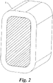
- the inner circumferential surface of the air-core coil 1 is a surface orthogonal to the winding axial direction of the hollow portion of the cylindrical air-core coil 1 (hatching portion in Fig. 2 ). That is, the magnetic bodies 2 are arranged to face each other so as to sandwich the air-core coil 1 therebetween.
- the magnetic sensor 3 detects the magnetic state of the reactor 10.
- the magnetic sensor 3 detects the magnetic flux flowing in the reactor 10.
- the magnetic sensor 3 is formed by the conductive member.
- the magnetic sensor 3 is formed by winding the conductive member, and for example, a number of windings is one or less. By reducing number of windings to one or less, a process of winding the conductive member is minimized, improving productivity thereof and reducing the material cost.
- the magnetic sensor 3 has a substantially U-shape in which two portions of the conductive member are bent in substantially right angle to form a width portion and two length portion extending from both sides of the width portion.
- the magnetic sensor 3 is arranged at regions other than an extended region of the inner circumferential surface of the air-core coil 1.
- the magnetic sensor 3 is wound around an outer circumference of a substantially central portion of one of the magnetic bodies 2.
- the width portion of the magnetic sensor 3 is sandwiched by the magnetic body 2 and the casing 4, and the two length portions of the magnetic sensor 3 sandwich the magnetic body 2.
- the magnetic sensor 3 is arranged between two air-core coils 1. Note that since the magnetic sensor 3 of the present embodiment does not measure total amount of the magnetic flux, but only detects changes in the magnetic flux for each time, the detection function would not be affected even when the magnetic sensor 3 is arranged between two air-core coils 1.
- the magnetic sensor 3 is integrally molded and fixed with the magnetic body 2 by resins (unillustrated).
- resins for example, as types of the resins, epoxy resins, unsaturated polyester resins, urethane resins, BMC (Bulk Molding Compound), PPS (Polyphenylene Sulfide), and PBT (Polybutylene Terephthalate), etc., may be cited.
- the cross-sectional area of the conductive member forming the magnetic sensor 3 is smaller than the cross-sectional area of the conductive member forming the air-core coil 1.
- the cross-sectional area is not limited, for example, the cross-sectional area of the conductive member forming the magnetic sensor 3 is approximately one sixth of the conductive member forming the air-core coil 1. That is, when the cross-sectional area of the conductive member forming the air-core coil 1 is 6 mm2, the cross-sectional area of the conductive member forming the magnetic sensor 3 is 1 mm2.
- the reactor 10 includes a temperature sensor (unillustrated) to detect the temperature of the reactor 10.
- the temperature sensor is arranged between the air-core coil 1. Note that the temperature sensor may be integrally molded and fixed together with the magnetic body 2 and the magnetic sensor 3, or may be inserted and fixed to a holding portion in the resin.
- the casing 4 has a box-shape with an upper surface opened.
- the casing 4 houses the air-core coil 1, the magnetic body 2, the magnetic sensor 3, and the temperature sensor.
- the casing 4 is formed of a light weight metal with high thermal conductivity, such as an aluminum alloy and has heat dissipation effect.
- a filler may be injected into the casing 4.
- relatively soft resins with high thermal conductivity such as silicone resins, urethane resins, epoxy resins, and acrylic resins is suitable.
- a magnetic sensor 103 is arranged in an extended region of an inner circumferential surface of the air-core coil 101 to detect more magnetic flux. Since the magnetic flux generated from the air-core coil 101 expands toward a magnetic body 102 and since the magnetic flux flowing in the magnetic body 102 flows toward the air-core coil 101, a part of the magnetic flux may hit not only the inner circumferential portion of the magnetic sensor 103, but also the end surface of the conductive metal. When the magnetic flux hits the end surface of the conductive member, eddy current loss increases, and as a result, the heat generation becomes larger.
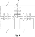
- the magnetic sensor 3 is arranged is not arranged in the extended region of the inner circumferential surface of the air-core coil 1, and is arranged at the substantially central portion of the magnetic body 2 and between the air-core coil 1. Therefore, as illustrated in Fig. 3 , the magnetic flux generated from the air-core coil 1 enters the magnetic body 2, passes through the inner circumference of the magnetic sensor 3 to flow through inside the magnetic body 2, and flows from the magnetic body 2 to the air-core coil 1. That is, the magnetic flux is prevented from hitting the magnetic sensor 3.
- the magnetic sensor 3 can detect the magnetic flux flowing in the magnetic body 2 that is the magnetic path.
- the reactor 10 of the present embodiment includes the air-core coil 1 formed by winding the conductive member, the magnetic body 2 arranged to face the inner circumferential surface the air-core coil 1 orthogonal to the winding axial direction; and the magnetic sensor formed by winding the conducive member around the outer circumference of the magnetic body 2 to detect the magnetic state of the reactor 10.
- the magnetic sensor 3 is wound around the outer circumference of the magnetic body 2 other than an extended region of the inner circumferential surface of the air-core coil 1.
- the magnetic flux is prevented from hitting the magnetic sensor 3
- eddy current loss can be suppressed. Accordingly, by suppressing eddy current loss, the heat generation of the magnetic sensor 3 can be suppressed. As a result, eddy current loss of the reactor 10 and the amount of heat generated from the reactor 10 can be reduced.
- the magnetic sensor 3 is arranged in the outer circumference of the magnetic body 2, the change amount of the magnetic flux flowing in the magnetic body 2 that is the magnetic path can be measured, serving as a sensor.
- the cross-sectional area of the conductive member forming the magnetic sensor 3 is smaller than the cross-sectional area of the conductive member forming the air-core coil
- the magnetic sensor 103 when the magnetic sensor 103 is arranged the extended region of the inner circumferential surface of the air-core coil 101, the amount of heat generated by the magnetic sensor 103 becomes large. To improve the heat dissipation, it is required to make the conductive member forming the magnetic sensor 103 thicker, that is, it is required to increase the cross-sectional area and diameter of the conductive member.
- the cross-sectional area of the conductive member forming the magnetic sensor 3 can be made smaller, and as a result, the diameter of the magnetic sensor 3 can be made smaller. Therefore, the magnetic sensor 3 can be downsized, and as a result, the reactor 10 can be downsized.
- two air-core coils are provided, and the two air-core coils 1 are arranged side by side so that the winding axial directions become parallel to each other.
- the magnetic sensor 3 is arranged between the air-core coils 1, and the temperature sensor to detect the temperature of the reactor 10 is arranged between the air-core coils 1.
- the diameter of the magnetic sensor 3 can be made smaller. Therefore, the gap between the air-core coils 1 arranged side by side can be made smaller.
- the temperature sensor can detect the temperature more precisely when it is arranged at the position closer to the air-core coil 1. Therefore, by arranging the temperature sensor between the air-core coils 1 having smaller gaps therebetween, the temperature of the reactor 10 can be detected more precisely.
- the magnetic sensor 3 is integrally molded and fixed with the magnetic body 2 by resins. By this, since the magnetic sensor 3 is suppressed from being displaced even when the reactor 10 vibrates, excellent detection state can be maintained. Furthermore, by molding the magnetic sensor 3 integrally with the magnetic body 2, a process of fixing the magnetic sensor 3 can be omitted, improving the productivity.
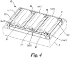
- FIG. 4 is a perspective view illustrating an entire configuration of the reactor according to the second embodiment.
- Fig. 5 is a plan view of the reactor according to the second embodiment.
- the reactor 10 according to second embodiment has different numbers of the air-core coils 1, different shapes of the magnetic body 2, and different numbers of the magnetic sensors 3 compared to the first embodiment.
- Three air-core coils 1 are arranged side by side via the gaps so that the winding axial directions become parallel to each other.
- an air-core coil 1b is arranged at the center, and air-core coils 1a and 1c are arranged at both sides of the air-core coil 1b and sandwich the air-core coil 1b.
- the magnetic body 2 includes a protruding portion 21.
- This protruding portion 2 is also formed of a powder magnetic core, a ferrite core, a laminated steel sheet, or a metal composite, and becomes a magnetic path through which the magnetic flux flows.
- the protruding portion 21 extends from a surface facing the air-core coils 1a, 1b, and 1c toward the air-core coils 1a, 1b, and 1c.
- the magnetic body includes the same number of protruding portions as the number of the air-core coils 1.
- the protruding portions 21 of respective magnetic bodies 2 sandwich the air-core coils 1 and are arranged to face each other.
- the protruding portions 21 may be inserted into the inner circumferences of the air-core coils 1a, 1b, and 1c. Note that total length of the facing protruding portions 21 inserted in the inner circumference of the air-core coil 1 is equal to or less than half the length of the air-core coil 1 in the winding axial direction. That is, as illustrated in Fig. 6 , when the lengths of the facing protruding portions 21 inserted in the inner circumference of the air-core coil 1 in the winding axial direction are respectively L1 and L2, and the length of the air-core coil 1 in the winding axial direction is L3, (L1 + L2) ⁇ (L3/2) is met. That is, the air-core coil 1 of the present disclosure includes an air-core coil in which equal to or more than half of the inner circumference is hollow.
- a space between the facing protruding portions 21 is not the gap.
- the gap makes a magnetic gap with predetermined width between the magnetic bodies so that the reduction in the inductance of the reactor 10 is prevented.
- the inductance value of the air-core coil 1 does not depend on the current value and is constant, there is no need to prevent the reduction in the inductance in the first place. Therefore, equal to or more than half of the inner circumference of the air-core coil 1 that is the hollow portion is different from the gap to prevent the reduction in inductance.
- the protruding portion 21 is provided to suppress the magnetic flux from expanding and hitting the end surface of the conductive member forming the air-core coil 1.
- the reactor 10 of the present embodiment includes a plate-shape magnetic body 22.
- Four plate-shape magnetic bodies 22 are provided respectively provided between the air-core coils 1a and 1b, between the air-core coils 1b and 1c, and at both end portions of the magnetic body 2.
- the plate-shape magnetic body 22 is joined to the magnetic body 2 by, for example, adhesives.
- the magnetic sensor 3a is provided between the air-core coil 1a and the plate-shape magnetic body 22, the magnetic sensor 3b is provided between the air-core coils 1a and 1b, and the magnetic sensor 3c is provided between the air-core coil 1c and the plate-shape magnetic body 22, in the outer circumference of one of the magnetic bodies 2, respectively.
- Three magnetic sensors 3a, 3b, and 3c are all provided in the outer circumference of the magnetic body 2 other than the extended region of the inner circumferential surface of the air-core coil 1 orthogonal to the winding axial direction.
- Fig. 7 is a figure illustrating a flow of the magnetic flux in a case the protruding portion is not provided.
- Fig. 8 is a figure illustrating a flow of magnetic flux in the second embodiment. Note that arrows in Figs. 7 and 8 indicates a flow of the magnetic flux.
- the magnetic flux generated from the air-core coil 1 flows toward the protruding portion 21, the magnetic flux is suppressed from expanding in the boundary between the air-core coil 1 and the magnetic body 2. Furthermore, the magnetic flux that has flowed the magnetic body 2 also flows in the protruding portion 21 and flows from a tip of the protruding portion 21 to the air-core coil 1. As a result, the magnetic flux is suppressed from hitting the end surface of the conductive member forming the air-core coil 1.
- the magnetic body 2 includes the protruding portion 21 extending from the surface facing the air-core coil 1 toward the air-core coil 1.
- the magnetic flux is suppressed from hitting the end surface of the conductive member forming the air-core coil 1.
- eddy current loss of the reactor 10 is reduced, and the amount of heat generation of the reactor 10 is reduced.
- reactors of examples 1 and 2 and comparative examples 1 and 2 are produced.
- the examples 1 has the same configuration as the first embodiment ( Fig. 1 ).
- the magnetic sensor is arranged between the air-core coil and the magnetic body (extended region of the inner circumferential surface of the air-core coil).
- the example 1 and the comparative example 1 only differ in the position of the magnetic sensor, and other configurations and members are the same.
- the examples 2 has the same configuration as the second embodiment ( Figs. 4 and 5 ). Meanwhile, as illustrated in Fig. 10 , in the comparative example 1, the magnetic sensor is arranged in the outer circumference of the magnetic body including the protruding portion (extended region of the inner circumferential surface of the air-core coil).
- the example 2 and the comparative example 2 only differ in the position of the magnetic sensor, and other configurations and members are the same.
- Eddy current losses of the magnetic sensors arranged at the positions in the examples 1 and 2 and the comparative examples 1 and 2 are acquired from the simulation of the magnetic field analysis.
- the magnetic field analysis for the example 1 and the comparative example 1 are performed under the condition of 30 A of current and 163.66 mT of the magnetic flux density ⁇ B.
- the magnetic field analysis for the example 2 and the comparative example 2 are performed under the condition of 30 A of the current and 224.52 mT of the magnetic flux density ⁇ B.
- the analysis result for the example 1 and the comparative example 1 are indicated in Table 1
- the analysis result for the example 2 and the comparative example 2 are indicated in Table 2.
- Example 1 Comparative Example 1 Eddy Current Loss (W) 0.32 9.64
- Example 2 Comparative Example 2 Eddy Current Loss (W) a b c a b c 0.22 0.21 0.23 10.25 10.13 8.93
- the example 1 can significantly reduce eddy current loss down to 1/30 or less compared to the comparative example 1.
- the example 2 can significantly reduce eddy current loss in each three magnetic sensors down to 1/40 or less compared to the comparative example 2. That is, it is observed that, by providing the magnetic sensor in the outer circumference of the magnetic body other than the extended region of the inner circumferential surface of the air-core coil 1, eddy current loss can be significantly reduced.
- the magnetic sensor is integrally molded and fixed with the magnetic body 2 by resins, it is not limited thereto.
- the magnetic body 2 may be molded by resins
- a holding portion for the magnetic sensor may be formed by resins at the time of molding, and the magnetic sensor 3 may be held by the holding portion.
- the reactor 10 includes the temperature sensor between the air-core coil 1
- any sensors may be provided as long as the sensor can shorten the distance between the air-core coil 1 and can improve the detection accuracy of the state of the reactor 10.
- the second embodiment although three magnetic sensors 3 are all arranged in the outer circumference of the magnetic body 2 other than the extended region of the inner circumference surface of the air-core coil 1 orthogonal to the winding axial direction, when a plurality of the magnetic sensors 3 are provide in the reactor 10, at least one magnetic senser 1 may be arranged in the outer circumference of the magnetic body 2 other than the extended region of the inner circumference surface of the air-core coil 1 orthogonal to the winding axial direction.
Landscapes
- Engineering & Computer Science (AREA)
- Power Engineering (AREA)
- Coils Or Transformers For Communication (AREA)
- Measuring Magnetic Variables (AREA)
Abstract
Description
- This application is based upon and claims the benefit of priority from
Japan Patent Application No. 2021-040330, filed on March 12, 2021 - The present disclosure relates to a reactor including a magnetic sensor formed by conductive members.
- Reactors are used in various applications such as office automation apparatuses, solar power generation systems, automobiles, etc. The reactor includes a coil and a magnetic body arranged on both end surfaces which are orthogonal to the winding axial direction of the coil. The coil is electrically connected to external devices, and generates magnetic flux when electric power is supplied from the external devices. The magnetic body becomes a magnetic path through which the magnetic flux generated by the coil passes. Accordingly, the reactor is an electromagnetic component that converts electric energy into magnetic energy, and stores and releases said energy.
- The reactor may include a magnetic sensor formed by winding conductive members to detect magnetic field. To detect more magnetic flux, the magnetic sensor is arranged to face the end surface orthogonal to the winding axial direction of the coil and between the coil and the magnetic body. That is, the magnetic sensor is arranged in the extended region of the inner circumferential surface that is the hollow portion of the coil.
- An air-core coil may be used as the coil. When the magnetic body is inserted in the inner circumference of the coil, since the magnetic body becomes the magnetic path, the magnetic flux is unlikely to hit the end surface of the conductive member forming the magnetic sensor, except for the leakage flux. On the other hand, when the air-core coil is used, the magnetic flux generated from the air-core coil expands in the boundary between the air-core coil and the magnetic body, and the amount of the magnetic flux hitting the end surface of the conductive member forming the magnetic sensor is large in comparison with a case in which the magnetic body is inserted in the inner circumference of the coil.
- In detail, as illustrated in
Fig. 11 , the magnetic flux generated by the air-core coil 101 flows toward the magnetic body 102 (an arrow inFig. 11 indicates the flow of the magnetic flux). Accordingly, the magnetic flux expands from the end portion of the air-core coil toward the magnetic body 102 (a portion circled by a dashed line inFig. 11 ), the leakage flux does not pass through the inner circumference of themagnetic sensor 103 and may hit the end surface of themagnetic sensor 103. Similarly, the magnetic flux flowing through themagnetic body 102 may flow toward the air-core coil 101 and may hit the end surface of themagnetic sensor 103. - When the magnetic flux hits the end surface of the magnetic sensor, eddy current loss is produced in the magnetic sensor. Therefore, as the amount of the magnetic flux hitting the end surface of the magnetic sensor increases, eddy current loss also increases. Accordingly, the magnetic sensor generates heat in proportion to the increase in eddy current loss, and as a result, the amount of heat generated by the reactor also increases.
- The present disclosure has been made to address the above described problem, and the objective is to provide a reactor that can suppress magnetic flux from hitting the end surfaces of the magnetic sensor and that can reduce eddy current loss and the amount of generated heat.
- A reactor of the present disclosure includes:
- an air-core coil formed by winding a conductive member in a cylindrical shape;
- a magnetic body arranged to face an inner circumferential surface that is a hollow portion of the air-core coil orthogonal to a winding axial direction; and
- a magnetic sensor formed by winding the conducive member to detect a magnetic state of the reactor,
- wherein the magnetic sensor is wound around an outer circumference of the magnetic body other than an extended region of the inner circumferential surface of the air-core coil.
- According to the present disclosure, a reactor that can suppress magnetic flux from hitting the end surfaces of the magnetic sensor and that can reduce eddy current loss and the amount of generated heat can be obtained.
-
-
Fig. 1 is a perspective view illustrating an entire configuration of a reactor according to a first embodiment. -
Fig. 2 is a figure illustrating an inner circumference surface of an air-core coil. -
Fig. 3 is a figure illustrating a flow of magnetic flux in the first embodiment. -
Fig. 4 is a perspective view illustrating an entire configuration of a reactor according to a second embodiment. -
Fig. 5 is a plan view of the reactor according to the second embodiment. -
Fig. 6 is a schematic diagram illustrating lengths of a protruding portion and the air-core coil. -
Fig. 7 is a figure illustrating a flow of the magnetic flux in a case the protruding portion is not provided. -
Fig. 8 is a figure illustrating a flow of magnetic flux in the second embodiment. -
Fig 9 is a perspective view illustrating an entire configuration of a comparative example 1. -
Fig. 10 is a plan view illustrating an entire configuration of a comparative example 2. -
Fig. 11 is a figure illustrating a flow of the magnetic flux in a case the protruding portion is provided at a conventional position. - A reactor according to a first embodiment is described with the reference to figures.
Fig. 1 is a perspective view illustrating an entire configuration of the reactor. Thereactor 10 is an electromagnetic component that converts electric energy into magnetic energy, stores and releases said energy, and is used in various applications such as office automation apparatuses, solar power generation systems, automobiles, etc. The reactor of the first embodiment includes an air-core coil 1, amagnetic body 2, amagnetic sensor 3, and acasing 4. - The air-
core coil 1 is formed by one flat rectangular conductive member coated with an insulation coating such as enamel. The air-core coil 1 is formed by winding the conductive member in a cylindrical shape while displacing the winding position in the winding axial direction, and an inner circumference portion thereof is a hollow portion to which themagnetic body 2 is not inserted. In the present embodiment, the air-core coil 1 is a flat wire edgewise coil formed by copper wires. However, types of wire materials and winding methods of the air-core coil 1 is not limited, and other forms may be applied. - The air-
core coil 1 in which the magnetic body is not inserted into the inner circumference is characterized in that the inductance value is constant regardless of the current value flowing through the coil. In contrast, the coil in which the magnetic body is inserted in the inner circumference is characterized in that the magnetic body saturates and the inductance value decreases as the current value flowing through the coil increases. Therefore, the characteristics largely differ between the air-core coil 1 of the present invention and the coil in which the magnetic body is inserted in the inner circumference. - Two air-core coils are provided. The air-
core coil 1 is arranged side by side via a gap so that the winding axial directions become parallel to each other. Note that in the air-core coil 1, an end portion of the conductive member is electrically connected to external devices, and magnetic flux is generated when electricity is supplied from the external devices. - The
magnetic body 2 becomes a magnetic path through which the magnetic flux generated by the air-core coil 1 flows. Themagnetic body 2 may be a powder magnetic core, a ferrite core, a laminated steel sheet, or a metal composite. The metal composite is a magnetic body formed by kneading a magnetic powder and a resin and curing the resin. - The
magnetic body 2 has a substantially rectangular shape, and twomagnetic bodies 2 is provided. Themagnetic bodies 2 each arranged to face an inner circumferential surface of the air-core coil 1 orthogonal to the winding axial direction. The inner circumferential surface of the air-core coil 1 is a surface orthogonal to the winding axial direction of the hollow portion of the cylindrical air-core coil 1 (hatching portion inFig. 2 ). That is, themagnetic bodies 2 are arranged to face each other so as to sandwich the air-core coil 1 therebetween. - The
magnetic sensor 3 detects the magnetic state of thereactor 10. In detail, themagnetic sensor 3 detects the magnetic flux flowing in thereactor 10. Themagnetic sensor 3 is formed by the conductive member. Themagnetic sensor 3 is formed by winding the conductive member, and for example, a number of windings is one or less. By reducing number of windings to one or less, a process of winding the conductive member is minimized, improving productivity thereof and reducing the material cost. Themagnetic sensor 3 has a substantially U-shape in which two portions of the conductive member are bent in substantially right angle to form a width portion and two length portion extending from both sides of the width portion. - The
magnetic sensor 3 is arranged at regions other than an extended region of the inner circumferential surface of the air-core coil 1. Themagnetic sensor 3 is wound around an outer circumference of a substantially central portion of one of themagnetic bodies 2. In detail, the width portion of themagnetic sensor 3 is sandwiched by themagnetic body 2 and thecasing 4, and the two length portions of themagnetic sensor 3 sandwich themagnetic body 2. Themagnetic sensor 3 is arranged between two air-core coils 1. Note that since themagnetic sensor 3 of the present embodiment does not measure total amount of the magnetic flux, but only detects changes in the magnetic flux for each time, the detection function would not be affected even when themagnetic sensor 3 is arranged between two air-core coils 1. - The
magnetic sensor 3 is integrally molded and fixed with themagnetic body 2 by resins (unillustrated). For example, as types of the resins, epoxy resins, unsaturated polyester resins, urethane resins, BMC (Bulk Molding Compound), PPS (Polyphenylene Sulfide), and PBT (Polybutylene Terephthalate), etc., may be cited. - The cross-sectional area of the conductive member forming the
magnetic sensor 3 is smaller than the cross-sectional area of the conductive member forming the air-core coil 1. Although the cross-sectional area is not limited, for example, the cross-sectional area of the conductive member forming themagnetic sensor 3 is approximately one sixth of the conductive member forming the air-core coil 1. That is, when the cross-sectional area of the conductive member forming the air-core coil 1 is 6 mm2, the cross-sectional area of the conductive member forming themagnetic sensor 3 is 1 mm2. - Furthermore, the
reactor 10 includes a temperature sensor (unillustrated) to detect the temperature of thereactor 10. The temperature sensor is arranged between the air-core coil 1. Note that the temperature sensor may be integrally molded and fixed together with themagnetic body 2 and themagnetic sensor 3, or may be inserted and fixed to a holding portion in the resin. - The
casing 4 has a box-shape with an upper surface opened. Thecasing 4 houses the air-core coil 1, themagnetic body 2, themagnetic sensor 3, and the temperature sensor. For example, thecasing 4 is formed of a light weight metal with high thermal conductivity, such as an aluminum alloy and has heat dissipation effect. Note that, after the air-core coil 1, themagnetic body 2, themagnetic sensor 3, and the temperature sensor are housed in thecasing 4, a filler may be injected into thecasing 4. As the filler, relatively soft resins with high thermal conductivity such as silicone resins, urethane resins, epoxy resins, and acrylic resins is suitable. - As illustrated in
Fig. 11 , conventionally, amagnetic sensor 103 is arranged in an extended region of an inner circumferential surface of the air-core coil 101 to detect more magnetic flux. Since the magnetic flux generated from the air-core coil 101 expands toward amagnetic body 102 and since the magnetic flux flowing in themagnetic body 102 flows toward the air-core coil 101, a part of the magnetic flux may hit not only the inner circumferential portion of themagnetic sensor 103, but also the end surface of the conductive metal. When the magnetic flux hits the end surface of the conductive member, eddy current loss increases, and as a result, the heat generation becomes larger. - However, in the present embodiment, the
magnetic sensor 3 is arranged is not arranged in the extended region of the inner circumferential surface of the air-core coil 1, and is arranged at the substantially central portion of themagnetic body 2 and between the air-core coil 1. Therefore, as illustrated inFig. 3 , the magnetic flux generated from the air-core coil 1 enters themagnetic body 2, passes through the inner circumference of themagnetic sensor 3 to flow through inside themagnetic body 2, and flows from themagnetic body 2 to the air-core coil 1. That is, the magnetic flux is prevented from hitting themagnetic sensor 3. Furthermore, since the width portion of themagnetic sensor 3 is sandwiched by themagnetic body 2 and thecasing 4, and the two length portions of themagnetic sensor 3 is provided in the outer circumference of themagnetic body 2 so as to sandwich themagnetic body 2, themagnetic sensor 3 can detect the magnetic flux flowing in themagnetic body 2 that is the magnetic path. - As described above, the
reactor 10 of the present embodiment includes the air-core coil 1 formed by winding the conductive member, themagnetic body 2 arranged to face the inner circumferential surface the air-core coil 1 orthogonal to the winding axial direction; and the magnetic sensor formed by winding the conducive member around the outer circumference of themagnetic body 2 to detect the magnetic state of thereactor 10. In addition, themagnetic sensor 3 is wound around the outer circumference of themagnetic body 2 other than an extended region of the inner circumferential surface of the air-core coil 1. - By this, since the magnetic flux is prevented from hitting the
magnetic sensor 3, eddy current loss can be suppressed. Accordingly, by suppressing eddy current loss, the heat generation of themagnetic sensor 3 can be suppressed. As a result, eddy current loss of thereactor 10 and the amount of heat generated from thereactor 10 can be reduced. In addition, since themagnetic sensor 3 is arranged in the outer circumference of themagnetic body 2, the change amount of the magnetic flux flowing in themagnetic body 2 that is the magnetic path can be measured, serving as a sensor. - The cross-sectional area of the conductive member forming the
magnetic sensor 3 is smaller than the cross-sectional area of the conductive member forming the air-core coil - 1. By this, the
magnetic sensor 3 can be downsized, and as a result, thereactor 10 can be downsized. - Conventionally, when the
magnetic sensor 103 is arranged the extended region of the inner circumferential surface of the air-core coil 101, the amount of heat generated by themagnetic sensor 103 becomes large. To improve the heat dissipation, it is required to make the conductive member forming themagnetic sensor 103 thicker, that is, it is required to increase the cross-sectional area and diameter of the conductive member. - However, in the present embodiment, since the amount of heat generated by the
magnetic sensor 3 can be reduces such that it is not required to improve the heat dissipation of themagnetic sensor 3, the cross-sectional area of the conductive member forming themagnetic sensor 3 can be made smaller, and as a result, the diameter of themagnetic sensor 3 can be made smaller. Therefore, themagnetic sensor 3 can be downsized, and as a result, thereactor 10 can be downsized. - Furthermore, two air-core coils are provided, and the two air-
core coils 1 are arranged side by side so that the winding axial directions become parallel to each other. Themagnetic sensor 3 is arranged between the air-core coils 1, and the temperature sensor to detect the temperature of thereactor 10 is arranged between the air-core coils 1. - As described above, since the amount heat generated by the
magnetic sensor 3 can be suppressed, the diameter of themagnetic sensor 3 can be made smaller. Therefore, the gap between the air-core coils 1 arranged side by side can be made smaller. The temperature sensor can detect the temperature more precisely when it is arranged at the position closer to the air-core coil 1. Therefore, by arranging the temperature sensor between the air-core coils 1 having smaller gaps therebetween, the temperature of thereactor 10 can be detected more precisely. - The
magnetic sensor 3 is integrally molded and fixed with themagnetic body 2 by resins. By this, since themagnetic sensor 3 is suppressed from being displaced even when thereactor 10 vibrates, excellent detection state can be maintained. Furthermore, by molding themagnetic sensor 3 integrally with themagnetic body 2, a process of fixing themagnetic sensor 3 can be omitted, improving the productivity. - A reactor according to a second embodiment will be described with the reference to figures. Note that same configurations and same functions as the first embodiment are labeled with same reference signs and descriptions thereof are omitted, and only different parts are described.
Fig. 4 is a perspective view illustrating an entire configuration of the reactor according to the second embodiment.Fig. 5 is a plan view of the reactor according to the second embodiment. - The
reactor 10 according to second embodiment has different numbers of the air-core coils 1, different shapes of themagnetic body 2, and different numbers of themagnetic sensors 3 compared to the first embodiment. Three air-core coils 1 are arranged side by side via the gaps so that the winding axial directions become parallel to each other. In detail, an air-core coil 1b is arranged at the center, and air-core coils core coil 1b and sandwich the air-core coil 1b. - The
magnetic body 2 includes a protrudingportion 21. This protrudingportion 2 is also formed of a powder magnetic core, a ferrite core, a laminated steel sheet, or a metal composite, and becomes a magnetic path through which the magnetic flux flows. The protrudingportion 21 extends from a surface facing the air-core coils core coils core coils 1. The protrudingportions 21 of respectivemagnetic bodies 2 sandwich the air-core coils 1 and are arranged to face each other. - The protruding
portions 21 may be inserted into the inner circumferences of the air-core coils portions 21 inserted in the inner circumference of the air-core coil 1 is equal to or less than half the length of the air-core coil 1 in the winding axial direction. That is, as illustrated inFig. 6 , when the lengths of the facing protrudingportions 21 inserted in the inner circumference of the air-core coil 1 in the winding axial direction are respectively L1 and L2, and the length of the air-core coil 1 in the winding axial direction is L3, (L1 + L2)≦(L3/2) is met. That is, the air-core coil 1 of the present disclosure includes an air-core coil in which equal to or more than half of the inner circumference is hollow. - Note that a space between the facing protruding
portions 21 is not the gap. The gap makes a magnetic gap with predetermined width between the magnetic bodies so that the reduction in the inductance of thereactor 10 is prevented. As described above, since the inductance value of the air-core coil 1 does not depend on the current value and is constant, there is no need to prevent the reduction in the inductance in the first place. Therefore, equal to or more than half of the inner circumference of the air-core coil 1 that is the hollow portion is different from the gap to prevent the reduction in inductance. As described later, the protrudingportion 21 is provided to suppress the magnetic flux from expanding and hitting the end surface of the conductive member forming the air-core coil 1. - Furthermore, the
reactor 10 of the present embodiment includes a plate-shapemagnetic body 22. Four plate-shapemagnetic bodies 22 are provided respectively provided between the air-core coils core coils magnetic body 2. The plate-shapemagnetic body 22 is joined to themagnetic body 2 by, for example, adhesives. - Three
magnetic sensors 3 are provided. Themagnetic sensor 3a is provided between the air-core coil 1a and the plate-shapemagnetic body 22, themagnetic sensor 3b is provided between the air-core coils magnetic sensor 3c is provided between the air-core coil 1c and the plate-shapemagnetic body 22, in the outer circumference of one of themagnetic bodies 2, respectively. Threemagnetic sensors magnetic body 2 other than the extended region of the inner circumferential surface of the air-core coil 1 orthogonal to the winding axial direction. - Next, the action of the second embodiment is described with the reference to the figures.
Fig. 7 is a figure illustrating a flow of the magnetic flux in a case the protruding portion is not provided.Fig. 8 is a figure illustrating a flow of magnetic flux in the second embodiment. Note that arrows inFigs. 7 and8 indicates a flow of the magnetic flux. - As described above, since the magnetic flux generated from the air-
core coil 1 expands toward themagnetic body 2 and since the magnetic flux flowing in themagnetic body 2 flows toward the air-core coil 1, the magnetic flux hit the end surface of the conductive member forming the air-core coil 1,eddy current loss may increase (surrounded by a dashed circle inFig. 7 ). - However, as illustrated in
Fig. 8 , by providing the protrudingportion 21 to themagnetic body 2, since the magnetic flux generated from the air-core coil 1 flows toward the protrudingportion 21, the magnetic flux is suppressed from expanding in the boundary between the air-core coil 1 and themagnetic body 2. Furthermore, the magnetic flux that has flowed themagnetic body 2 also flows in the protrudingportion 21 and flows from a tip of the protrudingportion 21 to the air-core coil 1. As a result, the magnetic flux is suppressed from hitting the end surface of the conductive member forming the air-core coil 1. - As described above, in the
reactor 10 of the present embodiment, themagnetic body 2 includes the protrudingportion 21 extending from the surface facing the air-core coil 1 toward the air-core coil 1. By this, the magnetic flux is suppressed from hitting the end surface of the conductive member forming the air-core coil 1. As a result, eddy current loss of thereactor 10 is reduced, and the amount of heat generation of thereactor 10 is reduced. - The present disclosure is further described in detail based on examples. Note that the present disclosure is not limited to the following examples.
- Firstly, reactors of examples 1 and 2 and comparative examples 1 and 2 are produced. The examples 1 has the same configuration as the first embodiment (
Fig. 1 ). Meanwhile, as illustrated inFig. 9 , in the comparative example 1, the magnetic sensor is arranged between the air-core coil and the magnetic body (extended region of the inner circumferential surface of the air-core coil). The example 1 and the comparative example 1 only differ in the position of the magnetic sensor, and other configurations and members are the same. - The examples 2 has the same configuration as the second embodiment (
Figs. 4 and5 ). Meanwhile, as illustrated inFig. 10 , in the comparative example 1, the magnetic sensor is arranged in the outer circumference of the magnetic body including the protruding portion (extended region of the inner circumferential surface of the air-core coil). The example 2 and the comparative example 2 only differ in the position of the magnetic sensor, and other configurations and members are the same. - Eddy current losses of the magnetic sensors arranged at the positions in the examples 1 and 2 and the comparative examples 1 and 2 are acquired from the simulation of the magnetic field analysis. The magnetic field analysis for the example 1 and the comparative example 1 are performed under the condition of 30 A of current and 163.66 mT of the magnetic flux density ΔB. In addition, the magnetic field analysis for the example 2 and the comparative example 2 are performed under the condition of 30 A of the current and 224.52 mT of the magnetic flux density ΔB. The analysis result for the example 1 and the comparative example 1 are indicated in Table 1, and the analysis result for the example 2 and the comparative example 2 are indicated in Table 2. Note that a, b, and c in Table 2 respectively indicate the
magnetic sensor Figs. 4 and10 .[Table 1] Example 1 Comparative Example 1 Eddy Current Loss (W) 0.32 9.64 [Table 2] Example 2 Comparative Example 2 Eddy Current Loss (W) a b c a b c 0.22 0.21 0.23 10.25 10.13 8.93 - As indicated in Table 1, it is observed that the example 1 can significantly reduce eddy current loss down to 1/30 or less compared to the comparative example 1. In addition, it is observed that the example 2 can significantly reduce eddy current loss in each three magnetic sensors down to 1/40 or less compared to the comparative example 2. That is, it is observed that, by providing the magnetic sensor in the outer circumference of the magnetic body other than the extended region of the inner circumferential surface of the air-
core coil 1, eddy current loss can be significantly reduced. - In the present specification, although embodiments according to the present invention have been described, said embodiments are only provided as examples and are intended to limit the scope of invention. Above-described embodiments can be implemented in other various forms, and various omissions, replacements, and modifications may performed without departing from the scope of invention. Embodiments and modifications thereof are included in the scope and abstract of the invention, and are included in the invention described in the claims of the invention and equivalent ranges thereto.
- In the present embodiment, although the magnetic sensor is integrally molded and fixed with the
magnetic body 2 by resins, it is not limited thereto. For example, only themagnetic body 2 may be molded by resins, a holding portion for the magnetic sensor may be formed by resins at the time of molding, and themagnetic sensor 3 may be held by the holding portion. - In the present embodiment, although the
reactor 10 includes the temperature sensor between the air-core coil 1, any sensors may be provided as long as the sensor can shorten the distance between the air-core coil 1 and can improve the detection accuracy of the state of thereactor 10. - In the second embodiment, although three
magnetic sensors 3 are all arranged in the outer circumference of themagnetic body 2 other than the extended region of the inner circumference surface of the air-core coil 1 orthogonal to the winding axial direction, when a plurality of themagnetic sensors 3 are provide in thereactor 10, at least onemagnetic senser 1 may be arranged in the outer circumference of themagnetic body 2 other than the extended region of the inner circumference surface of the air-core coil 1 orthogonal to the winding axial direction. -
- 10: reactor1: air-core coil
- 1a, 1b, 1c: air-core coil
- 2: magnetic body
- 21: protruding portion
- 22: plate-shape magnetic body
- 3: magnetic sensor
- 3a, 3b, 3c: magnetic sensor
- 4: casing
- 100: reactor
- 101: air-core coil
- 102: magnetic body
- 103: magnetic sensor
Claims (5)
- A reactor comprising:an air-core coil formed by winding a conductive member in a cylindrical shape;a magnetic body arranged to face an inner circumferential surface that is a hollow portion of the air-core coil orthogonal to a winding axial direction; anda magnetic sensor formed by winding the conducive member to detect a magnetic state of the reactor,wherein the magnetic sensor is wound around an outer circumference of the magnetic body other than an extended region of the inner circumferential surface of the air-core coil.
- The reactor according to claim 1, wherein the magnetic body includes a protruding portion extending from a surface facing the air-core coil toward the air-core coil.
- The reactor according to claim 1 or 2, wherein a cross-sectional area of the conductive member forming the magnetic sensor is smaller than a cross-sectional area of the conductive member forming the air-core coil.
- The reactor according to any one of claims 1 to 3, further comprising a sensor to detect a state of the reactor,
wherein:a plurality of the air-core coils is provided,the plurality of the air-core coils is arranged side by side so that the winding axial directions become parallel to each other,the magnetic sensor is arranged between the air-core coils, andthe sensor is arranged between the plurality of the air-core coils. - The reactor according to any one of claims 1 to 4, wherein the magnetic sensor is integrally molded and fixed with the magnetic body by resins.
Applications Claiming Priority (1)
| Application Number | Priority Date | Filing Date | Title |
|---|---|---|---|
| JP2021040330A JP7699445B2 (en) | 2021-03-12 | 2021-03-12 | Reactor |
Publications (1)
| Publication Number | Publication Date |
|---|---|
| EP4057307A1 true EP4057307A1 (en) | 2022-09-14 |
Family
ID=78725247
Family Applications (1)
| Application Number | Title | Priority Date | Filing Date |
|---|---|---|---|
| EP21209181.3A Withdrawn EP4057307A1 (en) | 2021-03-12 | 2021-11-19 | Reactor |
Country Status (3)
| Country | Link |
|---|---|
| EP (1) | EP4057307A1 (en) |
| JP (1) | JP7699445B2 (en) |
| CN (1) | CN115083752A (en) |
Families Citing this family (1)
| Publication number | Priority date | Publication date | Assignee | Title |
|---|---|---|---|---|
| JP2022154272A (en) * | 2021-03-30 | 2022-10-13 | 株式会社タムラ製作所 | Reactor |
Citations (5)
| Publication number | Priority date | Publication date | Assignee | Title |
|---|---|---|---|---|
| US20130049751A1 (en) * | 2010-04-14 | 2013-02-28 | Peter Hamberger | Method and apparatus for detecting a magnetic characteristic variable in a core |
| JP2013098302A (en) * | 2011-10-31 | 2013-05-20 | Sumitomo Electric Ind Ltd | Reactor |
| CN206602023U (en) * | 2017-03-23 | 2017-10-31 | 珠海市集森电器有限公司 | Novel dry air-core reactor |
| US20180330866A1 (en) * | 2015-12-10 | 2018-11-15 | Autonetworks Technologies, Ltd. | Reactor |
| JP2018206907A (en) * | 2017-06-02 | 2018-12-27 | 株式会社タムラ製作所 | Coil device |
Family Cites Families (9)
| Publication number | Priority date | Publication date | Assignee | Title |
|---|---|---|---|---|
| JPH0437008A (en) * | 1990-06-01 | 1992-02-07 | Hitachi Ltd | Reactor |
| JP2000036425A (en) * | 1998-07-21 | 2000-02-02 | Sht:Kk | Coil device having current detecting function |
| JP5060244B2 (en) * | 2007-10-26 | 2012-10-31 | 東芝変電機器テクノロジー株式会社 | Reactor |
| JP5252207B2 (en) * | 2008-03-31 | 2013-07-31 | 住友電気工業株式会社 | Reactor and converter |
| JP2010016234A (en) * | 2008-07-04 | 2010-01-21 | Hitachi Ferrite Electronics Ltd | Choke coil for interleave-controlled power factor correction circuit |
| US8089334B2 (en) * | 2009-02-05 | 2012-01-03 | General Electric Company | Cast-coil inductor |
| JP2013004725A (en) * | 2011-06-16 | 2013-01-07 | Sumitomo Electric Ind Ltd | Reactor |
| JP5708509B2 (en) * | 2012-01-25 | 2015-04-30 | トヨタ自動車株式会社 | Reactor |
| WO2020217109A1 (en) * | 2019-04-22 | 2020-10-29 | Abb Power Grids Switzerland Ag | Traction tranformer with a four-limb core |
-
2021
- 2021-03-12 JP JP2021040330A patent/JP7699445B2/en active Active
- 2021-11-15 CN CN202111350282.4A patent/CN115083752A/en active Pending
- 2021-11-19 EP EP21209181.3A patent/EP4057307A1/en not_active Withdrawn
Patent Citations (5)
| Publication number | Priority date | Publication date | Assignee | Title |
|---|---|---|---|---|
| US20130049751A1 (en) * | 2010-04-14 | 2013-02-28 | Peter Hamberger | Method and apparatus for detecting a magnetic characteristic variable in a core |
| JP2013098302A (en) * | 2011-10-31 | 2013-05-20 | Sumitomo Electric Ind Ltd | Reactor |
| US20180330866A1 (en) * | 2015-12-10 | 2018-11-15 | Autonetworks Technologies, Ltd. | Reactor |
| CN206602023U (en) * | 2017-03-23 | 2017-10-31 | 珠海市集森电器有限公司 | Novel dry air-core reactor |
| JP2018206907A (en) * | 2017-06-02 | 2018-12-27 | 株式会社タムラ製作所 | Coil device |
Also Published As
| Publication number | Publication date |
|---|---|
| CN115083752A (en) | 2022-09-20 |
| JP2022139793A (en) | 2022-09-26 |
| JP7699445B2 (en) | 2025-06-27 |
Similar Documents
| Publication | Publication Date | Title |
|---|---|---|
| US20100245016A1 (en) | Reactor for electrical devices | |
| KR101320170B1 (en) | Reactor | |
| US20130088317A1 (en) | Reactor and method of manufacturing the same | |
| US20120218066A1 (en) | Reactor | |
| US11721472B2 (en) | Coil component, circuit board, and power supply device | |
| EP2896115B1 (en) | Stator of rotating electric machine | |
| EP2597656A1 (en) | Reactor | |
| JP2010267932A (en) | Reactor | |
| JP7329901B2 (en) | Coil device | |
| CN116313495A (en) | A preparation method of conduction cooling variable wire diameter NbTi superconducting coil | |
| JP6635316B2 (en) | Reactor | |
| JP7255153B2 (en) | Reactor and manufacturing method thereof | |
| Cozonac et al. | Materials characterization and geometry of a high temperature induction machine | |
| CN112771633A (en) | Electric reactor | |
| JP7699445B2 (en) | Reactor | |
| CN103827990A (en) | Electrical device | |
| JP6513956B2 (en) | Magnetic coupling type reactor | |
| JP2016039322A (en) | Coil and coil component | |
| JP2018190910A (en) | Reactor device and method for manufacturing the same | |
| JP6809440B2 (en) | Reactor | |
| JP2012209327A (en) | Reactor | |
| CN112840419B (en) | Electric reactor | |
| JP2024155916A (en) | Reactor manufacturing method | |
| JP2016122764A (en) | Reactor | |
| US11469032B2 (en) | Wire harness and method for manufacturing the same |
Legal Events
| Date | Code | Title | Description |
|---|---|---|---|
| PUAI | Public reference made under article 153(3) epc to a published international application that has entered the european phase |
Free format text: ORIGINAL CODE: 0009012 |
|
| STAA | Information on the status of an ep patent application or granted ep patent |
Free format text: STATUS: THE APPLICATION HAS BEEN PUBLISHED |
|
| AK | Designated contracting states |
Kind code of ref document: A1 Designated state(s): AL AT BE BG CH CY CZ DE DK EE ES FI FR GB GR HR HU IE IS IT LI LT LU LV MC MK MT NL NO PL PT RO RS SE SI SK SM TR |
|
| STAA | Information on the status of an ep patent application or granted ep patent |
Free format text: STATUS: REQUEST FOR EXAMINATION WAS MADE |
|
| 17P | Request for examination filed |
Effective date: 20230314 |
|
| RBV | Designated contracting states (corrected) |
Designated state(s): AL AT BE BG CH CY CZ DE DK EE ES FI FR GB GR HR HU IE IS IT LI LT LU LV MC MK MT NL NO PL PT RO RS SE SI SK SM TR |
|
| GRAP | Despatch of communication of intention to grant a patent |
Free format text: ORIGINAL CODE: EPIDOSNIGR1 |
|
| STAA | Information on the status of an ep patent application or granted ep patent |
Free format text: STATUS: GRANT OF PATENT IS INTENDED |
|
| INTG | Intention to grant announced |
Effective date: 20250314 |
|
| RIN1 | Information on inventor provided before grant (corrected) |
Inventor name: HAMADA, TSUTOMU Inventor name: TSUSHIMA, ASAMI |
|
| STAA | Information on the status of an ep patent application or granted ep patent |
Free format text: STATUS: THE APPLICATION IS DEEMED TO BE WITHDRAWN |
|
| 18D | Application deemed to be withdrawn |
Effective date: 20250715 |