JP6809440B2 - Reactor - Google Patents
Reactor Download PDFInfo
- Publication number
- JP6809440B2 JP6809440B2 JP2017223948A JP2017223948A JP6809440B2 JP 6809440 B2 JP6809440 B2 JP 6809440B2 JP 2017223948 A JP2017223948 A JP 2017223948A JP 2017223948 A JP2017223948 A JP 2017223948A JP 6809440 B2 JP6809440 B2 JP 6809440B2
- Authority
- JP
- Japan
- Prior art keywords
- core piece
- inner core
- magnetic
- resin
- area
- Prior art date
- Legal status (The legal status is an assumption and is not a legal conclusion. Google has not performed a legal analysis and makes no representation as to the accuracy of the status listed.)
- Active
Links
- 229920005989 resin Polymers 0.000 claims description 161
- 239000011347 resin Substances 0.000 claims description 161
- 238000004804 winding Methods 0.000 claims description 109
- 230000035699 permeability Effects 0.000 claims description 61
- 230000002093 peripheral effect Effects 0.000 claims description 51
- 239000006247 magnetic powder Substances 0.000 claims description 25
- 239000002131 composite material Substances 0.000 claims description 15
- 239000002994 raw material Substances 0.000 description 42
- 230000004907 flux Effects 0.000 description 33
- 230000017525 heat dissipation Effects 0.000 description 10
- 238000000465 moulding Methods 0.000 description 10
- 230000015572 biosynthetic process Effects 0.000 description 9
- 239000000843 powder Substances 0.000 description 9
- 239000000470 constituent Substances 0.000 description 8
- 239000000463 material Substances 0.000 description 8
- 238000009434 installation Methods 0.000 description 7
- 239000002826 coolant Substances 0.000 description 6
- 239000000428 dust Substances 0.000 description 5
- 239000010410 layer Substances 0.000 description 4
- 230000005415 magnetization Effects 0.000 description 4
- 238000000034 method Methods 0.000 description 4
- 239000000203 mixture Substances 0.000 description 4
- 229920005992 thermoplastic resin Polymers 0.000 description 4
- 229920000106 Liquid crystal polymer Polymers 0.000 description 3
- 239000004977 Liquid-crystal polymers (LCPs) Substances 0.000 description 3
- 239000004952 Polyamide Substances 0.000 description 3
- 239000004734 Polyphenylene sulfide Substances 0.000 description 3
- 229910000831 Steel Inorganic materials 0.000 description 3
- 239000011230 binding agent Substances 0.000 description 3
- 239000011248 coating agent Substances 0.000 description 3
- 238000000576 coating method Methods 0.000 description 3
- 230000000694 effects Effects 0.000 description 3
- 230000004927 fusion Effects 0.000 description 3
- 238000010438 heat treatment Methods 0.000 description 3
- 238000001746 injection moulding Methods 0.000 description 3
- 239000007788 liquid Substances 0.000 description 3
- 239000000696 magnetic material Substances 0.000 description 3
- 238000004519 manufacturing process Methods 0.000 description 3
- 239000002184 metal Substances 0.000 description 3
- 229910052751 metal Inorganic materials 0.000 description 3
- 229920002647 polyamide Polymers 0.000 description 3
- 229920001707 polybutylene terephthalate Polymers 0.000 description 3
- 229920000069 polyphenylene sulfide Polymers 0.000 description 3
- -1 polytetrafluoroethylene Polymers 0.000 description 3
- 229920001343 polytetrafluoroethylene Polymers 0.000 description 3
- 239000004810 polytetrafluoroethylene Substances 0.000 description 3
- 239000003507 refrigerant Substances 0.000 description 3
- 239000010959 steel Substances 0.000 description 3
- 229920001187 thermosetting polymer Polymers 0.000 description 3
- 239000004412 Bulk moulding compound Substances 0.000 description 2
- VTYYLEPIZMXCLO-UHFFFAOYSA-L Calcium carbonate Chemical compound [Ca+2].[O-]C([O-])=O VTYYLEPIZMXCLO-UHFFFAOYSA-L 0.000 description 2
- RYGMFSIKBFXOCR-UHFFFAOYSA-N Copper Chemical compound [Cu] RYGMFSIKBFXOCR-UHFFFAOYSA-N 0.000 description 2
- XEEYBQQBJWHFJM-UHFFFAOYSA-N Iron Chemical compound [Fe] XEEYBQQBJWHFJM-UHFFFAOYSA-N 0.000 description 2
- VYPSYNLAJGMNEJ-UHFFFAOYSA-N Silicium dioxide Chemical compound O=[Si]=O VYPSYNLAJGMNEJ-UHFFFAOYSA-N 0.000 description 2
- PPBRXRYQALVLMV-UHFFFAOYSA-N Styrene Chemical compound C=CC1=CC=CC=C1 PPBRXRYQALVLMV-UHFFFAOYSA-N 0.000 description 2
- 229910045601 alloy Inorganic materials 0.000 description 2
- 239000000956 alloy Substances 0.000 description 2
- 238000004891 communication Methods 0.000 description 2
- 239000004020 conductor Substances 0.000 description 2
- 229910052802 copper Inorganic materials 0.000 description 2
- 239000010949 copper Substances 0.000 description 2
- 230000007797 corrosion Effects 0.000 description 2
- 238000005260 corrosion Methods 0.000 description 2
- 239000000945 filler Substances 0.000 description 2
- 239000011810 insulating material Substances 0.000 description 2
- 238000009413 insulation Methods 0.000 description 2
- 238000005259 measurement Methods 0.000 description 2
- 229910000859 α-Fe Inorganic materials 0.000 description 2
- 229910000640 Fe alloy Inorganic materials 0.000 description 1
- 229910017082 Fe-Si Inorganic materials 0.000 description 1
- 229910017133 Fe—Si Inorganic materials 0.000 description 1
- 229910001030 Iron–nickel alloy Inorganic materials 0.000 description 1
- 229920002292 Nylon 6 Polymers 0.000 description 1
- 229920002302 Nylon 6,6 Polymers 0.000 description 1
- 239000004962 Polyamide-imide Substances 0.000 description 1
- 229920006311 Urethane elastomer Polymers 0.000 description 1
- 229920000122 acrylonitrile butadiene styrene Polymers 0.000 description 1
- 239000000853 adhesive Substances 0.000 description 1
- 230000001070 adhesive effect Effects 0.000 description 1
- 239000012790 adhesive layer Substances 0.000 description 1
- PNEYBMLMFCGWSK-UHFFFAOYSA-N aluminium oxide Inorganic materials [O-2].[O-2].[O-2].[Al+3].[Al+3] PNEYBMLMFCGWSK-UHFFFAOYSA-N 0.000 description 1
- NTXGQCSETZTARF-UHFFFAOYSA-N buta-1,3-diene;prop-2-enenitrile Chemical compound C=CC=C.C=CC#N NTXGQCSETZTARF-UHFFFAOYSA-N 0.000 description 1
- 229910000019 calcium carbonate Inorganic materials 0.000 description 1
- 238000005266 casting Methods 0.000 description 1
- 238000006243 chemical reaction Methods 0.000 description 1
- 239000000805 composite resin Substances 0.000 description 1
- 238000000748 compression moulding Methods 0.000 description 1
- 238000005336 cracking Methods 0.000 description 1
- 230000007423 decrease Effects 0.000 description 1
- 230000006866 deterioration Effects 0.000 description 1
- 239000003822 epoxy resin Substances 0.000 description 1
- 239000012530 fluid Substances 0.000 description 1
- 239000000446 fuel Substances 0.000 description 1
- 239000003365 glass fiber Substances 0.000 description 1
- 229910052742 iron Inorganic materials 0.000 description 1
- 238000005304 joining Methods 0.000 description 1
- 239000011812 mixed powder Substances 0.000 description 1
- 238000012986 modification Methods 0.000 description 1
- 230000004048 modification Effects 0.000 description 1
- 229920002312 polyamide-imide Polymers 0.000 description 1
- 229920000647 polyepoxide Polymers 0.000 description 1
- 229920006395 saturated elastomer Polymers 0.000 description 1
- 239000000377 silicon dioxide Substances 0.000 description 1
- 229920002050 silicone resin Polymers 0.000 description 1
- 229920002379 silicone rubber Polymers 0.000 description 1
- 239000004945 silicone rubber Substances 0.000 description 1
- 238000009751 slip forming Methods 0.000 description 1
- 230000008646 thermal stress Effects 0.000 description 1
- 229920002803 thermoplastic polyurethane Polymers 0.000 description 1
- 229920006305 unsaturated polyester Polymers 0.000 description 1
- 229920006337 unsaturated polyester resin Polymers 0.000 description 1
- 230000000007 visual effect Effects 0.000 description 1
Images


Classifications
-
- H—ELECTRICITY
- H01—ELECTRIC ELEMENTS
- H01F—MAGNETS; INDUCTANCES; TRANSFORMERS; SELECTION OF MATERIALS FOR THEIR MAGNETIC PROPERTIES
- H01F17/00—Fixed inductances of the signal type
- H01F17/04—Fixed inductances of the signal type with magnetic core
- H01F17/045—Fixed inductances of the signal type with magnetic core with core of cylindric geometry and coil wound along its longitudinal axis, i.e. rod or drum core
-
- H—ELECTRICITY
- H01—ELECTRIC ELEMENTS
- H01F—MAGNETS; INDUCTANCES; TRANSFORMERS; SELECTION OF MATERIALS FOR THEIR MAGNETIC PROPERTIES
- H01F27/00—Details of transformers or inductances, in general
- H01F27/28—Coils; Windings; Conductive connections
- H01F27/32—Insulating of coils, windings, or parts thereof
- H01F27/324—Insulation between coil and core, between different winding sections, around the coil; Other insulation structures
-
- H—ELECTRICITY
- H01—ELECTRIC ELEMENTS
- H01F—MAGNETS; INDUCTANCES; TRANSFORMERS; SELECTION OF MATERIALS FOR THEIR MAGNETIC PROPERTIES
- H01F27/00—Details of transformers or inductances, in general
- H01F27/24—Magnetic cores
- H01F27/255—Magnetic cores made from particles
-
- H—ELECTRICITY
- H01—ELECTRIC ELEMENTS
- H01F—MAGNETS; INDUCTANCES; TRANSFORMERS; SELECTION OF MATERIALS FOR THEIR MAGNETIC PROPERTIES
- H01F3/00—Cores, Yokes, or armatures
- H01F3/10—Composite arrangements of magnetic circuits
-
- H—ELECTRICITY
- H01—ELECTRIC ELEMENTS
- H01F—MAGNETS; INDUCTANCES; TRANSFORMERS; SELECTION OF MATERIALS FOR THEIR MAGNETIC PROPERTIES
- H01F3/00—Cores, Yokes, or armatures
- H01F3/10—Composite arrangements of magnetic circuits
- H01F3/14—Constrictions; Gaps, e.g. air-gaps
-
- H—ELECTRICITY
- H01—ELECTRIC ELEMENTS
- H01F—MAGNETS; INDUCTANCES; TRANSFORMERS; SELECTION OF MATERIALS FOR THEIR MAGNETIC PROPERTIES
- H01F37/00—Fixed inductances not covered by group H01F17/00
-
- H—ELECTRICITY
- H01—ELECTRIC ELEMENTS
- H01F—MAGNETS; INDUCTANCES; TRANSFORMERS; SELECTION OF MATERIALS FOR THEIR MAGNETIC PROPERTIES
- H01F3/00—Cores, Yokes, or armatures
- H01F3/10—Composite arrangements of magnetic circuits
- H01F2003/106—Magnetic circuits using combinations of different magnetic materials
-
- H—ELECTRICITY
- H01—ELECTRIC ELEMENTS
- H01F—MAGNETS; INDUCTANCES; TRANSFORMERS; SELECTION OF MATERIALS FOR THEIR MAGNETIC PROPERTIES
- H01F17/00—Fixed inductances of the signal type
- H01F17/04—Fixed inductances of the signal type with magnetic core
- H01F2017/048—Fixed inductances of the signal type with magnetic core with encapsulating core, e.g. made of resin and magnetic powder
Description
本発明は、リアクトルに関する。 The present invention relates to a reactor.
特許文献1は、車載コンバータ等に用いられるリアクトルとして、一対の巻回部を備えるコイルと、巻回部内に配置される複数の内コア片と、巻回部外に配置される二つの外コア片とを備え、これらコア片が環状に組み付けられる磁性コアと、磁性コアの外周を覆い、コイルを覆わずに露出させる樹脂モールド部とを備えるものを開示する。 Patent Document 1 describes a coil having a pair of winding portions, a plurality of inner core pieces arranged inside the winding portion, and two outer cores arranged outside the winding portion as reactors used in an in-vehicle converter or the like. Disclosed is a magnetic core provided with a piece, to which these core pieces are assembled in an annular shape, and a resin molded portion that covers the outer periphery of the magnetic core and exposes the coil without covering it.
強度に優れる上に、樹脂モールド部を形成し易いリアクトルが望まれている。 A reactor that is excellent in strength and easily forms a resin molded portion is desired.
特許文献1に記載されるように、内コア片と外コア片とを備える磁性コアを樹脂モールド部によって一体に保持する場合に、特に、内コア片と外コア片との接続強度を高めて、磁性コアにおける一体物としての強度に優れることが望まれる。例えば、樹脂モールド部の全体厚さを厚くすれば上記接続強度を高められるものの、リアクトルの大型化を招く。 As described in Patent Document 1, when the magnetic core including the inner core piece and the outer core piece is integrally held by the resin mold portion, the connection strength between the inner core piece and the outer core piece is particularly increased. It is desired that the magnetic core has excellent strength as an integral body. For example, if the overall thickness of the resin mold portion is increased, the connection strength can be increased, but the size of the reactor is increased.
また、特許文献1に記載される外コア片は、内コア片の端面が接続される内端面が一様な平面である柱状体であって、外コア片の下面が内コア片の下面よりも下方に突出する。外コア片がこのような突出部分を備えることで、コイルを露出させつつ磁性コアの外周を覆う樹脂モールド部を形成し難い。巻回部と内コア片との間の筒状の隙間(以下、筒状隙間と呼ぶことがある)に、樹脂モールド部の原料となる流動状態の樹脂(以下、モールド原料と呼ぶことがある)を導入し難いからである。 Further, the outer core piece described in Patent Document 1 is a columnar body in which the inner end surface to which the end faces of the inner core pieces are connected is a uniform flat surface, and the lower surface of the outer core piece is from the lower surface of the inner core piece. Also protrudes downward. Since the outer core piece is provided with such a protruding portion, it is difficult to form a resin mold portion that covers the outer periphery of the magnetic core while exposing the coil. In the tubular gap between the winding portion and the inner core piece (hereinafter, may be referred to as a tubular gap), a fluid resin (hereinafter, may be referred to as a mold raw material) which is a raw material for the resin mold portion. ) Is difficult to introduce.
詳しくは、内コア片と上述の突出部分を有する外コア片とを組み付けると、巻回部の内周縁と内コア片の端面の周縁とがつくる開口部の少なくとも一部を塞ぐように外コア片が配置される。上記開口部が外コア片で塞がれると、筒状隙間へのモールド原料の導入口の開口面積が小さくなり、筒状隙間にモールド原料を導入し難い。特に、より小型なリアクトルとするために、筒状隙間をより狭くする場合等ではモールド原料を更に充填し難い。従って、筒状隙間がより狭くてもモールド原料を充填し易い構成が望まれる。 Specifically, when the inner core piece and the outer core piece having the above-mentioned protruding portion are assembled, the outer core is closed so as to close at least a part of the opening formed by the inner peripheral edge of the winding portion and the peripheral edge of the end face of the inner core piece. Pieces are placed. When the opening is closed with the outer core piece, the opening area of the opening for introducing the mold raw material into the tubular gap becomes small, and it is difficult to introduce the mold raw material into the tubular gap. In particular, it is more difficult to fill the mold raw material when the tubular gap is narrowed in order to make the reactor smaller. Therefore, it is desired that the mold material can be easily filled even if the tubular gap is narrower.
そこで、強度に優れる上に、樹脂モールド部を形成し易いリアクトルを提供することを目的の一つとする。 Therefore, one of the purposes is to provide a reactor that is excellent in strength and easily forms a resin molded portion.
本開示のリアクトルは、
巻回部を有するコイルと、
前記巻回部の内外に配置され、閉磁路を形成する磁性コアと、
前記巻回部と前記磁性コアとの間に介在される内側樹脂部を含み、前記巻回部の外周面を覆わない樹脂モールド部とを備え、
前記磁性コアは、
所定の磁路断面積を有し、前記巻回部内に配置される内コア片と、
前記内コア片の端面が接続され、この端面の面積よりも小さい面積を有する接続面を含む小面積部と、前記内コア片の端面の面積よりも大きな磁路断面積を有し、前記巻回部から露出される大面積部とを含む外コア片とを備え、
前記外コア片は、
前記内コア片の比透磁率よりも大きい比透磁率を有し、
前記樹脂モールド部は、
前記内コア片の端面と前記小面積部の接続面との接続箇所を覆い、前記内コア片の外周を覆う箇所の厚さよりも厚い肉厚部を含む。
The reactor of this disclosure is
With a coil having a winding part,
A magnetic core arranged inside and outside the winding portion to form a closed magnetic path,
A resin mold portion including an inner resin portion interposed between the winding portion and the magnetic core and not covering the outer peripheral surface of the winding portion is provided.
The magnetic core is
An inner core piece having a predetermined magnetic path cross-sectional area and arranged in the winding portion,
The winding has a small area including a connecting surface to which the end faces of the inner core pieces are connected and has an area smaller than the area of the end faces, and a magnetic path cross-sectional area larger than the area of the end faces of the inner core pieces. With an outer core piece including a large area exposed from the turn
The outer core piece
It has a specific magnetic permeability larger than the specific magnetic permeability of the inner core piece,
The resin mold portion is
It covers the connection portion between the end surface of the inner core piece and the connection surface of the small area portion, and includes a thick portion thicker than the thickness of the portion covering the outer circumference of the inner core piece.
上記のリアクトルは、強度に優れる上に、樹脂モールド部を形成し易い。 The above-mentioned reactor is excellent in strength and easily forms a resin molded portion.
[本発明の実施形態の説明]
最初に、本発明の実施態様を列記して説明する。
(1)本発明の実施形態に係るリアクトルは、
巻回部を有するコイルと、
前記巻回部の内外に配置され、閉磁路を形成する磁性コアと、
前記巻回部と前記磁性コアとの間に介在される内側樹脂部を含み、前記巻回部の外周面を覆わない樹脂モールド部とを備え、
前記磁性コアは、
所定の磁路断面積を有し、前記巻回部内に配置される内コア片と、
前記内コア片の端面が接続され、この端面の面積よりも小さい面積を有する接続面を含む小面積部と、前記内コア片の端面の面積よりも大きな磁路断面積を有し、前記巻回部から露出される大面積部とを含む外コア片とを備え、
前記外コア片は、
前記内コア片の比透磁率よりも大きい比透磁率を有し、
前記樹脂モールド部は、
前記内コア片の端面と前記小面積部の接続面との接続箇所を覆い、前記内コア片の外周を覆う箇所の厚さよりも厚い肉厚部を含む。
[Explanation of Embodiments of the Present Invention]
First, embodiments of the present invention will be listed and described.
(1) The reactor according to the embodiment of the present invention is
With a coil having a winding part,
A magnetic core arranged inside and outside the winding portion to form a closed magnetic path,
A resin mold portion including an inner resin portion interposed between the winding portion and the magnetic core and not covering the outer peripheral surface of the winding portion is provided.
The magnetic core is
An inner core piece having a predetermined magnetic path cross-sectional area and arranged in the winding portion,
The winding has a small area including a connecting surface to which the end faces of the inner core pieces are connected and has an area smaller than the area of the end faces, and a magnetic path cross-sectional area larger than the area of the end faces of the inner core pieces. With an outer core piece including a large area exposed from the turn
The outer core piece
It has a specific magnetic permeability larger than the specific magnetic permeability of the inner core piece,
The resin mold portion is
It covers the connection portion between the end surface of the inner core piece and the connection surface of the small area portion, and includes a thick portion thicker than the thickness of the portion covering the outer circumference of the inner core piece.
上記のリアクトルは、巻回部を露出した状態で内コア片の少なくとも一部を覆う樹脂モールド部を備えるため、内側樹脂部によって巻回部と内コア片との間の絶縁性を高められる上に、リアクトルを液体冷媒等の冷却媒体で冷却する場合には、巻回部を冷却媒体に直接接触させられて放熱性に優れる。上記のリアクトルに備えられる外コア片は、内コア片よりも磁路断面積が大きい大面積部を備えるため、外コア片の全体が小面積部と同じ磁路断面積を有する場合に比較して大面積部から放熱し易かったり、大面積部が上述の冷却媒体に接触し易かったりすることからも、放熱性により優れる。大面積部の具備によって表面積がより大きい場合には放熱性に更に優れる。 Since the above reactor is provided with a resin mold portion that covers at least a part of the inner core piece with the wound portion exposed, the inner resin portion can enhance the insulating property between the wound portion and the inner core piece. In addition, when the reactor is cooled by a cooling medium such as a liquid refrigerant, the winding portion is brought into direct contact with the cooling medium, and the heat dissipation is excellent. Since the outer core piece provided in the above reactor has a large area portion having a larger magnetic path cross-sectional area than the inner core piece, it is compared with the case where the entire outer core piece has the same magnetic path cross-sectional area as the small area portion. Therefore, it is easy to dissipate heat from the large area portion, and the large area portion easily comes into contact with the above-mentioned cooling medium, so that the heat dissipation is more excellent. When the surface area is large due to the large area, the heat dissipation is further improved.
特に、上記のリアクトルは、樹脂モールド部において内コア片と外コア片との接続箇所を覆う位置に肉厚部を備える。この肉厚部は、樹脂モールド部において内コア片を覆う箇所(主として内側樹脂部)よりも厚いため割れ難く、内コア片と外コア片との接続強度を高めることに寄与する。従って、上記のリアクトルは、樹脂モールド部によって一体に保持される磁性コアについて、一体物としての強度を向上でき、強度に優れる。肉厚部が小面積部の周方向に連続して環状に設けられている場合には、強度により優れる。また、上記のリアクトルは、肉厚部を局所的に備えるため、樹脂モールド部の全体が厚い場合に比較して小型でありながら、強度に優れる。 In particular, the reactor is provided with a thick portion at a position in the resin mold portion that covers the connection portion between the inner core piece and the outer core piece. Since this thick portion is thicker than the portion covering the inner core piece (mainly the inner resin portion) in the resin mold portion, it is hard to crack and contributes to increasing the connection strength between the inner core piece and the outer core piece. Therefore, the above-mentioned reactor can improve the strength of the magnetic core integrally held by the resin mold portion as an integral body, and is excellent in strength. When the thick portion is continuously provided in an annular shape in the circumferential direction of the small area portion, the strength is superior. Further, since the above-mentioned reactor is locally provided with a thick portion, it is smaller in size and has excellent strength as compared with the case where the entire resin mold portion is thick.
更に、上記のリアクトルは、外コア片が大面積部を備えるものの、巻回部と内コア片との間の筒状隙間の開口部近傍に小面積部を備えることで、上記開口部近傍を経て筒状隙間にモールド原料を導入し易い。小面積部は、その外周面において内コア片の外周面と面一ではない段差部分を有する。そのため、上記のリアクトルを巻回部の軸方向にみると、巻回部の内周縁と小面積部における上記段差部分の周縁との間の間隔が、巻回部の内周面と内コア片の外周面との間の筒状隙間よりも大きい。このような小面積部の周囲の空間を筒状隙間へのモールド原料の導入空間として利用できる。小面積部の外周面の全周が内コア片の外周面と面一でなければ、小面積部の全周に亘って導入空間を形成でき、モールド原料をより導入し易い。筒状隙間をより狭くする場合等でも、上記開口部近傍に上記導入空間を形成できるため、モールド原料を導入し易い。従って、上記のリアクトルは、巻回部と内コア片との間の筒状隙間にモールド原料を充填し易く、樹脂モールド部を形成し易い。 Further, in the above reactor, although the outer core piece has a large area portion, the vicinity of the opening is provided in the vicinity of the opening of the tubular gap between the winding portion and the inner core piece. It is easy to introduce the mold raw material into the tubular gap. The small area portion has a stepped portion on the outer peripheral surface thereof that is not flush with the outer peripheral surface of the inner core piece. Therefore, when the reactor is viewed in the axial direction of the winding portion, the distance between the inner peripheral edge of the winding portion and the peripheral edge of the stepped portion in the small area portion is the inner peripheral surface of the winding portion and the inner core piece. It is larger than the tubular gap with the outer peripheral surface of. The space around such a small area can be used as a space for introducing the mold raw material into the tubular gap. If the entire circumference of the outer peripheral surface of the small area portion is not flush with the outer peripheral surface of the inner core piece, an introduction space can be formed over the entire circumference of the small area portion, and the mold raw material can be more easily introduced. Even when the tubular gap is made narrower, the introduction space can be formed in the vicinity of the opening, so that the mold raw material can be easily introduced. Therefore, in the above reactor, the mold raw material is easily filled in the tubular gap between the winding portion and the inner core piece, and the resin mold portion is easily formed.
その上、上記のリアクトルは、外コア片の比透磁率が内コア片の比透磁率よりも高いため、外コア片における内コア片との接続箇所をなす小面積部の接続面が内コア片の端面よりも小さくても、両コア片間での漏れ磁束を低減できる。従って、上記のリアクトルは、上記漏れ磁束に起因する損失の増大を低減できて、低損失でもある。 Moreover, since the relative permeability of the outer core piece is higher than the relative permeability of the inner core piece in the above reactor, the connection surface of the small area portion forming the connection point with the inner core piece in the outer core piece is the inner core. Even if it is smaller than the end face of one piece, the leakage flux between both core pieces can be reduced. Therefore, the above reactor can reduce the increase in loss due to the above leakage flux, and is also low loss.
(2)上記のリアクトルの一例として、
前記内コア片は、磁性粉末と樹脂とを含む複合材料の成形体からなり、
前記接続面の面積は、前記内コア片の端面の面積と前記磁性粉末の充填率との積で求められる値以上である形態が挙げられる。
(2) As an example of the above reactor,
The inner core piece is made of a molded body of a composite material containing magnetic powder and resin.
The area of the connecting surface may be equal to or larger than a value obtained by the product of the area of the end surface of the inner core piece and the filling rate of the magnetic powder.
複合材料の成形体は、磁性粉末の充填率の多寡によって比透磁率の大小が変化し、上記形態における上述の積値は、内コア片の実効的な磁路面積といえ、外コア片の接続面の面積は、内コア片の実効的な磁路面積以上を有する。従って、上記形態は、外コア片の接続面が内コア片の端面よりも小さいものの、両コア片間での漏れ磁束をより確実に低減できる。特に、磁性粉末の充填率が少なく、内コア片の比透磁率がある程度小さければ(後述の(4)参照)、磁気ギャップを有さない磁性コアとすることができる。ギャップレス構造の磁性コアでは、磁気ギャップに起因する漏れ磁束が実質的に生じないため、筒状隙間をより小さくできる。この場合、磁気ギャップに起因する漏れ磁束に基づく損失をより低減したり、筒状隙間が小さいことでより小型にしたりすることができる。筒状隙間が小さい場合でも、上述のように導入空間を形成できるためモールド原料を筒状隙間に導入し易く、樹脂モールド部を形成し易い。 The magnitude of the relative magnetic permeability of the composite molded body changes depending on the filling rate of the magnetic powder, and the above-mentioned product value in the above embodiment can be said to be the effective magnetic path area of the inner core piece, and the outer core piece. The area of the connecting surface is greater than or equal to the effective magnetic path area of the inner core piece. Therefore, in the above embodiment, although the connecting surface of the outer core piece is smaller than the end surface of the inner core piece, the leakage flux between the two core pieces can be reduced more reliably. In particular, if the filling rate of the magnetic powder is low and the relative magnetic permeability of the inner core piece is small to some extent (see (4) described later), a magnetic core having no magnetic gap can be obtained. In the magnetic core having a gapless structure, the leakage flux caused by the magnetic gap is substantially not generated, so that the tubular gap can be made smaller. In this case, the loss due to the leakage flux due to the magnetic gap can be further reduced, or the size can be made smaller by making the tubular gap smaller. Even when the tubular gap is small, the introduction space can be formed as described above, so that the mold raw material can be easily introduced into the tubular gap and the resin mold portion can be easily formed.
(3)上記のリアクトルの一例として、
前記内コア片は、その外周面と前記端面とに開口する導入溝を備える形態が挙げられる。
(3) As an example of the above reactor,
Examples of the inner core piece include an introduction groove that opens in the outer peripheral surface and the end surface thereof.
上記形態の導入溝は、内コア片の端面において小面積部との間で上述の段差部分をなす領域に開口することで、上述の導入空間と筒状隙間との双方に連通する空間を形成する。小面積部の外周面の全周が内コア片の外周面と面一でなければ、導入溝は、内コア片の端面において任意の領域に開口することで、上述の導入空間と筒状隙間との双方に連通する空間を形成する。このような導入溝を備える上記形態は、導入空間から導入溝を経て筒状隙間にモールド原料をより導入し易く、樹脂モールド部をより形成し易い。また、樹脂モールド部における内コア片の導入溝を覆う箇所の厚さは、内コア片の導入溝の形成領域以外の領域を覆う箇所の厚さよりも厚い上に肉厚部に連続して設けられる。従って、上記形態は、内コア片と外コア片との接続箇所近傍に、樹脂モールド部において局所的に厚い部分が多く配置されて接続強度をより高められ、強度により優れる。内コア片が複合材料の成形体であれば、導入溝を備えるといった凹凸形状であっても、容易に、かつ精度よく成形でき、内コア片の製造性にも優れる。 The introduction groove of the above-described form is opened in a region forming the above-mentioned step portion with the small area portion on the end surface of the inner core piece, thereby forming a space communicating with both the above-mentioned introduction space and the tubular gap. To do. If the entire circumference of the outer peripheral surface of the small area portion is not flush with the outer peripheral surface of the inner core piece, the introduction groove is opened in an arbitrary region on the end surface of the inner core piece to form the above-mentioned introduction space and the tubular gap. Form a space that communicates with both. In the above embodiment provided with such an introduction groove, the mold raw material can be more easily introduced into the tubular gap from the introduction space through the introduction groove, and the resin mold portion can be more easily formed. Further, the thickness of the portion of the resin mold portion that covers the introduction groove of the inner core piece is thicker than the thickness of the portion that covers the region other than the formation region of the introduction groove of the inner core piece, and is continuously provided in the thick portion. Be done. Therefore, in the above embodiment, many thick parts are locally arranged in the resin mold portion in the vicinity of the connection portion between the inner core piece and the outer core piece to further enhance the connection strength and to be more excellent in strength. If the inner core piece is a molded body made of a composite material, it can be easily and accurately molded even if it has an uneven shape such as having an introduction groove, and the inner core piece is also excellent in manufacturability.
(4)上記のリアクトルの一例として、
前記内コア片の比透磁率は、5以上50以下であり、
前記外コア片の比透磁率は、前記内コア片の比透磁率の2倍以上である形態が挙げられる。
(4) As an example of the above reactor,
The relative magnetic permeability of the inner core piece is 5 or more and 50 or less.
The relative magnetic permeability of the outer core piece may be at least twice the relative magnetic permeability of the inner core piece.
上記形態は、外コア片の比透磁率と内コア片の比透磁率との差が大きいため、両コア片間での漏れ磁束をより確実に低減できる。上記差によっては、上記漏れ磁束を実質的に無くすことができる。また、上記形態は、内コア片の比透磁率が低いため、ギャップレス構造の磁性コアとすることができる。従って、上記形態は、上述の(2)で説明したように漏れ磁束に起因する損失をより低減したり、より小型にしたりすることができつつ、樹脂モールド部を形成し易い。 In the above embodiment, since the difference between the relative magnetic permeability of the outer core piece and the relative magnetic permeability of the inner core piece is large, the leakage flux between the two core pieces can be reduced more reliably. Depending on the difference, the leakage flux can be substantially eliminated. Further, in the above form, since the relative magnetic permeability of the inner core piece is low, it can be a magnetic core having a gapless structure. Therefore, in the above embodiment, as described in (2) above, the loss due to the leakage flux can be further reduced or the size can be made smaller, and the resin molded portion can be easily formed.
(5)上記(4)のリアクトルの一例として、
前記外コア片の比透磁率は、50以上500以下である形態が挙げられる。
(5) As an example of the reactor of (4) above,
Examples thereof include a form in which the relative magnetic permeability of the outer core piece is 50 or more and 500 or less.
上記形態は、上述の(4)に加えて、外コア片の比透磁率が上述の特定の範囲を満たすため、外コア片の比透磁率と内コア片の比透磁率との差を大きくし易い。上記差が大きければ(例えば100以上)、小面積部をより細くしても両コア片間での漏れ磁束を低減できる。小面積部がより細ければ上述の導入空間がより大きくなるため筒状隙間にモールド原料を導入し易く、樹脂モールド部をより形成し易い。 In the above embodiment, in addition to the above (4), the relative magnetic permeability of the outer core piece satisfies the above-mentioned specific range, so that the difference between the relative magnetic permeability of the outer core piece and the relative magnetic permeability of the inner core piece is large. Easy to do. If the above difference is large (for example, 100 or more), the leakage flux between the two core pieces can be reduced even if the small area portion is made thinner. If the small area portion is smaller, the introduction space described above becomes larger, so that the mold raw material can be easily introduced into the tubular gap, and the resin mold portion can be more easily formed.
(6)上記のリアクトルの一例として、
前記小面積部は、前記巻回部から露出される形態が挙げられる。
(6) As an example of the above reactor,
The small area portion may be exposed from the winding portion.
上記形態は、小面積部の少なくとも一部が巻回部内に配置される場合に比較して、漏れ磁束に起因する銅損等の損失を低減し易い。 In the above embodiment, it is easy to reduce the loss such as copper loss due to the leakage flux as compared with the case where at least a part of the small area portion is arranged in the winding portion.
[本発明の実施形態の詳細]
以下、図面を参照して、本発明の実施形態を具体的に説明する。図中の同一符号は同一名称物を示す。
[Details of Embodiments of the present invention]
Hereinafter, embodiments of the present invention will be specifically described with reference to the drawings. The same reference numerals in the figures indicate the same names.
[実施形態1]
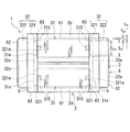
図1〜図3を参照して、実施形態1のリアクトル1を説明する。
以下の説明では、リアクトル1における設置対象に接する設置側を下側、その対向側を上側として説明する。図2は、紙面の下側がリアクトル1の設置側である場合を例示する。図2は、巻回部2aをその軸方向に平行な平面で切断した縦断面を示し、内側樹脂部61を露出させた状態を示す。また、図2の一点鎖線円内は、内コア片31と外コア片32との接続箇所近傍を拡大して示すと共に、樹脂モールド部6、介在部材5を二点鎖線で仮想的に示す。
[Embodiment 1]
The reactor 1 of the first embodiment will be described with reference to FIGS. 1 to 3.
In the following description, the installation side in contact with the installation target in the reactor 1 will be described as the lower side, and the opposite side thereof will be described as the upper side. FIG. 2 illustrates a case where the lower side of the paper surface is the installation side of the reactor 1. FIG. 2 shows a vertical cross section of the winding
〈概要〉
実施形態1のリアクトル1は、図1に示すように、コイル2と、閉磁路を形成する磁性コア3と、樹脂モールド部6とを備える。この例では、コイル2は一対の巻回部2a,2bを有する。各巻回部2a,2bは、各軸が平行するように横並びに配置される。磁性コア3は、巻回部2a,2b内に配置される内コア片31,31と、巻回部2a,2bから露出される部分(大面積部322,322)を含む二つの外コア片32,32とを備える。樹脂モールド部6は、巻回部2a,2bと磁性コア3(ここでは内コア片31,31)との間にそれぞれ介在される内側樹脂部61,61を含む。樹脂モールド部6は、各巻回部2a,2bの外周面を覆わず露出させる。巻回部2a,2bの内外に配置される磁性コア3は、巻回部2a,2bに沿って横並びされる内コア片31,31を挟むように外コア片32,32が配置されて、環状に組み付けられる。このようなリアクトル1は、代表的には、コンバータケース等の設置対象(図示せず)に取り付けられて使用される。
<Overview>
As shown in FIG. 1, the reactor 1 of the first embodiment includes a
特に、実施形態1のリアクトル1では、外コア片32において内コア片31との接続箇所として、相対的に細い部分(小面積部321)を含む。樹脂モールド部6は、内コア片31と局所的に細い小面積部321との接続箇所の外周を覆う肉厚部63を含む。外コア片32の小面積部321が局所的に細いことで、樹脂モールド部6の形成前には、図2の一点鎖線円内に拡大して示すように両コア片31,32の接続箇所における小面積部321の外周に、巻回部2a(又は2b)と内コア片31との間の筒状隙間g31よりも大きい空間(導入空間g321)を形成する。更に、外コア片32は、内コア片31の比透磁率よりも大きい比透磁率を有する。このようなリアクトル1は、導入空間g321を経て、筒状隙間g31にモールド原料を導入し易く樹脂モールド部6を形成し易い上に、肉厚部63によって両コア片31,32の接続強度に優れつつ、両コア片31,32間での漏れ磁束を低減できる。
以下、構成要素ごとに詳細に説明する。
In particular, in the reactor 1 of the first embodiment, the
Hereinafter, each component will be described in detail.
〈コイル〉
この例のコイル2は、巻線が螺旋状に巻回されてなる筒状の巻回部2a,2bを備える。横並びされる一対の巻回部2a,2bを備えるコイル2として、以下の形態が挙げられる。
(α)1本の連続する巻線から形成される巻回部2a,2bと、巻回部2a,2b間に渡される巻線の一部からなり、巻回部2a,2bを連結する連結部とを備える形態。
(β)独立した2本の巻線によってそれぞれ形成される巻回部2a,2bと、巻回部2a,2bから引き出される巻線の両端部のうち、一方の端部同士が溶接や圧着等によって接合されてなる接合部とを備える形態。
いずれの形態も、各巻回部2a,2bから引き出される巻線の端部((β)では他方の端部)は、電源等の外部装置が接続される接続箇所として利用される。
<coil>
The
(Α) A connection consisting of winding
(Β) Of the winding
In either form, the end of the winding drawn from the winding
巻線は、銅等からなる導体線と、ポリアミドイミド等の樹脂からなり、導体線の外周を覆う絶縁被覆とを備える被覆線が挙げられる。この例の巻回部2a,2bは、被覆平角線からなる巻線をエッジワイズ巻して形成された四角筒状のエッジワイズコイルであり、形状・巻回方向・ターン数等の仕様を同一とする。巻線や巻回部2a,2bの形状、大きさ等は適宜選択できる。例えば、巻線を被覆丸線としたり、巻回部2a,2bの形状を円筒状、楕円状やレーストラック状等の角部を有しない筒状としたりすることが挙げられる。また、各巻回部2a,2bの仕様を異ならせることもできる。
Examples of the winding include a coated wire having a conductor wire made of copper or the like and an insulating coating made of a resin such as polyamide-imide and covering the outer periphery of the conductor wire. The winding
実施形態1のリアクトル1では、巻回部2a,2bの外周面の全体が樹脂モールド部6に覆われず露出される。一方、巻回部2a,2b内には樹脂モールド部6の一部である内側樹脂部61が介在し、巻回部2a,2bの内周面は樹脂モールド部6に覆われる。
In the reactor 1 of the first embodiment, the entire outer peripheral surface of the winding
〈磁性コア〉
《概要》
この例の磁性コア3は、上述の四つのコア片31,31、32,32が環状に組み付けられた状態で、その外周が樹脂モールド部6によって覆われることで一体に保持されると共に、コア片間に磁気ギャップを実質的に含まないギャップレス構造である。
<Magnetic core>
"Overview"
The
実施形態1のリアクトル1では、外コア片32の磁路断面積がその全長に亘って一様ではなく部分的に異なる。具体的には、外コア片32は、小面積部321と大面積部322とを備える。図3に示すように、小面積部321は、内コア片31の端面31eが接続される接続面321eを有する。この接続面321eの面積S321(ここでは磁路断面積にも相当)は、内コア片31の端面31eの面積S31(ここでは磁路断面積にも相当)よりも小さい(図1,図2も参照)。大面積部322は、内コア片31の端面31eの面積S31よりも大きな磁路断面積S32を有する。外コア片32は、両部321,322が一体に成形されて段差形状を有する。この例では、小面積部321は、内コア片31の軸上に並ぶように配置され、大面積部322は、内コア片31に接続されず、横並びされる二つの小面積部321,321を連結する(図1)。
In the reactor 1 of the first embodiment, the magnetic path cross-sectional area of the
コイル2と磁性コア3とを組み付けた状態では、内コア片31,31は巻回部2a,2b内に配置され、外コア片32,32の大面積部322,322は巻回部2a,2bから露出される。この例では、外コア片32の小面積部321は巻回部2a(同)から露出され、巻回部2a(又は2b)の端面から突出状態で配置される(図2)。この組付状態では、図2の一点鎖線円内に示すように、内コア片31の端面31eと小面積部321の外周面と大面積部322の内端面32eとによって溝が形成される。この例では、小面積部321の外周に沿って連続する環状の溝が形成される。この環状の溝を樹脂モールド部6の肉厚部63の形成箇所とする。
以下、内コア片31、外コア片32を順に説明する。
In the state where the
Hereinafter, the
《内コア片》
この例では、磁性コア3において巻回部2a内に配置される部分及び巻回部2b内に配置される部分はいずれも、主として一つの柱状の内コア片31で構成される(図1)。一つの内コア片31において一方の端面31eは、一方の外コア片32の接続面321eに接合され、他方の端面31eは、他方の外コア片32の接続面321eに接合される(図2)。なお、この例では、両コア片31,32同士の継ぎ目箇所には、後述する介在部材5が配置される。
《Inner core piece》
In this example, in the
この例の内コア片31,31はいずれも同一形状、同一の大きさであり、図3に示すように直方体状である。内コア片31の形状は適宜変更できる。例えば、内コア片31を円柱状、六角柱等の多角柱状等とすることが挙げられる。角柱等とする場合に内コア片31の角部をC面取り又は図3に示すようにR面取りされたような形状とすることが挙げられる。角部が丸められることで、欠け難く強度に優れる上に、軽量化、内側樹脂部61との接触面積の増大を図ることができる。
The
この例の内コア片31は、導入溝315(詳細は後述)の形成領域を除いて、その全長に亘って所定の磁路断面積S31を有する。そのため、磁性コア3は、磁路断面積S31を有する部分を十分に確保して、所定の磁気特性を有することができる。図3では、内コア片31の磁路断面積S31、及び外コア片32の小面積部321の面積S321、大面積部322の磁路断面積S32を仮想的に示す。
The
《外コア片》
この例では、磁性コア3において巻回部2a外に配置される部分及び巻回部2b外に配置される部分はいずれも、主として一つの柱状の外コア片32で構成される(図1)。
《Outer core piece》
In this example, both the portion of the
この例の外コア片32,32はいずれも同一形状、同一の大きさであり、図3に示すように相対的に大きな直方体の一面に、相対的に小さく薄い直方体が二つ並んで配置されたような形状であり、平面視でU字状である(図1)。詳しくは、一つの外コア片32は、直方体状の大面積部322と、大面積部322において巻回部2b,2bの端面に対向して配置される平坦な内端面32eから、巻回部2b,2b側に向かって突出する直方体状(板状)の小面積部321,321とを備える。一つの外コア片32において各小面積部321,321は、内端面32eにおける巻回部2a,2bに沿って並ぶ内コア片31,31の端面31e,31eが配置される箇所に対応して設けられる。
The
この例の小面積部321は、内コア片31の端面31eに接続される接続面321eを含めて、その全長に亘って一様な磁路断面積S321を有する柱状体である。接続面321eの面積S321は、内コア片31の端面31eの面積S31よりも小さい(S321<S31)。両面積S321,S31が異なることで、両者の輪郭寸法も異なる。この寸法差によって生じる段差部分に形成される空間(導入空間g321)を、樹脂モールド部6の形成時に巻回部2a,2bと内コア片31,31との間の筒状隙間g31にモールド原料を導く案内箇所として利用する。かつ、導入空間g321を肉厚部63の形成箇所に利用する(図2)。
The
上述の段差部分の大きさを調整することで、筒状隙間g31へのモールド原料の導入容易性や肉厚部63の大きさを調整できる。例えば、上記段差部分の段差高さが大きいほど、又は上記段差部分の幅が広いほど、導入空間g321を大きくでき、導入容易性を高めたり、肉厚部63を厚くしたり広幅にしたりすることができる。また、小面積部321の外形や大面積部322の内端面32eに対する小面積部321の形成位置等によって上記段差部分の形成長さが異なり、導入空間g321や肉厚部63の周長も異なる。例えば、小面積部321の外周面の一部が内コア片31の外周面と面一になるように小面積部321の形成位置が調整されている場合、小面積部321の外周面の一部にのみ段差を設けられる。この例のように小面積部321と内コア片31とが同軸に並ぶ相似形状とすれば、小面積部321の全周に亘って段差を設けられる。その結果、一様な厚さの導入空間g321や肉厚部63を環状に設けられる。より厚く、幅広で環状の肉厚部63を備えると、両コア片31,32の接続強度をより高められて好ましい。なお、段差高さとは、巻回部2a,2bの軸方向に直交する方向の大きさとする。段差部分の幅とは、巻回部2a,2bの軸方向に沿った大きさとする。上記幅は、ここでは小面積部321における大面積部322の内端面32eからの突出高さに相当する。
By adjusting the size of the step portion described above, the ease of introducing the mold raw material into the tubular gap g 31 and the size of the
上述の段差部分の大きさに関して、小面積部321の磁路断面積S321が小さいほど、段差高さを大きくできる。又は、小面積部321の突出高さが大きいほど、段差部分の幅を広くできる。しかし、磁路断面積S321が小さ過ぎたり、突出高さが大き過ぎたりすると、磁性コア3において磁路断面積S31よりも小さい磁路断面積S321を有する部分の割合が多くなるため、磁気飽和し易くなったり、小面積部321からの漏れ磁束が多くなったりし得る。導入容易性、接続強度、磁気飽和や漏れ磁束等の磁気特性等を考慮すると、小面積部321の磁路断面積S321は、内コア片31の磁路断面積S31の60%以上100%未満、更に65%以上98%以下、70%以上95%以下程度とすることが挙げられる。又は、段差高さは、0.1mm以上2mm以下、更に0.5mm以上1.5mm以下、1.2mm以下程度とすることが挙げられる。また、段差部分の幅(突出高さ)は、巻回部2a,2bの長さの1%以上35%以下、更に5%以上20%以下、15%以下程度とすることが挙げられる。
Regarding the size of the above-mentioned step portion, the smaller the magnetic path cross-sectional area S 321 of the
この例の小面積部321,321は、コイル2と磁性コア3とを組み付けた状態において、巻回部2a,2bから露出される。即ち、この例の外コア片32は、その全体が巻回部2a,2bから露出される。なお、内コア片31の長さや小面積部321の長さを調整して、小面積部321,321の少なくとも一部を巻回部2a,2b内に配置することもできる。
The
この例の小面積部321は、直方体状とするが適宜変更できる。例えば、小面積部321を円柱状、六角柱等の多角柱状等とすることが挙げられる。この例のように小面積部321がその全長に亘って一様な面積S321を有し、内コア片31の端面31eに相似形状の接続面321eを有すると、上述のように環状の導入空間g321を形成できて好ましい。
The
大面積部322は、内コア片31の磁路断面積S31よりも大きな磁路断面積S32を有する柱状体である(S31<S32)。即ち、磁性コア3は、面積についてS321<S31<S32を満たす。なお、外コア片32は、小面積部321と大面積部322とを有すれば、磁路断面積S31を有する部分を含むことができる。
Large-
《組付状態》
内コア片31の端面31eと外コア片32の小面積部321の接続面321eとを接続して、磁性コア3を組み付けた状態で外コア片32の外端面32o(図1)から巻回部2a,2bの軸方向にみると(正面視すると)、両内コア片31,31の端面31e,31eはいずれも、外コア片32に重複してみえない。この例の外コア片32は、内端面32eの面積が内コア片31の端面31eの合計面積(2×S31)よりも大きく、外コア片32の外周面(図1では上下の面)と両内コア片31,31の外周面とが面一になるように組み付けられているからである。
《Assembled state》
The
但し、樹脂モールド部6の形成前において、外コア片32の小面積部321の外周には筒状隙間g31よりも大きな導入空間g321を形成できる。この例では、小面積部321,321が巻回部2a,2bから露出されるため、導入空間g321を巻回部2a,2bの端面と外コア片32の大面積部322の内端面32eとの間に形成できる(図2)。従って、外コア片32の外端面32o(図1)側からモールド原料を供給すると、大面積部322の外周面を経て導入空間g321にモールド原料を導入できる。更に、導入空間g321を経て筒状隙間g31にモールド原料を導入できる。この例では小面積部321の外周の全周から、筒状隙間g31にモールド原料を導入できる。なお、外コア片32において、小面積部321の外周面の全周を内コア片31の外周面とは面一とせず、かつ、小面積部321の外周面の一部と大面積部322の外周面の一部とが面一になるように成形すれば(図2では大面積部322の上面を下方に下げた状態にすれば)、外コア片32から導入空間g312にモールド原料をより流し易い。
However, before the formation of the
外コア片32の小面積部321の具備に加えて、内コア片31には導入溝315を備えることができる。導入溝315は、内コア片31の端面31eにおいて小面積部321との間で段差部分をなす領域と、外周面とに開口して、導入空間g321と筒状隙間g31との双方に連通する空間を形成する。そのため、コイル2を露出させつつ磁性コア3を覆う樹脂モールド部6を形成する際、外コア片32側からコイル2側にモールド原料を供給すれば、導入空間g321から導入溝315を経て筒状隙間g31にモールド原料を容易に導入できる(図2の一点鎖線円内も参照)。更に、樹脂モールド部6において導入溝315を覆う箇所は、内コア片31における導入溝315の形成領域以外の領域を覆う箇所の厚さt61よりも厚く形成される上に、肉厚部63に連続する。従って、樹脂モールド部6は両コア片31,32の接続箇所近傍に局所的に厚い箇所をより多く備えられ、両コア片31,32の接続強度をより高められる。
In addition to the
導入溝315の形状(開口形状、断面形状等)、大きさ(深さ、開口幅、長さ(内コア片31の軸方向に沿った大きさ)等)、個数、形成位置等は適宜選択できる。導入溝315が大きいほど、又は個数が多いほど、モールド原料の導入容易性や接続強度を高められる。しかし、導入溝315が大き過ぎたり、個数が多過ぎたりすると、磁路断面積S31を有する部分の割合が少なくなり、磁気飽和し易くなったり、導入溝315近傍からの漏れ磁束が多くなったりし得る。導入容易性、接続強度、磁気飽和や漏れ磁束等の磁気特性等を考慮すると、内コア片31において導入溝315の形成領域の磁路断面積がS321以上S31以下を満たすように、導入溝315の大きさが調整されていることが挙げられる。導入溝315の長さは、例えばコイル2の5ターン以下の長さ、更に2ターン以下の長さ程度が挙げられる。この例のように小面積部321の外周面の全周が内コア片31の外周面に面一でなければ、導入溝315を内コア片31の端面31eの任意の位置に開口でき、形成位置の自由度が大きい。
The shape (opening shape, cross-sectional shape, etc.), size (depth, opening width, length (size along the axial direction of the inner core piece 31), etc.), number, formation position, etc. of the
導入溝315の開口部は、内コア片31の外周面のうち、隣り合う内コア片31,31同士が対向する領域(以下、内側領域と呼ぶ)から離れた領域に設けられることが好ましい。上記の内側領域は、隣り合う内コア片31,31において互いに離れる側に配置される領域に比較して磁束が通過し易い。このような内側領域に開口する導入溝315を備えると、導入溝315近傍からの漏れ磁束の増大を招き得るからである。
The opening of the
この例では、一つの内コア片31の各端部において、上述の内側領域に相当する面(図1では隣り合う内コア片31,31において対向配置される面、図3では紙面手前側の面)を除く三面(図2では上下面、及び紙面手前側の面)にそれぞれ開口する導入溝315を備える場合を例示する。つまり、一つの内コア片31は、その両端部の合計で六つの導入溝315を備える。各導入溝315は同一形状、同一の大きさであり、開口形状が長方形状であり、内コア片31の外周面に概ね平行な溝底面と、この溝底面に交差し、溝底面から上記外周面に至る傾斜面とを備える場合を例示する。傾斜面は、端面31eから離れるに従って溝深さが浅くなるように傾斜する。そのため、傾斜面は、導入溝315から筒状隙間g31にモールド原料をより流れ易くすることに寄与する。
In this example, at each end of one
この例の外コア片32,32は同一形状、同一の大きさであり、同じ金型でコア片を製造できる上に、樹脂モールド部6の形成時に条件の調整等が行い易い。これらの点から、製造性に優れる。その他、各外コア片32,32で小面積部321の形状や大きさを異ならせたり、又は一つの外コア片32について小面積部321,321の形状や大きさを異ならせたりすることができる。例えば、一方の外コア片32のみに小面積部321,321を備え、他方の外コア片32には小面積部321を備えない形態が挙げられる。
The
《特性》
外コア片32の比透磁率は、内コア片31の比透磁率よりも大きい。そのため、外コア片32における内コア片31との接続箇所をなす小面積部321の面積S321が、内コア片31の磁路断面積S31よりも小さくても、両コア片31,32間での漏れ磁束を低減できる。このような比透磁率が異なるコア片31,32を備えるリアクトル1は、上記漏れ磁束に起因する損失を低減でき、低損失である。
"Characteristic"
The relative magnetic permeability of the
ここでの比透磁率は以下のように求める。各コア片31,32と同様の組成からなるリング状の測定試料(外径34mm、内径20mm、厚さ5mm)を作製し、測定試料に一次側:300巻き、二次側:20巻きの巻線を施し、B−H初磁化曲線をH=0(Oe)〜100(Oe)の範囲で測定する。得られたB−H初磁化曲線のB/Hの最大値を求め、この最大値を比透磁率とする。ここでの磁化曲線とは、いわゆる直流磁化曲線である。
The relative magnetic permeability here is calculated as follows. A ring-shaped measurement sample (outer diameter 34 mm, inner diameter 20 mm,
外コア片32の比透磁率が内コア片31の比透磁率よりも大きく、かつ両比透磁率の差が大きいほど、特に外コア片32の比透磁率が内コア片31の比透磁率の2倍以上であると、両コア片31,32間での漏れ磁束をより確実に低減できる。上記差がより大きい場合、例えば外コア片32の比透磁率が内コア片31の比透磁率の2.5倍以上、更に3倍以上、5倍以上、10倍以上であれば、上記漏れ磁束をより一層低減し易く、好ましくは上記漏れ磁束を実質的に無くすことができる。
The greater the relative magnetic permeability of the
内コア片31の比透磁率は、例えば5以上50以下が挙げられる。内コア片31の比透磁率は、10以上45以下、更に40以下、35以下、30以下とより低くすることができる。このような低透磁率の内コア片31を備える磁性コア3は、磁気飽和し難いため、磁気ギャップを有さないギャップレス構造とすることができる。ギャップレス構造の磁性コア3は、磁気ギャップに起因する漏れ磁束が実質的に生じないため、筒状隙間g31を小さくし易く、より小型なリアクトル1とすることができる。筒状隙間g31が小さくても、上述のように導入空間g321を形成できるため、モールド原料を筒状隙間g31に導入し易く、樹脂モールド部6を形成し易い。
The relative magnetic permeability of the
外コア片32の比透磁率は、例えば50以上500以下が挙げられる。外コア片32の比透磁率は、80以上、更に100以上(内コア片31の比透磁率が50である場合の2倍以上)、150以上、180以上とより高くすることができる。このような高透磁率の外コア片32は、内コア片31の比透磁率との差を大きくし易い。例えば、外コア片32の比透磁率を内コア片31の比透磁率の2倍以上とすることができる。そのため、外コア片32の小面積部321をより小さくしても(細くしても)、両コア片31,32間での漏れ磁束を低減できる。また、小面積部321がより細ければ、導入空間g321をより大きくできるため、モールド原料を筒状隙間g31に更に導入し易い。
The relative magnetic permeability of the
《材質》
磁性コア3を構成する内コア片31、外コア片32は、軟磁性材料、例えば鉄や鉄合金(Fe−Si合金、Fe−Ni合金等)といった軟磁性金属等を含む成形体が挙げられる。コア片の具体例として、軟磁性材料からなる粉末や更に絶縁被覆を備える被覆粉末といった磁性粉末と樹脂とを含む複合材料の成形体からなる樹脂コア片、上記磁性粉末が圧縮成形された圧粉成形体からなる圧粉コア片、軟磁性材料の焼結体からなるフェライトコア片、電磁鋼板といった軟磁性金属板が積層された積層体からなる鋼板コア片等が挙げられる。磁性コア3は、例えば、上述の樹脂コア片、圧粉コア片、フェライトコア片、及び鋼板コア片からなる群から選択される複数種のコア片を含む混合形態とすると、比透磁率が異なる内コア片31及び外コア片32を容易に含むことができる。その他、磁性コア3は、コア片として樹脂コア片のみを備える形態とすることが挙げられる。樹脂コア片では磁性粉末の組成や含有量の多寡によって比透磁率を容易に異ならせることができる。内コア片31及び外コア片32が所定の比透磁率を有するように、磁性粉末の組成や含有量を調整するとよい。
《Material》
Examples of the
樹脂コア片を構成する上述の複合材料中の磁性粉末の含有量は、30体積%以上80体積%以下、樹脂の含有量は10体積%以上70体積%以下が挙げられる。飽和磁束密度や放熱性の向上の観点から、磁性粉末の含有量を50体積%以上、更に55体積%以上、60体積%以上とすることができる。製造過程での流動性の向上の観点から、磁性粉末の含有量を75体積%以下、更に70体積%以下、樹脂の含有量を30体積%超とすることができる。 The content of the magnetic powder in the above-mentioned composite material constituting the resin core piece is 30% by volume or more and 80% by volume or less, and the resin content is 10% by volume or more and 70% by volume or less. From the viewpoint of improving the saturation magnetic flux density and heat dissipation, the content of the magnetic powder can be 50% by volume or more, further 55% by volume or more, and 60% by volume or more. From the viewpoint of improving the fluidity in the manufacturing process, the content of the magnetic powder can be 75% by volume or less, further 70% by volume or less, and the resin content can be more than 30% by volume.
上述の複合材料中の樹脂は、熱硬化性樹脂、熱可塑性樹脂、常温硬化性樹脂、低温硬化性樹脂等が挙げられる。熱硬化性樹脂は、例えば、不飽和ポリエステル樹脂、エポキシ樹脂、ウレタン樹脂、シリコーン樹脂等が挙げられる。熱可塑性樹脂は、ポリフェニレンスルフィド(PPS)樹脂、ポリテトラフルオロエチレン(PTFE)樹脂、液晶ポリマー(LCP)、ナイロン6やナイロン66といったポリアミド(PA)樹脂、ポリブチレンテレフタレート(PBT)樹脂、アクリロニトリル・ブタジエン・スチレン(ABS)樹脂等が挙げられる。その他、不飽和ポリエステルに炭酸カルシウムやガラス繊維が混合されたBMC(Bulk molding compound)、ミラブル型シリコーンゴム、ミラブル型ウレタンゴム等も利用できる。
Examples of the resin in the above-mentioned composite material include a thermosetting resin, a thermoplastic resin, a room temperature curable resin, and a low temperature curable resin. Examples of the thermosetting resin include unsaturated polyester resin, epoxy resin, urethane resin, and silicone resin. Thermoplastic resins include polyphenylene sulfide (PPS) resin, polytetrafluoroethylene (PTFE) resin, liquid crystal polymer (LCP), polyamide (PA) resin such as
上述の複合材料は、磁性粉末及び樹脂に加えて、アルミナやシリカ等の非磁性かつ非金属粉末(フィラー)を含有すると、放熱性をより高められる。非磁性かつ非金属粉末の含有量は、0.2質量%以上20質量%以下、更に0.3質量%以上15質量%以下、0.5質量%以上10質量%以下が挙げられる。 When the above-mentioned composite material contains a non-magnetic and non-metallic powder (filler) such as alumina or silica in addition to the magnetic powder and resin, the heat dissipation property can be further enhanced. The content of the non-magnetic and non-metallic powder includes 0.2% by mass or more and 20% by mass or less, 0.3% by mass or more and 15% by mass or less, and 0.5% by mass or more and 10% by mass or less.
上述の複合材料の成形体は、射出成形や注型成形等の適宜な成形方法によって製造できる。樹脂コア片は、製造過程で磁性粉末の充填率を低く調整すれば、比透磁率を小さくし易い。例えば、樹脂コア片の比透磁率は5以上50以下が挙げられる。 The composite material molded body described above can be manufactured by an appropriate molding method such as injection molding or casting molding. If the filling rate of the magnetic powder of the resin core piece is adjusted to be low in the manufacturing process, the relative magnetic permeability can be easily reduced. For example, the relative magnetic permeability of the resin core piece is 5 or more and 50 or less.
上述の圧粉成形体は、代表的には、磁性粉末とバインダーとを含む混合粉末を所定の形状に圧縮成形したもの、更に成形後に熱処理を施したものが挙げられる。バインダーは樹脂等を利用でき、その含有量は30体積%以下程度が挙げられる。熱処理を施すと、バインダーが消失したり、熱変性物になったりする。圧粉成形体は、複合材料の成形体よりも磁性粉末の含有量を高め易く(例えば80体積%超、更に85体積%以上)、飽和磁束密度や比透磁率がより高いコア片を得易い。例えば、圧粉コア片の比透磁率は50以上500以下が挙げられる。 Typical examples of the above-mentioned powder compact have been one in which a mixed powder containing a magnetic powder and a binder is compression-molded into a predetermined shape, and one in which heat treatment is performed after molding. A resin or the like can be used as the binder, and the content thereof is about 30% by volume or less. When heat treatment is applied, the binder disappears or becomes a heat-denatured product. The powder compact has a higher content of magnetic powder than a composite molded body (for example, more than 80% by volume and more than 85% by volume), and it is easy to obtain a core piece having a higher saturation magnetic flux density and specific magnetic permeability. .. For example, the relative magnetic permeability of the dust core piece is 50 or more and 500 or less.
この例の内コア片31は樹脂コア片であり、外コア片32は圧粉コア片である。また、この例では、内コア片31の比透磁率は5以上50以下であり、外コア片32の比透磁率は50以上500以下であり、かつ内コア片31の比透磁率の2倍以上である。
The
内コア片31を樹脂コア片とする場合、外コア片32において小面積部321の接続面321eの面積S321は、内コア片31の端面31eの面積S31と内コア片31における磁性粉末の充填率αとの積(S31×α)で求められる値以上であることが挙げられる。ここで、内コア片31が樹脂コア片である場合、内コア片31の端面31eに存在する磁性粉末が実質的に磁路として機能する。つまり、端面31eの面積S31を見かけの磁路面積、上記積値(S31×α)を実効的な磁路面積と見做すことができる。小面積部321の接続面321eの面積S321が上記積値(S31×α)以上であれば、接続面321eは、内コア片31の実効的な磁路面積以上を有するため、両コア片31,32間での漏れ磁束をより確実に低減できつつ、所定の特性を有するリアクトル1とすることができる。本例の面積S321は上記積値(S31×α)以上である。
When the
樹脂コア片における磁性粉末の充填率α(%)は、簡易的には、樹脂コア片の断面における磁性粉末の合計面積割合を利用することが挙げられる。合計面積割合は、例えば、以下のように求める。樹脂コア片の断面を顕微鏡観察して、この断面の面積S又は所定の大きさの視野面積Sにおける磁性粉末を抽出して、磁性粉末の合計面積Spを求める。(Sp/S)×100(%)を合計面積割合とする。厳密には、樹脂コア片の樹脂等を除去して磁性粉末を抽出し、樹脂コア片の体積Vと、抽出した磁性粉末の体積Vpとから、充填率α=(Vp/V)×100(%)を求めることが挙げられる。 As the filling rate α (%) of the magnetic powder in the resin core piece, it is possible to simply use the total area ratio of the magnetic powder in the cross section of the resin core piece. The total area ratio is calculated as follows, for example. The cross section of the resin core piece is observed under a microscope, and the magnetic powder in the area S of this cross section or the visual field area S of a predetermined size is extracted to obtain the total area Sp of the magnetic powder. Let (Sp / S) × 100 (%) be the total area ratio. Strictly speaking, the resin and the like of the resin core piece are removed to extract the magnetic powder, and the filling rate α = (Vp / V) × 100 (from the volume V of the resin core piece and the volume Vp of the extracted magnetic powder). %) Can be found.
〈介在部材〉
この例のリアクトル1は、更に、コイル2と磁性コア3との間に介在される介在部材5を備える。介在部材5は、代表的には絶縁材料からなり、コイル2と磁性コア3との間の絶縁部材や、巻回部2a,2bに対する内コア片31、外コア片32の位置決め部材等として機能する。この例の介在部材5は、内コア片31と外コア片32との継ぎ目箇所及びその近傍が配置される長方形の枠状のものであり、樹脂モールド部6の形成時、モールド原料の流路を形成する部材としても機能する。
<Intervening member>
The reactor 1 of this example further includes an intervening
介在部材5は、例えば、以下の貫通孔と、支持部と、コイル溝部と、コア溝部とを備えるものが挙げられる(類似の形状として特許文献1の外側介在部52参照)。貫通孔は、介在部材5において外コア片32が配置される側(以下、外コア側と呼ぶ)から巻回部2a,2bが配置される側(以下、コイル側と呼ぶ)に貫通し、内コア片31,31が挿通される。この例では、コア片32の小面積部321も貫通孔を挿通して、貫通孔内で内コア片31の端面31eと小面積部321の接続面321eとが接続される。支持部は、貫通孔を形成する内周面から部分的に突出して内コア片31の一部(この例では四つの角部)を支持する。コイル溝部は、介在部材5のコイル側に設けられ、各巻回部2a,2bの端面及びその近傍が嵌め込まれる。コア溝部は、介在部材5の外コア側に設けられ、外コア片32の内端面32e及びその近傍が嵌め込まれる。
Examples of the intervening
巻回部2a,2bがコイル溝部に嵌め込まれ、内コア片31,31が各貫通孔に挿通されて、端面31e,31eと、コア溝部に嵌め込まれた外コア片32の小面積部321の内端面32eとが当接された状態において、モールド原料の流路が設けられるように介在部材5の形状や大きさを調整する。モールド原料の流路を設けるには、例えば、各内コア片31,31における支持部に支持されていない箇所や外コア片32の小面積部321と貫通孔の内周面との間や、外コア片32の大面積部322とコア溝部との間等に隙間を設けることが挙げられる。また、このモールド原料の流路は、巻回部2a,2bの外周面にモールド原料が漏出しないように設ける。介在部材5は、上述の機能を有すれば、形状や大きさ等を適宜選択でき、公知の構成を参照できる。
The winding
この例では、内コア片31の一部を支持部によって支持すると共にコイル溝部の内面によって巻回部2a,2bを支持することで、巻回部2a(又は2b)と内コア片31との間に筒状隙間g31を形成するように貫通孔、コイル溝部が設けられている。また、外コア片32の内端面32eの一部をコア溝部の溝底面で支持することで、内端面32eから突出する小面積部321の外周面と貫通孔の内周面の一部との間に導入空間g321を形成すると共に、大面積部322の外周面とコア溝部の内周面との間に隙間を形成するように貫通孔、コア溝部が設けられている。このような貫通孔やコイル溝部、コア溝部を備える介在部材5と、コイル2と、磁性コア3とが組み付けられた状態では、上記外コア片32の周囲の隙間から導入空間g312を経て筒状隙間g31に連通する空間を設けられる(同)。この連通空間をモールド原料の流路に利用する。
In this example, a part of the
介在部材5の構成材料は、各種の樹脂といった絶縁材料が挙げられる。例えば、樹脂コア片を構成する複合材料の項で説明した各種の熱可塑性樹脂、熱硬化性樹脂等が挙げられる。介在部材5は、射出成形等の公知の成形方法によって製造できる。
Examples of the constituent material of the intervening
〈樹脂モールド部〉
《概要》
樹脂モールド部6は、磁性コア3をなす少なくとも一つのコア片の外周を覆うことで、コア片を外部環境から保護したり、機械的に保護したり、コア片とコイル2や周囲部品との間の絶縁性を高めたりする機能を有する。かつ、樹脂モールド部6は、巻回部2a,2bの外周を覆わず露出させることで、例えば巻回部2a,2bを液体冷媒等の冷却媒体に直接接触させられて、放熱性を高められる。
<Resin mold part>
"Overview"
The
樹脂モールド部6は、内コア片31,31における巻回部2a,2b内に収納される部分の外周を覆う内側樹脂部61,61に加えて、内コア片31と外コア片32との接続箇所を覆う肉厚部63を備える。この例の樹脂モールド部6は、更に外コア片32,32の外周を覆う外側樹脂部62,62を備え、これらが連続して形成された一体物であると共に、磁性コア3と介在部材5との組物を一体に保持する。
以下、内側樹脂部61、外側樹脂部62、肉厚部63を順に説明する。
The
Hereinafter, the
《内側樹脂部》
この例の内側樹脂部61は、巻回部2a(又は2b)の内周面と内コア片31の外周面との間の筒状隙間g31(ここでは四角筒状の空間)に樹脂モールド部6の構成樹脂が充填されてなる筒状体である。この例では、内コア片31の導入溝315を覆う部分を除いて、内側樹脂部61の全長に亘って概ね一様な厚さt61(図1)を有する。本例のようにギャップレス構造の磁性コア3とすれば、筒状隙間g31を小さくでき、筒状隙間g31の大きさに応じて内側樹脂部61の厚さt61を薄くできる(図2)。内側樹脂部61の厚さt61は適宜選択でき、例えば0.1mm以上4mm以下、更に0.3mm以上3mm以下、更には2.5mm以下、2mm以下、1.5mm以下程度が挙げられる。内側樹脂部61において導入溝315を覆う部分の厚さは、上述の厚さt61に加えて、導入溝315の深さ分だけ厚い。
《Inner resin part》
The
《外側樹脂部》
この例の外側樹脂部62は、外コア片32の外周面のうち、内コア片31,31が接続される小面積部321及びその近傍を除いて実質的に全体を外コア片32に沿って覆い、概ね一様な厚さを有する。外側樹脂部62における外コア片32の被覆領域、厚さ等は適宜選択できる。外側樹脂部62の厚さは例えば内側樹脂部61の厚さt61と等しくすることもできるし、異ならせることもできる。
<< Outer resin part >>
The
《肉厚部》
この例の肉厚部63は、内側樹脂部61と外側樹脂部62との間に介在し、内コア片31の端面31eと外コア片32の小面積部321の接続面321eとの当接部分を含む両コア片31,32の接続箇所を覆う。肉厚部63は、外コア片32の小面積部321と内コア片31の端面31eとの段差部分に樹脂モールド部6の構成樹脂が充填されてなるため、肉厚部63の厚さt63は、内コア片31を覆う箇所の厚さ(ここでは内側樹脂部61の厚さt61)よりも上述の段差高さ分だけ厚い(図1)。肉厚部63の厚さt63が厚いほど、両コア片31,32の接続強度を高め易く、樹脂モールド部6によって一体に保持される磁性コア3について、一体物としての強度を高め易い。肉厚部63の厚さt63は、内側樹脂部61の厚さt61と上述の段差高さとの合計値に相当することから、上記厚さt61及び上記段差高さの少なくとも一方をより大きくすることで厚くすることができ、上記接続強度をより高められる。内側樹脂部61の厚さt61が厚いほど、コア片の外部環境からの保護、機械的保護、絶縁性の確保等の効果を得易いものの、樹脂モールド部6の重量の増大や大型化、ひいてはリアクトル1の重量の増大や大型化を招く。上述の段差高さが大きいほど、上述の磁気特性の低下等を招き得る。従って、上述の厚さt61,t63は、重量や寸法、磁気特性、強度等を考慮して選択することが挙げられる。
《Thick part》
The
《構成材料》
樹脂モールド部6の構成材料は、各種の樹脂、例えば、PPS樹脂、PTFE樹脂、LCP、PA樹脂、PBT樹脂等の熱可塑性樹脂が挙げられる。上記構成材料を、これらの樹脂に熱伝導性に優れる上述のフィラー等を含有する複合樹脂とすれば、放熱性に優れる樹脂モールド部6とすることができる。樹脂モールド部6の構成樹脂と介在部材5の構成樹脂とを同じ樹脂とすれば、両者の接合性に優れる上に、両者の熱膨張係数が同じであるため、熱応力による剥離や割れ等を抑制できる。樹脂モールド部6の成形には、射出成形等が利用できる。
<< constituent materials >>
Examples of the constituent material of the
《リアクトルの製造方法》
実施形態1のリアクトル1は、例えば、コイル2と磁性コア3をなすコア片(ここでは二つの内コア片31,31及び二つの外コア片32,32)と介在部材5とを組み付け、この組物を樹脂モールド部6の成形金型(図示せず)に収納し、モールド原料によってコア片を被覆することで製造できる。
<< Manufacturing method of reactor >>
In the reactor 1 of the first embodiment, for example, a core piece (here, two
この例では、介在部材5のコイル側に巻回部2a,2bを配置したり、各貫通孔に内コア片31,31や小面積部321を挿通したり、コア側に外コア片32,32を配置したりすることで、上述の組物を容易に組み付けられる。樹脂モールド部6の形成前の上記組物は、上述のように外コア片32側から巻回部2a,2b内に連通する空間が設けられており、この空間をモールド原料の流路として好適に利用できる。
In this example, the winding
上述の組物を成形金型に収納し、モールド原料を充填する。一方の外コア片32から他方の外コア片32に向かう一方向の充填や、各外コア片32,32から巻回部2a,2b内に向かう二方向の充填が利用できる。いずれの充填方法においても、外コア片32の外端面32oをモールド原料の充填開始位置とし、外コア片32を経て巻回部2a,2bの各端部からモールド原料を充填する。モールド原料は、外コア片32の外周面を経て導入空間g321に流れ、更に導入空間g321を経て筒状隙間g31に流入する。いずれの充填方法においても、本例のように両外コア片32,32が小面積部321,321を備えると、リアクトル1の製造性に優れる。磁性コア3を組み付け易い上に、導入空間g312によって脱気等を行い易く、モールド原料をより導入し易いからである。一方向の充填を行う場合、一方の外コア片32のみに小面積部321,321を備え、この外コア片32の外端面320を充填開始位置に配置することができる。一方向の充填を行う場合に両外コア片32,32にそれぞれ、小面積部321,321を備えることもできる。
The above-mentioned assembly is stored in a molding die and filled with a molding raw material. One-way filling from one
《用途》
実施形態1のリアクトル1は、電圧の昇圧動作や降圧動作を行う回路の部品、例えば種々のコンバータや電力変換装置の構成部品等に利用できる。コンバータの一例として、ハイブリッド自動車、プラグインハイブリッド自動車、電気自動車、燃料電池自動車等の車両に搭載される車載用コンバータ(代表的にはDC−DCコンバータ)や、空調機のコンバータ等が挙げられる。
《Use》
The reactor 1 of the first embodiment can be used as a component of a circuit that performs a voltage step-up operation or a voltage step-down operation, for example, a component of various converters or power conversion devices. Examples of converters include in-vehicle converters (typically DC-DC converters) mounted on vehicles such as hybrid vehicles, plug-in hybrid vehicles, electric vehicles, and fuel cell vehicles, converters for air conditioners, and the like.
《効果》
実施形態1のリアクトル1は、樹脂モールド部6において内コア片31と外コア片32との接続箇所を覆う位置に肉厚部63を備える。肉厚部63は、樹脂モールド部6において内コア片31を覆う内側樹脂部61の厚さt61よりも厚く割れ難い。このような肉厚部63を備える実施形態1のリアクトル1は、樹脂モールド部6によって一体に保持される磁性コア3について、一体物としての強度を向上できて、強度に優れる。コア片31,32同士を接着剤によって接続していなくても、肉厚部63を備えることで、磁性コア3を強固に一体に保持できる。この例の樹脂モールド部6は内側樹脂部61と外側樹脂部62とを含み、両者が連続して一体に形成されていることからも、磁性コア3は樹脂モールド部6によって一体物として剛性を高められる。また、リアクトル1は、肉厚部63を樹脂モールド部6に局所的に備えるため、樹脂モールド部6の全体厚さが厚い場合に比較して小型でありつつ、強度に優れる。
"effect"
The reactor 1 of the first embodiment includes a
かつ、実施形態1のリアクトル1は、外コア片32が内コア片31の磁路断面積S31よりも大きな磁路断面積S32を有する大面積部322を備えるものの、内コア片31との接続箇所に磁路断面積S31よりも小さな磁路断面積S321を有する小面積部321を備える。この小面積部321によって、筒状隙間g31の開口部近傍に導入空間g321を形成できるため、実施形態1のリアクトル1は、導入空間g321を経て筒状隙間g31にモールド原料を容易に導入でき、樹脂モールド部6を形成し易い。
Further, although the reactor 1 of the first embodiment includes a
並びに、実施形態1のリアクトル1は、外コア片32の比透磁率が内コア片31の比透磁率よりも高いため、内コア片31における外コア片32との接続箇所をなす小面積部321が内コア片31よりも細くても、両コア片31,32間での漏れ磁束を低減できる。従って、実施形態1のリアクトル1は、上記漏れ磁束に起因する損失の増大を低減でき、低損失である。
In addition, since the relative permeability of the
また、実施形態1のリアクトル1は、内側樹脂部61,61によって巻回部2a,2bと内コア片31,31との間の絶縁性を高められる上に、巻回部2a,2bが樹脂モールド部6に覆われずに露出されることで、例えば液体冷媒等の冷却媒体に直接接触できて、放熱性に優れる。特に、リアクトル1は、外コア片32が大面積部322を備えるため、外コア片が一様な磁路断面積S321を有する場合に比較して大面積部322から放熱し易かったり、大面積部322が上述の冷却媒体に接触し易かったりすることからも、放熱性に優れる。大面積部322の具備によって一様な磁路断面積S31を有する外コア片よりも表面積が大きい場合には放熱性に更に優れる。
Further, in the reactor 1 of the first embodiment, the
この例のリアクトル1は、更に、以下の効果を奏する。
(1)両コア片31,32の接続強度をより高められる上に、筒状隙間g31にモールド原料をより導入し易い。
肉厚部63及び導入空間g321が外コア片32の小面積部321の外周に沿って環状に設けられるからである。
内コア片31に複数の導入溝315を備えるからである。この例の樹脂モールド部6は、肉厚部63に連続して、導入溝315を覆う厚い樹脂部分を複数備える。
導入溝315を形成する内周面が筒状隙間g31側にモールド原料を案内する傾斜面を含むからである。
(2)より低損失なリアクトル1とすることができる。
内コア片31を比透磁率が5以上50以下の複合材料の成形体とし、外コア片32を比透磁率が50以上500以下、内コア片31の比透磁率の2倍以上の圧粉成形体とするため、ギャップレス構造の磁性コア3とすることができ、磁気ギャップに起因する損失が実質的に生じないからである。
外コア片32の小面積部321が巻回部2a(又は2b)から露出され、小面積部321からの漏れ磁束に起因する損失を低減できるからである。
(3)より小型なリアクトル1とすることができる。
ギャップレス構造であることで筒状隙間g31を小さくでき、内側樹脂部61の厚さt61を薄くできるからである。
内コア片31を複合材料の成形体とし、外コア片32を圧粉成形体とすることで、複合材料の成形体の磁性コアとする場合に比較して、磁性コア3を小型にし易いからである。
なお、筒状隙間g31が小さくても、上述のように小面積部321の周囲に導入空間g321を形成できるため、筒状隙間g31にモールド原料を導入し易く、樹脂モールド部6を形成し易い。
Reactor 1 of this example further exerts the following effects.
(1) The connection strength of both
This is because the
This is because the
This is because the inner peripheral surface forming the
(2) The reactor 1 can have a lower loss.
The
This is because the
(3) It can be a smaller reactor 1.
This is because the gapless structure makes it possible to reduce the tubular gap g 31 and reduce the thickness t 61 of the
By using the
Even if the tubular gap g 31 is small, the introduction space g 321 can be formed around the
(4)内コア片31を複合材料の成形体とすることで、樹脂を含むため耐食性にも優れる。また、導入溝315を備えるといった凹凸形状であっても、容易に、かつ精度よく成形でき、内コア片31の製造性に優れる。
(5)外コア片32を圧粉成形体とし、外コア片32の実質的に全体を外側樹脂部62で覆うことで耐食性に優れる。
(6)磁性コア3をなすコア片の個数が少なく、組み付ける部品数も少ないため(この例ではコイル2、コア片、介在部材5で合計7個)、組立作業性に優れる。
(7)磁性コア3をなすコア片の個数が少ないことでコア片同士の接合箇所が少ないことからも、強度に優れる。
(4) Since the
(5) Corrosion resistance is excellent by using the
(6) Since the number of core pieces forming the
(7) Since the number of core pieces forming the
本発明は、これらの例示に限定されるものではなく、特許請求の範囲によって示され、特許請求の範囲と均等の意味及び範囲内での全ての変更が含まれることが意図される。
例えば、上述の実施形態1に対して、以下の(a)〜(d)の少なくとも一つの変更が可能である。
The present invention is not limited to these examples, and is indicated by the scope of claims, and is intended to include all modifications within the meaning and scope equivalent to the scope of claims.
For example, at least one of the following (a) to (d) can be changed with respect to the above-described first embodiment.
(a)自己融着型のコイルを備える。
この場合、融着層を備える巻線を用い、巻回部2a,2bの形成後、加熱して融着層を溶融、固化することで、隣り合うターンを融着層で接合する。こうすることで、コイル2と磁性コア3との組み付け時等で、巻回部2a,2bを保形でき、作業性に優れる。
(b)内コア片を複数備えると共に、内コア片間に介在されるギャップ部を備える。
(c)内コア片31の端面31eに対する小面積部321の接続面321eの配置位置や小面積部321の外形、大きさを変更して、肉厚部63を環状ではなくC字状としたり、内コア片31の周方向に離間して複数の肉厚部63が並ぶようにしたりする。
これらの場合も、両コア片31,32の接続箇所に肉厚部63を備えるため、肉厚部63を有さない場合に比較して両コア片31,32の接続強度に優れつつ、小面積部321の磁路断面積S321を大きく確保し易い。複数の肉厚部63を備える場合には、例えば小面積部321を歯車形状である柱状体等とすることが挙げられる。
(A) A self-bonding coil is provided.
In this case, a winding provided with a fusion layer is used, and after the winding
(B) A plurality of inner core pieces are provided, and a gap portion interposed between the inner core pieces is provided.
(C) By changing the arrangement position of the
In these cases as well, since the
(d)以下の少なくとも一つを備える。
(d1)温度センサ、電流センサ、電圧センサ、磁束センサ等のリアクトルの物理量を測定するセンサ(図示せず)
(d2)コイル2の外周面の少なくとも一部に取り付けられる放熱板(例えば金属板等)
(d3)リアクトルの設置面と設置対象、又は(d2)の放熱板との間に介在される接合層(例えば接着剤層。絶縁性に優れるものが好ましい。)
(d4)外側樹脂部62に一体に成形され、リアクトルを設置対象に固定するための取付部
(D) At least one of the following is provided.
(D1) Sensors for measuring physical quantities of reactors such as temperature sensors, current sensors, voltage sensors, and magnetic flux sensors (not shown)
(D2) A heat radiating plate (for example, a metal plate) attached to at least a part of the outer peripheral surface of the
(D3) A bonding layer (for example, an adhesive layer, preferably having excellent insulating properties) interposed between the installation surface of the reactor and the installation target or the heat radiating plate of (d2).
(D4) A mounting portion that is integrally molded with the
1 リアクトル
2 コイル
2a,2b 巻回部
3 磁性コア
31 内コア片
31e 端面
315 導入溝
32 外コア片
321 小面積部
322 大面積部
32e 内端面
321e 接続面
32o 外端面
5 介在部材
6 樹脂モールド部
61 内側樹脂部
62 外側樹脂部
63 肉厚部
1
Claims (6)
前記巻回部の内外に配置され、閉磁路を形成する磁性コアと、
前記巻回部と前記磁性コアとの間に介在される内側樹脂部を含み、前記巻回部の外周面を覆わない樹脂モールド部とを備え、
前記磁性コアは、
所定の磁路断面積を有し、前記巻回部内に配置される内コア片と、
前記内コア片の端面が接続され、この端面の面積よりも小さい面積を有する接続面を含む小面積部と、前記内コア片の端面の面積よりも大きな磁路断面積を有し、前記巻回部から露出される大面積部とを含む外コア片とを備え、
前記外コア片は、
前記内コア片の比透磁率よりも大きい比透磁率を有し、
前記樹脂モールド部は、
前記内コア片の端面と前記小面積部の接続面との接続箇所を覆い、前記内コア片の外周を覆う箇所の厚さよりも厚い肉厚部を含むリアクトル。 With a coil having a winding part,
A magnetic core arranged inside and outside the winding portion to form a closed magnetic path,
A resin mold portion including an inner resin portion interposed between the winding portion and the magnetic core and not covering the outer peripheral surface of the winding portion is provided.
The magnetic core is
An inner core piece having a predetermined magnetic path cross-sectional area and arranged in the winding portion,
The winding has a small area including a connecting surface to which the end faces of the inner core pieces are connected and has an area smaller than the area of the end faces, and a magnetic path cross-sectional area larger than the area of the end faces of the inner core pieces. With an outer core piece including a large area exposed from the turn
The outer core piece
It has a specific magnetic permeability larger than the specific magnetic permeability of the inner core piece,
The resin mold portion is
A reactor that covers a connection portion between an end surface of the inner core piece and a connection surface of the small area portion, and includes a wall thickness portion that is thicker than the thickness of the portion that covers the outer circumference of the inner core piece.
前記接続面の面積は、前記内コア片の端面の面積と前記磁性粉末の充填率との積で求められる値以上である請求項1に記載のリアクトル。 The inner core piece is made of a molded body of a composite material containing magnetic powder and resin.
The reactor according to claim 1, wherein the area of the connecting surface is equal to or larger than a value obtained by the product of the area of the end surface of the inner core piece and the filling rate of the magnetic powder.
前記外コア片の比透磁率は、前記内コア片の比透磁率の2倍以上である請求項1から請求項3のいずれか1項に記載のリアクトル。 The relative magnetic permeability of the inner core piece is 5 or more and 50 or less.
The reactor according to any one of claims 1 to 3, wherein the relative magnetic permeability of the outer core piece is at least twice the relative magnetic permeability of the inner core piece.
Priority Applications (4)
| Application Number | Priority Date | Filing Date | Title |
|---|---|---|---|
| JP2017223948A JP6809440B2 (en) | 2017-11-21 | 2017-11-21 | Reactor |
| PCT/JP2018/041173 WO2019102843A1 (en) | 2017-11-21 | 2018-11-06 | Reactor |
| CN201880071938.9A CN111316389B (en) | 2017-11-21 | 2018-11-06 | Electric reactor |
| US16/762,668 US11450468B2 (en) | 2017-11-21 | 2018-11-06 | Reactor |
Applications Claiming Priority (1)
| Application Number | Priority Date | Filing Date | Title |
|---|---|---|---|
| JP2017223948A JP6809440B2 (en) | 2017-11-21 | 2017-11-21 | Reactor |
Publications (2)
| Publication Number | Publication Date |
|---|---|
| JP2019096701A JP2019096701A (en) | 2019-06-20 |
| JP6809440B2 true JP6809440B2 (en) | 2021-01-06 |
Family
ID=66631731
Family Applications (1)
| Application Number | Title | Priority Date | Filing Date |
|---|---|---|---|
| JP2017223948A Active JP6809440B2 (en) | 2017-11-21 | 2017-11-21 | Reactor |
Country Status (4)
| Country | Link |
|---|---|
| US (1) | US11450468B2 (en) |
| JP (1) | JP6809440B2 (en) |
| CN (1) | CN111316389B (en) |
| WO (1) | WO2019102843A1 (en) |
Families Citing this family (1)
| Publication number | Priority date | Publication date | Assignee | Title |
|---|---|---|---|---|
| JP7015453B2 (en) * | 2018-08-09 | 2022-02-03 | 株式会社オートネットワーク技術研究所 | Reactor |
Family Cites Families (16)
| Publication number | Priority date | Publication date | Assignee | Title |
|---|---|---|---|---|
| DE922423C (en) * | 1942-08-21 | 1955-01-17 | Aeg | Transformer or reactor with a strongly flattened current-voltage characteristic in the upper part |
| JP2008041877A (en) * | 2006-08-04 | 2008-02-21 | Sumitomo Electric Ind Ltd | Reactor |
| JP2008041876A (en) * | 2006-08-04 | 2008-02-21 | Sumitomo Electric Ind Ltd | Reactor |
| JP4650755B1 (en) * | 2009-08-31 | 2011-03-16 | 住友電気工業株式会社 | Reactor |
| JP5521792B2 (en) * | 2010-06-03 | 2014-06-18 | トヨタ自動車株式会社 | Reactor |
| JP2014120743A (en) * | 2012-12-19 | 2014-06-30 | Sumitomo Denko Shoketsu Gokin Kk | Powder compressed molded body, reactor, and method of manufacturing powder compressed molded body |
| JP6229319B2 (en) * | 2013-06-06 | 2017-11-15 | 住友電気工業株式会社 | Reactor, reactor core piece, converter, and power converter |
| JP6288510B2 (en) * | 2014-06-06 | 2018-03-07 | 株式会社オートネットワーク技術研究所 | Reactor |
| JP6380753B2 (en) * | 2014-12-25 | 2018-08-29 | 株式会社オートネットワーク技術研究所 | Reactor |
| JP6460393B2 (en) * | 2015-02-18 | 2019-01-30 | 株式会社オートネットワーク技術研究所 | Reactor |
| JP6460329B2 (en) * | 2015-02-27 | 2019-01-30 | 株式会社オートネットワーク技術研究所 | Reactor |
| JP2017079221A (en) * | 2015-10-19 | 2017-04-27 | スミダコーポレーション株式会社 | Coil component |
| JP6547646B2 (en) * | 2016-01-29 | 2019-07-24 | 株式会社オートネットワーク技術研究所 | REACTOR, AND METHOD FOR MANUFACTURING REACTOR |
| JP6624519B2 (en) * | 2017-02-28 | 2019-12-25 | 株式会社オートネットワーク技術研究所 | Reactor |
| JP6683957B2 (en) * | 2017-03-07 | 2020-04-22 | 株式会社オートネットワーク技術研究所 | Reactor |
| JP6809439B2 (en) * | 2017-11-21 | 2021-01-06 | 株式会社オートネットワーク技術研究所 | Reactor |
-
2017
- 2017-11-21 JP JP2017223948A patent/JP6809440B2/en active Active
-
2018
- 2018-11-06 US US16/762,668 patent/US11450468B2/en active Active
- 2018-11-06 CN CN201880071938.9A patent/CN111316389B/en active Active
- 2018-11-06 WO PCT/JP2018/041173 patent/WO2019102843A1/en active Application Filing
Also Published As
| Publication number | Publication date |
|---|---|
| CN111316389A (en) | 2020-06-19 |
| US20210174998A1 (en) | 2021-06-10 |
| WO2019102843A1 (en) | 2019-05-31 |
| JP2019096701A (en) | 2019-06-20 |
| CN111316389B (en) | 2021-09-28 |
| US11450468B2 (en) | 2022-09-20 |
Similar Documents
| Publication | Publication Date | Title |
|---|---|---|
| JP5605550B2 (en) | Reactor and manufacturing method thereof | |
| JP5617461B2 (en) | Reactor and manufacturing method of reactor | |
| JP5561536B2 (en) | Reactor and converter | |
| JP2011205052A (en) | Reactor | |
| JP6635316B2 (en) | Reactor | |
| JP2011165977A (en) | Reactor | |
| JP2011129593A (en) | Reactor | |
| JP6809440B2 (en) | Reactor | |
| JP6808177B2 (en) | Reactor | |
| JP6809439B2 (en) | Reactor | |
| US20210391115A1 (en) | Reactor | |
| JP6877695B2 (en) | Reactor | |
| JP7089671B2 (en) | Reactor | |
| JP2016100539A (en) | Choke coil, and method for producing choke coil |
Legal Events
| Date | Code | Title | Description |
|---|---|---|---|
| A621 | Written request for application examination |
Free format text: JAPANESE INTERMEDIATE CODE: A621 Effective date: 20200228 |
|
| TRDD | Decision of grant or rejection written | ||
| A01 | Written decision to grant a patent or to grant a registration (utility model) |
Free format text: JAPANESE INTERMEDIATE CODE: A01 Effective date: 20201110 |
|
| A61 | First payment of annual fees (during grant procedure) |
Free format text: JAPANESE INTERMEDIATE CODE: A61 Effective date: 20201123 |
|
| R150 | Certificate of patent or registration of utility model |
Ref document number: 6809440 Country of ref document: JP Free format text: JAPANESE INTERMEDIATE CODE: R150 |