CN112840419B - Reactor - Google Patents
Reactor Download PDFInfo
- Publication number
- CN112840419B CN112840419B CN201980063647.XA CN201980063647A CN112840419B CN 112840419 B CN112840419 B CN 112840419B CN 201980063647 A CN201980063647 A CN 201980063647A CN 112840419 B CN112840419 B CN 112840419B
- Authority
- CN
- China
- Prior art keywords
- magnetic core
- core block
- magnetic
- slit portion
- reactor
- Prior art date
- Legal status (The legal status is an assumption and is not a legal conclusion. Google has not performed a legal analysis and makes no representation as to the accuracy of the status listed.)
- Active
Links
- 238000004804 winding Methods 0.000 claims abstract description 133
- 229920005989 resin Polymers 0.000 claims abstract description 103
- 239000011347 resin Substances 0.000 claims abstract description 103
- 230000002093 peripheral effect Effects 0.000 claims abstract description 87
- 239000002131 composite material Substances 0.000 claims abstract description 76
- 239000006247 magnetic powder Substances 0.000 claims abstract description 22
- 230000035699 permeability Effects 0.000 claims description 48
- 238000005520 cutting process Methods 0.000 claims description 8
- 230000004907 flux Effects 0.000 description 43
- 239000000463 material Substances 0.000 description 22
- 238000000034 method Methods 0.000 description 22
- 239000000843 powder Substances 0.000 description 22
- 239000000470 constituent Substances 0.000 description 19
- 230000017525 heat dissipation Effects 0.000 description 15
- 238000000465 moulding Methods 0.000 description 15
- 229920006395 saturated elastomer Polymers 0.000 description 14
- 230000004048 modification Effects 0.000 description 13
- 238000012986 modification Methods 0.000 description 13
- 238000009434 installation Methods 0.000 description 11
- 239000000203 mixture Substances 0.000 description 11
- 230000006872 improvement Effects 0.000 description 10
- 239000000696 magnetic material Substances 0.000 description 10
- 230000000694 effects Effects 0.000 description 9
- 230000009467 reduction Effects 0.000 description 9
- XEEYBQQBJWHFJM-UHFFFAOYSA-N Iron Chemical compound [Fe] XEEYBQQBJWHFJM-UHFFFAOYSA-N 0.000 description 8
- 238000001746 injection moulding Methods 0.000 description 8
- 238000004519 manufacturing process Methods 0.000 description 8
- 229910052751 metal Inorganic materials 0.000 description 8
- 239000002184 metal Substances 0.000 description 8
- 239000000853 adhesive Substances 0.000 description 7
- 230000001070 adhesive effect Effects 0.000 description 7
- 238000001816 cooling Methods 0.000 description 7
- 230000007246 mechanism Effects 0.000 description 7
- RYGMFSIKBFXOCR-UHFFFAOYSA-N Copper Chemical compound [Cu] RYGMFSIKBFXOCR-UHFFFAOYSA-N 0.000 description 6
- 229910052802 copper Inorganic materials 0.000 description 6
- 239000010949 copper Substances 0.000 description 6
- 230000007423 decrease Effects 0.000 description 5
- 239000012530 fluid Substances 0.000 description 5
- 229920005992 thermoplastic resin Polymers 0.000 description 5
- 239000011230 binding agent Substances 0.000 description 4
- 229910052742 iron Inorganic materials 0.000 description 4
- 230000005415 magnetization Effects 0.000 description 4
- 229920000106 Liquid crystal polymer Polymers 0.000 description 3
- 239000004977 Liquid-crystal polymers (LCPs) Substances 0.000 description 3
- 239000004952 Polyamide Substances 0.000 description 3
- 239000004734 Polyphenylene sulfide Substances 0.000 description 3
- 239000011248 coating agent Substances 0.000 description 3
- 238000000576 coating method Methods 0.000 description 3
- 239000004020 conductor Substances 0.000 description 3
- 238000010292 electrical insulation Methods 0.000 description 3
- 239000010410 layer Substances 0.000 description 3
- 150000002739 metals Chemical class 0.000 description 3
- 229920002647 polyamide Polymers 0.000 description 3
- 229920000069 polyphenylene sulfide Polymers 0.000 description 3
- 229920001343 polytetrafluoroethylene Polymers 0.000 description 3
- 239000004810 polytetrafluoroethylene Substances 0.000 description 3
- 229920001187 thermosetting polymer Polymers 0.000 description 3
- 239000004412 Bulk moulding compound Substances 0.000 description 2
- VTYYLEPIZMXCLO-UHFFFAOYSA-L Calcium carbonate Chemical compound [Ca+2].[O-]C([O-])=O VTYYLEPIZMXCLO-UHFFFAOYSA-L 0.000 description 2
- 229910000976 Electrical steel Inorganic materials 0.000 description 2
- VYPSYNLAJGMNEJ-UHFFFAOYSA-N Silicium dioxide Chemical compound O=[Si]=O VYPSYNLAJGMNEJ-UHFFFAOYSA-N 0.000 description 2
- 229910000831 Steel Inorganic materials 0.000 description 2
- 229910045601 alloy Inorganic materials 0.000 description 2
- 239000000956 alloy Substances 0.000 description 2
- PNEYBMLMFCGWSK-UHFFFAOYSA-N aluminium oxide Inorganic materials [O-2].[O-2].[O-2].[Al+3].[Al+3] PNEYBMLMFCGWSK-UHFFFAOYSA-N 0.000 description 2
- 230000015572 biosynthetic process Effects 0.000 description 2
- 239000000919 ceramic Substances 0.000 description 2
- 239000011810 insulating material Substances 0.000 description 2
- 238000004898 kneading Methods 0.000 description 2
- -1 polytetrafluoroethylene Polymers 0.000 description 2
- 239000002994 raw material Substances 0.000 description 2
- 239000010959 steel Substances 0.000 description 2
- 229910000859 α-Fe Inorganic materials 0.000 description 2
- 229910000838 Al alloy Inorganic materials 0.000 description 1
- 229910000640 Fe alloy Inorganic materials 0.000 description 1
- 229910017082 Fe-Si Inorganic materials 0.000 description 1
- 229910017133 Fe—Si Inorganic materials 0.000 description 1
- 229910001030 Iron–nickel alloy Inorganic materials 0.000 description 1
- 229920002292 Nylon 6 Polymers 0.000 description 1
- 229920002302 Nylon 6,6 Polymers 0.000 description 1
- 239000004962 Polyamide-imide Substances 0.000 description 1
- 206010037660 Pyrexia Diseases 0.000 description 1
- 229920006311 Urethane elastomer Polymers 0.000 description 1
- 229920000122 acrylonitrile butadiene styrene Polymers 0.000 description 1
- 239000004676 acrylonitrile butadiene styrene Substances 0.000 description 1
- 239000012790 adhesive layer Substances 0.000 description 1
- 229910052782 aluminium Inorganic materials 0.000 description 1
- XAGFODPZIPBFFR-UHFFFAOYSA-N aluminium Chemical compound [Al] XAGFODPZIPBFFR-UHFFFAOYSA-N 0.000 description 1
- 229910000019 calcium carbonate Inorganic materials 0.000 description 1
- 238000005266 casting Methods 0.000 description 1
- 238000006243 chemical reaction Methods 0.000 description 1
- 239000011247 coating layer Substances 0.000 description 1
- 239000002826 coolant Substances 0.000 description 1
- 238000005336 cracking Methods 0.000 description 1
- 238000002788 crimping Methods 0.000 description 1
- 239000000428 dust Substances 0.000 description 1
- 239000012777 electrically insulating material Substances 0.000 description 1
- 239000003822 epoxy resin Substances 0.000 description 1
- 239000000446 fuel Substances 0.000 description 1
- 239000003365 glass fiber Substances 0.000 description 1
- 238000010438 heat treatment Methods 0.000 description 1
- 229910010272 inorganic material Inorganic materials 0.000 description 1
- 239000011147 inorganic material Substances 0.000 description 1
- 238000005304 joining Methods 0.000 description 1
- 239000007788 liquid Substances 0.000 description 1
- 238000005259 measurement Methods 0.000 description 1
- 239000011812 mixed powder Substances 0.000 description 1
- 229910052755 nonmetal Inorganic materials 0.000 description 1
- 150000002843 nonmetals Chemical class 0.000 description 1
- 239000002245 particle Substances 0.000 description 1
- 229920002312 polyamide-imide Polymers 0.000 description 1
- 229920000647 polyepoxide Polymers 0.000 description 1
- 230000008569 process Effects 0.000 description 1
- 239000003507 refrigerant Substances 0.000 description 1
- 238000007493 shaping process Methods 0.000 description 1
- 239000000377 silicon dioxide Substances 0.000 description 1
- 229920002050 silicone resin Polymers 0.000 description 1
- 229920002379 silicone rubber Polymers 0.000 description 1
- 239000004945 silicone rubber Substances 0.000 description 1
- 238000005476 soldering Methods 0.000 description 1
- 125000006850 spacer group Chemical group 0.000 description 1
- 230000008646 thermal stress Effects 0.000 description 1
- 229920002803 thermoplastic polyurethane Polymers 0.000 description 1
- 229920006305 unsaturated polyester Polymers 0.000 description 1
- 229920006337 unsaturated polyester resin Polymers 0.000 description 1
Images


Classifications
-
- H—ELECTRICITY
- H01—ELECTRIC ELEMENTS
- H01F—MAGNETS; INDUCTANCES; TRANSFORMERS; SELECTION OF MATERIALS FOR THEIR MAGNETIC PROPERTIES
- H01F3/00—Cores, Yokes, or armatures
- H01F3/10—Composite arrangements of magnetic circuits
-
- H—ELECTRICITY
- H01—ELECTRIC ELEMENTS
- H01F—MAGNETS; INDUCTANCES; TRANSFORMERS; SELECTION OF MATERIALS FOR THEIR MAGNETIC PROPERTIES
- H01F27/00—Details of transformers or inductances, in general
- H01F27/24—Magnetic cores
- H01F27/255—Magnetic cores made from particles
-
- H—ELECTRICITY
- H01—ELECTRIC ELEMENTS
- H01F—MAGNETS; INDUCTANCES; TRANSFORMERS; SELECTION OF MATERIALS FOR THEIR MAGNETIC PROPERTIES
- H01F27/00—Details of transformers or inductances, in general
- H01F27/28—Coils; Windings; Conductive connections
- H01F27/2823—Wires
-
- H—ELECTRICITY
- H01—ELECTRIC ELEMENTS
- H01F—MAGNETS; INDUCTANCES; TRANSFORMERS; SELECTION OF MATERIALS FOR THEIR MAGNETIC PROPERTIES
- H01F27/00—Details of transformers or inductances, in general
- H01F27/28—Coils; Windings; Conductive connections
- H01F27/32—Insulating of coils, windings, or parts thereof
- H01F27/324—Insulation between coil and core, between different winding sections, around the coil; Other insulation structures
-
- H—ELECTRICITY
- H01—ELECTRIC ELEMENTS
- H01F—MAGNETS; INDUCTANCES; TRANSFORMERS; SELECTION OF MATERIALS FOR THEIR MAGNETIC PROPERTIES
- H01F37/00—Fixed inductances not covered by group H01F17/00
-
- H—ELECTRICITY
- H01—ELECTRIC ELEMENTS
- H01F—MAGNETS; INDUCTANCES; TRANSFORMERS; SELECTION OF MATERIALS FOR THEIR MAGNETIC PROPERTIES
- H01F41/00—Apparatus or processes specially adapted for manufacturing or assembling magnets, inductances or transformers; Apparatus or processes specially adapted for manufacturing materials characterised by their magnetic properties
- H01F41/02—Apparatus or processes specially adapted for manufacturing or assembling magnets, inductances or transformers; Apparatus or processes specially adapted for manufacturing materials characterised by their magnetic properties for manufacturing cores, coils, or magnets
- H01F41/0206—Manufacturing of magnetic cores by mechanical means
- H01F41/0246—Manufacturing of magnetic circuits by moulding or by pressing powder
-
- H—ELECTRICITY
- H01—ELECTRIC ELEMENTS
- H01F—MAGNETS; INDUCTANCES; TRANSFORMERS; SELECTION OF MATERIALS FOR THEIR MAGNETIC PROPERTIES
- H01F3/00—Cores, Yokes, or armatures
- H01F3/10—Composite arrangements of magnetic circuits
- H01F2003/106—Magnetic circuits using combinations of different magnetic materials
-
- H—ELECTRICITY
- H01—ELECTRIC ELEMENTS
- H01F—MAGNETS; INDUCTANCES; TRANSFORMERS; SELECTION OF MATERIALS FOR THEIR MAGNETIC PROPERTIES
- H01F27/00—Details of transformers or inductances, in general
- H01F27/28—Coils; Windings; Conductive connections
- H01F27/2823—Wires
- H01F2027/2842—Wire coils wound in conical zigzag to reduce voltage between winding turns
Landscapes
- Engineering & Computer Science (AREA)
- Power Engineering (AREA)
- Manufacturing & Machinery (AREA)
- Chemical & Material Sciences (AREA)
- Composite Materials (AREA)
- Dc-Dc Converters (AREA)
- Coils Or Transformers For Communication (AREA)
Abstract
Description
技术领域technical field
本公开涉及电抗器。The present disclosure relates to reactors.
本申请主张基于2018年10月19日提出的日本申请的特愿2018-197995的优先权,并援引所述日本申请记载的全部的记载内容。This application claims the priority based on Japanese Patent Application No. 2018-197995 for which it applied on October 19, 2018, and uses all the description content of the said Japanese application.
背景技术Background technique
专利文献1中公开了如下的结构作为车载转换器等中使用的电抗器,该结构具备:线圈,具备一对卷绕部;磁芯,具有组合成环状的多个磁芯块;及树脂模制部。上述多个磁芯块具备:多个内磁芯块,分别配置在各卷绕部的内侧;及两个外磁芯块,配置在卷绕部的外侧。上述树脂模制部覆盖磁芯的外周。上述树脂模制部中的存在于卷绕部的内侧的部位的一部分夹于相邻的内磁芯块之间而构成树脂间隙部。Patent Document 1 discloses a structure including a coil including a pair of winding portions, a magnetic core including a plurality of magnetic core blocks assembled in a ring shape, and a resin as a reactor used in an in-vehicle converter or the like. Molding Department. The plurality of magnetic core blocks include: a plurality of inner magnetic core blocks arranged on the inner side of each winding portion, respectively; and two outer magnetic core blocks arranged on the outer side of the winding portion. The resin-molded portion described above covers the outer periphery of the magnetic core. A part of the part of the said resin mold part which exists in the inside of the winding part is sandwiched between the adjacent inner magnetic core blocks, and a resin gap part is comprised.
在先技术文献prior art literature
专利文献Patent Literature
专利文献1:日本特开2017-135334号公报Patent Document 1: Japanese Patent Laid-Open No. 2017-135334
发明内容SUMMARY OF THE INVENTION
本公开的电抗器具备:The reactor of the present disclosure has:
线圈,具有卷绕部;及a coil having a winding portion; and
磁芯,配置在所述卷绕部的内侧和所述卷绕部的外侧,a magnetic core arranged inside the winding portion and outside the winding portion,
所述磁芯通过将多个磁芯块组合而构成,The magnetic core is formed by combining a plurality of magnetic core blocks,
所述多个磁芯块中的至少一个磁芯块是由复合材料的成形体构成的第一磁芯块,所述复合材料包含磁性粉末和树脂,At least one of the plurality of magnetic core blocks is a first magnetic core block composed of a molded body of a composite material containing magnetic powder and resin,
所述第一磁芯块在配置于所述卷绕部的内侧的部位具备狭缝部,The first magnetic core block includes a slit portion at a portion arranged inside the winding portion,
所述狭缝部的深度方向沿着与所述第一磁芯块的轴向交叉的方向,The depth direction of the slit portion is along a direction intersecting with the axial direction of the first magnetic core block,
所述狭缝部以在所述第一磁芯块的外周面中的所述深度方向的一方开口且所述深度方向的另一方封闭的方式设置。The slit portion is provided so as to be open on one side of the outer peripheral surface of the first magnetic core block in the depth direction and to be closed on the other side in the depth direction.
附图说明Description of drawings
图1是表示实施方式1的电抗器的概略俯视图。FIG. 1 is a schematic plan view showing a reactor according to Embodiment 1. FIG.
图2A是表示实施方式1的电抗器具备的第一磁芯块的概略立体图。2A is a schematic perspective view showing a first magnetic core block included in the reactor of Embodiment 1. FIG.
图2B是表示实施方式1的电抗器具备的第一磁芯块的概略俯视图。2B is a schematic plan view showing a first magnetic core block included in the reactor of Embodiment 1. FIG.
图2C是表示实施方式1的电抗器具备的第一磁芯块的概略主视图。2C is a schematic front view showing a first magnetic core block included in the reactor of Embodiment 1. FIG.
图2D是实施方式1的电抗器具备的第一磁芯块的从第一磁芯块的轴向观察到的概略侧视图。2D is a schematic side view of the first magnetic core block included in the reactor according to Embodiment 1, viewed from the axial direction of the first magnetic core block.
图3A是表示实施方式1的电抗器具备的第一磁芯块的另一例的概略俯视图。3A is a schematic plan view showing another example of the first magnetic core block included in the reactor of Embodiment 1. FIG.
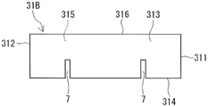
图3B是表示实施方式1的电抗器具备的第一磁芯块的进而另一例的概略俯视图。3B is a schematic plan view showing still another example of the first magnetic core block included in the reactor of Embodiment 1. FIG.
图3C是表示实施方式1的电抗器具备的第一磁芯块的进而另一例的概略俯视图。3C is a schematic plan view showing still another example of the first magnetic core block included in the reactor of Embodiment 1. FIG.
图3D是表示实施方式1的电抗器具备的第一磁芯块的进而另一例的概略俯视图。3D is a schematic plan view showing still another example of the first magnetic core block included in the reactor of Embodiment 1. FIG.
图4是表示实施方式2的电抗器的概略俯视图。4 is a schematic plan view showing a reactor according to
具体实施方式Detailed ways
[本公开要解决的课题][Problems to be Solved by the Present Disclosure]
希望一种难以磁饱和且制造性也优异的电抗器。A reactor that is difficult to magnetic saturation and is also excellent in manufacturability is desired.
如上所述如果在磁芯块间具备树脂间隙部,则即使在使用电流值大的情况下电抗器也难以磁饱和。然而,为了形成树脂间隙部,需要将相邻的磁芯块的间隔支承为规定的大小的构件,在专利文献1中为内侧夹设部51。因此,部件个数多。由于部件个数多而组装时间变长,电抗器的制造性下降。As described above, if the resin gap portion is provided between the core blocks, the reactor is less likely to be magnetically saturated even when the current value used is large. However, in order to form the resin gap portion, a member for supporting the interval between adjacent magnetic core blocks to a predetermined size is required, which is the inner interposition portion 51 in Patent Document 1. As shown in FIG. Therefore, the number of parts is large. Since the number of parts is large, the assembly time becomes long, and the manufacturability of the reactor decreases.
在取代上述的树脂间隙部而具备氧化铝板这样的间隙板的情况下,部件个数也多。而且,如专利文献1的说明书[0019]记载那样,在利用粘接剂将磁芯块与间隙板接合的情况下,也需要粘接剂的固化时间。由于上述的情况而电抗器的制造性下降。In the case where a gap plate such as an alumina plate is provided instead of the above-described resin gap portion, the number of parts is also large. Furthermore, as described in the specification [0019] of Patent Document 1, when the magnetic core block and the gap plate are joined by an adhesive, the curing time of the adhesive is also required. The manufacturability of the reactor decreases due to the above-mentioned situation.
因此,本公开的目的之一在于提供一种难以磁饱和且制造性也优异的电抗器。Therefore, one of the objects of the present disclosure is to provide a reactor which is difficult to magnetically saturate and which is excellent in manufacturability.
[本公开的效果][Effects of the present disclosure]
本公开的电抗器难以磁饱和且制造性也优异。The reactor of the present disclosure is difficult to magnetically saturate and is also excellent in manufacturability.
[本公开的实施方式的说明][Description of Embodiments of the Present Disclosure]
首先,列举本公开的实施形态进行说明。First, an embodiment of the present disclosure will be described.
(1)本公开的一形态的电抗器具备:(1) The reactor of one aspect of the present disclosure includes:
线圈,具有卷绕部;及a coil having a winding portion; and
磁芯,配置在所述卷绕部的内侧和所述卷绕部的外侧,a magnetic core arranged inside the winding portion and outside the winding portion,
所述磁芯通过将多个磁芯块组合而构成,The magnetic core is formed by combining a plurality of magnetic core blocks,
所述多个磁芯块中的至少一个磁芯块是复合材料的成形体构成的第一磁芯块,所述复合材料包含磁性粉末和树脂,At least one of the plurality of magnetic core blocks is a first magnetic core block composed of a molded body of a composite material, the composite material containing magnetic powder and resin,
所述第一磁芯块在配置于所述卷绕部的内侧的部位具备狭缝部,The first magnetic core block includes a slit portion at a portion arranged inside the winding portion,
所述狭缝部的深度方向沿着与所述第一磁芯块的轴向交叉的方向,The depth direction of the slit portion is along a direction intersecting with the axial direction of the first magnetic core block,
所述狭缝部以在所述第一磁芯块的外周面中的所述深度方向的一方开口且所述深度方向的另一方封闭的方式设置。The slit portion is provided so as to be open on one side of the outer peripheral surface of the first magnetic core block in the depth direction and to be closed on the other side in the depth direction.
本公开的电抗器如以下说明那样难以磁饱和且制造性也优异。The reactor of the present disclosure is difficult to magnetically saturate as described below, and is also excellent in manufacturability.
(磁特性)(magnetic properties)
在本公开的电抗器中,第一磁芯块以第一磁芯块的轴向沿着卷绕部的轴向即线圈的磁通方向的方式配置。其结果是,第一磁芯块的狭缝部以与上述磁通方向交叉的方式配置。这样的狭缝部可以利用作为磁间隙。因此,本公开的电抗器即使在使用电流值大的情况下也难以磁饱和。进而,本公开的电抗器即使在使用电流值大的情况下,也能够维持规定的电感。需要说明的是,此处的狭缝部的深度方向代表性地是沿着如下直线的方向,该直线是从设置于第一磁芯块的外周面的开口部朝向第一磁芯块的内部直至狭缝部的底部为止取得最长距离的直线。详情在后文叙述。而且,上述第一磁芯块的轴向代表性地相当于第一磁芯块的长度方向。In the reactor of the present disclosure, the first magnetic core block is arranged so that the axial direction of the first magnetic core block is along the axial direction of the winding portion, that is, the magnetic flux direction of the coil. As a result, the slit portion of the first core block is arranged so as to intersect the magnetic flux direction described above. Such a slit portion can be used as a magnetic gap. Therefore, the reactor of the present disclosure is difficult to magnetically saturate even when the use current value is large. Furthermore, the reactor of the present disclosure can maintain a predetermined inductance even when the used current value is large. It should be noted that the depth direction of the slit portion here is typically a direction along a straight line from the opening provided in the outer peripheral surface of the first core block toward the inside of the first core block A straight line with the longest distance is obtained up to the bottom of the slit portion. Details will be described later. In addition, the axial direction of the above-mentioned first magnetic core block typically corresponds to the longitudinal direction of the first magnetic core block.
第一磁芯块是复合材料的成形体。复合材料的成形体与电磁钢板的层叠体或压粉成形体或压粉磁心相比,代表性地包含较多的作为非磁性材料的树脂。复合材料的成形体例如包含10体积%以上的树脂。从复合材料中的树脂作为磁间隙发挥作用的情况出发,本公开的电抗器也难以磁饱和。The first core block is a formed body of composite material. The molded body of the composite material typically contains a larger amount of resin as a non-magnetic material than the laminated body of the electromagnetic steel sheet, the powder molded body, or the powder magnetic core. The molded body of the composite material contains, for example, 10% by volume or more of resin. Since the resin in the composite material functions as a magnetic gap, the reactor of the present disclosure is also difficult to magnetically saturate.
(制造性)(manufacturability)
本公开的电抗器在第一磁芯块自身具备作为磁间隙发挥作用的狭缝部。第一磁芯块与磁间隙为一体的成形物,因此可以省略上述的保持相邻的磁芯块的间隔的构件或间隙板等。除了能够削减部件个数的情况之外,也不需要将磁芯块与间隙板接合的粘接剂的固化时间,因此本公开的电抗器在制造性上优异。此外,具有狭缝部的第一磁芯块是复合材料的成形体,因此能够通过注塑成形等容易地形成。从这一点出发,本公开的电抗器在制造性上也优异。需要说明的是,狭缝部制成的磁间隙也可以为空气间隙。The reactor of the present disclosure includes a slit portion that functions as a magnetic gap in the first core block itself. Since the first magnetic core block and the magnetic gap are integrally formed, the above-described member for maintaining the gap between the adjacent magnetic core blocks, the gap plate, and the like can be omitted. In addition to the case where the number of parts can be reduced, the curing time of the adhesive for joining the magnetic core block and the gap plate is not required, so the reactor of the present disclosure is excellent in manufacturability. In addition, the first magnetic core block having the slit portion is a molded body of a composite material, and thus can be easily formed by injection molding or the like. From this point, the reactor of the present disclosure is also excellent in manufacturability. It should be noted that the magnetic gap formed by the slit portion may be an air gap.
此外,本公开的电抗器由于第一磁芯块为复合材料的成形体,因此为低损失且小型。详细而言,复合材料的成形体如上所述与电磁钢板的层叠体或压粉成形体相比难以磁饱和。因此,能够减薄狭缝部的厚度。由于狭缝部的厚度薄至一定程度而减少来自狭缝部的漏磁通。即便使卷绕部与第一磁芯块接近,也能减少以上述漏磁通为起因的损失例如铜损。从这一点出发,本公开的电抗器为低损失。复合材料包含树脂且在电绝缘性上优异,因此能减少涡电流损失。从减少铁损这样的交流损失的情况出发,本公开的电抗器也为低损失。此外,在能够减小卷绕部与第一磁芯块之间的间隔的点上,本公开的电抗器为小型。从如上所述电绝缘性优异的情况出发,卷绕部与第一磁芯块之间的间隔也容易减小。需要说明的是,此处的狭缝部的厚度是沿第一磁芯块的轴向的最大长度。In addition, the reactor of the present disclosure has low loss and small size because the first magnetic core block is a molded body of a composite material. In detail, as described above, the formed body of the composite material is less likely to be magnetically saturated than the laminated body or the dust formed body of the electrical steel sheet. Therefore, the thickness of the slit portion can be reduced. Since the thickness of the slit portion is thinned to some extent, the leakage magnetic flux from the slit portion is reduced. Even if the winding portion is brought close to the first core block, the loss caused by the above-mentioned leakage magnetic flux, such as copper loss, can be reduced. From this point of view, the reactor of the present disclosure is low loss. The composite material contains resin and is excellent in electrical insulating properties, so eddy current loss can be reduced. The reactor of the present disclosure is also low in loss in terms of reducing AC loss such as iron loss. In addition, the reactor of the present disclosure is small in size in that the interval between the winding portion and the first magnetic core block can be reduced. Since the electrical insulating property is excellent as described above, the gap between the winding portion and the first magnetic core block is also easily reduced. It should be noted that the thickness of the slit portion here is the maximum length along the axial direction of the first magnetic core block.
此外,本公开的电抗器虽然第一磁芯块具有狭缝部,但是在强度上也优异。其理由是因为,第一磁芯块容易将狭缝部封闭的一侧的区域的体积确保得大至一定程度,容易提高机械强度。Furthermore, the reactor of the present disclosure is excellent in strength even though the first core block has the slit portion. The reason for this is that the volume of the region on the side where the slit portion of the first core block is likely to be closed is increased to a certain extent, and it is easy to improve the mechanical strength.
(2)作为本公开的电抗器的一例,可列举如下的方式:(2) As an example of the reactor of the present disclosure, the following modes can be listed:
所述狭缝部的深度的沿着与所述轴向正交的方向的大小为所述第一磁芯块的沿着与所述轴向正交的方向的长度的1/3以上且1/2以下。The size of the depth of the slit portion along the direction orthogonal to the axial direction is equal to or greater than 1/3 of the length of the first core block along the direction orthogonal to the axial direction and 1 /2 or less.
上述方式中的狭缝部作为磁间隙良好地发挥作用。因此,上述方式难以磁饱和。而且,上述方式中的狭缝部不会过深。因此,第一磁芯块在成形性上优异。而且,容易将第一磁芯块中的狭缝部封闭的一侧的区域的体积确保得较大。因此,上述方式在制造性上优异,而且在强度上也优异。The slit portion in the above-described form functions well as a magnetic gap. Therefore, the above-described method is difficult to magnetic saturation. Moreover, the slit part in the above-mentioned form is not too deep. Therefore, the first magnetic core block is excellent in formability. Furthermore, it is easy to secure a large volume of the region on the side where the slit portion in the first core block is closed. Therefore, the above-mentioned form is excellent in manufacturability and also in strength.
(3)作为本公开的电抗器的一例,可列举如下的方式:(3) As an example of the reactor of the present disclosure, the following forms can be listed:
所述第一磁芯块具备多个所述狭缝部。The first magnetic core block includes a plurality of the slit portions.
在上述方式中,各狭缝部在第一磁芯块的轴向的不同的位置向相同的朝向或不同的朝向开口。即,各狭缝部在第一磁芯块的外周面以各狭缝部的深度方向的双方都不开口的方式设置。这样的方式与以向上述的深度方向的双方开口的方式设置狭缝部的情况相比,难以磁饱和。In the above-described aspect, each slit portion is opened in the same direction or in a different direction at different positions in the axial direction of the first magnetic core block. That is, each slit part is provided in the outer peripheral surface of a 1st magnetic core block so that both sides of the depth direction of each slit part may not open. Compared with the case where the slits are provided so as to be open to both sides of the above-mentioned depth direction, magnetic saturation is less likely to be achieved in such an aspect.
另外,上述方式具备多个狭缝部,因此容易减薄各狭缝部的厚度。这样的方式即使如上所述使卷绕部与第一磁芯块接近,也为低损失。而且,上述方式通过上述的接近配置而为小型。In addition, since the above-described form includes a plurality of slit portions, it is easy to reduce the thickness of each slit portion. In such a method, even if the winding portion and the first core block are brought close to each other as described above, the loss is low. Moreover, the above-mentioned form is compact by the above-mentioned close arrangement.
此外,上述方式虽然具备多个狭缝部,但是各狭缝部的形成位置在第一磁芯块的轴向上错开。因此,容易将第一磁芯块中的各狭缝部封闭的一侧的区域的体积确保得大至一定程度。这样的方式如上所述在强度上也优异。In addition, although the said form is provided with a several slit part, the formation position of each slit part is shifted in the axial direction of a 1st magnetic core block. Therefore, the volume of the region on the side where each slit portion in the first magnetic core block is closed can be easily secured to a certain extent. Such an aspect is also excellent in strength as described above.
(4)作为本公开的电抗器的一例,可列举如下的方式:(4) As an example of the reactor of the present disclosure, the following modes can be listed:
假想将利用与所述轴向正交的平面剖切所述第一磁芯块而得到的截面的外形包含在内的最小的长方形,Assuming the smallest rectangle including the outer shape of the cross-section obtained by cutting the first magnetic core block with a plane orthogonal to the axial direction,
所述狭缝部的深度方向是沿着假想的所述长方形的短边的方向。The depth direction of the slit portion is a direction along the short side of the imaginary rectangle.
上述方式与狭缝部的深度方向为沿着上述假想的长方形的长边的方向的情况相比,容易成形出狭缝部。因此,上述方式在制造性上更优异。Compared with the case where the depth direction of a slit part is the direction along the long side of the said virtual rectangle, the said form is easy to form a slit part. Therefore, the above-mentioned form is more excellent in manufacturability.
(5)作为本公开的电抗器的一例,可列举如下的方式:(5) As an example of the reactor of the present disclosure, the following modes can be listed:
所述线圈具备相邻地排列的两个所述卷绕部,The coil includes two of the winding portions arranged adjacent to each other,
所述磁芯具备:The magnetic core has:
所述第一磁芯块,包含配置在一方的所述卷绕部的内侧的所述狭缝部;及the first magnetic core block including the slit portion disposed inside one of the winding portions; and
第二磁芯块,包含配置在另一方的所述卷绕部的内侧的部位,由所述复合材料的成形体构成,且未设置所述狭缝部。The second magnetic core block includes a portion arranged inside the other winding portion, and is formed of a molded body of the composite material, and the slit portion is not provided.
上述方式将具有狭缝部的第一磁芯块及配置第一磁芯块的一方的卷绕部配置在接近冷却机构的一侧,由此,如以下说明那样,散热性也优异。在此,例如,第一磁芯块与第二磁芯块除了狭缝部的有无之外,复合材料的组成、磁芯块的形状、大小等规格实质上相等。在该情况下,配置具有狭缝部的第一磁芯块的一方的卷绕部与配置不具有狭缝部的第二磁芯块的另一方的卷绕部相比容易发热。其理由是因为,一方的卷绕部由于来自狭缝部的漏磁通而容易产生铜损。相对容易成为高温的第一磁芯块及一方的卷绕部配置在接近冷却机构的一侧,相对难以成为高温的第二磁芯块及另一方的卷绕部配置在远离冷却机构的一侧,由此,第一磁芯块及一方的卷绕部能够向冷却机构高效地散热。需要说明的是,冷却机构也可以内置于电抗器的设置对象。In the above-described embodiment, the first core block having the slit portion and the winding portion on which the first core block is arranged are arranged on the side close to the cooling mechanism, thereby providing excellent heat dissipation as described below. Here, for example, the first magnetic core block and the second magnetic core block have substantially the same specifications, such as the composition of the composite material, the shape and size of the magnetic core block, except for the presence or absence of the slit. In this case, the one winding portion on which the first magnetic core block having the slit portion is arranged is more likely to generate heat than the other winding portion on which the second magnetic core block having no slit portion is arranged. The reason for this is that copper loss is likely to occur in one winding portion due to leakage magnetic flux from the slit portion. The first core block and the one winding part, which are relatively easy to become high temperature, are arranged on the side close to the cooling mechanism, and the second core block and the other winding part which are relatively difficult to become high temperature are arranged on the side away from the cooling mechanism. Accordingly, the first core block and the one winding portion can efficiently dissipate heat to the cooling mechanism. In addition, the cooling mechanism may be built in the installation object of a reactor.
另外,第一磁芯块及第二磁芯块这双方为复合材料的成形体,能够通过注塑成形等容易地形成。因此,上述方式在制造性上更优异。In addition, both the first magnetic core block and the second magnetic core block are formed bodies of a composite material, and can be easily formed by injection molding or the like. Therefore, the above-mentioned form is more excellent in manufacturability.
此外,第一磁芯块及第二磁芯块这双方为复合材料的成形体,因此即使如上所述使各卷绕部与各磁芯块接近,该方式也为低损失。而且,通过上述的接近配置,该方式能够为小型的电抗器。In addition, since both the first core block and the second core block are formed bodies of a composite material, even if each winding portion and each core block are brought close to each other as described above, this method has low loss. Furthermore, by the above-described proximity arrangement, this method can be used as a small-sized reactor.
(6)作为本公开的电抗器的一例,可列举如下的方式:(6) As an example of the reactor of the present disclosure, the following forms can be mentioned:
所述狭缝部的沿所述第一磁芯块的周向的开口缘的长度为所述第一磁芯块的周长的1/3以上且1/2以下。The length of the opening edge of the slit portion along the circumferential direction of the first magnetic core block is not less than 1/3 and not more than 1/2 of the circumferential length of the first magnetic core block.
上述方式中的狭缝部可以说具有大的开口部。这样的第一磁芯块在制造过程中容易拔出成形狭缝部的型材,因此成形性优异。因此,上述方式在制造性上更优异。而且,上述方式中的狭缝部不会过大,容易将第一磁芯块中的狭缝部封闭的一侧的区域的体积确保得较大。因此,上述方式在强度上也优异。It can be said that the slit part in the said form has a large opening part. Such a first magnetic core block is easy to pull out of the profile forming the slit portion in the manufacturing process, and thus has excellent formability. Therefore, the above-mentioned form is more excellent in manufacturability. Furthermore, in the above-described aspect, the slit portion is not too large, and it is easy to secure a large volume of the region on the side closed by the slit portion in the first magnetic core block. Therefore, the above-mentioned form is also excellent in strength.
(7)作为本公开的电抗器的一例,可列举如下的方式:(7) As an example of the reactor of the present disclosure, the following forms can be mentioned:
所述复合材料的成形体的相对磁导率为5以上且50以下,The relative magnetic permeability of the formed body of the composite material is 5 or more and 50 or less,
配置在所述卷绕部的外侧的第三磁芯块的相对磁导率为所述复合材料的成形体的相对磁导率的2倍以上。The relative magnetic permeability of the third magnetic core block disposed outside the winding portion is twice or more the relative magnetic permeability of the composite material molded body.
上述方式与复合材料的成形体的相对磁导率与第三磁芯块的相对磁导率为5~50且相同的情况相比,具有大的电感,且容易成为小型。这里的复合材料的成形体构成第一磁芯块,在上述(5)的方式中构成第一磁芯块及第二磁芯块。Compared with the case where the relative magnetic permeability of the composite material molded body is 5 to 50 and the relative magnetic permeability of the third magnetic core block is the same, the above-mentioned form has a large inductance and is easy to be reduced in size. The molded body of the composite material here constitutes the first magnetic core block, and in the aspect (5) above, the first magnetic core block and the second magnetic core block are constituted.
另外,复合材料的成形体的相对磁导率比较低。这样的包含低磁导率的复合材料的成形体的方式难以磁饱和。由于难以磁饱和,因此能够减薄狭缝部的厚度。如果狭缝部的厚度较薄,则能减少来自狭缝部的漏磁通。而且,即使如上所述使卷绕部与第一磁芯块或第二磁芯块接近,也能减少损失。这样的方式如上所述为低损失且小型。In addition, the relative permeability of the formed body of the composite material is relatively low. Such a form of a formed body containing a composite material with low magnetic permeability is difficult to magnetically saturate. Since magnetic saturation is difficult, the thickness of the slit portion can be reduced. When the thickness of the slit portion is thin, the leakage magnetic flux from the slit portion can be reduced. Furthermore, even if the winding portion is brought close to the first core block or the second core block as described above, the loss can be reduced. Such a system is low-loss and compact as described above.
此外,上述方式能减少第三磁芯块与第一磁芯块或第二磁芯块之间的漏磁通。这样的方式由于减少以上述的漏磁通为起因的损失,因此为低损失。In addition, the above method can reduce the leakage magnetic flux between the third magnetic core block and the first magnetic core block or the second magnetic core block. Since such a system reduces the loss caused by the above-mentioned leakage magnetic flux, the loss is low.
(8)作为上述(7)的电抗器的一例,可列举如下的方式:(8) As an example of the reactor of the above (7), the following forms can be mentioned:
所述第三磁芯块的相对磁导率为50以上且500以下。The relative permeability of the third magnetic core block is 50 or more and 500 or less.
上述方式容易将第三磁芯块与第一磁芯块或第二磁芯块之间的相对磁导率之差确保得较大。因此,上述方式更容易减少第三磁芯块与第一磁芯块或第二磁芯块之间的漏磁通,为更低损失。The above method can easily ensure a large difference in relative permeability between the third magnetic core block and the first magnetic core block or the second magnetic core block. Therefore, in the above manner, it is easier to reduce the leakage magnetic flux between the third magnetic core block and the first magnetic core block or the second magnetic core block, resulting in lower loss.
(9)作为上述的电抗器的一例,可列举如下的方式:(9) As an example of the above-mentioned reactor, the following forms can be mentioned:
所述电抗器具备将所述磁芯的至少一部分覆盖的树脂模制部。The reactor includes a resin mold portion covering at least a part of the magnetic core.
上述方式虽然具备多个磁芯块,但是能够利用树脂模制部保持多个磁芯块。通过树脂模制部,能提高磁芯的作为一体物的强度,因此上述方式在强度上也优异。而且,上述方式通过树脂模制部,能实现线圈与磁芯之间的电绝缘性的提高、保护免于受到外部环境的影响、机械保护等。Although the above-described method includes a plurality of magnetic core blocks, the plurality of magnetic core blocks can be held by the resin mold portion. The resin-molded portion can improve the strength of the magnetic core as a single body, and thus the above-described aspect is also excellent in strength. Furthermore, in the above-described manner, the resin mold portion can achieve improvement in electrical insulation between the coil and the magnetic core, protection from external environment, mechanical protection, and the like.
[本公开的实施方式的详情][Details of Embodiments of the Present Disclosure]
以下,参照附图,具体说明本公开的实施方式。图中的相同标号表示相同名称物。Hereinafter, embodiments of the present disclosure will be described in detail with reference to the accompanying drawings. The same reference numerals in the figures denote the same names.
[实施方式1][Embodiment 1]
参照图1~图3D,说明实施方式1的电抗器1。The reactor 1 of Embodiment 1 will be described with reference to FIGS. 1 to 3D .
图1是实施方式1的电抗器1的从与线圈2的卷绕部2a、2b的轴向和两个卷绕部2a、2b排列的方向这双方正交的方向观察到的俯视图。在此,上述轴向相当于图1的纸面左右方向。上述卷绕部2a、2b排列的方向相当于图1的纸面上下方向。上述正交的方向相当于图1的纸面垂直方向。1 is a plan view of the reactor 1 according to Embodiment 1 as viewed from a direction orthogonal to both the axial direction of the winding
<概要><Summary>
如图1所示,实施方式1的电抗器1具备:具有卷绕部的线圈2;在卷绕部的内侧和卷绕部的外侧配置的磁芯3。本例的线圈2具有相邻地排列的两个卷绕部2a、2b。各卷绕部2a、2b以各轴平行的方式配置。磁芯3通过将多个磁芯块组合而构成。本例的磁芯3具备:包含配置在一方的卷绕部2a的内侧的部位的第一磁芯块31a;包含配置在另一方的卷绕部2b的内侧的部位的第二磁芯块31b;配置在卷绕部2a、2b的外侧的第三磁芯块32。磁芯3通过将上述磁芯块31a、31b、32组装成环状而构成。磁芯块31a、31b以各轴向沿着卷绕部2a、2b的轴向的方式配置。两个磁芯块32以夹持两磁芯块31a、31b的方式配置。这样的电抗器1代表性地安装于转换器箱等这样的未图示的设置对象使用。As shown in FIG. 1 , the reactor 1 according to Embodiment 1 includes a
特别是在实施方式1的电抗器1中,作为构成磁芯3的磁芯块,包括设有狭缝部7的第一磁芯块31a。而且,第一磁芯块31a设为包含树脂的成形体。详细而言,多个磁芯块中的至少一个磁芯块是由包含磁性粉末和树脂的复合材料的成形体构成的第一磁芯块31a。第一磁芯块31a在配置于卷绕部2a的内侧的部位具备狭缝部7。狭缝部7的深度方向沿着与第一磁芯块31a的轴向交叉的方向。狭缝部7以在第一磁芯块31a的外周面中的深度方向的一方开口且所述深度方向的另一方封闭的方式设置。In particular, in the reactor 1 of the first embodiment, the first
狭缝部7的深度方向代表性地是沿着如下直线的方向,该直线是从设置于第一磁芯块31a的狭缝部7的开口部朝向第一磁芯块31a的内部直至狭缝部7的底部在图1中为内底面70的取得最长距离的直线。在如本例那样狭缝部7由一个内底面70和平行地配置的两个内壁面71构成的情况下,狭缝部7的深度方向是沿着内壁面71的沿面方向的方向。在本例中,狭缝部7的深度方向是与第一磁芯块31a的轴向正交的方向。上述轴向在图1中相当于纸面左右方向。上述正交的方向在图1中相当于纸面上下方向。The depth direction of the
另外,本例的第一磁芯块31a为长方体状(图2A)。因此,第一磁芯块31a的外周面包括两个端面311、312和四个周面313~316。本例的狭缝部7以在第一磁芯块31a的外周面中的位于深度方向的一方的周面314开口且位于深度方向的另一方的周面316封闭的方式设置。即,狭缝部7相对于相对的周面314、316以在一方的周面314具有开口部且在另一方的周面316不具有开口部的方式设置。In addition, the 1st
需要说明的是,虽然省略图示,但是在构成狭缝部7的内周面具有多个内底面的情况下,狭缝部7的深度方向设为以下那样。取得将第一磁芯块31a利用与其轴向正交的平面剖切而得到的截面。假想将该截面的外形包含在内的最小的长方形。将狭缝部7向该假想的长方形投影。并且,在狭缝部7的投影像中,将沿着上述长方形的短边方向或上述长方形的长边方向的方向设为狭缝部7的深度方向。需要说明的是,在上述内周面具有多个内底面的情况下,可列举例如在长方体状的第一磁芯块31a的角部设置狭缝部7,狭缝部7由配置成L字状的两个内底面和两个壁面构成的情况等。In addition, although illustration is abbreviate|omitted, when the inner peripheral surface which comprises the
第一磁芯块31a以第一磁芯块31a的轴向沿着卷绕部2a的轴向即线圈2的磁通方向的方式配置。其结果是,狭缝部7以与线圈2的磁通方向交叉的方式配置。本例的狭缝部7以与线圈2的磁通方向正交的方式配置。这样的狭缝部7作为磁间隙发挥作用,有助于使电抗器1难以磁饱和。而且,狭缝部7与第一磁芯块31a形成为一体,有助于电抗器1的部件个数的削减。需要说明的是,这里的第一磁芯块31a的轴向相当于磁芯块31a的长度方向。The
以下,对于每个构成要素进行详细说明。Hereinafter, each constituent element will be described in detail.
<线圈><coil>
本例的线圈2具备将未图示的绕组卷绕成螺旋状而成的筒状的卷绕部2a、2b。作为具备相邻地排列的两个卷绕部2a、2b的线圈2,可列举以下的方式。The
(i)线圈2具备通过独立的两根绕组分别形成的卷绕部2a、2b和未图示的连接部。连接部通过将从卷绕部2a、2b引出的绕组的两端部中的一方的端部彼此连接而构成。(i) The
(ii)线圈2具备由一根连续的绕组形成的卷绕部2a、2b和未图示的连结部。连结部由架设于卷绕部2a、2b之间的绕组的一部分构成,将卷绕部2a、2b连结。(ii) The
在(ii)中从各卷绕部2a、2b引出的绕组的端部、在(i)中未使用于连接部的另一方的端部被利用作为连接电源等外部装置的部位。(i)的连接部可列举将绕组的端部彼此直接连接的方式和间接连接的方式。直接连接可以利用焊接或压接等。间接连接可以利用安装于绕组的端部的适当的配件等。The ends of the coils drawn out from the respective winding
绕组可列举具备导体线和将导体线的外周覆盖的绝缘包覆的包覆线。导体线的构成材料可列举铜等。绝缘包覆的构成材料可列举聚酰胺酰亚胺等树脂。作为包覆线的具体例,可列举截面形状为长方形的包覆扁线,截面形状为圆形的包覆圆线。作为由扁线构成的卷绕部2a、2b的具体例,可列举扁立卷绕线圈。Examples of the winding include a conductor wire and a covered wire having an insulating coating covering the outer periphery of the conductor wire. The constituent material of the conductor wire includes copper and the like. Examples of the constituent material of the insulating coating include resins such as polyamideimide. As a specific example of a covered wire, the covered rectangular wire whose cross-sectional shape is a rectangle, and the covered round wire whose cross-sectional shape is a circle are mentioned. As a specific example of the winding
本例的卷绕部2a、2b是方形筒状的扁立卷绕线圈。而且,在本例中,卷绕部2a、2b的形状、卷绕方向、匝数等规格相等。绕组、卷绕部2a、2b的形状、大小等可以适当变更。例如,卷绕部2a、2b的形状也可以为圆筒状等。或者,例如,各卷绕部2a、2b的规格也可以不同。The winding
<磁芯><Core>
《概要》"summary"
本例的磁芯3通过如上所述将磁芯块31a、31b和两个磁芯块32这总计四个磁芯块组合成环状而构成闭磁路。本例的第一磁芯块31a包含配置在一方的卷绕部2a的内侧的狭缝部7。本例的第二磁芯块31b包含配置于另一方的卷绕部2b的内侧的部位,且未设置狭缝部7。在本例中,两个第三磁芯块32分别配置于卷绕部2a、2b的外侧,且未设置狭缝部7。主要配置于卷绕部2a、2b的内侧的磁芯块31a、31b与配置于卷绕部2a、2b的外侧的磁芯块32是独立的磁芯块。在该情况下,能提高磁芯块的构成材料的自由度。在本例中,线圈2内的磁芯块31a、31b的构成材料与线圈2外的磁芯块32的构成材料不同。磁芯块31a、31b的构成材料同等。而且,配置于一个卷绕部2a或2b的内侧的磁芯块的个数为一个。因此,磁芯3、甚至电抗器1的部件个数少。磁芯块的构成材料、个数可以适当变更。关于变更的结构,例如可参照后述的变形例E、G。The
《磁芯块的形状、大小》"The shape and size of the core block"
本例的磁芯块31a、31b、32都为长方体状。本例的磁芯块31a、31b除了狭缝部7的有无之外,大致为相同形状,大致为相同大小。各磁芯块31a、31b为细长的长方体状,如上所述以长度方向沿卷绕部2a、2b的轴向的方式配置。各磁芯块31a、31b的外周形状与卷绕部2a、2b的内周形状大致相似。各磁芯块31a、31b的端面311、312的形状为长方形状,短边长度<长边长度(图2D)。在本例中,两个磁芯块32为相同形状、相同大小。在各磁芯块32中,连接磁芯块31a、31b的面具有比两个端面311、312的总计面积大的面积。磁芯块31a、31b、32的大小以电抗器1满足规定的磁特性的方式,根据构成材料、狭缝部7的大小等来调整。The
需要说明的是,磁芯块31a、31b、32的形状、大小等可以适当变更。例如,磁芯块31a、31b的形状也可以为圆柱状、多角柱状等。或者,例如,第三磁芯块32的形状也可以为专利文献1所示的具有圆顶状的面或梯形形状的面的柱状体。此外,例如,磁芯块的角部的至少一部分也可以被进行C倒角或R倒角。被倒角后的角部难以缺欠,磁芯块在机械强度上优异。需要说明的是,被R倒角后的角部可以参照第三磁芯块32。In addition, the shape, size, etc. of the
《狭缝部》"The Slit"
以下,主要参照图2A~图2D、图3A~图3D,对狭缝部7进行说明。Hereinafter, the
第一磁芯块31a具备至少一个狭缝部7。狭缝部7以在第一磁芯块31a的外周面中的狭缝部7的深度方向的一方开口且所述深度方向的另一方封闭的方式设置于第一磁芯块31a。这样的狭缝部7在第一磁芯块31a的外周面的一部分开口。而且,狭缝部7是未贯穿第一磁芯块31a的凹部。狭缝部7代表性地具有薄板状的内部空间(图2A)。如图3B~图3D所示,在第一磁芯块31B~31D具备多个狭缝部7的情况下,各狭缝部7以在磁芯块31B~31D的外周面各狭缝部7的深度方向的双方不开口的方式设置。The
《基本结构》"basic structure"
本例的狭缝部7由相对的两个内壁面71和将两内壁面71连接的内底面70形成(图1等)。各内壁面71与第一磁芯块31a的轴向正交地设置。内底面70与第一磁芯块31a的轴向平行地设置。该狭缝部7在第一磁芯块31a的外周面中的位于狭缝部7的深度方向的一方的周面314开口。位于狭缝部7的深度方向的另一方的周面316封闭。即,本例的周面316不具有凹部,周面316的整体由一样的平面构成。此外,本例的狭缝部7也在与周面314连接的周面313、315的一部分开口。详细而言,本例的狭缝部7以贯穿周面313、315并与三个周面313~315连接而开口的方式设置。其余的一个周面316封闭。狭缝部7沿第一磁芯块31a的周向连续,在多个周面313~315上开口,由此开口缘的长度比较长。也参照后述的开口缘的长度的项。这样的具有狭缝部7的第一磁芯块31a在成形性上优异。其理由是因为,在第一磁芯块31a的成形过程中,容易拔出成形狭缝部7的型材。The
在本例中,如图2D所示,内壁面71的形状是通过沿着第一磁芯块31a的三个周面313~315的门型的开口缘和将开口缘的两端部连结的直线描绘的长方形状。内壁面71的形状只要是通过开口缘和将开口缘的两端部连结的直线描绘的形状即可,狭缝部7可以说是简单的形状。因此,具有狭缝部7的第一磁芯块31a在成形性上优异。在本例中,内底面70的形状也为长方形状,狭缝部7的内部空间为长方体状。从这一点出发,狭缝部7也为简单的形状,第一磁芯块31a在成形性上优异。In this example, as shown in FIG. 2D , the shape of the
内壁面71、内底面70的形状可以适当变更。例如,也可以将内壁面71设为通过开口缘和连结开口缘的两端的曲线描绘的形状,内底面70为弯曲面等曲线形状。或者,例如,也可以省略内底面70。在该情况下,可列举两个内壁面71中的底部侧的缘相连,周面313、315的开口缘的形状为三角形形状的情况。在该情况下,狭缝部7的内部空间为三角柱状。The shapes of the
在本例中,内壁面71与第一磁芯块31a的外周面,在此为周面314实质上正交。因此,内壁面71的相对于上述外周面,在此为周面314的交叉角度为90°。内壁面71的相对于第一磁芯块31a的外周面的交叉状态,例如上述交叉角度可以适当变更。上述交叉角度只要从超过0°且小于180°中适当选择即可。例如,内壁面71也可以相对于第一磁芯块31a的外周面非正交地交叉。非正交地交叉的结构可以参照后述的变形例D,即图3A所示的第一磁芯块31A具备的狭缝部7A。In this example, the
《深度方向》"Depth Direction"
狭缝部7的深度方向只要是与第一磁芯块31a的轴向交叉的方向,即与线圈2的磁通方向交叉的方向即可。特别是狭缝部7的深度方向越接近与线圈2的磁通方向正交的方向,则越作为磁间隙而良好地发挥作用。本例的狭缝部7的深度方向是与第一磁芯块31a的轴向正交的方向,即与上述磁通方向正交的方向(图1、图2B)。The depth direction of the
假想将对第一磁芯块31a利用与其轴向正交的平面剖切而得到的截面的外形包含在内的最小的长方形,狭缝部7的深度方向可列举沿着该假想的长方形的短边的方向的方式。本例的第一磁芯块31a为长方体状。因此,利用与第一磁芯块31a的轴向正交的平面剖切而得到的截面形状为长方形。在该情况下,上述假想的长方形可以直接利用第一磁芯块31a的外形。第一磁芯块31a如果为例如椭圆柱、端面形状为跑道状的柱状体等,则取得上述的截面。并且,对于截面的外形例如椭圆、跑道等,只要假想地取得将该截面的外形包含在内的最小的长方形即可。Assuming the smallest rectangle including the outer shape of the cross-section obtained by cutting the
在狭缝部7的深度方向沿着上述的假想的长方形的短边方向的情况下,与沿着上述假想的长方形的长边方向的情况相比,第一磁芯块31a在成形性上优异,容易制造第一磁芯块31a。进而,电抗器1在制造性上优异。其理由是因为,即使是使狭缝部7的深度d7(图2B、图2D)比较大,也容易拔出上述的型材。如果第一磁芯块31a为本例所示的长方体、其他椭圆体这样的简单的形状,则第一磁芯块31a在成形性上更优异,更容易制造。When the depth direction of the
在此的狭缝部7的深度d7是沿深度方向的最大长度。在本例中,深度d7是沿着与第一磁芯块31a的轴向正交的方向的最大长度。需要说明的是,后述的狭缝部7的厚度t7(图2B、图2C)是沿第一磁芯块31a的轴向的最大长度。而且,后述的狭缝部7的高度h7(图2C、图2D)是沿着与第一磁芯块31a的轴向及深度方向这双方正交的方向的最大长度。The depth d 7 of the
《大小》"size"
狭缝部7的大小,例如厚度t7、深度d7、高度h7、开口缘的长度等可以在电抗器1满足规定的磁特性的范围内适当选择。The size of the
厚度t7、深度d7、高度h7越大,则狭缝部7的内部体积越容易确保得较大。狭缝部7的内部体积大的电抗器1难以磁饱和。而且,厚度t7越大,则越容易拔出上述的型材,第一磁芯块31a在成形性上优异。The larger the thickness t 7 , the depth d 7 , and the height h 7 , the easier it is to ensure a larger internal volume of the
另一方面,厚度t7、高度h7越小,则越容易减少来自狭缝部7的漏磁通。如本例那样狭缝部7贯穿的情况下,深度d7也越小,则上述漏磁通越容易减少。从这一点出发,即便使卷绕部2a与第一磁芯块31a接近,也能减少以上述漏磁通为起因的损失,例如铜损。而且,通过上述的接近配置,电抗器1容易变得小型。因此,电抗器1为低损失且小型。此外,第一磁芯块31a中的狭缝部7封闭的一侧的区域的体积容易确保得较大,因此容易提高第一磁芯块31a的机械强度。其结果是,电抗器1为高强度。此外,深度d7、高度h7越小,则越容易拔出上述的型材,第一磁芯块31a在成形性上优异。On the other hand, the smaller the thickness t 7 and the height h 7 , the easier it is to reduce the leakage magnetic flux from the
虽然也受磁芯3的大小等的影响,但是如果厚度t7为例如1mm以上,则电抗器1难以磁饱和,而且在第一磁芯块31a的成形性上也优异。在希望磁饱和的减少、制造性的提高时等,厚度t7也可以为1.5mm以上,2mm以上。如果厚度t7为例如3mm以下,则来自狭缝部7的漏磁通容易减少。深度d7的详情可以参照后述的长度L7。高度h7如图2C例示那样与第一磁芯块31a的高度相等时,电抗器1难以磁饱和,而且在第一磁芯块31a的成形性上也优异。上述第一磁芯块31a的高度在此为相对配置的周面313、315之间的距离。Although also affected by the size of the
作为狭缝部7的大小的一例,可列举以下的例子。狭缝部7的深度d7的沿着与第一磁芯块31a的轴向正交的方向的长度L7(图2B、图2D)是第一磁芯块31a的沿着与轴向正交的方向的长度L3(图2B、图2D)的1/3以上且1/2以下。如果如本例那样狭缝部7的深度方向为与第一磁芯块31a的轴向正交的方向,则狭缝部7的长度L7相当于深度d7。如果狭缝部7的深度方向是与上述轴向非正交地交叉的方向,则长度L7相当于将狭缝部7的深度d7向与上述轴向在此为磁通方向正交的平面投影的长度。在本例中,第一磁芯块31a的长度L3相当于相对配置的周面314、316间的距离。此外,在本例中,第一磁芯块31a的长度L3相当于沿着长方形状的端面311、312的短边方向的长度。本例的狭缝部7的长度L7为第一磁芯块31a的长度L3的1/3以上且1/2以下。As an example of the magnitude|size of the
如果狭缝部7的长度L7为第一磁芯块31a的长度L3的1/3以上,即长度L3的33%以上,则狭缝部7作为磁间隙而良好地发挥作用。因此,电抗器1难以磁饱和。狭缝部7的长度L7越长,则能够将磁间隙确保得越大,电抗器1难以磁饱和。在希望磁饱和的减少时等,狭缝部7的长度L7也可以为磁芯块31a的长度L3的35%以上,进而为40%以上。When the length L7 of the slit portion 7 is 1/3 or more of the length L3 of the
如果狭缝部7的长度L7为第一磁芯块31a的长度L3的1/2以下,即长度L3的50%以下,则狭缝部7不会过深。因此,容易拔出上述的型材,第一磁芯块31a在成形性上优异。进而,电抗器1在制造性上优异。而且,容易减少来自狭缝部7的漏磁通。由此,电抗器1如上所述为低损失且小型。而且,狭缝部7不会过深,由此容易将第一磁芯块31a中的狭缝部7封闭的一侧的区域的体积确保得较大。由此,电抗器1如上所述为高强度。狭缝部7的长度L7越短,则越容易得到上述的效果。在希望制造性的提高、损失的减少、小型化、强度的提高时等,狭缝部7的长度L7也可以为磁芯块31a的长度L3的48%以下,进而45%以下。If the length L 7 of the
狭缝部7中的沿第一磁芯块31a的周向的开口缘的长度可列举为例如第一磁芯块31a的周长的1/3以上且1/2以下。本例的开口缘的长度为第一磁芯块31a的周长的1/3以上且1/2以下。这里的第一磁芯块31a的周长沿着狭缝部7的开口缘测定。在本例中,第一磁芯块31a的周长是将在四个周面313~316中沿着与第一磁芯块31a的轴向正交的方向的长度相加而得到的值。本例的周长等于2×(h7+L3)。The length of the opening edge along the circumferential direction of the
如果狭缝部7的开口缘的长度为第一磁芯块31a的周长的1/3以上,即周长的33%以上,则可以说狭缝部7具有大的开口部。例如,狭缝部7如本例那样容易具有与三个周面313~315连接的大的开口部。在通过使开口部大而狭缝部7的内部空间大的情况下,也容易拔出成形狭缝部7的型材。因此,第一磁芯块31a在成形性上优异。进而,电抗器1在制造性上优异。而且,如果狭缝部7的内部空间大,则电抗器1更难以磁饱和。开口缘的长度越长,越容易得到上述的效果。在希望制造性的提高、磁饱和的减少时等,狭缝部7的开口缘的长度也可以为磁芯块31a的周长的35%以上,进而40%以上。The
如果狭缝部7的开口缘的长度为第一磁芯块31a的周长的1/2以下,即周长的50%以下,则狭缝部7不会过大,容易将第一磁芯块31a中的狭缝部7封闭的一侧的区域的体积确保得较大。由此,电抗器1如上所述为高强度。开口缘的长度越短,则越容易得到上述的效果。在希望强度的提高时等,开口缘的长度也可以为磁芯块31a的周长的48%以下,进而45%以下。If the length of the opening edge of the
此外,关于构成狭缝部7的内壁面71的面积,可列举满足以下的情况。取得将第一磁芯块31a利用与其轴向正交的平面剖切而得到的截面。假想将该截面的外形包含在内的最小的长方形。可列举将内壁面71投影到上述假想的长方形时的面积为上述截面的外形的面积的1/3以上且1/2以下的情况。以下,称将内壁面71投影到假想的长方形时的面积为投影面积。在本例中,内壁面71的面积与投影面积相等。Moreover, regarding the area of the
如果内壁面71的投影面积为上述截面中的第一磁芯块31a的外形的面积的1/3以上,即上述外形的面积的33%以上,则狭缝部7作为磁间隙良好地发挥作用。因此,电抗器1难以磁饱和。狭缝部7的投影面积越大,则电抗器1越难以磁饱和。在希望磁饱和的减少时等,狭缝部7的投影面积也可以为上述截面的外形的面积的35%以上,进而40%以上。If the projected area of the
另一方面,如果狭缝部7的投影面积为上述截面中的第一磁芯块31a的外形的面积的1/2以下,即上述截面的外形的面积的50%以下,则狭缝部7不会过深。因此,容易拔出上述的型材,第一磁芯块31a在成形性上优异。进而,电抗器1在制造性上优异。而且,容易减少来自狭缝部7的漏磁通。由此,电抗器1如上所述为低损失且小型。而且,狭缝部7不会过深,由此容易将第一磁芯块31a中的狭缝部7封闭的一侧的区域的体积确保得较大。由此,电抗器1如上所述为高强度。狭缝部7的投影面积越小,则越容易得到上述的效果。在希望制造性的提高、损失的减少、小型化、强度的提高时等,狭缝部7的投影面积也可以为上述截面的外形的面积的48%以下,进而45%以下。On the other hand, if the projected area of the
《个数》"Number"
图1所示的第一磁芯块31a具备一个狭缝部7。图3B~图3D所示的第一磁芯块31B~31D分别具备多个狭缝部7。在电抗器1具备多个狭缝部7的情况下,各狭缝部7设置在第一磁芯块31B~31D的轴向的不同的位置,向相同朝向或不同朝向开口。而且,各狭缝部7在第一磁芯块31B~31D的外周面以各狭缝部7的深度方向的双方不开口的方式设置。The
例如,图3B所示的第一磁芯块31B具备在第一磁芯块31B的轴向上错开的两个狭缝部7。各狭缝部7向相同朝向开口。详细而言,各狭缝部7向周面314开口,未向周面316开口。在第一磁芯块31B的外周面中的周面316中,位于两狭缝部7的深度方向的另一方的部位封闭。For example, the
例如,图3C所示的第一磁芯块31C具备在第一磁芯块31C的轴向上错开的两个狭缝部7。但是,各狭缝部7向不同朝向开口。详细而言,一方的狭缝部7在图3C中为纸面左侧的狭缝部7在周面314开口,未在周面316开口。在第一磁芯块31C的外周面中的周面316,一方的狭缝部7的位于深度方向的另一方的部位在图3C中为靠左的部位封闭。另一方的狭缝部7在图3C中为纸面右侧的狭缝部7在周面316开口,未在周面314开口。在第一磁芯块31C的外周面中的周面314中,另一方的狭缝部7的位于深度方向的另一方的部位在图3C中靠右的部位封闭。这样,第一磁芯块31C具备在上述轴向上错开而反向地开口的两个狭缝部7。For example, the
例如,图3D所示的第一磁芯块31D具备在第一磁芯块31D的轴向上错开的三个狭缝部7。在本例中,两个狭缝部7向相同朝向开口,其余一个狭缝部7向不同朝向开口。详细而言,两个狭缝部7在周面314开口,未在周面316开口。在第一磁芯块31D的外周面中的周面316中,上述两个狭缝部7的位于深度方向的另一方的部位在图3D中为靠左的部位及靠右的部位封闭。其余一个狭缝部7在周面316开口,未在周面314开口。在第一磁芯块31D的外周面中的周面314中,上述其余一个狭缝部7的位于深度方向的另一方的部位在图3D中为中央附近的部位封闭。这样第一磁芯块31D包含在上述轴向上错开而反向地开口的两个狭缝部7的组。For example, the
在一个第一磁芯块具备多个狭缝部7的情况下,各狭缝部7如上所述在第一磁芯块的外周面以仅在各狭缝部7的深度方向的一方开口且双方未开口的方式设置。因此,电抗器1与以在深度方向的双方开口的方式设置狭缝部的情况相比,难以磁饱和。而且,在一个第一磁芯块具备多个狭缝部7的情况下,能够减薄各狭缝部7的厚度t7。如果厚度t7薄,则能减少来自狭缝部7的漏磁通。进而,电抗器1如上所述为低损失且小型。而且,如果厚度t7薄,则容易将第一磁芯块31B~31D中的各狭缝部7封闭的一侧的区域的体积确保得大至一定程度。由此,电抗器1如上所述为高强度。When one first magnetic core block includes a plurality of
需要说明的是,图3A~图3D所示的狭缝部7都贯穿相对配置的周面313、315,并在周面314或周面316开口。而且,各狭缝部7的深度方向是与第一磁芯块31A~31D的轴向正交的方向。It should be noted that the
在电抗器1具备多个狭缝部7的情况下,各狭缝部7的形状、大小可以相等,也可以不同。在如图3B~图3D例示那样,设置于一个第一磁芯块31B~31D的多个狭缝部7的形状、大小相等的情况下,第一磁芯块31B~31D可以说是简单的形状,在成形性上优异。而且,与具有局部大的狭缝部7的情况相比,容易减少来自狭缝部7的漏磁通及以该漏磁通为起因的损失。When the reactor 1 includes a plurality of
《形成位置》"Forming Position"
狭缝部7设置在第一磁芯块31a的轴向的任意的位置。第一磁芯块31a的狭缝部7的形成位置是第一磁芯块31a的轴向的中心。这样的第一磁芯块31a以沿第一磁芯块31a的轴向进行二等分的线段为轴,为对称形状。对称形状的点关于图3A、图3B、图3D所示的第一磁芯块31A、31B、31D也同样。The
在一个第一磁芯块具备多个狭缝部7的情况下,如图3B~图3D例示那样,相邻的狭缝部7的间隔设置得宽至一定程度时,容易提高磁芯块的强度。其理由是因为,容易将第一磁芯块31B~31D中的狭缝部7封闭的一侧的区域的体积确保得较大。相邻的狭缝部7的间隔虽然也受狭缝部7的个数的影响,但是可列举为例如第一磁芯块的长度的10%以上且小于第一磁芯块的长度的50%。上述间隔也可以设为例如第一磁芯块的长度/(狭缝部的个数+1)。When one first magnetic core block includes a plurality of
《磁芯块的构成材料》"Constituent Materials of Magnetic Core Blocks"
构成磁芯3的多个磁芯块可列举以软磁性材料为主体的成形体等。软磁性材料可列举铁或铁合金、例如Fe-Si合金、Fe-Ni合金等这样的金属、铁素体等非金属等。上述成形体可列举由复合材料的成形体、压粉成形体、软磁性材料构成的板材的层叠体、烧结体等。复合材料的成形体包含磁性粉末和树脂。复合材料的成形体的详情在后文叙述。压粉成形体的详情在后文叙述。板材的层叠体代表性地可列举层叠电磁钢板等板材而成的结构。烧结体代表性地可列举铁素体芯等。可以利用全部的磁芯块的构成材料同等的方式、完全不同的方式、如本例的那样一部分包含构成材料相同的磁芯块的方式中的任一个。但是,构成磁芯3的多个磁芯块中的具备狭缝部7的第一磁芯块31a等设为由复合材料的成形体构成的结构。在本例中,主要是配置于另一方的卷绕部2b内的第二磁芯块31b也由复合材料的成形体构成。As the plurality of core blocks constituting the
《复合材料的成形体》"Molded bodies of composite materials"
在复合材料的成形体中,复合材料中的磁性粉末的含量可列举例如30体积%以上且80体积%以下。复合材料中的树脂的含量可列举例如10体积%以上且70体积%以下。磁性粉末的含量越多,树脂的含量越少,则越容易提高饱和磁通密度或相对磁导率,或者提高散热性。在希望饱和磁通密度或相对磁导率的提高、散热性的提高时等,磁性粉末的含量也可以为50体积%以上,进而为55体积%以上,60体积%以上。磁性粉末的含量越少,树脂的含量越多,则越容易提高电绝缘性而减少涡电流损失。在制造过程中,复合材料在流动性上优异。在希望损失的减少、流动性的提高时等,磁性粉末的含量也可以为75体积%以下,进而70体积%以下。或者树脂的含量也可以超过30体积%。In the formed body of the composite material, the content of the magnetic powder in the composite material is, for example, 30% by volume or more and 80% by volume or less. The content of the resin in the composite material includes, for example, 10% by volume or more and 70% by volume or less. The higher the content of the magnetic powder and the smaller the content of the resin, the easier it is to increase the saturation magnetic flux density or relative magnetic permeability, or to improve heat dissipation. The content of the magnetic powder may be 50 vol % or more, further 55 vol % or more, and 60 vol % or more, when it is desired to improve the saturation magnetic flux density, relative magnetic permeability, and heat dissipation. The smaller the content of the magnetic powder and the larger the resin content, the easier it is to improve electrical insulating properties and reduce eddy current loss. During the manufacturing process, the composite material is excellent in flowability. When reduction of loss and improvement of fluidity are desired, the content of the magnetic powder may be 75 vol % or less, and further 70 vol % or less. Alternatively, the resin content may exceed 30% by volume.
复合材料的成形体不仅如上所述根据磁性粉末的含量、树脂的含量的多寡,而且根据磁性粉末的组成,也容易使饱和磁通密度或相对磁导率不同。可以是以电抗器1具有规定的磁特性例如规定的电感的方式,调整上述磁性粉末的组成、磁性粉末的含量、树脂的含量等。The molded body of the composite material tends to vary in saturation magnetic flux density and relative magnetic permeability not only according to the content of the magnetic powder and the content of the resin as described above, but also according to the composition of the magnetic powder. The composition of the magnetic powder, the content of the magnetic powder, the content of the resin, and the like may be adjusted so that the reactor 1 has predetermined magnetic properties such as predetermined inductance.
在复合材料的成形体中,复合材料中的树脂可列举热固化性树脂、热塑性树脂、常温固化性树脂、低温固化性树脂等。作为热固化性树脂的一例,可列举不饱和聚酯树脂、环氧树脂、聚氨酯树脂、硅酮树脂等。作为热塑性树脂的一例,可列举聚苯硫醚(PPS)树脂、聚四氟乙烯(PTFE)树脂、液晶聚合物(LCP)、尼龙6或尼龙66这样的聚酰胺(PA)树脂、聚对苯二甲酸丁二醇酯(PBT)树脂、丙烯腈-丁二烯-苯乙烯(ABS)树脂等。此外,也可以利用在不饱和聚酯中混合有碳酸钙或玻璃纤维的BMC(Bulk molding compound)、混炼型硅酮橡胶、混炼型聚氨酯橡胶等。In the molded body of the composite material, the resin in the composite material includes a thermosetting resin, a thermoplastic resin, a room temperature curable resin, a low temperature curable resin, and the like. As an example of a thermosetting resin, an unsaturated polyester resin, an epoxy resin, a urethane resin, a silicone resin, etc. are mentioned. Examples of the thermoplastic resin include polyphenylene sulfide (PPS) resin, polytetrafluoroethylene (PTFE) resin, liquid crystal polymer (LCP), polyamide (PA) resin such as nylon 6 or nylon 66, polyparaphenylene Butylene dicarboxylate (PBT) resin, acrylonitrile-butadiene-styrene (ABS) resin, etc. In addition, BMC (Bulk molding compound) in which calcium carbonate or glass fiber is mixed with unsaturated polyester, a kneading type silicone rubber, a kneading type urethane rubber, or the like can also be used.
复合材料的成形体也可以除了磁性粉末及树脂之外,还含有由非磁性材料构成的粉末。作为非磁性材料,可列举氧化铝或二氧化硅等陶瓷、各种金属等。复合材料的成形体含有由非磁性材料构成的粉末,由此能提高散热性。而且,由陶瓷这样的非金属且非磁性材料构成的粉末在电绝缘性上也优异,因而优选。由非磁性材料构成的粉末的含量可列举例如0.2质量%以上且20质量%以下。上述含量也可以进而设为0.3质量%以上且15质量%以下,0.5质量%以上且10质量%以下。In addition to the magnetic powder and the resin, the molded body of the composite material may contain powder made of a non-magnetic material. Examples of the nonmagnetic material include ceramics such as alumina and silica, various metals, and the like. The formed body of the composite material contains powder made of a non-magnetic material, whereby heat dissipation can be improved. Furthermore, powders composed of non-metallic and non-magnetic materials such as ceramics are also preferable in terms of electrical insulating properties. The content of the powder composed of the non-magnetic material is, for example, 0.2 mass % or more and 20 mass % or less. The said content may further be 0.3 mass % or more and 15 mass % or less, and 0.5 mass % or more and 10 mass % or less.
复合材料的成形体能够通过注塑成形或注模成形等适当的成形方法来制造。代表性地,可列举准备包含磁性粉末和树脂的原料,并且在将流动状态的原料填充于成形模之后进行固化的情况。磁性粉末可以利用上述的由软磁性材料构成的粉末、在粉末粒子的表面具备由绝缘材料等构成的包覆层的粉末等。The molded body of the composite material can be produced by an appropriate molding method such as injection molding or injection molding. Typically, a raw material containing a magnetic powder and a resin is prepared, and the raw material in a fluid state is filled in a molding die and then cured. As the magnetic powder, a powder made of the above-mentioned soft magnetic material, a powder provided with a coating layer made of an insulating material or the like on the surface of the powder particles, or the like can be used.
特别是具备狭缝部7的第一磁芯块31a、31A~31D可列举在模腔内配置有成形狭缝部7的型材作为成形模的结构。型材可列举例如从模腔的内表面竖立设置的平板状的突出片等。In particular, the first magnetic core blocks 31a and 31A to 31D provided with the
《压粉成形体》"Powder Forming"
压粉成形体代表性地可列举将上述的包含磁性粉末和粘合剂的混合粉末压缩成形为规定的形状之后实施了热处理的结构。粘合剂可以利用树脂等。粘合剂的含量可列举30体积%以下左右。当实施热处理时,粘合剂消失或成为热改性物。因此,压粉成形体比复合材料的成形体容易提高磁性粉末的含有比例。例如,压粉成形体中的磁性粉末的含有比例可列举超过80体积%,进而85体积%以上。通过磁性粉末的含有比例多而压粉成形体与含有树脂的复合材料的成形体相比处于饱和磁通密度、相对磁导率高的倾向。Typical examples of the powder compact include a structure in which the above-mentioned mixed powder containing the magnetic powder and the binder is compression-molded into a predetermined shape and then heat-treated. As the binder, resin or the like can be used. The content of the binder is about 30% by volume or less. When heat treatment is performed, the binder disappears or becomes thermally modified. Therefore, it is easier to increase the content ratio of the magnetic powder in the compacted powder compact than in the compacted compact of the composite material. For example, the content ratio of the magnetic powder in the compact can be more than 80% by volume, and more than 85% by volume. When the content ratio of the magnetic powder is large, the compacted powder body tends to have a higher saturation magnetic flux density and a higher relative magnetic permeability than the molded body of the resin-containing composite material.
《磁特性》"Magnetic Properties"
复合材料的成形体的相对磁导率可列举为例如5以上且50以下。复合材料的成形体的相对磁导率也可以为10以上且45以下,进而40以下,35以下,30以下而更低。具备包含这样的由低磁导率的复合材料的成形体构成的磁芯块具体而言磁芯块31a、31b的磁芯3的电抗器1难以磁饱和。因此,能够减薄狭缝部7的厚度t7。如果狭缝部7的厚度t7薄,则能减少来自狭缝部7的漏磁通。进而,电抗器1如上所述为低损失且小型。The relative magnetic permeability of the molded body of the composite material is, for example, 5 or more and 50 or less. The relative magnetic permeability of the molded body of the composite material may be 10 or more and 45 or less, further 40 or less, 35 or less, and 30 or less and lower. The reactor 1 including the
在卷绕部2a、2b的外侧配置的第三磁芯块32的相对磁导率优选大于上述的复合材料的成形体的相对磁导率。其理由之一是因为,减少磁芯块31a、31b与第三磁芯块32之间的漏磁通的缘故。进而,减少以上述漏磁通为起因的损失,电抗器1为低损失。另一理由是因为,复合材料的成形体的相对磁导率为例如5~50,相比较于第三磁芯块32的相对磁导率与上述复合材料的成形体的相对磁导率相等的情况,电抗器1具有大的电感且容易变得小型。It is preferable that the relative magnetic permeability of the third
特别是第三磁芯块32的相对磁导率为复合材料的成形体的相对磁导率的2倍以上时,能更可靠地减少磁芯块31a、31b与第三磁芯块32之间的漏磁通。复合材料的成形体的相对磁导率与第三磁芯块32的相对磁导率之差越大,则越容易减少上述漏磁通。在希望减少损失时等,第三磁芯块32的相对磁导率也可以为复合材料的成形体的相对磁导率的2.5倍以上,进而3倍以上,5倍以上,10倍以上。In particular, when the relative magnetic permeability of the third
第三磁芯块32的相对磁导率可列举为例如50以上且500以下。第三磁芯块32的相对磁导率也可以为80以上,进而100以上,150以上,180以上而更高。这样的高磁导率的磁芯块32更容易增大与复合材料的成形体的相对磁导率之差。例如在复合材料的成形体的相对磁导率为50的情况下,如果第三磁芯块32的相对磁导率为100以上,则为复合材料的成形体的相对磁导率的2倍以上。由于上述相对磁导率之差大,从而更容易减少如上所述磁芯块31a、31b与第三磁芯块32之间的漏磁通,电抗器1处于更低损失。而且,第三磁芯块32的相对磁导率越大,则与磁芯块31a、31b相比能够越减小第三磁芯块32。从这一点出发,电抗器1为更小型。The relative permeability of the
在此的相对磁导率如以下求出。The relative magnetic permeability here is obtained as follows.
制造复合材料的成形体,在此为由构成磁芯块31a、31b的结构和由与磁芯块32同样的组成构成的环状的试样。环状的试样的大小为外径34mm,内径20mm,厚度5mm。A molded body of the composite material is produced, and here is a ring-shaped sample composed of the structure constituting the core blocks 31 a and 31 b and the same composition as that of the
对上述环状的试样实施一次侧:300卷的绕组,二次侧:20卷的绕组,在H=0(Oe)~100(Oe)的范围内测定B-H初磁化曲线。The above-mentioned annular sample was subjected to primary side: 300 windings, and secondary side: 20 windings, and the B-H initial magnetization curve was measured in the range of H=0 (Oe) to 100 (Oe).
求出得到的B-H初磁化曲线的B/H的最大值。将该最大值作为相对磁导率。这里的磁化曲线是所谓直流磁化曲线。The maximum value of B/H of the obtained B-H initial magnetization curve was obtained. The maximum value was taken as the relative permeability. The magnetization curve here is a so-called DC magnetization curve.
各磁芯块31a、31b的相对磁导率的测定使用的环状的试样设为没有狭缝部7的试样。The annular sample used for the measurement of the relative magnetic permeability of each of the magnetic core blocks 31 a and 31 b was a sample without the
本例的第一磁芯块31a及第二磁芯块31b由复合材料的成形体构成。而且,本例的第三磁芯块32由压粉成形体构成。各磁芯块31a、31b的相对磁导率为5以上且50以下。第三磁芯块32的相对磁导率为50以上且500以下,并且为磁芯块31a、31b的相对磁导率的2倍以上。The first
需要说明的是,本例的第一磁芯块31a、第二磁芯块31b除了如上所述狭缝部7的有无之外,由相同组成的复合材料的成形体构成。因此,两磁芯块31a、31b的相对磁导率实质上相等。构成各磁芯块31a、31b的复合材料的组成也可以不同。In addition, the 1st
<保持构件><holding member>
此外,电抗器1也可以具备夹于线圈2与磁芯3之间的保持构件5。图1通过双点划线假想性地表示保持构件5。In addition, the reactor 1 may include the holding
保持构件5代表性地由电绝缘材料构成,有助于线圈2与磁芯3之间的电绝缘性的提高。而且,保持构件5保持卷绕部2a、2b及磁芯块31a、31b、32,利用于磁芯块31a、31b、32相对于卷绕部2a、2b的定位。保持构件5代表性地以相对于卷绕部2a、2b设有规定的间隙的方式保持磁芯块31a、31b。在电抗器1具备后述的树脂模制部6的情况下,上述间隙可以利用于流动状态的树脂的流路。因此,保持构件5在树脂模制部6的制造过程中也有助于确保上述流路。The holding
图1例示的保持构件5是配置在磁芯块31a、31b的端部与第三磁芯块32的接触部位及其附近的长方形的框状的构件。例如,保持构件5可列举具备以下的贯通孔、支承片、线圈侧的槽部、芯侧的槽部的结构。保持构件5的详情未图示。作为类似的形状,可以参照专利文献1的外侧夹设部52。以下,在保持构件5中将配置第三磁芯块32的一侧称为芯侧。在保持构件5中将配置卷绕部2a、2b的一侧称为线圈侧。The holding
贯通孔从保持构件5的芯侧向保持构件5的线圈侧贯通,供磁芯块31a、31b插通。支承片从形成贯通孔的内周面局部性地突出而支承磁芯块31a、31b的外周面的一部分例如角部。当磁芯块31a、31b保持于支承片时,在卷绕部2a、2b与磁芯块31a、31b之间设有与支承片的厚度对应的间隙。线圈侧的槽部设置于保持构件5的线圈侧,供各卷绕部2a、2b的端面及其附近嵌入。芯侧的槽部设置于保持构件5的芯侧,供第三磁芯块32中的与磁芯块31a、31b接触的接触面及其附近嵌入。The through hole penetrates from the core side of the holding
保持构件5如果具有上述的功能,则能够适当变更形状、大小等。而且,保持构件5可以利用公知的结构。例如,保持构件5也可以包含与上述的框状的构件独立的构件且配置在卷绕部2a、2b与磁芯块31a、31b之间的构件。作为类似的形状,可以参照专利文献1的内侧夹设部51。As long as the holding
保持构件5的构成材料可列举树脂这样的电绝缘材料。树脂的具体例可以参照上述的复合材料的成形体的项。代表性地可列举热塑性树脂、热固化性树脂等。保持构件5可以通过注塑成形等公知的成形方法来制造。As a constituent material of the holding
<树脂模制部><Resin Molding Section>
此外,电抗器1也可以具备将磁芯3的至少一部分覆盖的树脂模制部6。图1通过双点划线假想地表示树脂模制部6。In addition, the reactor 1 may include the resin mold portion 6 covering at least a part of the
树脂模制部6具有如下功能:通过覆盖磁芯3的至少一部分而保护磁芯3免于受到外部环境的影响,或进行机械保护,或提高磁芯3与线圈2或周围部件之间的电绝缘性的功能。树脂模制部6如图1例示那样覆盖磁芯3,且未覆盖卷绕部2a、2b的外周而使其露出时,电抗器1在散热性上也优异。其理由是因为,卷绕部2a、2b能够与液体制冷剂等冷却介质直接接触。The resin-molded portion 6 has a function of protecting the
作为树脂模制部6的一例,可列举如图1所示具备内侧树脂部61和外侧树脂部62的方式。内侧树脂部61存在于卷绕部2a、2b的内侧,覆盖磁芯块31a、31b的至少一部分。外侧树脂部62存在于卷绕部2a、2b的外侧,覆盖第三磁芯块32的至少一部分。而且,树脂模制部6是内侧树脂部61与外侧树脂部62连续的一体成形物,可列举一体地保持构成磁芯3的磁芯块31a、31b、32的结构。通过树脂模制部6一体地保持构成磁芯3的磁芯块31a、31b、32,由此能提高磁芯3的作为一体物的刚性,电抗器1在强度上优异。As an example of the resin mold part 6, as shown in FIG. 1, the form provided with the
此外,在保持构件5包含配置于卷绕部2a、2b与磁芯块31a、31b之间的构件时等,树脂模制部6也可以是不具备内侧树脂部61而实质上仅覆盖第三磁芯块32的结构。在具备内侧树脂部61的情况下,内侧树脂部61的一部分填充于狭缝部7的内部空间而作为树脂间隙发挥作用。在不具备内侧树脂部61的情况下,狭缝部7作为空气间隙发挥作用。In addition, when the holding
内侧树脂部61、外侧树脂部62的包覆范围、厚度等可以适当选择。例如,树脂模制部6也可以覆盖磁芯3的外周面的整面。或者,例如,外侧树脂部62也可以未覆盖第三磁芯块32的一部分而使其露出。或者,例如,树脂模制部6可以为大致同样的厚度,也可以局部性地厚度不同。此外,树脂模制部6也可以是内侧树脂部61仅覆盖磁芯块31a、31b中的与磁芯块32连结的连结部位及其附近的结构。或者,树脂模制部6也可以是不具备内侧树脂部61而实质上仅覆盖磁芯块32的结构。The coating range and thickness of the
树脂模制部6的构成材料可列举各种树脂。例如,可列举热塑性树脂。作为热塑性树脂的一例,可列举PPS树脂、PTFE树脂、LCP、PA树脂、PBT树脂等。上述构成材料也可以除了树脂之外,还含有在导热性上优异的粉末、上述的由非磁性材料构成的粉末。包含上述粉末的树脂模制部6在散热性上优异。此外,如果树脂模制部6的构成树脂与保持构件5的构成树脂为相同树脂,则两者的接合性优异。而且,由于两者的热膨胀系数相同,因此能抑制由热应力引起的树脂模制部6的剥离或破裂等。树脂模制部6的成形可以利用注塑成形等。Various resins can be exemplified as a constituent material of the resin mold portion 6 . For example, thermoplastic resins can be mentioned. As an example of thermoplastic resin, PPS resin, PTFE resin, LCP, PA resin, PBT resin, etc. are mentioned. The above-mentioned constituent material may contain, in addition to the resin, a powder excellent in thermal conductivity and the above-mentioned powder of the non-magnetic material. The resin-molded part 6 containing the above-mentioned powder is excellent in heat dissipation. In addition, if the constituent resin of the resin mold portion 6 and the constituent resin of the holding
<电抗器的制造方法><Manufacturing method of reactor>
实施方式1的电抗器1例如能够通过准备磁芯块31a、31b、32而与线圈2组装来制造。适当地组装保持构件5。具备树脂模制部6的电抗器1通过将组装有线圈2、磁芯3、保持构件5的结构收纳于树脂模制部6的成形模具并利用流动状态的树脂将磁芯3包覆而能够制造。成形模具的图示省略。The reactor 1 of the first embodiment can be manufactured by, for example, preparing the core blocks 31 a , 31 b , and 32 and assembling them with the
由复合材料的成形体构成的磁芯块31a可以利用如上所述在模腔内具备成形狭缝部7的型材的成形模,通过注塑成形等来制造。The
在树脂模制部6的制造中,可以利用将流动状态的树脂从一方的磁芯块32朝向另一方的磁芯块32导入的一方向的填充方法。或者,可以利用将流动状态的树脂从两个磁芯块32分别朝向卷绕部2a、2b内导入的二方向的填充方法。In the manufacture of the resin mold portion 6 , a one-directional filling method in which the resin in a fluid state is introduced from one
<用途><Use>
实施方式1的电抗器1可以利用于进行电压的升压动作或降压动作的电路的部件、例如各种转换器或电力转换装置的构成部件等。作为转换器的一例,可列举在混合动力汽车、插电混合动力汽车、电动汽车、燃料电池汽车等车辆上搭载的车载用转换器,代表性地为DC-DC转换器、空调机的转换器等。The reactor 1 according to the first embodiment can be used as a component of a circuit that performs a voltage step-up operation or a voltage step-down operation, for example, various converters, components of a power conversion device, and the like. Examples of converters include in-vehicle converters mounted on vehicles such as hybrid vehicles, plug-in hybrid vehicles, electric vehicles, and fuel cell vehicles, typically DC-DC converters and converters for air conditioners Wait.
<主要效果><Main Effect>
实施方式1的电抗器1可以将第一磁芯块31a具备的狭缝部7利用作为磁间隙。从第一磁芯块31a由复合材料的成形体构成、复合材料中的树脂作为磁间隙发挥作用的情况出发,也难以磁饱和。因此,电抗器1即使在使用电流值大的情况下也难以磁饱和。In the reactor 1 of the first embodiment, the
另外,实施方式1的电抗器1将狭缝部7一体成形于第一磁芯块31a。因此,不需要间隙板等,部件个数少,由此电抗器1容易组装。可以不用利用粘接剂将磁芯块与间隙板接合,也可以节省粘接剂的固化时间。因此,电抗器1在制造性上优异。由于第一磁芯块31a由复合材料的成形体构成,因此即使具有狭缝部7,通过注塑成形等也能够容易地成形。由此,电抗器1在制造性上也优异。In addition, in the reactor 1 of the first embodiment, the
此外,实施方式1的电抗器1发挥以下的效果。In addition, the reactor 1 of Embodiment 1 exhibits the following effects.
(a)狭缝部7配置在卷绕部2a的内侧。因此,与狭缝部7配置在卷绕部2a的外侧的情况相比,能减少来自狭缝部7的漏磁通。因此,电抗器1能够良好地确保规定的电感。(a) The
(b)由复合材料的成形体构成的第一磁芯块31a与电磁钢板的层叠体或压粉成形体相比难以磁饱和。从这一点出发,能够减薄狭缝部7的厚度t7。通过狭缝部7的厚度t7较薄,能减少来自狭缝部7的漏磁通。即便使卷绕部2a与第一磁芯块31a接近,也能减少以上述漏磁通为起因的损失,例如铜损。从第一磁芯块31a包含树脂而在电绝缘性上优异的情况出发,也能够使卷绕部2a与第一磁芯块31a接近。通过上述的接近配置,电抗器1容易变得小型。因此,电抗器1为低损失且小型。(b) The first
(c)由复合材料的成形体构成的第一磁芯块31a由于包含树脂而在电绝缘性上优异,因此能减少涡电流损失。从能够减少铁损这样的交流损失的点出发,电抗器1为低损失。(c) The first
(d)第一磁芯块31a容易将狭缝部7封闭的一侧的区域的体积确保得大至一定程度,因此在机械强度上优异。这样的包含第一磁芯块31a的电抗器1在强度上也优异。(d) The first
[实施方式2][Embodiment 2]
以下,主要参照图4,说明实施方式2的电抗器1。Hereinafter, the reactor 1 according to
图4为了便于理解箱4的内部,关于箱4,示出利用与箱4的深度方向平行的平面剖切而得到的截面。而且,图4关于线圈2,示出利用与卷绕部2a、2b的轴向平行的平面剖切而得到的截面。FIG. 4 shows a cross section obtained by cutting the tank 4 with a plane parallel to the depth direction of the tank 4 in order to facilitate understanding of the inside of the tank 4 . 4 shows a cross section obtained by cutting the
实施方式2的电抗器1的基本的结构与实施方式1同样。当概略叙述时,实施方式2的电抗器1具备:具有卷绕部2a、2b的线圈2;具有磁芯块31a、31b、32的磁芯3。主要收纳于一方的卷绕部2a内的第一磁芯块31a由复合材料的成形体构成。第一磁芯块31a在配置于卷绕部2a内的部位具备狭缝部7。在本例中,主要收纳于另一方的卷绕部2b内的第二磁芯块31b也由复合材料的成形体构成。第二磁芯块31b不具有狭缝部7。磁芯块31a、31b中的复合材料的组成等实质上相等。The basic structure of the reactor 1 of the second embodiment is the same as that of the first embodiment. When briefly described, the reactor 1 of the second embodiment includes a
特别是实施方式2的电抗器1具备收纳包含线圈2和磁芯3的组合物的箱4,这一点是与实施方式1的不同点之一。以下,详细说明箱4,与实施方式1重复的结构及效果省略详细的说明。In particular, the reactor 1 of the second embodiment is one of the points different from the first embodiment in that the reactor 1 includes the box 4 that accommodates the composition including the
箱4的构成材料优选为金属。其理由是因为,金属与树脂相比导热性优异,因此金属制的箱4可以利用作为上述组合物的散热路径。作为金属的具体例,可列举铝、铝合金等。The constituent material of the box 4 is preferably metal. The reason for this is that the metal box 4 can be used as a heat dissipation path of the above-mentioned composition because the metal is excellent in thermal conductivity as compared with the resin. Specific examples of metals include aluminum, aluminum alloys, and the like.
箱4的形状、大小只要能够收纳上述的组合物即可,可以任意。本例的箱4如图4所示是具备平板状的底部40和从底部40竖立设置的壁部41的箱体。而且,在本例中,壁部41的内壁面41i相对于底部40非正交地倾斜。详细而言,内壁面41i以从底部40侧朝向开口侧而开口宽度变大的方式相对于底部40倾斜。上述开口宽度在此为沿图4的纸面左右方向的长度。内壁面41i如上所述倾斜,由此箱4在制造性上优异。其理由是因为,在通过铸造法等制造箱4的情况下容易从铸模拔出箱4。也可以是以壁部41的内壁面41i与底部40正交的方式设置壁部41。The shape and size of the box 4 may be arbitrary as long as it can accommodate the above-mentioned composition. As shown in FIG. 4 , the box 4 of this example is a box including a
包含线圈2和磁芯3的组合物如以下那样收纳于箱4内。具有狭缝部7的第一磁芯块31a及配置第一磁芯块31a的一方的卷绕部2a位于接近箱4的底部40的一侧。并且,不具有狭缝部7的第二磁芯块31b及配置第二磁芯块31b的另一方的卷绕部2b位于接近箱4的开口部的一侧。并且,在本例中,箱4的底部40载置于内置冷却机构的设置对象。其结果是,具有狭缝部7的第一磁芯块31a及一方的卷绕部2a配置于接近上述设置对象的一侧。而且,不具有狭缝部7的第二磁芯块31b及另一方的卷绕部2b配置于远离上述设置对象的一侧,在此配置于箱4的开口侧。需要说明的是,冷却机构及设置对象的图示省略。The composition containing the
《主要效果》"Main Effects"
实施方式2的电抗器1如以下说明那样在散热性上优异。供具有狭缝部7的第一磁芯块31a配置的一方的卷绕部2a与供不具有狭缝部7的第二磁芯块31b配置的另一方的卷绕部2b相比,以来自狭缝部7的漏磁通为起因而容易发热。然而,箱4特别是底部40由设置对象冷却时,第一磁芯块31a及一方的卷绕部2a能够经由箱4的底部40向上述设置对象高效地传热。The reactor 1 of
本发明没有限定为上述的例示,由权利要求书公开,并意图包含与权利要求书等同的意思及范围内的全部变更。The present invention is not limited to the above-described examples, but is disclosed by the claims, and is intended to include all modifications within the meaning and scope equivalent to the claims.
例如,对于上述的实施方式1、2,可以进行以下的至少一个变更。For example, at least one of the following modifications can be made to the above-described first and second embodiments.
(变形例A)在线圈具备两个卷绕部的情况下,包含配置于各卷绕部内的部位的磁芯块都具备狭缝部。(Modification A) In the case where the coil includes two winding portions, the magnetic core blocks including the portions arranged in the respective winding portions are provided with the slit portions.
该方式能够增多狭缝部的个数。因此,能够减小各磁芯块具备的狭缝部的厚度。通过使狭缝部的厚度较小,能够减少来自狭缝部的漏磁通。进而,该电抗器如上所述为低损失且小型。而且,能够主要通过一个成形模成形出配置于卷绕部内的磁芯块。因此,不需要多种成形模,能减少制造成本。In this aspect, the number of slits can be increased. Therefore, the thickness of the slit portion included in each core block can be reduced. By making the thickness of the slit portion small, the leakage magnetic flux from the slit portion can be reduced. Furthermore, the reactor has low loss and small size as described above. Furthermore, the core block arranged in the winding portion can be formed mainly by one molding die. Therefore, multiple molding dies are not required, and the manufacturing cost can be reduced.
(变形例B)第一磁芯块为长方体以外的形状。(Modification B) The first magnetic core block has a shape other than a rectangular parallelepiped.
例如,第一磁芯块也可以为圆柱体或椭圆柱体。在该情况下,在狭缝部的开口缘沿第一磁芯块的周向的部分的形状代表性地为圆弧状或椭圆弧状。构成狭缝部的内壁面的形状可列举通过上述的圆弧状或椭圆弧状的开口缘和将开口缘的两端连结的弦或直线描绘的弯曲形状。而且,该方式中,例如,如果狭缝部的沿第一磁芯块的周向的开口缘的长度满足第一磁芯块的周长的1/3以上且1/2以下,则如上所述难以磁饱和,而且容易拔出型材,在制造性上也优异。特别是在第一磁芯块为椭圆柱体的情况下,如上所述关于截面取得假想的长方形,狭缝部的深度方向优选为沿着该长方形的短边的方向。For example, the first magnetic core block may also be a cylinder or an elliptical cylinder. In this case, the shape of the portion along the circumferential direction of the first magnetic core block at the opening edge of the slit portion is typically a circular arc shape or an elliptical arc shape. The shape of the inner wall surface constituting the slit portion includes a curved shape drawn by the above-mentioned arc-shaped or elliptical arc-shaped opening edge and a chord or straight line connecting both ends of the opening edge. In addition, in this method, for example, if the length of the opening edge of the slit portion along the circumferential direction of the first core block satisfies 1/3 or more and 1/2 or less of the circumferential length of the first core block, the above-mentioned As described above, it is difficult to magnetically saturate, and it is easy to pull out the profile, and it is also excellent in manufacturability. In particular, when the first magnetic core block is an elliptical cylinder, the cross section takes an imaginary rectangle as described above, and the depth direction of the slit portion is preferably a direction along the short side of the rectangle.
(变形例C)第一磁芯块为长方体状,狭缝部仅在四个周面中的一个周面开口,其余三个周面封闭。(Modification C) The first magnetic core block has a rectangular parallelepiped shape, and the slit portion is opened on only one of the four peripheral surfaces, and the remaining three peripheral surfaces are closed.
在该方式中,如果狭缝部中的上述的开口缘的长度长至一定程度,例如,如上所述为第一磁芯块的周长的1/3以上,则狭缝部作为磁间隙而良好地发挥作用。但是,如实施方式1中说明的狭缝部7那样,在长方体状的第一磁芯块31a中,狭缝部7在四个周面313~316中的三个周面313~315连续地开口时,成形狭缝部7的型材容易拔出。这样的第一磁芯块31a在制造性上优异。In this aspect, if the length of the opening edge in the slit portion is long enough, for example, 1/3 or more of the circumference of the first core block as described above, the slit portion serves as a magnetic gap. function well. However, like the
(变形例D)构成狭缝部的内壁面相对于第一磁芯块的外周面非正交地交叉。(Modification D) The inner wall surface which comprises the slit part crosses non-orthogonally with respect to the outer peripheral surface of a 1st magnetic core block.
参照图3A,说明变形例D。Referring to FIG. 3A , Modification D will be described.
图3A所示的第一磁芯块31A具备构成狭缝部7A的内壁面71和内底面70。各内壁面71与第一磁芯块31A的外周面,在此为周面314非正交地交叉。在图3A中,例示内壁面71的相对于周面314的交叉角度超过90°的情况。各内壁面71从内底面70侧朝向狭缝部7A的开口侧以面对的内壁面71的间隔变宽的方式倾斜。内底面70沿着第一磁芯块31A的轴向配置。因此,狭缝部7A的周面313的开口形状为梯形形状。The
狭缝部7A的成形可以利用端面形状为梯形形状的柱状体的型材。这样的特定的形状的型材在成形了第一磁芯块31A之后,容易从狭缝部7A拔出。因此,该方式容易成形第一磁芯块31A,在制造性上更优异。The shaping|molding of 7 A of slit parts can utilize the profile of the columnar body whose end surface shape is a trapezoid shape. The profile of such a specific shape is easily pulled out from the
(变形例E)构成磁芯的磁芯块全部由复合材料的成形体构成。(Modification E) The magnetic core blocks constituting the magnetic core are all formed of a molded body of a composite material.
该方式与例如具备复合材料的成形体和压粉成形体的实施方式1相比难以磁饱和。因此,能够减薄狭缝部的厚度。通过减少来自狭缝部的漏磁通而该电抗器为低损失。而且,各磁芯块在电绝缘性上也优异,能减少涡电流损失。从减少铁损这样的交流损失的情况出发,该方式也为低损失。This embodiment is less prone to magnetic saturation than Embodiment 1 including, for example, a composite material molded body and a powder molded body. Therefore, the thickness of the slit portion can be reduced. This reactor has low loss by reducing the leakage magnetic flux from the slit portion. Furthermore, each core block is also excellent in electrical insulating properties, and can reduce eddy current loss. This method is also low loss in terms of reducing AC loss such as iron loss.
(变形例F)构成磁芯的磁芯块的个数为2个、3个或5个以上。(Modification F) The number of core blocks constituting the core is two, three, or five or more.
磁芯块的个数越少,则越削减电抗器的部件个数,电抗器的制造性提高。当磁芯块的个数多时,如实施方式1中说明那样能提高各磁芯块的构成材料的自由度,容易进行磁特性等的调整。As the number of the core blocks decreases, the number of parts of the reactor is reduced, and the manufacturability of the reactor is improved. When the number of the magnetic core blocks is large, as described in Embodiment 1, the degree of freedom of the constituent material of each magnetic core block can be increased, and the adjustment of the magnetic properties and the like can be easily performed.
在磁芯块的个数为2个的情况下,例如,可以利用具备两个U字状的磁芯块的方式、具备两个L字状的磁芯块的方式、具备U字状的磁芯块和I字状的磁芯块的方式等。任一方式都可以包含由复合材料的成形体构成的磁芯块,在该磁芯块中在配置于卷绕部内的部位具备狭缝部。When the number of the magnetic core blocks is two, for example, a method with two U-shaped magnetic core blocks, a method with two L-shaped magnetic core blocks, or a U-shaped magnetic core block can be used. Forms of core blocks and I-shaped core blocks, etc. Either form may include a core block formed of a molded body of a composite material, and the core block may include a slit portion at a portion arranged in the winding portion.
(变形例G)第二磁芯块为复合材料的成形体以外。(Modification G) The second magnetic core block is other than the molded body of the composite material.
例如,第二磁芯块也可以为压粉成形体等。For example, the second magnetic core block may be a powder compact or the like.
(变形例H)包含配置在卷绕部内的部位的磁芯块的外周形状与卷绕部的内周形状不相似。(Modification H) The outer peripheral shape of the magnetic core block including the portion arranged in the winding portion is not similar to the inner peripheral shape of the winding portion.
该方式容易将卷绕部与磁芯块的间隔确保得较宽。因此,能减少以来自狭缝部的漏磁通为起因的损失例如铜损。In this method, it is easy to secure a wide interval between the winding portion and the core block. Therefore, loss due to leakage magnetic flux from the slit portion, such as copper loss, can be reduced.
(变形例I)电抗器具备以下的至少一个。都省略图示。(Modification 1) The reactor includes at least one of the following. Illustration is omitted.
(I-1)电抗器具备温度传感器、电流传感器、电压传感器、磁通传感器等的测定电抗器的物理量的传感器。(I-1) The reactor includes sensors for measuring physical quantities of the reactor, such as a temperature sensor, a current sensor, a voltage sensor, and a magnetic flux sensor.
(I-2)电抗器具备在线圈的卷绕部的外周面的至少一部分安装的散热板。(I-2) The reactor includes a heat dissipation plate attached to at least a part of the outer peripheral surface of the winding portion of the coil.
散热板可列举例如金属板、由导热性优异的非金属无机材料构成的板材等。特别是向配置具备狭缝部的第一磁芯块的卷绕部设置散热板时,电抗器在散热性上优异而优选。其理由是因为,如上所述供具有狭缝部的第一磁芯块配置的一方的卷绕部与供不具有狭缝部的第二磁芯块配置的另一方的卷绕部相比容易发热。也可以向未配置第一磁芯块的卷绕部设置散热板。As the heat dissipation plate, for example, a metal plate, a plate material made of a non-metallic inorganic material excellent in thermal conductivity, and the like can be mentioned. In particular, when a heat dissipation plate is provided in the winding portion where the first magnetic core block provided with the slit portion is arranged, the reactor is excellent in heat dissipation, which is preferable. The reason for this is that, as described above, it is easier to provide one of the winding portions to which the first core block having the slit portion is arranged than the other winding portion to which the second core block having no slit portion is arranged. fever. A heat dissipation plate may be provided in the winding portion where the first magnetic core block is not arranged.
(I-3)电抗器具备夹于电抗器的设置面与设置对象或上述的箱4的内底面(参照图4)或上述的散热板之间的接合层。(I-3) The reactor includes a bonding layer sandwiched between the installation surface of the reactor and the installation object or the inner bottom surface (see FIG. 4 ) of the above-mentioned box 4 or the above-mentioned heat sink.
接合层可列举例如粘接剂层。当设为电绝缘性优异的粘接剂时,即使散热板为金属板,通过粘接剂层也能提高卷绕部与散热板之间的绝缘性,从而优选。As a bonding layer, an adhesive bond layer is mentioned, for example. When the adhesive is excellent in electrical insulating properties, even if the heat dissipation plate is a metal plate, the insulating properties between the winding portion and the heat dissipation plate can be improved by the adhesive layer, which is preferable.
(I-4)电抗器具备一体地成形于外侧树脂部并用于将电抗器向设置对象固定的安装部。(I-4) The reactor is provided with a mounting portion that is integrally molded with the outer resin portion and that fixes the reactor to the installation object.
标号说明Label description
1 电抗器1 Reactor
2 线圈2 coils
2a、2b 卷绕部2a, 2b Winding part
3 磁芯3 cores
31a、31A、31B、31C、31D 第一磁芯块31a, 31A, 31B, 31C, 31D The first magnetic core block
31b 第二磁芯块,32 第三磁芯块31b second core piece, 32 third core piece
311、312 端面,313、314、315、316 周面311, 312 end face, 313, 314, 315, 316 peripheral face
4 箱4 boxes
40 底部,41 壁部,41i 内壁面40 Bottom, 41 Wall, 41i Inner Wall
5 保持构件5 Hold the member
6 树脂模制部6 Resin Molding Section
61 内侧树脂部,62 外侧树脂部61 Inner resin part, 62 Outer resin part
7、7A 狭缝部7, 7A Slit part
70 内底面,71 内壁面70 Inner Bottom, 71 Inner Wall
d7 深度,t7 厚度,h7 高度,L7、L3 长度。 d7 depth, t7 thickness, h7 height, L7 , L3 length.
Claims (8)
Applications Claiming Priority (3)
| Application Number | Priority Date | Filing Date | Title |
|---|---|---|---|
| JP2018197995A JP7089671B2 (en) | 2018-10-19 | 2018-10-19 | Reactor |
| JP2018-197995 | 2018-10-19 | ||
| PCT/JP2019/038559 WO2020080080A1 (en) | 2018-10-19 | 2019-09-30 | Reactor |
Publications (2)
| Publication Number | Publication Date |
|---|---|
| CN112840419A CN112840419A (en) | 2021-05-25 |
| CN112840419B true CN112840419B (en) | 2022-08-12 |
Family
ID=70284503
Family Applications (1)
| Application Number | Title | Priority Date | Filing Date |
|---|---|---|---|
| CN201980063647.XA Active CN112840419B (en) | 2018-10-19 | 2019-09-30 | Reactor |
Country Status (4)
| Country | Link |
|---|---|
| US (1) | US20210350968A1 (en) |
| JP (1) | JP7089671B2 (en) |
| CN (1) | CN112840419B (en) |
| WO (1) | WO2020080080A1 (en) |
Citations (3)
| Publication number | Priority date | Publication date | Assignee | Title |
|---|---|---|---|---|
| JP2010263075A (en) * | 2009-05-07 | 2010-11-18 | Sumitomo Electric Ind Ltd | Reactor |
| JP2016178174A (en) * | 2015-03-19 | 2016-10-06 | 株式会社オートネットワーク技術研究所 | Reactor |
| WO2017014160A1 (en) * | 2015-07-23 | 2017-01-26 | 株式会社オートネットワーク技術研究所 | Reactor |
Family Cites Families (12)
| Publication number | Priority date | Publication date | Assignee | Title |
|---|---|---|---|---|
| EP0477936B1 (en) * | 1990-09-28 | 1996-12-04 | Mitsui Petrochemical Industries, Ltd. | Method of reducing noise in magnetic core |
| JPH08734Y2 (en) * | 1990-09-28 | 1996-01-10 | 三井石油化学工業株式会社 | Magnetic core |
| JPH04171704A (en) * | 1990-11-02 | 1992-06-18 | Risho Kogyo Co Ltd | Core for reactor |
| JP4858035B2 (en) * | 2006-09-19 | 2012-01-18 | トヨタ自動車株式会社 | Reactor core and reactor |
| JP2010056237A (en) * | 2008-08-27 | 2010-03-11 | Kobe Steel Ltd | Reactor |
| JP5521792B2 (en) * | 2010-06-03 | 2014-06-18 | トヨタ自動車株式会社 | Reactor |
| JP2013219112A (en) * | 2012-04-05 | 2013-10-24 | Sumitomo Electric Ind Ltd | Reactor, reactor manufacturing method, converter, and electric power conversion device |
| JP6036759B2 (en) * | 2013-07-29 | 2016-11-30 | Jfeスチール株式会社 | Design method and manufacturing method of high frequency reactor |
| JP2015043377A (en) * | 2013-08-26 | 2015-03-05 | トヨタ自動車株式会社 | Reactor with cooler |
| JP2014064013A (en) * | 2013-10-30 | 2014-04-10 | Sumitomo Electric Ind Ltd | Reactor and converter |
| JP2016100569A (en) * | 2014-11-26 | 2016-05-30 | 株式会社オートネットワーク技術研究所 | Powder magnetic core, magnetic core component, and reactor |
| JP6683957B2 (en) * | 2017-03-07 | 2020-04-22 | 株式会社オートネットワーク技術研究所 | Reactor |
-
2018
- 2018-10-19 JP JP2018197995A patent/JP7089671B2/en active Active
-
2019
- 2019-09-30 CN CN201980063647.XA patent/CN112840419B/en active Active
- 2019-09-30 US US17/286,237 patent/US20210350968A1/en not_active Abandoned
- 2019-09-30 WO PCT/JP2019/038559 patent/WO2020080080A1/en active Application Filing
Patent Citations (3)
| Publication number | Priority date | Publication date | Assignee | Title |
|---|---|---|---|---|
| JP2010263075A (en) * | 2009-05-07 | 2010-11-18 | Sumitomo Electric Ind Ltd | Reactor |
| JP2016178174A (en) * | 2015-03-19 | 2016-10-06 | 株式会社オートネットワーク技術研究所 | Reactor |
| WO2017014160A1 (en) * | 2015-07-23 | 2017-01-26 | 株式会社オートネットワーク技術研究所 | Reactor |
Also Published As
| Publication number | Publication date |
|---|---|
| JP2020068216A (en) | 2020-04-30 |
| US20210350968A1 (en) | 2021-11-11 |
| WO2020080080A1 (en) | 2020-04-23 |
| CN112840419A (en) | 2021-05-25 |
| JP7089671B2 (en) | 2022-06-23 |
Similar Documents
| Publication | Publication Date | Title |
|---|---|---|
| CN112771633B (en) | Reactor with a reactor body | |
| WO2018193854A1 (en) | Reactor | |
| CN102576599A (en) | Reactor | |
| CN112789700B (en) | Electric reactor | |
| WO2018150852A1 (en) | Reactor | |
| JP2011142193A (en) | Reactor | |
| CN112106154B (en) | Reactor | |
| JP7255153B2 (en) | Reactor and manufacturing method thereof | |
| CN112840419B (en) | Reactor | |
| CN111316389A (en) | Reactor | |
| WO2018147061A1 (en) | Reactor | |
| CN111316390B (en) | Electric reactor | |
| CN111771252B (en) | Electric reactor | |
| CN109791832B (en) | Coils, Magnetic Cores and Reactors | |
| CN111344822A (en) | Reactor | |
| CN110520949A (en) | Reactor | |
| CN111656470B (en) | Electric reactor | |
| WO2019171940A1 (en) | Reactor |
Legal Events
| Date | Code | Title | Description |
|---|---|---|---|
| PB01 | Publication | ||
| PB01 | Publication | ||
| SE01 | Entry into force of request for substantive examination | ||
| SE01 | Entry into force of request for substantive examination | ||
| GR01 | Patent grant | ||
| GR01 | Patent grant |