JP2016122764A - Reactor - Google Patents
Reactor Download PDFInfo
- Publication number
- JP2016122764A JP2016122764A JP2014262762A JP2014262762A JP2016122764A JP 2016122764 A JP2016122764 A JP 2016122764A JP 2014262762 A JP2014262762 A JP 2014262762A JP 2014262762 A JP2014262762 A JP 2014262762A JP 2016122764 A JP2016122764 A JP 2016122764A
- Authority
- JP
- Japan
- Prior art keywords
- protrusion
- core
- cores
- split
- reactor
- Prior art date
- Legal status (The legal status is an assumption and is not a legal conclusion. Google has not performed a legal analysis and makes no representation as to the accuracy of the status listed.)
- Granted
Links
Images


Abstract
Description
本発明は、コアを絶縁被覆したリアクトルに係り、特に、コア間の接着剤の膜厚を確保する技術に関する。 The present invention relates to a reactor in which cores are insulation-coated, and more particularly to a technique for ensuring a film thickness of an adhesive between cores.
リアクトルは、ハイブリッド自動車や電気自動車の駆動システム等をはじめ、種々の用途で使用されている。例えば、車載用の昇圧回路に用いられるリアクトルとして、コアの周囲に配置した樹脂製のボビンにコイルを巻回した後、これらを金属製のケースに収容し、ケース内に充填材を流し込んで固めたものが多く用いられる。 Reactors are used in various applications including drive systems for hybrid vehicles and electric vehicles. For example, as a reactor used in an in-vehicle booster circuit, after winding a coil around a resin bobbin placed around the core, place them in a metal case, and pour the filler into the case and harden it. Are often used.
この種のリアクトルは、磁性材からなる環状コアと、当該環状コアの外周を覆う樹脂被覆部と、樹脂被覆部を介して環状コアの外周の一部に巻かれたコイルとを備えている。環状コアの周囲に樹脂を配置して樹脂被覆部を形成するには、一般には、モールド成形法が採用されている。 This kind of reactor is provided with the annular core which consists of magnetic materials, the resin coating part which covers the outer periphery of the said annular core, and the coil wound around a part of outer periphery of the annular core via the resin coating part. In general, a molding method is employed to form a resin coating portion by arranging a resin around the annular core.
この種のリアクトルでは、環状コアは、磁性材からなる複数の分割コアを環状に突き合わせて構成されている。外部電源からコイルに電流が流れると、環状コアのコイルが巻かれた部分に磁束が発生し、環状コア内を通過することで環状の磁気回路が形成される。この磁束の発生に伴って分割コアには磁気吸引力が作用する。そのため、分割コア同士が固定されていないと、分割コア同士が衝突し、騒音が発生する場合がある。従って、従来から、分割コア同士を接着剤によって固定する方法が採用されている。これにより各分割コアに磁気吸引力が働いても互いに衝突することがなくなるので、大きな騒音の発生を抑制することができる。 In this type of reactor, the annular core is configured by abutting a plurality of divided cores made of a magnetic material in an annular shape. When a current flows from the external power source to the coil, a magnetic flux is generated in a portion where the coil of the annular core is wound, and an annular magnetic circuit is formed by passing through the inside of the annular core. As the magnetic flux is generated, a magnetic attractive force acts on the split core. Therefore, if the divided cores are not fixed, the divided cores may collide with each other and noise may be generated. Therefore, conventionally, a method of fixing the divided cores with an adhesive has been adopted. As a result, even if a magnetic attractive force is applied to each of the divided cores, they do not collide with each other, so that the generation of a large noise can be suppressed.
この分割コア同士の接着剤による固定には、接着剤の膜厚が重要である。すなわち、これらの分割コアを固定するために接着剤を硬化させる際には、分割コアの接着面を挟む方向に加圧するため、接着面に接着剤が薄く広がってしまい、十分な膜厚を確保できない場合がある。そのため、分割コア間の接着強度が落ちるとともに、耐久性が低下し、騒音を抑制できない場合があった。 The thickness of the adhesive is important for fixing the divided cores with an adhesive. That is, when the adhesive is cured to fix these split cores, the adhesive is thinly spread on the adhesive surface because the pressure is applied in the direction sandwiching the adhesive surface of the split core, ensuring a sufficient film thickness. There are cases where it is not possible. For this reason, the adhesive strength between the divided cores is lowered, the durability is lowered, and noise may not be suppressed.
この問題を解決する技術として、接着剤に所定の粒径を有するフィラーを含有させる技術が知られている。この技術は、接着面を挟む方向に加圧する場合でも、分割コア間にフィラーが介在することにより、フィラーの粒径分の膜厚を確保することができる。また、分割コア間にギャップを設ける場合には、その間に配置するスペーサに突起を設け、突起の長さ分の接着剤の膜厚を確保する技術が知られている(例えば、特許文献1参照。)。 As a technique for solving this problem, a technique is known in which a filler having a predetermined particle size is contained in an adhesive. In this technique, even when pressure is applied in the direction in which the adhesive surface is sandwiched, the film thickness corresponding to the particle diameter of the filler can be ensured by interposing the filler between the divided cores. Moreover, when providing a gap between division | segmentation cores, the technique which provides a processus | protrusion in the spacer arrange | positioned between them, and ensures the film thickness of the adhesive agent for the length of a processus | protrusion (for example, refer patent document 1) is known. .)
しかし、接着剤にフィラーを含有させる技術にあっては、フィラーは高価であるため、製造コストが高くなってしまうという問題がある。一方、スペーサに突起を設ける技術では、スペーサを必要としない場合には適用できない。そのため、接着加圧の際に接着剤の膜厚が薄くなりすぎ、接着強度及び耐久性の低下の問題は解消できない。 However, in the technique of including a filler in the adhesive, there is a problem that the manufacturing cost increases because the filler is expensive. On the other hand, the technique of providing a protrusion on the spacer cannot be applied when the spacer is not required. For this reason, the thickness of the adhesive becomes too thin at the time of adhesion pressurization, and the problems of decrease in adhesive strength and durability cannot be solved.
本発明は、上記のような課題を解決するためになされたものであり、その目的は、製造コストを削減し、接着強度及び耐久性を向上することのできるリアクトルを提供することにある。 The present invention has been made to solve the above-described problems, and an object of the present invention is to provide a reactor capable of reducing manufacturing costs and improving adhesive strength and durability.
本発明のリアクトルは、複数の分割コアを所定の膜厚を有する接着層を介して互いに接続して形成された環状コアと、前記環状コアの外周を覆う絶縁被覆部と、を備えるリアクトルであって、次の構成を有することを特徴とする。
(1)前記絶縁被覆部は、前記分割コア間に挟み込まれた突起部を有すること。
The reactor of the present invention is a reactor including an annular core formed by connecting a plurality of divided cores to each other via an adhesive layer having a predetermined film thickness, and an insulating covering portion that covers the outer periphery of the annular core. And having the following configuration.
(1) The said insulation coating part has a projection part pinched | interposed between the said division | segmentation cores.
本発明において、次の構成を有していても良い。
(2)前記絶縁被覆部は、前記分割コア間を覆う内壁を有し、前記突起部は、前記内壁から一続きに突き出ていること。
(3)前記突起部は、樹脂からなること。
(4)前記突起部は、先端側よりも基端側が拡がった形状であること。
(5)前記分割コアは、他の分割コアと接続される接着面を備え、前記接着面の対向する一対の辺が面取りされた辺であり、前記環状コアは、前記分割コアの前記一対の辺が、当該分割コアと接着される前記分割コアの前記一対の辺と直交するように前記分割コアを接続して形成されていること。
The present invention may have the following configuration.
(2) The said insulation coating part has an inner wall which covers between the said division | segmentation cores, and the said protrusion part protrudes in a row from the said inner wall.
(3) The protrusion is made of resin.
(4) The protrusion has a shape in which the proximal end side is wider than the distal end side.
(5) The split core includes an adhesive surface connected to another split core, the pair of sides facing the adhesive surface is chamfered, and the annular core is the pair of split cores. It is formed by connecting the divided cores so that sides are orthogonal to the pair of sides of the divided core to be bonded to the divided core.
また、本発明のリアクトルは、複数の分割コアを所定の膜厚を有する接着層を介して互いに接続して形成された環状コアと、前記環状コアの外周を覆う絶縁被覆部と、を備えるリアクトルであって、次の構成を有することを特徴とする。
(6)前記環状コアは、両面に前記接着層を介して前記分割コア間に配置されるスペーサを備え、前記絶縁被覆部は、前記分割コアと前記スペーサとの間に挟み込まれた突起部を備えること。
A reactor according to the present invention includes a ring core formed by connecting a plurality of divided cores to each other via an adhesive layer having a predetermined film thickness, and an insulating covering that covers the outer periphery of the ring core. And having the following configuration.
(6) The annular core includes spacers disposed between the split cores on both sides with the adhesive layer interposed therebetween, and the insulating coating portion includes protrusions sandwiched between the split cores and the spacers. To prepare.
本発明において、次の構成を有していても良い。
(7)前記絶縁被覆部は、互いに接続される前記分割コアの一方と前記スペーサとの間に挟み込まれた第1の突起部と、前記互いに接続される前記分割コアの他方と前記スペーサとの間に挟み込まれた第2の突起部と、を備えること。
(8)前記絶縁被覆部は、前記分割コア間を覆う内壁を有し、前記突起部は、前記内壁から一続きに突き出ていること。
(9)前記突起部は、樹脂からなること。
(10)前記突起部は、先端側よりも基端側が拡がった形状であること。
(11)前記分割コアは、他の分割コアと接続される接着面を備え、前記接着面の対向する一対の辺が面取りされた辺であり、前記環状コアは、前記分割コアの前記一対の辺が、当該分割コアと接着される前記分割コアの前記一対の辺と直交するように前記分割コアを接続して形成されていること。
The present invention may have the following configuration.
(7) The insulating covering portion includes a first protrusion sandwiched between one of the divided cores connected to each other and the spacer, and the other of the divided cores connected to each other and the spacer. A second protrusion sandwiched therebetween.
(8) The said insulation coating part has an inner wall which covers between the said division | segmentation cores, and the said protrusion part protrudes in a row from the said inner wall.
(9) The protrusion is made of resin.
(10) The protrusion has a shape in which the proximal end side is wider than the distal end side.
(11) The split core includes an adhesive surface connected to another split core, the pair of sides facing the adhesive surface is chamfered, and the annular core is the pair of split cores. It is formed by connecting the divided cores so that sides are orthogonal to the pair of sides of the divided core to be bonded to the divided core.
本発明によれば、製造コストを削減し、接着強度及び耐久性を向上することのできるリアクトルを得ることができる。 ADVANTAGE OF THE INVENTION According to this invention, a manufacturing cost can be reduced and the reactor which can improve adhesive strength and durability can be obtained.
以下、図面を参照して、本発明の実施形態のリアクトルについて説明する。 Hereinafter, a reactor according to an embodiment of the present invention will be described with reference to the drawings.
[1.第1の実施形態]
[1−1.概略構成]
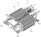
図1は、本実施形態に係るリアクトルの全体構成を示す斜視図であり、図2は、その分解斜視図である。本実施形態のリアクトルは、例えばハイブリッド自動車や電気自動車の駆動システム等で使用される大容量のリアクトルである。リアクトルは、これら自動車に搭載される電気回路の主要部品である。この電気回路は、リアクトルの他、IGBT等の半導体スイッチング素子を有する。リアクトルは、半導体スイッチング素子のオンオフが高速に行われることにより、外部電源から供給される電気エネルギーを磁気エネルギーに変換し、当該エネルギーの蓄積及び放出を繰り返し、電流や電圧を抑制する。
[1. First Embodiment]
[1-1. Schematic configuration]
FIG. 1 is a perspective view showing the overall configuration of the reactor according to the present embodiment, and FIG. 2 is an exploded perspective view thereof. The reactor according to the present embodiment is a large-capacity reactor used in, for example, a drive system for a hybrid vehicle or an electric vehicle. The reactor is the main component of the electric circuit mounted on these automobiles. This electric circuit includes a semiconductor switching element such as an IGBT in addition to a reactor. The reactor converts the electrical energy supplied from the external power source into magnetic energy by turning on and off the semiconductor switching element at high speed, repeatedly stores and releases the energy, and suppresses current and voltage.
リアクトルは、図1および図2に示すように、環状コア1と、環状コア1の一部の外周に巻回されたコイル5と、環状コア1の外周を覆い、環状コア1とコイル5とを絶縁する絶縁被覆部2を有している。
As shown in FIGS. 1 and 2, the reactor includes an annular core 1, a coil 5 wound around a part of the outer periphery of the annular core 1, an outer periphery of the annular core 1, and the annular core 1 and the coil 5. It has the insulation coating |
環状コア1は、環状の磁性体であり、環状の一部に一対の平行な直線部分と、これらの直線部分を繋ぐU字形状の連結部分とを有する。環状コア1のうち、コイル5が巻回された直線部分は、磁束が発生する脚部である。本実施形態の環状コア1の脚部は、図1に示す一対の平行に並んだコイル51a、51bに巻回された一対の直線状の部分である。脚部に磁束が発生するのは、コイル5に電流が流れるとコイル5を鎖交する磁束が発生するからである。コイル5が巻回されていないU字形状の連結部分は、脚部で発生した磁束が通過するヨーク部である。すなわち、ヨーク部は、一対の直線部分を繋ぐ。環状コア1内には、脚部で発生した磁束がヨーク部を通過することで、環状の閉じた磁気回路が形成される。
The annular core 1 is an annular magnetic body, and has a pair of parallel straight portions and a U-shaped connecting portion that connects these straight portions to a portion of the annular shape. In the annular core 1, the straight portion around which the coil 5 is wound is a leg portion where magnetic flux is generated. The legs of the annular core 1 of this embodiment are a pair of linear portions wound around a pair of
絶縁被覆部2は、環状コア1の外周を覆っており、全体として環状コア1と同じく、環状形状を有する。
The insulating
このようなリアクトルは、例えばアルミニウム合金等、熱伝導性が高く軽量な金属で形成された略直方体の収容スペースを有する放熱ケース(不図示)内に固定される。この固定のため、絶縁被覆部2の連結部21c、22dには固定部23a、23b、24a、24bが設けられており、この固定部23a、23b、24a、24bにネジを締結させてリアクトルが放熱ケースに固定される。放熱ケースが熱伝導性を有するのは、コイル5の通電により発生した熱を逃がすためである。
Such a reactor is fixed in a heat dissipation case (not shown) having a substantially rectangular parallelepiped housing space formed of a metal having high thermal conductivity and light weight such as an aluminum alloy. For this fixing, fixing
リアクトルと放熱ケースとの隙間には充填材が充填・固化され、充填樹脂部(不図示)が形成される。充填材には、リアクトルの放熱性能の確保及びリアクトルから放熱ケースへの振動伝搬の軽減のため、比較的柔らかく熱伝導性の高い樹脂が適している。 A filler is filled and solidified in the gap between the reactor and the heat radiating case to form a filled resin portion (not shown). As the filler, a resin that is relatively soft and has high thermal conductivity is suitable for ensuring the heat dissipation performance of the reactor and reducing the propagation of vibration from the reactor to the heat dissipation case.
[1−2.詳細構成]
次に、本実施形態のリアクトルの各構成について、詳細に説明する。環状コア1は、圧粉磁心、フェライト磁心、又は積層鋼板などの磁性体である。環状コア1は、複数の分割コアを有し、互いの分割コアが接着層1eを介して環状になるように接続されている。本実施形態の分割コアは、左右の脚部を構成するI字型コア1a、1bと、ヨーク部を構成する2つのU字型コア1c、1dである。
[1-2. Detailed configuration]
Next, each structure of the reactor of this embodiment is demonstrated in detail. The annular core 1 is a magnetic body such as a dust core, a ferrite core, or a laminated steel plate. The annular core 1 has a plurality of divided cores, and the divided cores are connected so as to be annular via the
I字型コア1a、1bおよびU字型コア1c、1dは、両端部に他の分割コアが接着する接着面を有する。これらI字型コア1a、1bとU字型コア1c、1dは、互いの接着面の間に介在された接着層1eによって環状になるように接続され、固定されている。本実施形態では、図2に示すように、I字型コア1a、1b、及びU字型コア1c、1dは、略四角形状の接着面の対向する一対の辺が面取りされ、丸みを帯びたR状になっており、互いに重ならないように直交させて接続されている。換言すると、図2では、I字型コア1a、1bのR状の辺は水平方向に延び、U字型コア1c、1dのR状の辺は鉛直方向に延びる。従って、分割コアの接着部分において、分割コア同士の対向する二辺のうち、少なくとも一方の辺はR状になっていない辺となる。
The I-shaped
接着層1eは、接着剤からなる。接着剤としては、特に限定されないが、熱硬化型の接着剤を用いることができ、例えば、エポキシ系、シリコーン系、アクリル系の接着剤が挙げられる。エポキシ系の接着剤は強度が高いので好ましい。熱硬化型接着剤の場合、高耐熱が要求されるのでガラス転移点が160℃以上の接着剤が好ましい。さらに、接着剤は、攪拌時に低粘度、通常の状態で高粘度の物性であるチクソ性を有することが好ましい。接着剤として1液性加熱硬化型接着剤を用いると、接着剤の塗布後加熱するまで硬化しないので取り扱いが容易である。また、2液性接着剤を用いて2種類の接着剤を混合し硬化させるようにしても良い。
The
なお、環状コア1の脚部とは、上記の通りコイル5が巻回される部分であり、本実施形態では、I字型コア1a、1bの他、U字型コア1c、1dの端部を含んでいる。環状コア1のヨーク部は、U字型コア1c、1dのうち、コイル5が巻回されていない曲線的な部分である。但し、コイル5の巻数によっては、I字型コア1a、1bのみを脚部とし、U字型コア1c、1dをヨーク部とすることもでき、分割コアのどの部分を脚部とし、ヨーク部とするかは設計により適宜変更可能である。
In addition, the leg part of the annular core 1 is a part around which the coil 5 is wound as described above. In this embodiment, in addition to the I-shaped
絶縁被覆部2は、環状コア1の外周を、絶縁性を有する材料により被覆している部材である。従って、絶縁被覆部2は、環状コア1の形状に倣って環状に形成されている。すなわち、絶縁被覆部2は、一対の直線部分とこれら一対の直線部分を繋ぐ連結部分とを有する。絶縁被覆部2の一部の外周にはコイル5が巻回されており、絶縁被覆部2は、環状コア1とコイル5とを絶縁する。
The
絶縁性を有する材料としては、樹脂が挙げられる。樹脂の種類としては、例えば、エポキシ樹脂、不飽和ポリエステル系樹脂、ウレタン樹脂、BMC(Bulk Molding Compound)、PPS(Polyphenylene Sulfide)、PBT(Polybutylene Terephthalate)等が挙げられる。これらの樹脂は、環状コア1組み立て時に加わる分割コア同士の押圧によって割れない強度を有する。本実施形態では、絶縁被覆部2を樹脂で構成された部材として説明するが、絶縁性を有する材料は、樹脂に限られず、絶縁性を有するものであれば他の材料を用いても良い。
Resin is mentioned as a material which has insulation. Examples of the resin include an epoxy resin, an unsaturated polyester resin, a urethane resin, BMC (Bulk Molding Compound), PPS (Polyphenylene Sulphide), and PBT (Polybutylene Terephthalate). These resins have a strength that does not break due to the pressure between the split cores applied when the annular core 1 is assembled. In the present embodiment, the insulating
絶縁被覆部2は、二分割されている。すなわち、絶縁被覆部2は、略U字形状の第1の分離体21と、略C字形状の第2の分離体22とを別々に成形しておき、互いの端部を突き合わせることで構成される。第1の分離体21と第2の分離体22とを別々に成形するのは、I字型コア1a、1bを内部に収容するため、及び、コイル5をはめ込むためである。
The
具体的には、第1の分離体21は、一対の筒状の直線部21a、21bと、これらの直線部21a、21bを繋ぐ連結部21cとを有する。第2の分離体22は、一対の筒状の直線部22a、22bと、これらの直線部22a、22bを繋ぐ連結部22dとを有する。第1の分離体21の直線部21a、21bは、第2の分離体22の直線部22a、22bと比べて長尺である。
Specifically, the
連結部21c、22dの内部には、U字型コア1c、1dがモールド成形法によって埋め込まれている。換言すれば、連結部21c、22dに覆われたU字型コア1c、1dの外周部分が連結部21c、22dの内周とフィットしている。
直線部21a、21b、22a、22bの内部には、I字型コア1a、1bが配置されている。直線部21a、21b、22a、22bの先端には開口部がそれぞれ設けられている。リアクトル組み立て時には、直線部21a、21bの開口部からI字型コア1a、1bの一端が挿入され、I字型コア1a、1bの他端が直線部22a、22bの開口部に挿入され、第1の分離体21と第2の分離体22の互いの開口部を突き合わせることで、環状コア1を覆う絶縁被覆部2を構成する。
I-shaped
図3は、本実施形態に係るリアクトルを分割コアの接着面と垂直方向に切断した断面図である。図4は、I字型コア1bとU字型コア1dの接着部分周辺の部分拡大断面斜視図である。但し、U字型コア1dは省略している。図5は、図3の丸い点線A部分の拡大図である。図6は、図3のB−B断面のうち、U字型コア1d側からI字型コア1b側を見たときの模式図である。
FIG. 3 is a cross-sectional view of the reactor according to the present embodiment cut in a direction perpendicular to the bonding surface of the split core. FIG. 4 is a partial enlarged cross-sectional perspective view of the periphery of the bonded portion between the I-shaped
図3〜図6に示すように、絶縁被覆部2は、分割コア間に挟み込まれた突起部4を有する。突起部4は分割コアの接着面と垂直な方向に所定の厚みを有しており、分割コア間が当該厚みの分離間している。すなわち、突起部4は、分割コアの接着面同士に接触し、分割コア間の接着層1eの厚みが突起部4の厚みより薄くなることを防止する。突起部4の厚みは、接着層1eの確保したい所定の膜厚により適宜設計する。
As shown in FIGS. 3 to 6, the insulating
このような突起部4は、図3に示すように、絶縁被覆部2の分割コア間を覆う内壁に設けられている。本実施形態では、各分割コア間において、環状コア1の内周側および外周側の部分にそれぞれ設けられている。具体的には、本実施形態では、分割コア間は4つあり、突起部4は、U字型コア1cとI型コア1a、1bの間、および、U字型コア1dとI字型コア1a、1bの間に挟み込まれるように計8カ所設けられている。突起部4の構成は各分割コア間で同様であるので、代表してI字型コア1bとU字型コア1dの接着部分周辺を示したのが図4である。
As shown in FIG. 3, such a protruding
突起部4について、図4〜図6を用いてさらに詳細に説明する。突起部4は、絶縁被覆部2の分割コアの外周を覆う部分と一体成形されている。すなわち、突起部4は、U字型コア1c、1dをモールドする際の樹脂により構成されており、絶縁被覆部2のうち、分割コアの外周を覆う部分である直線部21a、21b、22a、22bの内壁から、直線部21a、21b、22a、22bの幅方向の内寸を狭めるように突き出ている。換言すると、突起部4は、直線部21a、21b、22a、22bと継ぎ目がなく、一続きに形成されたものである。
The
また、図4及び図6に示すように、突起部4は、I字型コア1b、U字型コア1dの接着面と平行に、すなわち分割コア1b、1dの幅方向と直交する方向に縦長に伸びている。なお、図6では突起部4と接着層1eの間には隙間があるが、接着層1eで分割コア間の両サイドの突起部4を隙間なく繋いでも良い。
Further, as shown in FIGS. 4 and 6, the
また、突起部4は、その先端側よりも基端側が拡がった形状を有している。換言すれば、突起部4は、その基端側から先端側にかけて窄んでいる。これにより、絶縁被覆部2を成形するための金型内に樹脂を充填した際に、当該金型内の突起部4を形成する部分に樹脂が充填されやすくなる。本実施形態では、図3〜図5に示すように、突起部4の一面はU字型コア1dの角部分の曲率を有する形状であり、U字型コア1dの角部分を、例えば、2mm程度の曲率半径とする。
Further, the
図2に示すように、連結部21c、22dには、環状コア1を放熱ケースに固定するための固定部23a、23b、24a、24bが設けられている。固定部23a、23b、24a、24bは、連結部21c、22dの表面から突出し、その先端にリアクトルを放熱ケースに固定するためのネジ挿入穴25a、25b、26a、26bが設けられている。ネジ挿入穴26a、26bにはナット28a、28bがはめ込まれている。リアクトルは、ネジ挿入穴25a、25b、26a、26bにネジを差し込んで、放熱ケースのネジ穴に締結することで、放熱ケースに固定される。
As shown in FIG. 2, the connecting
連結部21cの固定部23a、23bは、金具であり、U字型コア1cと共にモールド成形法により、ネジ挿入穴24a、24bが露出するようにして一端部が連結部21cに埋め込まれている。一方、連結部22dの固定部24a、24bは、樹脂で構成されている。本実施形態では、固定部24a、24bは、第2の分離体22を成形する金型に樹脂を流し込んで成形されており、連結部22dとの間に継ぎ目がない。従って、第2の分離体22は、直線部22a、22b、連結部22d、固定部24a、24b、および突起部4が同じ樹脂により一続きに構成された単一の部材である。また、第1の分離体21は、直線部21a、21b、連結部21c、および突起部4が同じ樹脂により一続きに構成された単一の部材と、金具からなる固定部23a、23bとで構成された部材である。
The fixing
連結部21cの表面には、他の部材を接続可能なコネクタ8が設けられている。本実施形態では、温度センサ9が取り付けられている。温度センサ9は、温度検出部9aと、温度検出部9aに接続されたリード線9bとからなる。温度検出部9aは、例えば、後述のコイル51a、51bの間に配置され、リアクトル内部の温度を検出する。リード線9bはコネクタ8に取り付けられ、温度検出部9aが検出した温度情報をリアクトル外部に伝達する。温度センサ9としては、例えば、温度変化に対して電気抵抗が変化するサーミスタを用いることができるが、これに限定されない。
On the surface of the connecting
コイル5は、絶縁被覆を有する導線である。本実施形態では、コイル5は、平角線のエッジワイズコイルである。但し、コイル5の線材や巻き方は平角線のエッジワイズコイルに限定されず、他の形態であっても良い。コイル5は、環状コア1の脚部を構成する分割コアの外周に巻回されている。より具体的には、本実施形態では、コイル5は、左右のコイル51a、51bを有する。これらのコイル51a、51bは絶縁被覆部2の一対の直線部分21a、21b、22a、22bの外周に巻回されている。
The coil 5 is a conducting wire having an insulating coating. In the present embodiment, the coil 5 is a flat wire edgewise coil. However, the wire material and winding method of the coil 5 are not limited to the rectangular wire edgewise coil, and may be in other forms. The coil 5 is wound around the outer periphery of the split core that constitutes the leg portion of the annular core 1. More specifically, in the present embodiment, the coil 5 includes left and
コイル51a、51bは、エナメル被覆した1本の銅線によってそれぞれ構成されている。コイル51aは端部52a、53aを有し、コイル51bは、端部52b、53bを有する。一方の端部52a、52bは第1の分離体21側に引き出され、他方の端部53a、53bは第2の分離体側に引き出されている。端部52a、52b、53a、53bは、バスバー(不図示)と接合され、バスバーを介して外部電源(不図示)と接続される。この外部電源から電力供給されると、コイル51a、51bに電流が流れてコイル51a、51bを突き抜ける磁束が発生し、環状コア1内に閉じた磁気回路が形成される。
The
なお、本実施形態では、コイル51a、51bの両端部52a、52b、53a、53bをそれぞれ引き出すようにしたが、一方のコイル51aの端部と他方のコイル51bの端部に連結しても良い。例えば、端部52a、52bが互いに連結され、端部53a、53bの一方から電力供給を受け、他方の端部53a、53bから外部に電流を流すようにしても良い。
In the present embodiment, both
[1−3.作用効果]
(1)本実施形態のリアクトルは、複数の分割コア1a〜1dが所定の膜厚を有する接着層1eを介して互いに接続された環状コア1と、環状コア1の外周を覆う絶縁被覆部2と、を備え、絶縁被覆部2は、分割コア1a〜1d間に挟み込まれた突起部4を有するようにした。これにより、突起部4の厚みの分だけ分割コア同士を接着する接着剤の膜厚、すなわち接着層1eの厚みを確保することができる。従って、突起部4により、接着剤の膜厚を所望の厚さにコントロールすることができ、所定の厚みの接着層1eを得ることができる。また、突起部4は絶縁被覆部2の構成としているので、接着剤にフィラーを含有させる必要がなく、製造コストを削減することができる。
[1-3. Effect]
(1) The reactor according to the present embodiment includes an annular core 1 in which a plurality of divided
(2)絶縁被覆部2は、分割コア間を覆う内壁を有し、突起部4は、絶縁被覆部2の内壁から一続きに突き出ているようにした。これにより、突起部4を別途作製し、絶縁被覆部2の内周に取り付ける場合に比べて、製造の工数及び製造コストを削減することができる。
(2) The
(3)突起部4は、樹脂からなるようにした。これにより、樹脂が強度を有しているため、分割コア同士を接着加圧しても、突起部4の厚みより分割コア間の距離が小さくなるのを抑制することができる。従って、接着剤1eの膜厚を確保することができる。
(3) The
(4)突起部4は、先端側よりも基端側が拡がった形状を有するようにした。これにより、絶縁被覆部2を成形する金型と一緒に突起部4を成形する場合において、当該金型の突起部4を形成する部分に樹脂等の絶縁被覆部2の材料が流れ込みやすくなり、突起部4を別途作製して取り付ける場合と比べて、製造工数及び製造コストを削減することができる。
(4) The
(5)分割コアは、他の分割コアと接続される接着面を備え、接着面の対向する一対の辺が面取りされた辺であり、環状コア1は、分割コアの一対の辺が、当該分割コアと接着される他の分割コアの面取りされた一対の辺と直交するように前記分割コアを接続して形成するようにした。これにより、分割コア同士の接続部分において、一方の分割コアの面取りされた辺と、他方の分割コアの面取りされていない辺とが対向することになる。すなわち、分割コア同士の対向する二辺のうち、少なくとも一方の辺が、分割コアの角が直角になっている部分である面取りされていない辺となる。このため、突起部4は、その先端のみならず基端側も挟み込みやすくなり、接着層1eの膜厚のコントロールがしやすくなる。
(5) The split core is provided with an adhesive surface connected to another split core, and a pair of sides facing the adhesive surface is chamfered, and the annular core 1 has a pair of sides of the split core. The split cores are connected and formed so as to be orthogonal to a pair of chamfered sides of another split core to be bonded to the split core. Thereby, in the connection part of split cores, the chamfered side of one split core and the non-chamfered side of the other split core face each other. That is, at least one of the two opposing sides of the split cores is a non-chamfered side that is a portion where the corners of the split core are perpendicular. For this reason, it becomes easy to pinch not only the front-end | tip part but the base end side, and it becomes easy to control the film thickness of the
[2.第2の実施形態]
[2−1.構成]
第2の実施形態について、図7を用いて説明する。第2の実施形態は、第1の実施形態と基本構成は同じである。よって、第1の実施形態と異なる点のみを説明し、第1の実施形態と同じ部分については同じ符号を付して詳細な説明は省略する。
[2. Second Embodiment]
[2-1. Constitution]
A second embodiment will be described with reference to FIG. The basic configuration of the second embodiment is the same as that of the first embodiment. Therefore, only a different point from 1st Embodiment is demonstrated, the same code | symbol is attached | subjected about the same part as 1st Embodiment, and detailed description is abbreviate | omitted.
図7は、I字型コア1bとU字型コア1dの接着部分周辺の部分拡大断面図である。なお、他の接着部分については、I字型コア1bとU字型コア1dの接着部分と同様であるので説明は適宜省略する。
FIG. 7 is a partially enlarged cross-sectional view of the periphery of the bonded portion between the I-shaped
第2の実施形態では、環状コア1は、分割コア間にスペーサ1fを挟んで構成されている。換言すれば、スペーサ1fは、その両面に接着層1eを介して分割コア間に配置される。スペーサ1fは、例えばセラミックなどで構成され、分割コア間に所定幅の磁気的なギャップを与える。
In the second embodiment, the annular core 1 is configured with a
具体的には、本実施形態のスペーサ1fは、所定の厚みを有する平板である。この板状のスペーサ1fは、U字型コア1cとI字型コア1a、1bの接着面間、および、U字型コア1dとI字型コア1a、1bの接着面間にそれぞれ配置されている。スペーサ1fは、U字型1cとI字型コア1a、1bとの間、および、U字型コア1dとI字型コア1a、1bとの間に所定幅の磁気的なギャップを与え、リアクトルのインダクタンス低下を防止する。例えば、高電流を流した場合のインダクタンス低下に効果的である。
Specifically, the
本実施形態の絶縁被覆部2は、分割コアとスペーサ1fとの間に挟み込まれた突起部4を備える。図7に示すように、突起部4は、スペーサ1fの両面に位置する接着層1eの厚みを確保するものであり、具体的には、絶縁被覆部2は、互いに接続される分割コアの一方とスペーサ1fとの間に挟み込まれた第1の突起部4aと、互いに接続される分割コアの他方とスペーサ1fとの間に挟み込まれた第2の突起部4bとを備える。なお、互いに接続される分割コアとは、U字型コア1cとI字型コア1a若しくはI字型コア1b、又は、U字型コア1dとI字型コア1a若しくはI字型コア1bである。
The
第1の突起部4aは、U字型コア1c、1dの接着面の一部を覆うように、絶縁被覆部2の内壁から一続きに突き出ている。第1の突起部4aの背面には、スペーサ1fが接触するように配置されている。このスペーサ1fとU字型コア1c、1dとの間には、接着層1eが介在しており、その膜厚は、第1の突起部4aの厚み分確保できる。スペーサ1f上には、第2の突起部4bが絶縁被覆部2の内壁から一続きに突き出ており、当該第2の突起部4bが接するように配置され、I字型コア1a、1bとスペーサ1fとの間に介在する接着層1eの膜厚が、第2の突起部4bの厚み分確保できる。
The
第1の突起部4aは、絶縁被覆部2のうち、U字型コア1c、1dを被覆する部分に設けられ、第2の突起部4bは、絶縁被覆部2のうち、I字型コア1a、1bを被覆する部分に設けられる。第1の突起部4aと第2の突起部4bをどのように設けるかは、適宜設計により変更できる。
The
例えば、絶縁被覆部2の構成を第1の実施形態と同様に第1の分離体21と第2の分離体22とで構成する場合には、第1の分離体21と第2の分離体22をさらに細分化して成形しておく。すなわち、連結部21cと直線部21a、21b、及び、連結部22dと直線部22a、22bを、それぞれ分離して成形しておく。その際、第2の分離体22を例にして説明すると、樹脂モールド成形により、連結部22dと第1の突起部4aを一続きに成形し、直線部22a、22bと第2の突起部4bを一続きに成形しておく。そして、直線部22a、22bの端部と連結部22dの端部とを突き合わせて第2の分離体22を構成する。直線部22a、22bの端部と連結部22dの端部は、一方が他方に嵌まるように段差等の取り付け部を設けるようにしても良い。
For example, when the configuration of the insulating
或いは、第1の実施形態では絶縁被覆部2を二分割した第1の分離体21と第2の分離体22とで構成したが、図8(a)、(b)に示すように、I字型コア1a、1bを被覆する一対の直線部20a、20bと、この一対の直線部20a、20bのU字型コア1c側のそれぞれの端部を連結部21cにより連結し、一対の直線部20a、20bのU字型コア1d側のそれぞれの端部を連結部22dにより連結して構成しても良い。
Alternatively, in the first embodiment, the first insulating
換言すると、第1の実施形態の分離されていた直線部21aと直線部21bを一つの直線部20aとし、同様に、直線部22aと直線部22bを一つの直線部20bとしても良い。この場合、U字型コア1c、1dを樹脂モールドすることにより、連結部21c、22dを成形するとともに、第1の突起部4aをU字型コア1c、1dの接着面の一部を覆うように設ける。また、I字型コア1a、1bを樹脂モールドすることにより、直線部20a、20bを成形するとともに、第2の突起部4bをI字型コア1a、1bの接着面の一部を覆うように設ける。
In other words, the
リアクトルの組み立て時には、第1の突起部4a又は第2の突起部4bは、スペーサ1fを他の突起部4a、4bに押しつけるための押圧治具として機能する。
When the reactor is assembled, the
なお、図7では、分割コア1b、1dの対向する二辺が共に面取りされたR状の辺となっているが、第1の実施形態と同様に、分割コアの接着面の対向する一対の辺が面取りされた辺であり、環状コア1は、分割コアの前記一対の辺が、当該分割コアと接着される前記分割コアの前記一対の辺と直交するように前記分割コアを接続して形成しても良い。
In FIG. 7, the two opposite sides of the
[2−2.作用効果]
本実施形態のリアクトルは、複数の分割コアを所定の膜厚を有する接着層1eを介して互いに接続して形成された環状コア1と、環状コア1の外周を覆う絶縁被覆部2と、を備え、環状コア1は、両面に接着層1eを介して分割コア間に配置されるスペーサ1fを備え、絶縁被覆部2は、分割コアとスペーサ1fとの間に挟み込まれた突起部4を備えるようにした。これにより、分割コアとスペーサ1fとの間が、突起部4の厚み分離間することができるので、分割コアとスペーサ1fとの間に介在する接着層1eの膜厚を突起部4の厚み分確保することができる。
[2-2. Effect]
The reactor of the present embodiment includes an annular core 1 formed by connecting a plurality of divided cores to each other via an
特に、絶縁被覆部2は、互いに接続される分割コアの一方とスペーサ1fとの間に挟み込まれる第1の突起部4aと、互いに接続される分割コアの他方とスペーサ1fとの間に挟み込まれる第2の突起部4bと、を備えるようにしたので、スペーサの両側に位置する接着層1eの膜厚を所定の膜厚にすることができる。
In particular, the insulating
[3.他の実施形態]
本発明は、第1および第2の実施形態に限定されるものではなく、下記に示す他の実施形態も包含する。また、本発明は、下記の他の実施形態を組み合わせた形態も包含する。
[3. Other Embodiments]
The present invention is not limited to the first and second embodiments, and includes other embodiments described below. In addition, the present invention also includes a combination of the following other embodiments.
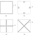
(1)第1および第2の実施形態では、突起部4は各分割コア間に環状コア1の閉磁路の内側及び外側部分の2カ所にそれぞれ設けられているが、閉磁路の内周部分又は外周部分だけでも良い。また、第2の実施形態の変形例として、図8(a)に示すように、I字型コア1a、1bを樹脂モールドして成形された直線部20a、20bにのみ突起部4、すなわち第2の突起部4bを設けても良いし、図8(b)に示すように、第1の突起部4a、第2の突起部4bを、直線部20a、20b又は連結部21c、22dの何れかに補完し合うように設けても良い。また、これらに限定されず、突起部4は絶縁被覆部2の分割コア間の断面図であって突起部4の設置態様を示す図9のような形態でも良い。すなわち、図9(a)に示すように、分割コアの接着面の全周囲と接するように、絶縁被覆部2の内周に環状に設けても良いし、図9(b)に示すように、分割コアの接着面の各辺に一部分が接するように、絶縁被覆部2の内周に点状に設けても良い。さらに、図9(c)、(d)に示すように、絶縁被覆部2の内周に十(プラス)字状、X字状に設けても良い。なお、図9(a)〜(d)の点線部は、絶縁被覆部2の内壁のうち、突起部4が設けられていない箇所の輪郭を示している。
(1) In the first and second embodiments, the
(2)第1および第2の実施形態では、突起部4は直線部21a、21b、22a、22bの内部に設けたが、これに限定されない。分割コア間に挟み込むことができ、環状コア1の外周を覆う絶縁被覆部2の内周であれば、設置箇所は限定されない。例えば、連結部21c、22dの内周に設けてもよい。
(2) In the first and second embodiments, the
(3)分割コア間にスペーサ1fを配置する第2の実施形態の変形例として、突起部を図10に示すような突起部40aとしても良い。突起部40aは、スペーサ1fの両面に位置する接着層1eの厚みを確保するものであり、第1の突起41と第2の突起42とを有している。第1の突起41及び第1の突起42は、第1の実施形態の突起部4と同様に、絶縁被覆部2の直線部21a、21b、22a、22b内壁から当該直線部21a、21b、22a、22bの左右の幅方向を狭めるように突き出ている。
(3) As a modification of the second embodiment in which the
第1の突起41は、U字型コア1dとスペーサ1fとの間に挟み込まれており、両者の間の接着層1eの膜厚を確保する。換言すれば、第1の突起41はスペーサ1fの端部と重なり合う。
The
第2の突起42は、第1の突起41と隣接して設けられ、絶縁被覆部2の内壁から突き出ているが、第1の突起41よりは突き出ていない。換言すれば、突起部40aは階段形状になっており、図10に示すように、第2の突起42はスペーサ1fと分割コア1b、1dの接着面方向に隣接する。このように第2の突起42を第1の突起41より突き出す長さが短いのは、スペーサ1fを直線部21a、21b、22a、22bから挿入し、第1の突起41と重なるように配置しやすくするためである。
The
第2の突起42の厚みはスペーサ1fの板厚より厚く、第2の突起42はI字型コア1bの接着面と接している。従って、I字型コア1bとスペーサ1fとの間の接着層1eの膜厚は、第2の突起42の厚みからスペーサ1fの厚みを差し引いた分となり、I字型コア1bとスペーサ1fとの間の接着層1eの膜厚を確保することができる。
The thickness of the
(4)分割コア間にスペーサ1fを配置する第2の実施形態の変形例として、突起部を図11に示すような突起部40bとしても良い。前記(3)の変形例と基本構成は同じであり、前記(3)の変形例と異なる点のみを説明し、同じ部分については同じ符号を付して詳細な説明は省略する。なお、突起部40bの構成は各分割コア間で同様であるので、代表してI字型コア1bとU字型コア1dの接着部分を例にして、図11に示して説明する。
(4) As a modification of the second embodiment in which the
突起部40bは、第1の突起41と、第2の突起42bとを有する。第1の突起41は、突起部40aと構成は同じであり、互いに接続される分割コアの一方のU字型コア1dとスペーサ1fとの間に挟み込まれている。図11に示すように、第2の突起42bは、絶縁被覆部2の内壁から第1の突起41と同じ長さ分だけ突き出ており、他方の分割コアであるI字型コア1bとスペーサ1fとの間に挟み込まれている。第2の突起42bは、第1の突起41から離間して設けられており、その距離は、スペーサ1fの板厚と同じである。すなわち、スペーサ1fは、第1の突起41と第2の突起42bに挟まれるようにして位置決めされている。
The
なお、スペーサ1fが直線部21a、21b、22a、22bの開口部から挿入して第1の突起41と第2の突起42bの間に差し込むためには、例えば、突起部40bを環状コア1の内周側又は外周側の何れか一方にのみ設け、他方に設けないようにすれば良い。このようにすることで、第2の突起42bが障壁となることなく、スペーサ1fを第1の突起41に重ねて配置することができる。
In order to insert the
このように、突起部40bの第1の突起41と第2の突起42bとにより、分割コア間にスペーサ1fを配置する場合であっても、スペーサ1fの両面の接着層1eの膜厚をコントロールすることができるとともに、第1の突起41と第2の突起42bがスペーサ1fの位置決め部材としても機能し、分割コア間のスペーサの配置が正確になり、製品間のバラツキを少なくすることができる。
As described above, the
(5)第1および第2の実施形態では、環状コア1の脚部を構成するI字型コア1a、1bは単一のコアで構成されているが、二以上の小型のI字型コアを突き合わせて脚部を構成してもよい。この場合、小型のI字型コア間に挟み込まれる突起部4を絶縁被覆部2の内部の複数箇所に設けてもよい。
(5) In the first and second embodiments, the I-shaped
(6)第1および第2の実施形態では、突起部4は、U字型コア1c、1dの樹脂モールドにより直線部21a、21b、22a、22bと継ぎ目がないように設けたが、突起部4を別途作製し、直線部21a、21b、22a、22bの内側に接着剤等により取り付けてもよい。
(6) In the first and second embodiments, the
(7)第1および第2の実施形態では、突起部4は、基端から先端にかけて窄んだ形状として丸みのある形状を有しているが、丸みの部分を直線状にして角張らせても良いし、階段状にしても良い。
(7) In the first and second embodiments, the
(8)第1および第2の実施形態では、環状コア1を構成するために、分割コアとしてU字型コア及びI字型コア、又はE字型コアを用いたが、これに限定されない。すなわち、環状コア1は、分割コアを複数突き合わせて構成されたものであればよく、これらの他にも分割コアとして、E字型コア、T字型コアその他の環状コア1を構成可能な形状を有するコアを用いることができる。 (8) In the first and second embodiments, the U-shaped core and the I-shaped core or the E-shaped core are used as the split cores in order to form the annular core 1, but the present invention is not limited to this. That is, the annular core 1 only needs to be configured by abutting a plurality of divided cores. In addition to these, a shape capable of configuring an E-shaped core, a T-shaped core, and other annular cores 1 as the divided cores. A core having can be used.
(9)第1および第2の実施形態では、リアクトルは1つで説明したが、複数のリアクトルを各脚部が平行になるように並列にしたものに本発明を適用しても良い。 (9) In the first and second embodiments, one reactor has been described. However, the present invention may be applied to a configuration in which a plurality of reactors are arranged in parallel so that each leg portion is parallel.
1 環状コア
1a、1b I字型コア
1c、1d U字型コア
1e 接着層
1f スペーサ
2 絶縁被覆部
20a、20b 直線部
21 第1の分離体
21a、21b 直線部
21c 連結部
23a、23b 固定部
25a、25b ネジ挿入穴
22 第2の分離体
22a、22b 直線部
22d 連結部
24a、24b 固定部
26a、26b ネジ挿入穴
28a、28b ナット
4 突起部
4a 第1の突起部
4b 第2の突起部
40a 突起部
41 第1の突起
42 第2の突起
40b 突起部
42b 第2の突起
5 コイル
51a、51b コイル
52a、52b 端部
53a、53b 端部
8 コネクタ
9 温度センサ
9a 温度検出部
9b リード線
DESCRIPTION OF SYMBOLS 1 cyclic |
Claims (11)
前記環状コアの外周を覆う絶縁被覆部と、
を備え、
前記絶縁被覆部は、前記分割コア間に挟み込まれた突起部を有すること、
を特徴とするリアクトル。 An annular core formed by connecting a plurality of divided cores to each other through an adhesive layer having a predetermined film thickness;
An insulating coating covering the outer periphery of the annular core;
With
The insulating coating has a protrusion sandwiched between the divided cores;
Reactor characterized by.
前記突起部は、前記内壁から一続きに突き出ていること、
を特徴とする請求項1に記載のリアクトル。 The insulating covering portion has an inner wall that covers between the divided cores,
The protrusion protrudes continuously from the inner wall;
The reactor according to claim 1.
を特徴とする請求項1又は請求項2に記載のリアクトル。 The protrusion is made of resin;
The reactor according to claim 1 or 2, characterized in that.
を特徴とする請求項1〜3の何れか1項に記載のリアクトル。 The protruding portion has a shape in which the proximal end side is wider than the distal end side,
The reactor of any one of Claims 1-3 characterized by these.
前記接着面の対向する一対の辺が面取りされた辺であり、
前記環状コアは、
前記分割コアの前記一対の辺が、当該分割コアと接着される前記分割コアの前記一対の辺と直交するように前記分割コアを接続して形成されていること、
を特徴とする請求項1〜4の何れか1項に記載のリアクトル。 The split core includes an adhesive surface connected to another split core,
A pair of sides facing the adhesive surface is a chamfered side,
The annular core is
The pair of sides of the split core are formed by connecting the split cores so as to be orthogonal to the pair of sides of the split core bonded to the split core;
The reactor of any one of Claims 1-4 characterized by these.
前記環状コアの外周を覆う絶縁被覆部と、
を備え、
前記環状コアは、両面に前記接着層を介して前記分割コア間に配置されるスペーサを備え、
前記絶縁被覆部は、前記分割コアと前記スペーサとの間に挟み込まれた突起部を備えること、
を特徴とするリアクトル。 An annular core formed by connecting a plurality of divided cores to each other through an adhesive layer having a predetermined film thickness;
An insulating coating covering the outer periphery of the annular core;
With
The annular core includes spacers disposed between the split cores on both sides via the adhesive layer,
The insulating coating portion includes a protrusion sandwiched between the split core and the spacer;
Reactor characterized by.
互いに接続される前記分割コアの一方と前記スペーサとの間に挟み込まれた第1の突起部と、
前記互いに接続される前記分割コアの他方と前記スペーサとの間に挟み込まれた第2の突起部と、
を備えること、
を特徴とする請求項6に記載のリアクトル。 The insulating covering portion is
A first protrusion sandwiched between one of the divided cores connected to each other and the spacer;
A second protrusion sandwiched between the spacer and the other of the split cores connected to each other;
Providing
The reactor according to claim 6.
前記突起部は、前記内壁から一続きに突き出ていること、
を特徴とする請求項6又は請求項7に記載のリアクトル。 The insulating covering portion has an inner wall that covers between the divided cores,
The protrusion protrudes continuously from the inner wall;
The reactor of Claim 6 or Claim 7 characterized by these.
を特徴とする請求項6〜8の何れか1項に記載のリアクトル。 The protrusion is made of resin;
The reactor of any one of Claims 6-8 characterized by these.
を特徴とする請求項6〜9の何れか1項に記載のリアクトル。 The protruding portion has a shape in which the proximal end side is wider than the distal end side,
The reactor of any one of Claims 6-9 characterized by these.
前記接着面の対向する一対の辺が面取りされた辺であり、
前記環状コアは、
前記分割コアの前記一対の辺が、当該分割コアと接着される前記分割コアの前記一対の辺と直交するように前記分割コアを接続して形成されていること、
を特徴とする請求項6〜10の何れか1項に記載のリアクトル。 The split core includes an adhesive surface connected to another split core,
A pair of sides facing the adhesive surface is a chamfered side,
The annular core is
The pair of sides of the split core are formed by connecting the split cores so as to be orthogonal to the pair of sides of the split core bonded to the split core;
The reactor of any one of Claims 6-10 characterized by these.
Priority Applications (1)
| Application Number | Priority Date | Filing Date | Title |
|---|---|---|---|
| JP2014262762A JP6541967B2 (en) | 2014-12-25 | 2014-12-25 | Reactor |
Applications Claiming Priority (1)
| Application Number | Priority Date | Filing Date | Title |
|---|---|---|---|
| JP2014262762A JP6541967B2 (en) | 2014-12-25 | 2014-12-25 | Reactor |
Publications (2)
| Publication Number | Publication Date |
|---|---|
| JP2016122764A true JP2016122764A (en) | 2016-07-07 |
| JP6541967B2 JP6541967B2 (en) | 2019-07-10 |
Family
ID=56328962
Family Applications (1)
| Application Number | Title | Priority Date | Filing Date |
|---|---|---|---|
| JP2014262762A Active JP6541967B2 (en) | 2014-12-25 | 2014-12-25 | Reactor |
Country Status (1)
| Country | Link |
|---|---|
| JP (1) | JP6541967B2 (en) |
Cited By (1)
| Publication number | Priority date | Publication date | Assignee | Title |
|---|---|---|---|---|
| JP2020027806A (en) * | 2018-08-09 | 2020-02-20 | 株式会社タムラ製作所 | Reactor |
Citations (14)
| Publication number | Priority date | Publication date | Assignee | Title |
|---|---|---|---|---|
| JPS588926U (en) * | 1981-07-10 | 1983-01-20 | 株式会社デンソー | Integrated core molded ignition coil |
| JP2003086431A (en) * | 2001-06-29 | 2003-03-20 | Tabuchi Electric Co Ltd | Electromagnetic inductor |
| JP2005302900A (en) * | 2004-04-08 | 2005-10-27 | Sht Corp Ltd | Coil device and its manufacturing method |
| JP2008288416A (en) * | 2007-05-18 | 2008-11-27 | Sht Corp Ltd | Coil unit |
| JP2009032922A (en) * | 2007-07-27 | 2009-02-12 | Toyota Motor Corp | Reactor core and reactor |
| JP2010232272A (en) * | 2009-03-26 | 2010-10-14 | Seiko Epson Corp | Transformer |
| WO2012111153A1 (en) * | 2011-02-18 | 2012-08-23 | トヨタ自動車株式会社 | Reactor |
| JP2012191140A (en) * | 2011-03-14 | 2012-10-04 | Tamura Seisakusho Co Ltd | Core module, coil device, and method for manufacturing core module |
| JP2013191803A (en) * | 2012-03-15 | 2013-09-26 | Tamura Seisakusho Co Ltd | Reactor and method for manufacturing reactor |
| JP2013197567A (en) * | 2012-03-23 | 2013-09-30 | Tamura Seisakusho Co Ltd | Reactor and manufacturing method of the same |
| JP2013211371A (en) * | 2012-03-30 | 2013-10-10 | Toyota Motor Corp | Reactor |
| JP2013211334A (en) * | 2012-03-30 | 2013-10-10 | Hitachi Metals Ltd | Composite magnetic core, reactor and power supply unit |
| JP2014033039A (en) * | 2012-08-02 | 2014-02-20 | Toyota Motor Corp | Manufacturing apparatus and manufacturing method of reactor |
| JP2014123680A (en) * | 2012-12-21 | 2014-07-03 | Toyota Motor Corp | Reactor and method of manufacturing the same |
-
2014
- 2014-12-25 JP JP2014262762A patent/JP6541967B2/en active Active
Patent Citations (14)
| Publication number | Priority date | Publication date | Assignee | Title |
|---|---|---|---|---|
| JPS588926U (en) * | 1981-07-10 | 1983-01-20 | 株式会社デンソー | Integrated core molded ignition coil |
| JP2003086431A (en) * | 2001-06-29 | 2003-03-20 | Tabuchi Electric Co Ltd | Electromagnetic inductor |
| JP2005302900A (en) * | 2004-04-08 | 2005-10-27 | Sht Corp Ltd | Coil device and its manufacturing method |
| JP2008288416A (en) * | 2007-05-18 | 2008-11-27 | Sht Corp Ltd | Coil unit |
| JP2009032922A (en) * | 2007-07-27 | 2009-02-12 | Toyota Motor Corp | Reactor core and reactor |
| JP2010232272A (en) * | 2009-03-26 | 2010-10-14 | Seiko Epson Corp | Transformer |
| WO2012111153A1 (en) * | 2011-02-18 | 2012-08-23 | トヨタ自動車株式会社 | Reactor |
| JP2012191140A (en) * | 2011-03-14 | 2012-10-04 | Tamura Seisakusho Co Ltd | Core module, coil device, and method for manufacturing core module |
| JP2013191803A (en) * | 2012-03-15 | 2013-09-26 | Tamura Seisakusho Co Ltd | Reactor and method for manufacturing reactor |
| JP2013197567A (en) * | 2012-03-23 | 2013-09-30 | Tamura Seisakusho Co Ltd | Reactor and manufacturing method of the same |
| JP2013211371A (en) * | 2012-03-30 | 2013-10-10 | Toyota Motor Corp | Reactor |
| JP2013211334A (en) * | 2012-03-30 | 2013-10-10 | Hitachi Metals Ltd | Composite magnetic core, reactor and power supply unit |
| JP2014033039A (en) * | 2012-08-02 | 2014-02-20 | Toyota Motor Corp | Manufacturing apparatus and manufacturing method of reactor |
| JP2014123680A (en) * | 2012-12-21 | 2014-07-03 | Toyota Motor Corp | Reactor and method of manufacturing the same |
Cited By (3)
| Publication number | Priority date | Publication date | Assignee | Title |
|---|---|---|---|---|
| JP2020027806A (en) * | 2018-08-09 | 2020-02-20 | 株式会社タムラ製作所 | Reactor |
| US11315720B2 (en) | 2018-08-09 | 2022-04-26 | Tamura Corporation | Reactor |
| JP7148313B2 (en) | 2018-08-09 | 2022-10-05 | 株式会社タムラ製作所 | Reactor |
Also Published As
| Publication number | Publication date |
|---|---|
| JP6541967B2 (en) | 2019-07-10 |
Similar Documents
| Publication | Publication Date | Title |
|---|---|---|
| JP5626466B2 (en) | Reactor and manufacturing method thereof | |
| US10096420B2 (en) | Reactor | |
| JP6280592B2 (en) | Reactor | |
| JP2016066721A (en) | Reactor | |
| CN110494940B (en) | Electric reactor | |
| JP6106646B2 (en) | Reactor | |
| JP6774726B2 (en) | Reactor | |
| JP6651879B2 (en) | Reactor | |
| JP6482271B2 (en) | Reactor | |
| JP6541967B2 (en) | Reactor | |
| JP6490392B2 (en) | Reactor | |
| JP6560580B2 (en) | Reactor | |
| JP6106645B2 (en) | Reactor | |
| JP6660800B2 (en) | Reactor | |
| JP2016143835A (en) | Reactor | |
| JP7189655B2 (en) | coil and reactor | |
| JP6570982B2 (en) | Reactor | |
| US20210043368A1 (en) | Reactor | |
| JP6578187B2 (en) | Reactor | |
| JP2020035806A (en) | Reactor | |
| JP6578157B2 (en) | Resin mold core, reactor | |
| JP2016066752A (en) | Reactor | |
| JP7377250B2 (en) | reactor | |
| CN111656470B (en) | Electric reactor | |
| WO2016060000A1 (en) | Reactor |
Legal Events
| Date | Code | Title | Description |
|---|---|---|---|
| A621 | Written request for application examination |
Free format text: JAPANESE INTERMEDIATE CODE: A621 Effective date: 20171018 |
|
| A977 | Report on retrieval |
Free format text: JAPANESE INTERMEDIATE CODE: A971007 Effective date: 20181030 |
|
| A131 | Notification of reasons for refusal |
Free format text: JAPANESE INTERMEDIATE CODE: A131 Effective date: 20181106 |
|
| A521 | Request for written amendment filed |
Free format text: JAPANESE INTERMEDIATE CODE: A523 Effective date: 20181227 |
|
| TRDD | Decision of grant or rejection written | ||
| A01 | Written decision to grant a patent or to grant a registration (utility model) |
Free format text: JAPANESE INTERMEDIATE CODE: A01 Effective date: 20190528 |
|
| A61 | First payment of annual fees (during grant procedure) |
Free format text: JAPANESE INTERMEDIATE CODE: A61 Effective date: 20190612 |
|
| R150 | Certificate of patent or registration of utility model |
Ref document number: 6541967 Country of ref document: JP Free format text: JAPANESE INTERMEDIATE CODE: R150 |