EP4056776A1 - Sanitärartikelanordnung - Google Patents
Sanitärartikelanordnung Download PDFInfo
- Publication number
- EP4056776A1 EP4056776A1 EP21162019.0A EP21162019A EP4056776A1 EP 4056776 A1 EP4056776 A1 EP 4056776A1 EP 21162019 A EP21162019 A EP 21162019A EP 4056776 A1 EP4056776 A1 EP 4056776A1
- Authority
- EP
- European Patent Office
- Prior art keywords
- tubular element
- siphon
- drain pipe
- sanitary article
- article arrangement
- Prior art date
- Legal status (The legal status is an assumption and is not a legal conclusion. Google has not performed a legal analysis and makes no representation as to the accuracy of the status listed.)
- Granted
Links
Images


Classifications
-
- E—FIXED CONSTRUCTIONS
- E03—WATER SUPPLY; SEWERAGE
- E03D—WATER-CLOSETS OR URINALS WITH FLUSHING DEVICES; FLUSHING VALVES THEREFOR
- E03D11/00—Other component parts of water-closets, e.g. noise-reducing means in the flushing system, flushing pipes mounted in the bowl, seals for the bowl outlet, devices preventing overflow of the bowl contents; devices forming a water seal in the bowl after flushing, devices eliminating obstructions in the bowl outlet or preventing backflow of water and excrements from the waterpipe
- E03D11/18—Siphons
-
- E—FIXED CONSTRUCTIONS
- E03—WATER SUPPLY; SEWERAGE
- E03C—DOMESTIC PLUMBING INSTALLATIONS FOR FRESH WATER OR WASTE WATER; SINKS
- E03C1/00—Domestic plumbing installations for fresh water or waste water; Sinks
- E03C1/12—Plumbing installations for waste water; Basins or fountains connected thereto; Sinks
- E03C1/28—Odour seals
- E03C1/284—Odour seals having U-shaped trap
Definitions
- the present invention relates to an arrangement of sanitary articles according to claim 1 and a method for operating an arrangement of sanitary articles according to claim 15.
- a toilet has become known that shows a flexible siphon.
- the siphon has a flexible section in the form of a bellows, which can be moved from a closed position to an emptying position. During the movement from the closed position to the emptying position, a siphon area is pivoted through 90° together with the bellows, so that the contents of the toilet bowl and the siphon area can be flushed.
- EP 3 643 844 Disadvantage of EP 3 643 844 is that the pivoting from the closed position to the emptying position takes up a lot of space. In other words, the cavity of the toilet in which the siphon is located is to be made comparatively large, as a result of which the overall size of the toilet bowl takes up a great deal of space.
- the object of the present invention is to specify a sanitary article arrangement which overcomes the disadvantages of the prior art.
- a sanitary article arrangement is to be specified which allows a water-saving emptying of the siphon under the stipulation of a compact structure.
- a sanitary article arrangement comprises a sanitary article with a receiving space and a drain space adjoining the receiving space with a drain pipe, a tubular element that is connected to the drain pipe at a first end, and a tubular element that is connected to the tubular element Actuating element with which the tubular element can be moved from a siphon position into an emptying position.
- the pipe element lies in such a way that a second end of the pipe element comes to rest at a height that is higher than the drain pipe, so that a siphon area can be provided with the drain space, the drain pipe and the pipe element, such that water in the Siphon area, an odor trap can be provided.
- the tubular element is moved into the emptying position, with the tubular element being moved with its second end on the outside, ie on the outside, towards the tubular element in the direction of its first end during the movement from the siphon position into the emptying position.
- the tubular element is slipped over itself or rolled over itself on the outside.
- the tubular element can also be referred to as a rolling bellows.
- the tube element is made of a flexible material and can therefore also be referred to as a flexible tube element.
- the tubular element is preferably moved in such a way that the siphon area can be completely emptied by the movement of the tubular element.
- the pipe element In the siphon position, the pipe element has the shape of a pipe bend, which connects to the drain pipe and extends upwards in the installed position.
- the sanitary article is a toilet bowl or urinal.
- the pipe element is brought into the emptying position with each flushing process.
- the sanitary article is a washbasin or a shower element, such as a shower tray or a bathtub.
- the pipe element can be brought into the emptying position during a cleaning process, in which case residues in the siphon can then be easily flushed into the drain line.
- the tubular element is preferably positioned in such a way that when it is deformed, the movement takes place along the neutral axis, which is an advantage for the material loading, since fewer transverse forces occur.
- the drain pipe preferably extends downwards as viewed from the receiving space and then runs essentially horizontally in the installed position.
- the tube element is fixedly connected to the drain pipe at its first end. As the raw member moves from the siphon position to the drain position, the first end remains in its fixed position.
- the pipe element After reaching the emptying position, the pipe element can be moved back from the emptying position to the siphon position.
- the tubular element When moving into the emptying position, the tubular element is preferably moved with its second end on the outside to the first end over the first end and comes to rest behind the first end when the emptying position is reached, starting from the siphon position.
- the second end of the tubular element continuously slips over itself during the movement from the siphon position to the emptying position.
- the second end defines a free end of the tube and lies in the siphon position with its face preferably in the horizontal. That means on one level perpendicular to the perpendicular direction.
- the face of the second end is in the siphon position at a level higher than that of the drain pipe.
- the inner diameter of the tubular element preferably increases from the first end to the second end.
- the enlargement of the inner diameter has the advantage that the movement from the siphon position into the emptying position, in particular the process of turning the pipe element inside out, is possible with little effort. Furthermore, a material-friendly deformation of the tubular element can be achieved. In connection with the material-friendly deformation, it can be said that the greater the change in diameter between the first end and the second end, the more material-friendly it is for the tubular element.
- the tubular element preferably surrounds the drain pipe on the outside and is in watertight connection with the tubular element on the outside of the drain pipe.
- the tubular element preferably extends inwards from the outside of the drain pipe via the end face of the drain pipe. This achieves a good connection of the pipe element to the drain pipe.
- the end face of the drain pipe preferably lies in a sectional plane which is inclined at an angle to the central axis of the drain pipe.
- the angle can be between 45° and 135°.
- the pipe element preferably has an inside diameter in the connection area to the drain pipe that is larger than the inside diameter of the drain pipe. This can prevent clogging or insufficient emptying.
- the tubular element is preferably made of a plastic, in particular an elastomer, such as EPDM (ethylene propylene diene rubber).
- EPDM ethylene propylene diene rubber
- other elastomers or other materials such as silicone or thermoplastic elastomers can also be used.
- the tubular element preferably has a Shore hardness in the range from 50 to 70, in particular from 55 to 65.
- the wall thickness of the tube element is preferably between 0.25 and 2.5 millimeters, in particular between 1 and 2 millimeters.
- a smaller Shore hardness is preferably selected for thicker walls than for thinner walls.
- the inside of the tubular element is preferably designed as a smooth surface. This ensures that the siphon area is completely emptied.
- the actuating element can preferably be pivoted about an axis of rotation, the axis of rotation being transverse and spaced apart from the central axis of the drain pipe.
- the actuating element is preferably actuated with an electric or fluidic drive.
- the actuator includes a retaining ring to which the second end is attached, the retaining ring preferably extending completely around the second end.
- the axis of rotation extends transversely to the central axis of the retaining ring and is spaced from the central axis of the retaining ring.
- the retaining ring can be on the outside of the tubular element.
- the outside of the tubular element is in contact with an annular surface of the retaining ring.
- the tubular element can also at least partially surround the retaining ring. Seen from the first perspective, the tube element is passed through the retaining ring and then guided back on the outside of the retaining ring. The second end in this case is provided by the part of the tube element which lies on an end face of the retaining ring.
- the inside diameter of the retaining ring is larger than the outside diameter of the drain pipe.
- the retaining ring When moving from the siphon position to the emptying position, the retaining ring is pushed over the Out pipe end of the drain pipe and comes to rest in the emptying position behind the pipe end of the drain pipe or behind the point at which the pipe element is attached to the drain pipe. In other words, the second end of the pipe and the retaining ring are slipped over the drain pipe.
- the inside of the pipe element preferably forms an outflow edge, with the lowest point of the outflow edge being at the same level as or below the lowest point of the outflow pipe in the emptying position.
- the lowest point of the outflow edge in the emptying position is below or level with the bottom of the siphon.
- the drain pipe is preferably adjoined by a housing which is connected to the drain pipe on the outside in an odor-tight manner, the pipe element and the actuating element being arranged in the interior of the housing and the housing having a drain opening.
- a drain pipe can be connected to the drain opening
- the outflow edge In the emptying position, the outflow edge preferably lies above the clear width of the outflow opening of the housing, in such a way that the contents of the siphon area to be flushed away can flow into the outflow opening.
- the outflow edge can also be offset from the outflow opening, in which case the flushing water to be removed is then routed via the inner wall of the housing to the outflow opening.
- a method for operating a sanitary article arrangement is characterized in that when an emptying process is initiated, the pipe element is moved from the siphon position to the emptying position and that after emptying has taken place, the pipe element is moved from the emptying position to the siphon position, with the siphon area made available again with water is filled.
- Rinsing water is particularly preferably introduced into the receiving space before and/or during the movement of the tubular element from the siphon position into the emptying position, so that the emptying of the siphon area can be assisted by the penetrating rinsing water.
- flushing water is fed continuously into the drain pipe during the entire movement from the siphon position to the drain position and then back from the drain position to the siphon position.
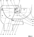
- FIG. 1 to 3 a schematic sectional view of a sanitary article arrangement 1 according to a preferred embodiment is shown.
- the sanitary article arrangement 1 comprises a sanitary article 2 with a receiving space 3 and a drain space 24 with a drain pipe 4.
- the drain space 24 connects to the receiving space 3 and the drain pipe 4 connects to the drain space 24.
- the drain pipe 4 is preferably an integral part of the sanitary item 2. Viewed in the installed position, the drain space 24 is below the receiving space 3.
- the transition between the drain space 24 and the receiving space 3 is preferably defined by the siphon line S described below.
- the sanitary article arrangement 1 comprises a tubular element 5 which is connected to the drain pipe 4 with a first end 6 .
- the sanitary article arrangement 1 comprises an actuating element 7 which is connected to the tubular element 5 and with which the Tubular element 5 can be moved from a siphon position into a discharge position and from the discharge position into the siphon position.
- the tubular element 5 is made of a soft material and is thus easily deformable when moving from the siphon position to the emptying position and back again.
- tubular element 5 is shown in the siphon position.
- tubular element 5 is shown in an intermediate position between the siphon position and the drain position.
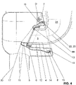
- tubular element 5 is shown in the emptying position.
- the sanitary article 2 is shown as a toilet bowl.
- the sanitary article 2 can also have a different design.
- the sanitary article 2 can also be designed as a urinal, a washbasin, a shower drain, etc.
- the tubular element 5 lies in such a way that a second end 8 of the tubular element 5 comes to lie at a level which is higher than the drain pipe 4 . This means that the second end 8 comes to lie above the drain pipe.
- the second end 8 is positioned in such a way that a siphon area 9 can be provided with the drain pipe 4 and the pipe element 5 in such a way that water in the drain pipe 4 and in the pipe element 5 can provide an odor trap.
- the siphon line S is shown. In the siphon position, the siphon area 9 is filled at least up to this line, so that an odor trap can be provided.
- the tubular element 5 For emptying, the tubular element 5 is moved with the actuating element 7 into the emptying position. During the movement from the siphon position into the emptying position, the tubular element 5 is moved with its second end 8 on the outside of the tubular element 5 in the direction of its first end 6 . This results in a rolling movement of the tubular element 5 towards the second end 8 .
- the actuating element is pivoted about the arrow P about an axis of rotation D.
- the pipe element 5 is moved backwards over itself in the direction of the discharge pipe 4 .
- the tubular element 5 is shown in an intermediate position between the siphon position and the drain position. With further advance movement, the tubular element 5 then reaches the emptying position according to FIG figure 4 .
- the siphon area can move in the emptying position 9 empty completely. After the emptying process, the tubular element 5 is moved from the emptying position back into the siphon position.
- the emptying process can be further supported by introducing flushing water into the receiving space 3 .
- rinsing water can be added to the receiving space 3 via a rinsing water inlet opening 21 in the sanitary article.
- the emptying process of the siphon is preferably clocked in such a way that it does not last more than a few seconds.
- the movement from the siphon position to the emptying position and back to the siphon position takes no more than 5 seconds.
- the siphon area 9 is refilled with water so that the odor trap is restored.
- the tubular element 5 is moved with its second end 8 on the outside toward the tubular element 5 over the tubular element 5 .
- the second end is moved towards the first end 6 and further over the first end 6 .
- the second end 8 comes to lie behind the first end 6, which is of the figure 4 is clearly visible.
- the tubular element 5 continuously slips over itself with its second end 8 during the movement from the siphon position into the emptying position.
- the inner side 16 of the tubular element 5 forms a discharge edge 17 .
- the lowest point of the discharge edge 17 is at the same level as or below the lowest point of the discharge pipe 4.
- the second end 8 of the tubular element 5 is designed as a free end and lies with an end face 10 in the siphon position, preferably in the horizontal.
- the second end 8 forms an overflow edge from the siphon area. If water continues to flow into the siphon area 9 viewed from the receiving space 3 , water flows out of the siphon area 9 via the second end 8 .
- the second end 8 is then pivoted in the direction of the first end 6 .
- the angle of the pivoting movement from the horizontal is greater than 90°. The angle is in a range from 90° to 110°.
- the axis of rotation about which the pivoting movement is carried out is transverse and spaced from a central axis M4 which extends through the drain pipe 4.
- the axis of rotation D is here at a small distance from a plane which is spanned by the second 8 of the tubular element 5 in the siphon position.
- the distance between the central axis M4 and the axis of rotation D is equal or substantially equal to the distance between the central axis M15 and the axis of rotation D.
- the axis of rotation D is collinear with a line of intersection of a first plane passing through the end face of the second End 8 is spanned and a second plane which is spanned by the face of the end of the drain pipe 4.
- the actuating element is preferably driven by an electrical or fluidic drive, which is not shown in the figures.
- the inner diameter of the tube element 5 increases from the first end 6 to the second end 8 .
- This increase in diameter has the advantage that the deformation of the tubular element, which occurs during the movement from the siphon position to the emptying position, can be provided in a material-friendly manner.
- the tubular element 5 surrounds the drain pipe 4 on the outside with its first end 6 .
- the pipe element 5 on the outside 12 of the drain pipe 4 is in a watertight connection with the outside 12 .
- the pipe element 5 also protrudes beyond an end face 13 of the discharge pipe 4 in the direction of its central axis M4.
- the minimum inner diameter of the tubular element 5 is in the area of the end face 13.
- the inner diameter of the tubular element 5 is preferably slightly larger than the inner diameter of the discharge pipe 4 in the area of the contact point with the tubular element 5.
- the inside 14 of the tubular element 5 is designed as a smooth surface without any further structural elevations.
- the actuating element 7 has a retaining ring 15 in the embodiment shown.
- the retaining ring 15 extends around a central axis M15, which runs at right angles to the axis of rotation D and at a distance from it.
- the second end 8 of the tubular element 5 is fastened to the retaining ring 15 .
- the tubular element 5 extends through the retaining ring 15 and is guided around the retaining ring 15 on the front side and on the outside. On the outside, the tubular element 5 engages with an elevation 22 a groove 23 on the retaining ring 15.
- the second end 8 is provided by the area of the tubular element 5 lying on the front side of the retaining ring 15 .
- a housing 18 is also connected to the drain pipe 4 .
- the housing 18 is arranged on the tubular element 5 in the region of the attachment point between the drain pipe 4 and the tubular element 5 .
- the housing 18 is connected to the drain pipe 4 in an odour-tight manner.
- the tubular element 5 and the actuating element 7 are placed in the interior space 19 of the housing 18 .
- the housing also has a drain opening 20 .
- the siphon area 9 empties into the outflow opening 20.
- Another pipe can be connected to the outflow opening 20.
- the outflow edge 17 preferably lies above the clear width of the outflow opening 20 of the housing 18 such that the contents of the siphon area are guided into the outflow opening 20 .
- the housing 18 is designed in such a way that, in the emptying position, space is created for accommodating the actuating element 7 and the pipe element 5, both of which lie above the drain pipe 4.
Landscapes
- Health & Medical Sciences (AREA)
- Life Sciences & Earth Sciences (AREA)
- Engineering & Computer Science (AREA)
- Hydrology & Water Resources (AREA)
- Public Health (AREA)
- Water Supply & Treatment (AREA)
- Sanitary Device For Flush Toilet (AREA)
- Sink And Installation For Waste Water (AREA)
Abstract
einen Sanitärartikel (2) mit einem Aufnahmeraum (3) und einem sich dem Aufnahmeraum (3) anschliessenden Abflussraum (24) mit einem Abflussrohr (4),
ein Rohrelement (5), das sich mit einem ersten Ende (6) dem Abflussrohr (4) anschliesst, und
ein mit dem Rohrelement (5) in Verbindung stehendes Betätigungselement (7), mit welchem das Rohrelement (5) von einer Siphonlage in eine Entleerungslage bewegbar ist,
wobei das Rohrelement (5) in der Siphonlage derart liegt, dass ein zweites Ende (8) des Rohrelements (5) auf einer Höhenlage zu liegen kommt, die höher als das Abflussrohr (4) liegt, so dass mit dem Abflussraum (24), dem Abflussrohr (4) und dem Rohrelement (5) ein Siphonbereich (9) bereitstellbar ist, derart, dass durch Wasser im Siphonbereich (9) ein Geruchsverschluss bereitstellbar ist, und
wobei zur Entleerung des Siphonbereichs (9) das Rohrelement (5) in die Entleerungslage bewegt wird, wobei bei der Bewegung von der Siphonlage in die Entleerungslage das Rohrelement (5) mit seinem zweiten Ende (8) aussenseitig zum Rohrelement (5) in Richtung dessen erstes Ende (6) bewegt wird.
Description
- Die vorliegende Erfindung betrifft eine Sanitärartikelanordnung nach Anspruch 1 sowie ein Verfahren zum Betrieb einer Sanitärartikelanordnung nach Anspruch 15.
- Aus der
EP 3 643 844 ist eine Toilette bekannt geworden, die einen flexiblen Siphon zeigt. Dabei weist der Siphon einen flexiblen Abschnitt in der Form eines Faltenbalges auf, welcher von einer Verschlusslage in eine Entleerungslage bewegbar ist. Bei der Bewegung von der Verschlusslage in die Entleerungslage wird ein Siphonbereich zusammen mit dem Faltenbalg um 90° verschwenkt, so dass der Inhalt der Toilettenschüssel und des Siphonbereichs gespült werden kann. - Nachteilig an der
EP 3 643 844 ist, dass die Verschwenkung von der Verschlusslage in der Entleerungslage sehr viel Raum einnimmt. Mit anderen Worten gesagt, ist der Hohlraum der Toilette, in welchem sich der Siphon befindet, vergleichsweise gross auszubilden, wodurch die Gesamtgrösse der Toilettenschüssel sehr viel Raum einnimmt. - Ein weiterer Nachteil ist die Verwendung des gezeigten Faltenbalges, welcher im Innenraum des flexiblem Elementes Rillen des Faltenbalgs aufweist. Die Rillen verhindern ein vollständiges Ausfliessen des gesamte Siphoninhaltes. Es verbleibt bei jedem Entleerungsvorgang das in den Rillen liegende Siphonwasser im Siphon.
- Ausgehend von diesem Stand der Technik liegt der vorliegenden Erfindung eine Aufgabe zugrunde, eine Sanitärartikelanordnung anzugeben, welche die Nachteile des Standes der Technik überwindet. Insbesondere soll eine Sanitärartikelanordnung angegeben werden, welche unter der Massgabe einer kompakten Struktur, eine wassersparende Entleerung des Siphons ermöglicht.
- Diese Aufgabe löst der Gegenstand von Anspruch 1. Demgemäss umfasst eine Sanitärartikelanordnung einen Sanitärartikel mit einem Aufnahmeraum und einem sich dem Aufnahmeraum anschliessenden Abflussraum mit einem Abflussrohr, ein Rohrelement, das sich mit einem ersten Ende dem Abflussrohr anschliesst, und ein mit dem Rohrelement in Verbindung stehendes Betätigungselement, mit welchem das Rohrelement von einer Siphonlage in eine Entleerungslage bewegbar ist. In der Siphonlage liegt das Rohrelement derart, dass ein zweites Ende des Rohrelements auf einer Höhenlage zu liegen kommt, die höher als das Abflussrohr liegt, so dass mit dem Abflussraum, dem Abflussrohr und dem Rohrelement ein Siphonbereich bereitstellbar ist, derart, dass durch Wasser im Siphonbereich ein Geruchsverschluss bereitstellbar ist. Zur Entleerung des Siphonbereichs wird das Rohrelement in die Entleerungslage bewegt, wobei bei der Bewegung von der Siphonlage in die Entleerungslage das Rohrelement mit seinem zweiten Ende aussenseitig, das heisst auf der Aussenseite, zum Rohrelement in Richtung dessen erstes Ende bewegt wird.
- Durch die Bewegung des zweiten Endes über die Aussenseite des Rohrelements ersten Ende hin wird erreicht, dass das Rohrelement bei der Bewegung bezüglich seiner Grösse kompakter wird. Das heisst, der benötigte Raumbedarf für die Bewegung von der Siphonlage in die Entleerungslage muss nicht vergrössert werden.
- Mit anderen Worten gesagt wird bei der Bewegung aus der Siphonlage in die Entleerungslage das Rohrelement über sich selber gestülpt bzw. aussenseitig über sich selber gerollt. Das Rohrelement kann auch als Rollbalg bezeichnet werden. Das Rohrelement ist aus einem flexiblen Material bereitgestellt und kann daher auch als flexibles Rohrelement bezeichnet werden.
- Vorzugsweise wird das Rohrelement derart bewegt, dass sich der Siphonbereich durch die Bewegung des Rohrelements vollständig entleeren kann.
- In der Siphonlage weist das Rohrelement die Form eines Rohrbogens auf, der sich dem Abflussrohr anschliesst und in Einbaulage nach oben hin erstreckt.
- Vorzugsweise ist der Sanitärartikel eine Toilettenschüssel oder ein Urinal. In diesem Fall wird das Rohrelement bei jedem Spülvorgang in die Entleerungslage gebracht.
- Es ist aber auch denkbar, dass der Sanitärartikel ein Waschbecken oder ein Duschelement, wie eine Duschwanne oder eine Badewanne ist. Hier kann das Rohrelement bei einem Reinigungsvorgang in die Entleerungslage gebracht werden, wobei dann Rückstände im Siphon sehr einfach in die Abflussleitung gespült werden können.
- Vorzugsweise liegt das Rohrelement so, dass bei dessen Verformung die Bewegung entlang der neutralen Faser erfolgt, was für die Materialbelastung ein Vorteil ist, da weniger Querkräfte auftreten.
- Vorzugsweise erstreckt sich das Abflussrohr vom Aufnahmeraum her gesehen nach unten und verläuft dann in Einbaulage im Wesentlichen in der Horizontalen.
- Das Rohrelement steht mit seinem ersten Ende fest mit dem Abflussrohr in Verbindung. Bei der Bewegung des Rohelements von der Siphonlage in die Entleerungslage verbleibt das erste Ende in seiner festen Position.
- Nach Erreichen der Entleerungslage kann das Rohrelement von der Entleerungslage wieder in die Siphonlage zurück bewegt werden.
- Vorzugsweise wird das Rohrelement mit seinem zweiten Ende bei der Bewegung in die Entleerungslage aussenseitig zum ersten Ende über das erste Ende hinweg bewegt und kommt bei Erreichen der Entleerungslage ausgehend von der Siphonlage hinter das erste Ende zu liegen.
- Hierdurch wird sichergestellt, dass sich in der Entleerungslage der Siphonbereich vollständig entleeren kann.
- Mit anderen Worten gesagt, wird das Rohrelement über das Abflussrohr gezogen.
- Vorzugsweise überstülpt das Rohrelement bei der Bewegung von der Siphonlage in die Entleerungslage sich mit seinem zweiten Ende kontinuierlich selbst.
- Vorzugsweise definiert das zweite Ende ein freies Rohrende und liegt in der Siphonlage mit seiner Stirnfläche vorzugsweise in der Horizontalen liegt. Das heisst in einer Ebene rechtwinklig zur Lotrichtung.
- Die Stirnfläche des zweiten Endes liegt in der Siphonlage auf einer Höhenlage die höher ist als die des Abflussrohrs.
- Vorzugsweise vergrössert sich der Innendurchmesser des Rohrelements vom ersten Ende zum zweiten Ende hin.
- Durch die Vergrösserung des Innendurchmessers ergeht der Vorteil, dass die Bewegung von der Siphonlage in die Entleerungslage, insbesondere der Vorgang des Umstülpens des Rohrelementes, mit geringem Kraftaufwand möglich ist. Weiter kann eine materialschonende Verformung des Rohrelements erreicht werden. Im Zusammenhang mit der materialschonenden Verformung kann gesagt werden, dass je grösser die Durchmesserveränderungen zwischen dem ersten Ende und dem zweiten Ende ist, desto materialschonender ist dies für das Rohrelement.
- Vorzugsweise umgibt das Rohrelement das Abflussrohr aussenseitig und steht auf der Aussenseite des Abflussrohrs mit dem Rohrelement in wasserdichter Verbindung.
- Vorzugsweise erstreckt sich das Rohrelement von der Aussenseite des Abflussrohrs über die Stirnfläche des Abflussrohr nach innen. Hierdurch wird eine gute Anbindung des Rohrelements an das Abflussrohr erreicht.
- Vorzugsweise liegt die Stirnseite des Abflussrohrs in einer Schnittebene, welche in einem Winkel winklig geneigt zur Mittelachse des Abflussrohrs liegt. Der Winkel kann zwischen 45° und 135° sein.
- Vorzugsweise weist das Rohrelement im Anschlussbereich an das Abflussrohr einen Innendurchmesser auf, der grösser ist als der Innendurchmesser des Abflussrohrs. Hierdurch kann ein Verstopfen oder eine mangelhafte Entleerung ausgeschlossen werden.
- Vorzugsweise ist das Rohrelement aus einem Kunststoff, insbesondere aus einem Elastomer, wie EPDM (Ethylen-Propylen-Dien-Kautschuk). Alternativerweise sind auch andere Elastomere oder andere Werkstoffe, wie Silikon oder thermoplastische Elastomere einsetzbar.
- Vorzugsweise weist das Rohrelement eine Shore-Härte im Bereich von 50 bis 70, insbesondere von 55 bis 65, auf.
- Vorzugsweise ist die Wandstärke des Rohrelements zwischen 0.25 und 2.5 Millimetern, insbesondere zwischen 1 und 2 Millimetern.
- Vorzugsweise wird bei dickeren Wandstärken eine kleiner Shore-Härte gewählt als bei dünneren Wandstärken.
- Vorzugsweise ist die Innenseite des Rohrelements als glatte Fläche ausgebildet. Hierdurch wird erreicht, dass sich der Siphonbereich vollständig entleert.
- Vorzugsweise ist das Betätigungselement um eine Drehachse verschwenkbar, wobei die Drehachse quer und beabstandet zur Mittelachse vom Abflusssrohr steht.
- Vorzugsweise wird das Betätigungselement mit einem elektrischen oder fluidischen Antrieb betätigt.
- Vorzugsweise weist das Betätigungselement einen Haltering auf, an welchem das zweite Ende befestigt ist, wobei sich der Haltering vorzugsweise vollständig um das zweite Ende herum erstreckt.
- Vorzugsweise erstreckt sich die Drehachse quer zur Mittelachse des Halterings und liegt beabstandet zur Mittelachse des Halterings.
- Der Haltering kann aussenseitig zum Rohrelement liegen. Dabei steht die Aussenseite des Rohrelements in Kontakt mit einer Ringfläche des Halterings. In einer anderen Variante kann des Rohrelement den Haltering auch mindestens teilweise umgeben. Vom ersten her gesehen wird dabei das Rohrelement durch den Haltering hindurch geführt und dann auf der Aussenseite des Halterings zurückgeführt. Das zweite Ende wird in diesem Fall durch den Teil des Rohrelements bereitgestellt, welches auf einer Stirnfläche des Halterings liegt.
- Der Innendurchmesser des Halterings ist grösser als der Aussendurchmesser des Abflussrohrs.
- Bei der Bewegung von der Siphonlage in die Entleerungslage wird der Haltering über das Rohrende des Abflussrohrs geführt und kommt in der Entleerungslage hinter das Rohrende des Abflussrohrs bzw. hinter die Stelle, an welcher das Rohrelement zum Abflussrohr befestigt ist, zu liegen. Mit anderen Worten gesagt, wird das zweite Rohrende und der Haltering über das Abflussrohr gestülpt.
- Vorzugsweise bildet in der Entleerungslage die Innenseite des Rohrelements eine Abflusskante, wobei in der Entleerungslage der tiefste Punkt der Abflusskante auf gleicher Höhe oder unterhalb des tiefsten Punkts des Abflussrohrs liegt.
- Mit anderen Worten gesagt liegt der tiefste Punkt der Abflusskante in der Entleerungslage unterhalb oder auf Höhe des Siphongrunds.
- Vorzugsweise schliesst sich dem Abflussrohr ein Gehäuse an, welches aussenseitig geruchsdicht mit Abflussrohr in Verbindung steht, wobei das Rohrelement und das Betätigungselement im Innenraum des Gehäuses angeordnet sind und wobei das Gehäuse eine Ablauföffnung aufweist.
- An die Ablauföffnung kann ein Ablaufrohr angeschlossen werden,
- Vorzugsweise liegt die Abflusskante in der Entleerungslage über der lichten Weite der Ablauföffnung des Gehäuses, derart, dass der wegzuspülende Inhalt des Siphonbereichs in die Ablauföffnung fliessen kann. Die Abflusskante kann aber auch versetzt zur Ablauföffnung liegen, wobei das wegzuführende Spülwasser dann über die Innenwand des Gehäuses zur Ablauföffnung geführt wird.
- Ein Verfahren zum Betrieb einer Sanitärartikelanordnung nach obiger Beschreibung ist dadurch charakterisiert, dass bei Einleiten eines Entleerungsvorgangs das Rohrelement von der Siphonlage in die Entleerungslage bewegt wird und dass nach erfolgter Entleerung das Rohrelement von der Entleerungslage in die Siphonlage bewegt wird, wobei der wieder bereitgestellte Siphonbereich mit Wasser befüllt wird.
- Besonders bevorzugt wird vor und/oder während der Bewegung des Rohrelements von der Siphonlage in die Entleerungslage Spülwasser in den Aufnahmeraum eingebracht, so dass die Entleerung des Siphonbereichs mit eindringendem Spülwasser unterstützt werden kann.
- Ganz besonders bevorzugt wird während der gesamten Bewegung von der Siphonlage in die Entleerungslage und dann von der Entleerungslage in die Siphonlage zurück kontinuierlich Spülwasser in das Abflussrohr geführt.
- Weitere Ausführungsformen sind in den abhängigen Ansprüchen angegeben.
- Bevorzugte Ausführungsformen der Erfindung werden im Folgenden anhand der Zeichnungen beschrieben, die lediglich zur Erläuterung dienen und nicht einschränkend auszulegen sind. In den Zeichnungen zeigen:
- Fig. 1
- eine Schnittdarstellung einer Sanitärartikelanordnung nach einer Ausführungsform gemäss der vorliegenden Erfindung;
- Fig. 2
- eine Detailansicht der
Figur 1 , wobei ein Rohrelement in der Siphonlage ist; - Fig. 3
- die Detailansicht der
Figur 2 , wobei das Rohrelement sich der Siphonlage und einer Entleerungslage sich befindet; und - Fig. 4
- die Detailansicht der
Figur 2 , wobei das Rohrelement sich in der Entleerungslage befindet. - In den
Figuren 1 bis 3 wird eine schematische Schnittansicht einer Sanitärartikelanordnung 1 gemäss einer bevorzugten Ausführungsform gezeigt. - Die Sanitärartikelanordnung 1 umfasst einen Sanitärartikel 2 mit einem Aufnahmeraum 3 und einem Abflussraum 24 mit einem Abflussrohr 4. Der Abflussraum 24 schliesst sich dem Aufnahmeraum 3 an und das Abflussrohr 4 schliesst sich dem Abflussraum 24 an. Das Abflussrohr 4 ist vorzugsweise integraler Bestandteil vom Sanitärartikel 2. In Einbaulage gesehen liegt der Abflussraum 24 unterhalb des Aufnahmeraums 3. Der Übergang zwischen Abflussraum 24 und Aufnahmeraum 3 wird vorzugsweise durch die unten beschrieben Siphonlinie S definiert.
- Weiter umfasst die Sanitärartikelanordnung 1 ein Rohrelement 5, das sich mit einem ersten Ende 6 dem Abflussrohr 4 anschliesst. Zudem umfasst die Sanitärartikelanordnung 1 ein mit dem Rohrelement 5 in Verbindung stehendes Betätigungselement 7, mit welchem das Rohrelement 5 von einer Siphonlage in eine Entleerungslage sowie von der Entleerungslage in die Siphonlage bewegbar ist. Das Rohrelement 5 ist aus einem weichen Material und somit bei der Bewegung von der Siphonlage in die Entleerungslage und wieder zurück leicht verformbar.
- In der
Figur 1 wird das Rohrelement 5 in der Siphonlage gezeigt. In derFigur 2 wird das Rohrelement 5 in einer Zwischenlage zwischen der Siphonlage und der Entleerungslage gezeigt. In derFigur 3 wird das Rohrelement 5 in der Entleerungslage gezeigt. - In der gezeigten Ausführungsform wird der Sanitärartikel 2 als Toilettenschüssel gezeigt. Der Sanitärartikel 2 kann aber auch eine andere Ausbildung haben. Beispielsweise kann der Sanitärartikel 2 auch als Urinal, als Waschbecken, als Duschenablauf, etc. ausgebildet sein.
- In der Siphonlage liegt das Rohrelement 5 derart, dass ein zweites Ende 8 des Rohrelements 5 auf einer Höhenlage zu liegen kommt, die höher als das Abflussrohr 4 liegt. Das heisst, dass das zweiten Ende 8 oberhalb des Abflussrohrs zu liegen kommt. Das zweite Ende 8 liegt dabei so, dass mit dem Abflussrohr 4 und dem Rohrelement 5 ein Siphonbereich 9 bereitstellbar ist, derart, dass durch Wasser im Abflussrohr 4 und im Rohrelement 5 ein Geruchsverschluss bereitstellbar ist.
- In der
Figur 1 wird die Siphonlinie S dargestellt. In der Siphonlage wird der Siphonbereich 9 mindestens bis zu dieser Linie befüllt, so dass ein Geruchsverschluss bereitstellbar ist. - Für die Entleerung wird das Rohrelement 5 mit dem Betätigungselement 7 in die Entleerungslage bewegt. Bei der Bewegung von der Siphonlage in die Entleerungslage wird das Rohrelement 5 mit seinem zweiten Ende 8 aussenseitig zum Rohrelement 5 in Richtung dessen erstes Ende 6 bewegt wird. Es kommt dabei zu einer Rollbewegung des Rohrelements 5 zum zweiten Ende 8 hin.
- Ausgehend von der Siphonlage gemäss
Figuren 1 und2 wird das Betätigungselement um den Pfeil P um eine Drehachse D verschwenkt. Dabei wird das Rohrelement 5 über sich selber nach hinten hin in Richtung Abflussrohr 4 bewegt. In derFigur 3 wird das Rohrelement 5 in einer Zwischenlage zwischen der Siphonlage und der Entleerungslage gezeigt. Bei weiterem Bewegungsvorschub erreicht das Rohrelement 5 sodann die Entleerungslage gemäss derFigur 4 . In der Entleerungslage kann sich der Siphonbereich 9 vollständig entleeren. Nach dem Entleerungsvorgang wird das Rohrelement 5 von der Entleerungslage wieder in die Siphonlage bewegt. - Der Entleerungsvorgang kann über das Einbringen von Spülwasser in den Aufnahmeraum 3 weiter unterstützt werden. Beispielsweise kann Spülwasser über eine Spülwassereintrittsöffnung 21 im Sanitärartikel in den Aufnahmeraum 3 gegeben werden.
- Der Entleerungsvorgang des Siphons ist vorzugsweise derart getaktet, dass dieser nicht mehr als wenige Sekunden dauert. Vorzugsweise dauert die Bewegung von der Siphonlage in die Entleerungslage und retour in die Siphonlage nicht mehr als 5 Sekunden. Weiter wird nach dem Entleerungsvorgang der Siphonbereich 9 wieder mit Wasser aufgefüllt, so dass der Geruchsverschluss wieder hergestellt ist.
- Bei der Bewegung von der der Siphonlage in die Entleerungslage wird das Rohrelement 5 mit seinem zweiten Ende 8 aussenseitig zum Rohrelement 5 über das Rohrelement 5 bewegt. Dabei wird das zweite Ende zum ersten Ende 6 hin und weiter über das erste Ende 6 hinweg bewegt wird. Bei Erreichen der Entleerungslage ausgehend von der Siphonlage kommt das zweite Ende 8 hinter das erste Ende 6 zu liegen, was von der
Figur 4 gut ersichtlich ist. Wie von denFiguren 2 bis 4 gezeigt wird, überstülpt sich das Rohrelement 5 bei der Bewegung von der Siphonlage in die Entleerungslage mit seinem zweiten Ende 8 kontinuierlich. - In der Entleerungslage gemäss der
Figur 4 bildet die Innenseite 16 des Rohrelements 5 eine Abflusskante 17 bildet. Der tiefste Punkt der Abflusskante 17 liegt auf gleicher Höhe oder unterhalb des tiefsten Punkts des Abflussrohrs 4. - Das zweite Ende 8 des Rohrelements 5 ist als freies Ende ausgebildet und liegt mit einer Stirnfläche 10 in der Siphonlage vorzugsweise in der Horizontalen. Dabei bilde das zweite Ende 8 eine Überlaufkante aus dem Siphonbereiche. Sofern vom Aufnahmeraum 3 her gesehen Wasser in den Siphonbereich 9 nachfliesst, fliesst Wasser aus den Siphonbereich 9 über das zweite Ende 8 ab. Ausgehend von dieser Horizontallage wird das zweite Ende 8 dann in Richtung erstes Ende 6 verschwenkt. In der gezeigten Ausführungsform ist der Winkel der Verschwenkbewegung aus der Horizontalen grösser als 90°. Der Winkel liegt in einem Bereich von 90° bis 110°.
- Die Drehachse, um welche die Verschwenkbewegung ausgeführt wird, steht quer und beabstandet zu einer Mittelachse M4, welche sich durch das Abflussrohr 4 erstreckt. Die Drehachse D liegt hier in einem geringen Abstand zu einer Ebene, welche durch das zweite 8 des Rohrelements 5 in der Siphonlage aufgespannt wird. Vorzugsweise ist der Abstand zwischen der Mittelachse M4 und der Drehachse D gleich bzw. im Wesentlichen gleich zum Abstand zwischen der Mittelachse M15 und der Drehachse D. Vorzugsweise liegt die Drehachse D kollinear zur einer Schnittlinie, von einer ersten Ebene, die durch die Stirnfläche des zweiten Endes 8 aufgespannt wird und von einer zweiten Ebene, die durch die Stirnfläche des Endes des Abflussrohrs 4 aufgespannt ist.
- Das Betätigungselement wird vorzugsweise durch einen elektrischen oder fluidischen Antrieb, der in den Figuren nicht dargestellt ist, angetrieben.
- Von den
Figuren 1 und2 wird ersichtlich, dass sich der Innendurchmesser des Rohrelements 5 vom ersten Ende 6 zum zweiten Ende 8 hin vergössert. Diese Durchmesservergrösserung hat den Vorteil, dass die Verformung des Rohrelements, welche bei der Bewegung von der Siphonlage in die Entleerungslage entsteht, materialschonender bereitstellbar ist. - In der gezeigten Ausführungsform umgibt das Rohrelement 5 mit seinem ersten Ende 6 das Abflussrohr 4 aussenseitig. Dabei steht das Rohrelement 5 auf der Aussenseite 12 des Abflussrohr 4 mit der Aussenseite 12 in einer wasserdichten Verbindung. Weiter ragt das Rohrelement 5 von der Aussenseite 12 gesehen über eine Stirnfläche 13 des Abflussrohrs 4 in Richtung dessen Mittelachse M4. Der minimale Innendurchmesser des Rohrelements 5 liegt im Bereich der Stirnfläche 13. Vorzugsweise ist der Innendurchmesser des Rohrelements 5 leicht grösser als der Innendurchmesser des Abflussrohrs 4 im Bereich der Kontaktstelle mit dem Rohrelement 5.
- In der gezeigten Ausführungsform ist die Innenseite 14 des Rohrelements 5 als glatte Fläche ohne weitere Strukturerhebungen ausgebildet.
- Das Betätigungselement 7 weist in der gezeigten Ausführungsform einen Haltering 15 auf. Der Haltering 15 erstreckt sich dabei um eine Mittelachse M15, welche rechwinklig und beabstandet zur Drehachse D verläuft. Am Haltering 15 ist das zweite Ende 8 des Rohrelements 5 befestigt. In der gezeigten Ausführungsform erstreckt sich das Rohrelement 5 durch den Haltering 15 hindurch und wird frontseitig und aussenseitig um den Haltering 15 geführt. Aussenseitig greift das Rohrelement 5 mit einer Erhebung 22 in eine Nut 23 am Haltering 15 ein. Das zweite Ende 8 wird dabei durch den an der Frontseite des Halterings 15 liegenden Bereich des Rohrelements 5 bereitgestellt.
- Weiter schliesst sich dem Abflussrohr 4 ein Gehäuse 18 an. Das Gehäuse 18 ist hier im Bereich der Befestigungsstelle zwischen dem Abflussrohr 4 und dem Rohrelement 5 am Rohrelement 5 angeordnet. Das Gehäuse 18 steht dabei geruchsdicht mit dem Abflussrohr 4 in Verbindung. Das Rohrelement 5 und das Betätigungselement 7 sind dabei im Innenraum 19 des Gehäuses 18 platziert. Weiter weist das Gehäuse eine Ablauföffnung 20 auf. Beim Entleerungsvorgang entleert sich der Siphonbereich 9 in die Ablauföffnung 20. An der Ablauföffnung 20 ist ein weiteres Rohr anschliessbar. Vorzugsweise liegt die Abflusskante 17 in der Entleerungslage über der lichten Weite der Ablauföffnung 20 des Gehäuses 18, derart, dass sich der Inhalt des Siphonbereichs in die Ablauföffnung 20 geführt wird. Das Gehäuse 18 ist derart ausgebildet, dass in der Entleerungslage Raum für die Aufnahme vom Betätigungselement 7 und dem Rohrelement 5, welche beide über dem Abflussrohr 4 liegen, geschaffen wird.
-
- 1
- Sanitärartikelanordnung
- 2
- Sanitärartikel
- 3
- Aufnahmeraum
- 4
- Abflussrohr
- 5
- Rohrelement
- 6
- erstes Ende
- 7
- Betätigungselement
- 8
- zweites Ende
- 9
- Siphonbereich
- 10
- Stirnfläche
- 11
- Aussenseite vom Rohrelement
- 12
- Aussenseite vom Abflussrohr
- 13
- Stirnfläche
- 14
- Innenseite
- 15
- Haltering
- 16
- Innenseite
- 17
- Abflusskante
- 18
- Gehäuse
- 19
- Innenraum
- 20
- Ablauföffnung
- 21
- Spülwassereintrittsöffnung
- 22
- Erhebung
- 23
- Nut
- 24
- Abflussraum
- M4
- Mittelachse Abflussrohr 4
- D
- Drehachse
- M15
- Mittelachse Haltering
- S
- Siphonlinie
- P
- Pfeil
Claims (15)
- Sanitärartikelanordnung (1) umfassend
einen Sanitärartikel (2) mit einem Aufnahmeraum (3) und einem sich dem Aufnahmeraum (3) anschliessenden Abflussraum (24) mit einem Abflussrohr (4),
ein Rohrelement (5), das sich mit einem ersten Ende (6) dem Abflussrohr (4) anschliesst, und
ein mit dem Rohrelement (5) in Verbindung stehendes Betätigungselement (7), mit welchem das Rohrelement (5) von einer Siphonlage in eine Entleerungslage bewegbar ist,
wobei das Rohrelement (5) in der Siphonlage derart liegt, dass ein zweites Ende (8) des Rohrelements (5) auf einer Höhenlage zu liegen kommt, die höher als das Abflussrohr (4) liegt, so dass mit dem Abflussraum (24), dem Abflussrohr (4) und dem Rohrelement (5) ein Siphonbereich (9) bereitstellbar ist, derart, dass durch Wasser im Siphonbereich (9) ein Geruchsverschluss bereitstellbar ist,
dadurch gekennzeichnet,
dass zur Entleerung des Siphonbereichs (9) das Rohrelement (5) in die Entleerungslage bewegt wird, wobei bei der Bewegung von der Siphonlage in die Entleerungslage das Rohrelement (5) mit seinem zweiten Ende (8) aussenseitig zum Rohrelement (5) in Richtung dessen erstes Ende (6) bewegt wird. - Sanitärartikelanordnung (1) nach Anspruch 1, dadurch gekennzeichnet, dass das Rohrelement (5) mit seinem zweiten Ende (8) bei der Bewegung in die Entleerungslage aussenseitig zum ersten Ende (6) über das erste Ende (6) hinweg bewegt wird und bei Erreichen der Entleerungslage ausgehend von der Siphonlage hinter das erste Ende (6) zu liegen kommt.
- Sanitärartikelanordnung (1) nach Anspruch 1 oder 2, dadurch gekennzeichnet, dass das Rohrelement (5) bei der Bewegung von der Siphonlage in die Entleerungslage sich mit seinem zweiten Ende (8) kontinuierlich selbst überstülpt.
- Sanitärartikelanordnung (1) nach einem der vorhergehenden Ansprüche, dadurch gekennzeichnet, dass das zweite Ende (8) ein freies Rohrende definiert und in der Siphonlage mit seiner Stirnfläche (10) vorzugsweise in der Horizontalen liegt.
- Sanitärartikelanordnung (1) nach einem der vorhergehenden Ansprüche, dadurch gekennzeichnet, dass sich der Innendurchmesser des Rohrelements (5) vom ersten Ende (6) zum zweiten Ende (8) hin vergrössert.
- Sanitärartikelanordnung (1) nach einem der vorhergehenden Ansprüche, dadurch gekennzeichnet, dass das Rohrelement (5) das Abflussrohr (4) aussenseitig umgibt und auf der Aussenseite (12) des Abflussrohrs (4) mit dem Rohrelement (5) in wasserdichter Verbindung steht.
- Sanitärartikelanordnung (1) nach einem der vorhergehenden Ansprüche, dadurch gekennzeichnet, dass das Rohrelement (5) sich von der Aussenseite (12) des Abflussrohrs (4) über die Stirnfläche (13) des Abflussrohrs (4) nach innen erstreckt.
- Sanitärartikelanordnung (1) nach einem der vorhergehenden Ansprüche, dadurch gekennzeichnet, dass das Rohrelement (5) im Anschlussbereich an das Abflussrohr (4) einen Innendurchmesser aufweist, der grösser ist als der Innendurchmesser des Abflussrohrs (4).
- Sanitärartikelanordnung (1) nach einem der vorhergehenden Ansprüche, dadurch gekennzeichnet,
dass das Rohrelement (5) aus einem Kunststoff, insbesondere aus einem Elastomer oder Silikon oder einem thermoplastischen Elastomer ist; und/oder
dass das Rohrelement (5) eine Shore-Härte im Bereich von 50 bis 70, insbesondere von 55 bis 65, aufweist; und/oder
dass die Innenseite (14) des Rohrelements (5) als glatte Fläche ausgebildet ist. - Sanitärartikelanordnung (1) nach einem der vorhergehenden Ansprüche, dadurch gekennzeichnet, dass das Betätigungselement (7) um eine Drehachse (D) verschwenkbar ist, wobei die Drehachse (D) quer und beabstandet zur Mittelachse (M4) vom Abflusssrohr (4) steht; und/oder dass das Betätigungselement (7) mit einem elektrischen oder fluidischen Antrieb betätigt wird.
- Sanitärartikelanordnung (1) nach einem der vorhergehenden Ansprüche, dadurch gekennzeichnet, dass das Betätigungselement (7) einen Haltering (15) aufweist, an welchem das zweite Ende (8) befestigt ist, wobei sich der Haltering (15) vorzugsweise vollständig um das zweite Ende (8) herum erstreckt.
- Sanitärartikelanordnung (1) nach einem der vorhergehenden Ansprüche, dadurch gekennzeichnet, dass in der Entleerungslage die Innenseite (16) des Rohrelements (5) eine Abflusskante (17) bildet, wobei in der Entleerungslage der tiefste Punkt der Abflusskante (17) auf gleicher Höhe oder unterhalb des tiefsten Punkts des Abflussrohrs (4) liegt.
- Sanitärartikelanordnung (1) nach einem der vorhergehenden Ansprüche, dadurch gekennzeichnet, dass sich dem Abflussrohr (4) ein Gehäuse (18) anschliesst, welches aussenseitig geruchsdicht mit Abflussrohr (4) in Verbindung steht, wobei das Rohrelement (5) und das Betätigungselement (7) im Innenraum (19) des Gehäuses (18) angeordnet sind und wobei das Gehäuse (18) eine Ablauföffnung (20) aufweist.
- Sanitärartikelanordnung (1) nach Anspruch 12 oder 13, dadurch gekennzeichnet, dass die Abflusskante (17) in der Entleerungslage über der lichten Weite der Ablauföffnung (20) des Gehäuses (18) liegt, derart, dass der wegzuspülende Inhalt des Siphonbereichs (9) in die Ablauföffnung (20) fliessen kann.
- Verfahren zum Betrieb einer Sanitärartikelanordnung (1) nach einem der vorhergehenden Ansprüche, dadurch gekennzeichnet, dass bei Einleiten eines Entleerungsvorgangs das Rohrelement (5) von der Siphonlage in die Entleerungslage bewegt wird und dass nach erfolgter Entleerung das Rohrelement (5) von der Entleerungslage in die Siphonlage bewegt wird, wobei der wieder bereitgestellte Siphonbereich mit Wasser befüllt wird.
Priority Applications (2)
| Application Number | Priority Date | Filing Date | Title |
|---|---|---|---|
| ES21162019T ES3043634T3 (en) | 2021-03-11 | 2021-03-11 | Sanitary ware assembly |
| EP21162019.0A EP4056776B1 (de) | 2021-03-11 | 2021-03-11 | Sanitärartikelanordnung |
Applications Claiming Priority (1)
| Application Number | Priority Date | Filing Date | Title |
|---|---|---|---|
| EP21162019.0A EP4056776B1 (de) | 2021-03-11 | 2021-03-11 | Sanitärartikelanordnung |
Publications (2)
| Publication Number | Publication Date |
|---|---|
| EP4056776A1 true EP4056776A1 (de) | 2022-09-14 |
| EP4056776B1 EP4056776B1 (de) | 2025-08-20 |
Family
ID=74871238
Family Applications (1)
| Application Number | Title | Priority Date | Filing Date |
|---|---|---|---|
| EP21162019.0A Active EP4056776B1 (de) | 2021-03-11 | 2021-03-11 | Sanitärartikelanordnung |
Country Status (2)
| Country | Link |
|---|---|
| EP (1) | EP4056776B1 (de) |
| ES (1) | ES3043634T3 (de) |
Citations (3)
| Publication number | Priority date | Publication date | Assignee | Title |
|---|---|---|---|---|
| US5657495A (en) * | 1993-01-27 | 1997-08-19 | Dufresne; Guy | trap-forming device and toilet bowl provided with such a device |
| CN101210438A (zh) * | 2006-12-29 | 2008-07-02 | 李永镐 | 座便器的排污装置 |
| EP3643844A1 (de) | 2017-06-20 | 2020-04-29 | Wawa Co., Ltd. | Abwasserableitungsvorrichtung einer toilette mit veränderlicher wassereinsparung |
-
2021
- 2021-03-11 EP EP21162019.0A patent/EP4056776B1/de active Active
- 2021-03-11 ES ES21162019T patent/ES3043634T3/es active Active
Patent Citations (3)
| Publication number | Priority date | Publication date | Assignee | Title |
|---|---|---|---|---|
| US5657495A (en) * | 1993-01-27 | 1997-08-19 | Dufresne; Guy | trap-forming device and toilet bowl provided with such a device |
| CN101210438A (zh) * | 2006-12-29 | 2008-07-02 | 李永镐 | 座便器的排污装置 |
| EP3643844A1 (de) | 2017-06-20 | 2020-04-29 | Wawa Co., Ltd. | Abwasserableitungsvorrichtung einer toilette mit veränderlicher wassereinsparung |
Also Published As
| Publication number | Publication date |
|---|---|
| EP4056776B1 (de) | 2025-08-20 |
| ES3043634T3 (en) | 2025-11-25 |
Similar Documents
| Publication | Publication Date | Title |
|---|---|---|
| WO2015024965A1 (de) | Geruchsverschlussvorrichtung | |
| EP2865817B1 (de) | Ablaufgarnitur für einen Spülkasten | |
| EP0467827B1 (de) | Ablaufanschluss an einem Sanitärartikel | |
| WO2019034311A1 (de) | Wc mit spülwasseranschluss | |
| EP4126628B1 (de) | Vakuumtoilette und behälterkörper für eine vakuumtoilette | |
| EP4499930B1 (de) | Spülkasten, insbesondere unterputzspülkasten, für ein wc oder urinal | |
| EP4056776B1 (de) | Sanitärartikelanordnung | |
| EP3825480A1 (de) | Spülwasserverteiler | |
| DE69409792T2 (de) | Geruchverschlussbildende vorrichtung und spülklosettbecken versehen mit einer derartigen vorrichtung | |
| EP3260607B1 (de) | Siphon | |
| DE102023123249A1 (de) | Anordnungssystem zur Anordnung eines Spülbehälters eines Sanitärausstattungsgegenstandes | |
| EP1832689A1 (de) | Unterdruckabwassereinrichtung | |
| DE20312629U1 (de) | Sanitäre Wasch- oder Spültischgarnitur | |
| EP3825479A1 (de) | Spülwasserverteiler | |
| EP3708724B1 (de) | Sanitärer ablauf mit überlaufschutz | |
| DE102018133514A1 (de) | WC-Anschlussvorrichtung zum wandseitigen Anschluss eines Dusch-WC und Verfahren zur Installation eines Dusch-WC unter Verwendung einer WC-Anschlussvorrichtung | |
| EP3783158B1 (de) | Ab- und überlaufarmatur für eine badewanne | |
| WO2001025554A1 (de) | Toilettenschüssel | |
| EP1175534B1 (de) | Wassersparende toilettenanlage | |
| EP4095323B1 (de) | Spülsystem | |
| EP0916775B1 (de) | Kastenkörper für einen Spülkasten | |
| DE102022115136B4 (de) | Vorrichtung zum Ablassen eines fluiden Mediums aus einem Behälter | |
| EP4095327B1 (de) | Spülventil | |
| EP1614816B1 (de) | Überlauf- und Ablaufgarnitur für sanitäre Apparate | |
| EP3647504A1 (de) | Sanitärartikelanordnung |
Legal Events
| Date | Code | Title | Description |
|---|---|---|---|
| PUAI | Public reference made under article 153(3) epc to a published international application that has entered the european phase |
Free format text: ORIGINAL CODE: 0009012 |
|
| STAA | Information on the status of an ep patent application or granted ep patent |
Free format text: STATUS: THE APPLICATION HAS BEEN PUBLISHED |
|
| AK | Designated contracting states |
Kind code of ref document: A1 Designated state(s): AL AT BE BG CH CY CZ DE DK EE ES FI FR GB GR HR HU IE IS IT LI LT LU LV MC MK MT NL NO PL PT RO RS SE SI SK SM TR |
|
| STAA | Information on the status of an ep patent application or granted ep patent |
Free format text: STATUS: REQUEST FOR EXAMINATION WAS MADE |
|
| 17P | Request for examination filed |
Effective date: 20230116 |
|
| RBV | Designated contracting states (corrected) |
Designated state(s): AL AT BE BG CH CY CZ DE DK EE ES FI FR GB GR HR HU IE IS IT LI LT LU LV MC MK MT NL NO PL PT RO RS SE SI SK SM TR |
|
| RAP1 | Party data changed (applicant data changed or rights of an application transferred) |
Owner name: GEBERIT INTERNATIONAL AG |
|
| GRAP | Despatch of communication of intention to grant a patent |
Free format text: ORIGINAL CODE: EPIDOSNIGR1 |
|
| STAA | Information on the status of an ep patent application or granted ep patent |
Free format text: STATUS: GRANT OF PATENT IS INTENDED |
|
| INTG | Intention to grant announced |
Effective date: 20250402 |
|
| P01 | Opt-out of the competence of the unified patent court (upc) registered |
Free format text: CASE NUMBER: APP_24934/2025 Effective date: 20250527 |
|
| GRAS | Grant fee paid |
Free format text: ORIGINAL CODE: EPIDOSNIGR3 |
|
| GRAA | (expected) grant |
Free format text: ORIGINAL CODE: 0009210 |
|
| STAA | Information on the status of an ep patent application or granted ep patent |
Free format text: STATUS: THE PATENT HAS BEEN GRANTED |
|
| AK | Designated contracting states |
Kind code of ref document: B1 Designated state(s): AL AT BE BG CH CY CZ DE DK EE ES FI FR GB GR HR HU IE IS IT LI LT LU LV MC MK MT NL NO PL PT RO RS SE SI SK SM TR |
|
| REG | Reference to a national code |
Ref country code: GB Ref legal event code: FG4D Free format text: NOT ENGLISH |
|
| REG | Reference to a national code |
Ref country code: CH Ref legal event code: EP |
|
| REG | Reference to a national code |
Ref country code: DE Ref legal event code: R096 Ref document number: 502021008363 Country of ref document: DE |
|
| REG | Reference to a national code |
Ref country code: IE Ref legal event code: FG4D Free format text: LANGUAGE OF EP DOCUMENT: GERMAN |
|
| REG | Reference to a national code |
Ref country code: NL Ref legal event code: FP |
|
| REG | Reference to a national code |
Ref country code: ES Ref legal event code: FG2A Ref document number: 3043634 Country of ref document: ES Kind code of ref document: T3 Effective date: 20251125 |
|
| PG25 | Lapsed in a contracting state [announced via postgrant information from national office to epo] |
Ref country code: IS Free format text: LAPSE BECAUSE OF FAILURE TO SUBMIT A TRANSLATION OF THE DESCRIPTION OR TO PAY THE FEE WITHIN THE PRESCRIBED TIME-LIMIT Effective date: 20251220 |
|
| PG25 | Lapsed in a contracting state [announced via postgrant information from national office to epo] |
Ref country code: NO Free format text: LAPSE BECAUSE OF FAILURE TO SUBMIT A TRANSLATION OF THE DESCRIPTION OR TO PAY THE FEE WITHIN THE PRESCRIBED TIME-LIMIT Effective date: 20251120 |
|
| REG | Reference to a national code |
Ref country code: LT Ref legal event code: MG9D |
|
| PG25 | Lapsed in a contracting state [announced via postgrant information from national office to epo] |
Ref country code: PT Free format text: LAPSE BECAUSE OF FAILURE TO SUBMIT A TRANSLATION OF THE DESCRIPTION OR TO PAY THE FEE WITHIN THE PRESCRIBED TIME-LIMIT Effective date: 20251222 |
|
| PG25 | Lapsed in a contracting state [announced via postgrant information from national office to epo] |
Ref country code: FI Free format text: LAPSE BECAUSE OF FAILURE TO SUBMIT A TRANSLATION OF THE DESCRIPTION OR TO PAY THE FEE WITHIN THE PRESCRIBED TIME-LIMIT Effective date: 20250820 |
|
| PG25 | Lapsed in a contracting state [announced via postgrant information from national office to epo] |
Ref country code: HR Free format text: LAPSE BECAUSE OF FAILURE TO SUBMIT A TRANSLATION OF THE DESCRIPTION OR TO PAY THE FEE WITHIN THE PRESCRIBED TIME-LIMIT Effective date: 20250820 |
|
| PG25 | Lapsed in a contracting state [announced via postgrant information from national office to epo] |
Ref country code: GR Free format text: LAPSE BECAUSE OF FAILURE TO SUBMIT A TRANSLATION OF THE DESCRIPTION OR TO PAY THE FEE WITHIN THE PRESCRIBED TIME-LIMIT Effective date: 20251121 |
|
| PG25 | Lapsed in a contracting state [announced via postgrant information from national office to epo] |
Ref country code: SE Free format text: LAPSE BECAUSE OF FAILURE TO SUBMIT A TRANSLATION OF THE DESCRIPTION OR TO PAY THE FEE WITHIN THE PRESCRIBED TIME-LIMIT Effective date: 20250820 |
|
| PG25 | Lapsed in a contracting state [announced via postgrant information from national office to epo] |
Ref country code: LV Free format text: LAPSE BECAUSE OF FAILURE TO SUBMIT A TRANSLATION OF THE DESCRIPTION OR TO PAY THE FEE WITHIN THE PRESCRIBED TIME-LIMIT Effective date: 20250820 |
|
| PG25 | Lapsed in a contracting state [announced via postgrant information from national office to epo] |
Ref country code: PL Free format text: LAPSE BECAUSE OF FAILURE TO SUBMIT A TRANSLATION OF THE DESCRIPTION OR TO PAY THE FEE WITHIN THE PRESCRIBED TIME-LIMIT Effective date: 20250820 Ref country code: BG Free format text: LAPSE BECAUSE OF FAILURE TO SUBMIT A TRANSLATION OF THE DESCRIPTION OR TO PAY THE FEE WITHIN THE PRESCRIBED TIME-LIMIT Effective date: 20250820 |
|
| PG25 | Lapsed in a contracting state [announced via postgrant information from national office to epo] |
Ref country code: RS Free format text: LAPSE BECAUSE OF FAILURE TO SUBMIT A TRANSLATION OF THE DESCRIPTION OR TO PAY THE FEE WITHIN THE PRESCRIBED TIME-LIMIT Effective date: 20251120 |
|
| REG | Reference to a national code |
Ref country code: CH Ref legal event code: U11 Free format text: ST27 STATUS EVENT CODE: U-0-0-U10-U11 (AS PROVIDED BY THE NATIONAL OFFICE) Effective date: 20260401 |
|
| PG25 | Lapsed in a contracting state [announced via postgrant information from national office to epo] |
Ref country code: SM Free format text: LAPSE BECAUSE OF FAILURE TO SUBMIT A TRANSLATION OF THE DESCRIPTION OR TO PAY THE FEE WITHIN THE PRESCRIBED TIME-LIMIT Effective date: 20250820 |
|
| PG25 | Lapsed in a contracting state [announced via postgrant information from national office to epo] |
Ref country code: DK Free format text: LAPSE BECAUSE OF FAILURE TO SUBMIT A TRANSLATION OF THE DESCRIPTION OR TO PAY THE FEE WITHIN THE PRESCRIBED TIME-LIMIT Effective date: 20250820 |
|
| PGFP | Annual fee paid to national office [announced via postgrant information from national office to epo] |
Ref country code: DE Payment date: 20260319 Year of fee payment: 6 |
|
| PGFP | Annual fee paid to national office [announced via postgrant information from national office to epo] |
Ref country code: AT Payment date: 20260320 Year of fee payment: 6 |
|
| PGFP | Annual fee paid to national office [announced via postgrant information from national office to epo] |
Ref country code: BE Payment date: 20260319 Year of fee payment: 6 Ref country code: IT Payment date: 20260319 Year of fee payment: 6 |
|
| PGFP | Annual fee paid to national office [announced via postgrant information from national office to epo] |
Ref country code: NL Payment date: 20260319 Year of fee payment: 6 |
|
| PGFP | Annual fee paid to national office [announced via postgrant information from national office to epo] |
Ref country code: FR Payment date: 20260323 Year of fee payment: 6 |
|
| PG25 | Lapsed in a contracting state [announced via postgrant information from national office to epo] |
Ref country code: CZ Free format text: LAPSE BECAUSE OF FAILURE TO SUBMIT A TRANSLATION OF THE DESCRIPTION OR TO PAY THE FEE WITHIN THE PRESCRIBED TIME-LIMIT Effective date: 20250820 |
|
| PG25 | Lapsed in a contracting state [announced via postgrant information from national office to epo] |
Ref country code: SK Free format text: LAPSE BECAUSE OF FAILURE TO SUBMIT A TRANSLATION OF THE DESCRIPTION OR TO PAY THE FEE WITHIN THE PRESCRIBED TIME-LIMIT Effective date: 20250820 Ref country code: EE Free format text: LAPSE BECAUSE OF FAILURE TO SUBMIT A TRANSLATION OF THE DESCRIPTION OR TO PAY THE FEE WITHIN THE PRESCRIBED TIME-LIMIT Effective date: 20250820 |