EP4056317A2 - Stützunterlage für ein handgeführtes polier- oder schleifelektrowerkzeug - Google Patents
Stützunterlage für ein handgeführtes polier- oder schleifelektrowerkzeug Download PDFInfo
- Publication number
- EP4056317A2 EP4056317A2 EP22158628.2A EP22158628A EP4056317A2 EP 4056317 A2 EP4056317 A2 EP 4056317A2 EP 22158628 A EP22158628 A EP 22158628A EP 4056317 A2 EP4056317 A2 EP 4056317A2
- Authority
- EP
- European Patent Office
- Prior art keywords
- backing pad
- support layer
- layer
- reinforcement ribs
- polishing
- Prior art date
- Legal status (The legal status is an assumption and is not a legal conclusion. Google has not performed a legal analysis and makes no representation as to the accuracy of the status listed.)
- Granted
Links
Images


Classifications
-
- B—PERFORMING OPERATIONS; TRANSPORTING
- B24—GRINDING; POLISHING
- B24D—TOOLS FOR GRINDING, BUFFING OR SHARPENING
- B24D9/00—Wheels or drums supporting in exchangeable arrangement a layer of flexible abrasive material, e.g. sandpaper
- B24D9/08—Circular back-plates for carrying flexible material
-
- B—PERFORMING OPERATIONS; TRANSPORTING
- B24—GRINDING; POLISHING
- B24B—MACHINES, DEVICES, OR PROCESSES FOR GRINDING OR POLISHING; DRESSING OR CONDITIONING OF ABRADING SURFACES; FEEDING OF GRINDING, POLISHING, OR LAPPING AGENTS
- B24B41/00—Component parts such as frames, beds, carriages, headstocks
- B24B41/06—Work supports, e.g. adjustable steadies
-
- B—PERFORMING OPERATIONS; TRANSPORTING
- B24—GRINDING; POLISHING
- B24B—MACHINES, DEVICES, OR PROCESSES FOR GRINDING OR POLISHING; DRESSING OR CONDITIONING OF ABRADING SURFACES; FEEDING OF GRINDING, POLISHING, OR LAPPING AGENTS
- B24B23/00—Portable grinding machines, e.g. hand-guided; Accessories therefor
- B24B23/005—Auxiliary devices used in connection with portable grinding machines, e.g. holders
-
- B—PERFORMING OPERATIONS; TRANSPORTING
- B24—GRINDING; POLISHING
- B24B—MACHINES, DEVICES, OR PROCESSES FOR GRINDING OR POLISHING; DRESSING OR CONDITIONING OF ABRADING SURFACES; FEEDING OF GRINDING, POLISHING, OR LAPPING AGENTS
- B24B23/00—Portable grinding machines, e.g. hand-guided; Accessories therefor
- B24B23/02—Portable grinding machines, e.g. hand-guided; Accessories therefor with rotating grinding tools; Accessories therefor
-
- B—PERFORMING OPERATIONS; TRANSPORTING
- B24—GRINDING; POLISHING
- B24D—TOOLS FOR GRINDING, BUFFING OR SHARPENING
- B24D18/00—Manufacture of grinding tools or other grinding devices, e.g. wheels, not otherwise provided for
- B24D18/009—Tools not otherwise provided for
Definitions
- the present invention refers to a backing pad for a hand-guided polishing or sanding power tool, comprising
- Hand-guided polishing or sanding power tools are commonly used in the field of sanding or polishing of surfaces of vehicle bodies, boat or ship hulls or airplane fuselages.
- the power tools can be operated electrically (with rechargeable batteries or with mains power supply connection) or pneumatically.
- the polishing or sanding power tools comprise an electric or pneumatic motor with a drive shaft.
- the drive shaft is connected to an attachment member in a torque-proof manner either directly or indirectly, e.g. by means of a bevel gear arrangement and/or a reducer gear arrangement.
- the attachment member may comprise an external thread, an adapter element and/or an eccentric element.
- a backing pad is releasably attached with its connection element to the attachment member.
- Known backing pads comprise a rigid support layer, usually made of glass fibre reinforced plastic material, comprising the connection element on its top surface for releasable attachment to the power tool.
- Fixedly attached to the bottom surface of the support layer e.g. by means of co-moulding, is a damping layer made of resilient material, e.g. polyurethane.
- the bottom surface of the support layer is an even surface.
- Attached to the bottom surface of the damping layer is an adhesive layer, e.g. comprising a hook-and-loop fastener, for releasable attachment of a polishing or sanding member, e.g. a polishing pad or a sheet-like sanding paper or sanding fabric.
- Backing pads of the above-mentioned kind are known, for example, from US 9,039,496 B2 .
- the known backing pads have a rib structure on a top surface of the support layer, and a separate cover is fixedly attached to the top surface, in order to achieve a certain amount of flexural rigidity.
- a problem with the known backing pads is that their manufacturing is rather complicated and time consuming due to the large number of separate components, which have to be attached to each other.
- a problem with the conventional backing pads is the fact that they tend to warp during intended use due to the rather high rotational speeds at which the backing pads are usually operated and due to an eccentric movement of the backing pad during its intended use, if used with an eccentric power tool effecting a random orbital or a roto-orbital working movement.
- Warping means that the backing pad tends to through waves in its plane of extension. This leads to a situation in which the backing pad or the polishing or sanding member, respectively, does no longer lie evenly with its entire bottom surface on the surface to be worked, resulting in an unsatisfactory efficiency and quality of the working process.
- the support layer of conventional backing pads is made of a rather expensive glass fibre reinforced plastic material. Finally, under some circumstances the damping layer can come off the support layer.
- the reinforcement elements comprise a plurality of discrete pyramid-shaped elements having a base surface in the form of a circle, a triangle, a rectangle, in particular a square, or any other polygonal form, in particular an equilateral polygonal form, wherein during manufacture of the backing pad the resilient material of the damping layer enters into the recesses and after curing of the resilient material entirely fills the recesses.
- the claimed structure of the backing pad in particular of its support layer, has the advantage that the stiffness of the support layer and with it the flexural rigidity of the entire backing pad is significantly enhanced.
- the reinforcement elements clearly reduce the previously described warp effect of the backing pad during its intended use. This is in particular true when the backing pad is operated at rather high rotational speeds and when the backing pad effects an eccentric movement during its intended use.
- the reinforcement elements significantly reduce the tendency of the backing pad to through waves in its plane of extension during its intended use. As a result, during intended use of the backing pad it lies evenly with its entire bottom surface on the surface to be worked, resulting in a particularly high efficiency and quality of the polishing or sanding process.
- the intended use of the backing pad in the sense of the present invention means that the backing pad is attached to a polishing or sanding power tool and carries a polishing or sanding member on the bottom surface of the adhesive layer and that the power tool is operated at a speed commonly used for working surfaces of a workpiece (e.g. a vehicle, boat airplane or the like).
- a workpiece e.g. a vehicle, boat airplane or the like.
- Reduction of the warp effect and the higher stiffness of the backing pad is mainly caused by a much better and firmer interference and mechanical anchoring between the damping layer and the support layer of the backing pad. This is due to the reinforcement elements of the support layer immersing into the damping layer and being completely surrounded by the cured material of the damping layer.
- the support layer does not necessarily have to be made of the rather expensive glass fibre reinforced plastic material. Rather, it is possible to make the support layer of a conventional much cheaper and possibly easier to handle plastic material and still maintaining an acceptable amount of stiffness and flexural rigidity. This results in a very cost efficient backing pad which still has a high amount of stiffness and flexural rigidity.
- the interconnection between the damping layer and the support layer is not only effective in a two-dimensional horizontal plane extending between the extension of the support layer and the damping layer, but rather in three dimensions. This significantly reduces torsion of the backing pad during intended use.
- the form and the structure of the reinforcement elements is such that forces acting locally on the backing pad during the intended use of the power tool, to which the backing pad is attached, are absorbed and spread over a larger area of the backing pad.
- the forces acting on the backing pad are, for example, due to pressure applied by a user on the power tool and thus on the backing pad during intended use of the power tool. This leads to a reduction of static deformation of the backing pad during intended use.
- the form and the structure of the reinforcement elements is such that vibrations are absorbed to a great extent in all directions, i.e. in the radial, axial and transversal direction.
- the reinforcement elements may have a form similar to a noise cancelling wall. This reduces dynamic deformation of the backing pad during intended use.
- the reinforcement elements and the recesses in between with the resilient material of the damping layer entering into the recesses during manufacture of the backing pad and after curing of the resilient material entirely filling the recesses provides for a much safer and more reliable attachment of the damping layer to the support layer.
- the claimed structure of the bottom surface of the support layer it is almost impossible that the damping layer will come off the support layer during intended use of the backing pad.
- the reinforcement elements may have any desired three-dimensional form rising from the bottom surface of the support layer into the damping layer and forming recesses in between which are filled by the material of the damping layer.
- the reinforcement elements comprise a plurality of discrete elements which have a larger extension in their base than in their distal end.
- the reinforcement elements comprise a plurality of discrete pyramid-shaped elements having a base surface in the form of a circle, a triangle, a rectangle, in particular a square, or any other polygonal form, in particular an equilateral polygonal form.
- the plurality of discrete pyramid-shaped elements are provided on the bottom surface of the support layer starting extending in a radial distance in respect to a center region of the support layer up to a circumferential external edge of the support layer.
- the bottom surface of the center region of the support layer covers the connection element provided on the top surface of the support layer and adapted for connection of the backing pad to a drive shaft or an eccentric element of the polishing or sanding power tool.
- the bottom surface of the center region is designed essentially smooth and even and in particular does not comprise any reinforcement elements.
- the bottom surface of the center region may comprise a central hole for passing through a screw or similar connection means from the bottom and fastening it to the connection element thereby securing the backing pad in an axial direction to the drive shaft or the eccentric element of the power tool.
- the bottom surface of the support layer may comprise a circumferentially extending annularly shaped reinforcement rib extending along the circumferential external edge of the support layer.
- the discrete pyramid-shaped elements are provided on the bottom surface of the support layer starting radially externally from the center region and ending radially internally from the circumferentially extending annularly shaped reinforcement rib.
- the discrete pyramid-shaped elements provided on the bottom surface of the support layer of the backing pad have a similar vibration-absorbing effect.
- Mechanical vibrations caused during the intended use of the backing pad or the power tool, respectively, are absorbed by the discrete pyramid-shaped elements provided on the bottom surface of the support layer, similar to the known absorption of acoustic vibrations in a sound-absorbing room or chamber.
- the vibrations are absorbed at or near to where they are created, i.e. within the backing pad.
- the absorbed mechanical vibrations do not reach the power tool and, therefore, a user holding the power tool is subjected to considerably less vibrations.
- less vibrations of the rotating parts of the power tool i.e. the backing pad with a polishing or sanding member attached thereto
- automatically results in less noise during intended use of the power tool because some of the absorbed mechanical vibrations have harmonics in a frequency range audible to the human ear.
- the reinforcement elements may also comprise reinforcement ribs.
- the exact structure of the bottom surface of the support layer with the reinforcement ribs can have many possible specific designs in order to achieve the desired results and advantages of the invention.
- the reinforcement ribs may have an at least discrete rotationally symmetric design in respect to a center of the support layer in at least some rotational angles about the center of the support layer.
- the reinforcement ribs may have a rotationally symmetric design in respect to the center of the support layer in rotational angles of 180° and 360° or 120°, 240° and 360° or 90°, 180°, 270° and 360° or 60°, 120°, 180°, 240°, 300° and 360° or 45°, 90°, 135°, 180°, 225°, 270°, 315° and 360° or 30°, 60°, 90°, 120°, 150°, 180°, 210°, 240°, 270°, 300°, 330° and 360°.
- the reinforcement ribs may also have a full rotationally symmetric design in respect to the center of the support layer in any rotational angle. The at least discrete rotational symmetry of the reinforcement ribs guarantees a stiffness and flexural rigidity of the support layer and the backing pad, respectively, in different directions.
- the reinforcement ribs could also comprise a plurality of polygonal geometric elements, each element having an essentially polygonal rib design and neighbouring elements being located next to each other and/or offset in respect to each other.
- the polygonal geometric elements may have any given form, e.g. with triangular, rectangular, square, pentagonal, hexagonal, octagonal, circular, oval external walls protruding from the bottom surface of the support layer and forming the reinforcement ribs.
- the polygonal geometric elements are preferably evenly distributed on the bottom surface of the support layer.
- the polygonal geometric elements may be located one immediately next to the other, two neighbouring elements sharing at least part of the same external walls. Alternatively, the polygonal geometric elements may be located spaced apart from each other. Preferably, distances between neighbouring polygonal geometric elements are the same for all polygonal geometric elements.
- the reinforcement ribs may comprise a honeycomb structure with a plurality of external walls forming honeycombs located next to each other, the external walls of each honeycomb forming an essentially equilateral hexagonal rib design and neighbouring honeycombs sharing a common external wall.
- a honeycomb structure has a discrete rotational symmetry in the rotational angles of 180° and 360°. It can provide for a particularly stiff and flexural rigid support layer and backing pad, respectively.
- the essentially hexagonal recesses in each of the honeycombs provide for a particularly safe, durable and reliable connection between the damping layer and the support layer after curing of the resilient material of the damping layer which during manufacture of the backing pad previously entered into the recesses.
- the reinforcement ribs may comprise a circular cobweb structure extending about a center of the support layer, the cobweb structure having first reinforcement ribs extending in a radial direction from the center of the support layer or parallel to the radial direction and second reinforcement ribs extending in a circumferential direction around the center of the support layer, the second reinforcement ribs running essentially perpendicular to the respective first reinforcement ribs at the points of intersection with the first reinforcement ribs.
- the wording "essentially perpendicular" comprises angles of approximately 50° to 130°., preferably between 70° and 110°.
- the cob web structure has proved to provide for a particularly stiff and flexural rigid support layer and backing pad, respectively.
- the first reinforcement ribs extending in a radial direction may extend along the entire distance between a center of the support layer and an outer edge of the support layer.
- the reinforcement ribs comprise first reinforcement ribs extending in a radial direction from a center of the support layer or parallel to the radial direction along at least part of a distance between the center of the support layer and an outer edge of the support layer.
- the first reinforcement ribs may start in a distance to the center of the support layer and/or end in a distance to the outer edge of the support layer.
- the first reinforcement ribs may be equally spaced apart in respect to each other in a circumferential direction. This provides for reinforcement ribs evenly distributed on the bottom surface of the support layer and for an amount of stiffness and flexural rigidity of the support layer and the backing pad, respectively, evenly distributed in discrete rotational angles about the center of the support layer.
- the reinforcement ribs may comprise second reinforcement ribs extending in a circumferential direction around a center of the support layer.
- the second reinforcement ribs extend coaxially around the center of the support layer. This provides for an even and uniform distribution of the weight of the backing pad in respect to the center of the support layer resulting in a minimum of vibrations during rotation of the backing pad about its rotational axis running through the center of the support layer.
- Neighbouring second reinforcement ribs may be spaced apart from each other in a radial direction, preferably by an equal distance.
- the reinforcement ribs may comprise third reinforcement ribs which are embodied as circular, semi-circular or oval ribs located at least at some intersection points between radially extending first reinforcement ribs or first reinforcement ribs extending parallel to a radial direction and circumferentially extending second reinforcement ribs, wherein the intersection points form centers of the third reinforcement ribs.
- the third reinforcement ribs add additional stiffness and flexural rigidity to the support layer and the backing pad, respectively. They could also have the form of any polygon, in particular having more than three sides and corners.
- the third reinforcement ribs could have the form of a rhombus with four sides and four corners.
- the third reinforcement ribs may have the form of a semi-circle or a semi-oval.
- the reinforcement rib structure could be designed such that neighbouring third reinforcement ribs touch in a common point or region of external walls forming the third reinforcement ribs.
- the third reinforcement ribs of neighbouring intersection points are spaced apart from each other.
- the reinforcement rib structure could be designed such that at least some of the third reinforcement ribs have a different form and/or diameter. For example, it could be possible that the third reinforcement ribs towards the center of the support layer are smaller than those located towards the outer edge of the support layer.
- the third reinforcement ribs may have the same form and/or the same diameter throughout the entire bottom surface of the support layer.
- the backing pad may have any given form, in particular rectangular or delta-shaped. Those backing pads will not rotate about a central axis of rotation but simply perform a purely orbital working movement. To this end, they would be attached to an orbital polishing or sanding power tool. Preferably, in a top view the backing pad has a circular shape. Such a backing pad may perform a purely orbital, a random-orbital or a roto-orbital (gear driven) working movement depending on the type of polishing or sanding power tool it is attached to.
- the support layer is made of plastic material, in particular of a thermoplastic material, with or without reinforcing fibres contained therein.
- a thermoplastic material are polyamides, in particular aliphatic polyamides such as nylon polymers.
- a polyacrylamide material such as Ixef ® PARA is used for manufacturing the support layer.
- the thermoplastic material, polyamide material or the polyacrylamide material may contain 50-60% fiber reinforcement, in particular glass fiber reinforcement, giving the support layer a remarkable strength and rigidity. Due to the reinforcement ribs the overall thickness of the backing pad may be reduced without any detriment in respect of stiffness and flexural rigidity compared to the conventional backing pads. This is particularly the case, when the plastic material is fiber reinforced.
- the damping layer is made of polyurethane, in particular a polyurethane foam rubber.
- Manufacturing of the backing pad may be performed in the following manner: First, a connection element for connection of the backing pad to a driving shaft or an eccentric element of a polishing or sanding power tool may be inserted into the bottom of an injection mould. Then, the heated material of the support layer is injected into the injection mould, surrounding at least part of the connection element. The bottom surface of the support layer faces upwards in the injection mould.
- the reinforcement ribs are created, for example, by closing the injection mould with a lid having channels embodied therein corresponding to the reinforcement ribs. The lid is pressed onto the material of the support layer whereby the material enters into the channels thereby forming the reinforcement ribs.
- the heated material of the damping layer is injected into the injection mould on top of the bottom surface of the support layer.
- a lid must be removed previously from the injection mould. Due to the fluid or viscous condition of the heated material of the damping layer, it enters into the recesses between the reinforcement ribs and fills them out completely.
- the adhesive layer is positioned on the bottom surface of the damping layer.
- the materials of the backing pad are then cured, possibly under heat supply and/or pressure. After curing of the materials the damping layer is fixedly attached to the bottom surface of the support layer and the adhesive layer is fixedly attached to the bottom surface of the damping layer.
- Fig. 1 shows an exploded view of a backing pad or plate 2 for a hand-guided polishing or sanding power tool not forming part of the present invention.
- the backing pad comprises
- connection element 6 has the form of a recess and has a form which is not rotationally symmetric in respect to a center axis or rotational axis 22 of the backing pad 2.
- the support layer 4 has an outer edge 40.
- the damping layer 10 and the adhesive layer 14 may have a central opening 44.
- the connection element 6 is made of or comprises a rigid material, for example a plastic material or metal, in particular steel or aluminium.
- the adhesive layer 14 may comprise, e.g. a layer of a hook-and-loop fastener, for releasable attachment of a polishing or sanding member to the backing pad 2.
- the polishing or sanding member may be, e.g. a polishing pad 42 or a sheet-like sanding paper or sanding fabric.
- the polishing or sanding member may have a central opening corresponding to the central opening 44 of the damping layer 10 and the adhesive layer 14.
- the various layers 4, 10, 14 are preferably not attached to each other after separate manufacture of each of the layers 4, 10, 14, for example by gluing or welding. Rather, it is preferred that the various layers 4, 10, 14 are attached to each other during the manufacturing process of the backing pad 2, e.g. by co-moulding. This has the advantage that the entire backing pad 2 can be manufactured in a single co-moulding process. Due to the moulding process the various layers 4, 10, 14 are attached to each other in a particularly strong, robust and durable manner.
- Hand-guided polishing or sanding power tools are commonly used in the field of sanding or polishing of surfaces of vehicle bodies, boat or ship hulls or airplane fuselages.
- the power tools can be operated electrically (with rechargeable batteries or with mains power supply connection) or pneumatically and they can make the backing pad 2 perform different types of working movements (e.g. purely rotational, purely orbital, random-orbital or roto-orbital or gear-driven).
- the polishing or sanding power tools comprise an electric or pneumatic motor with a drive shaft 18 (see Fig. 2 ).
- the drive shaft 18 is connected to an attachment member 20 of the power tool in a torque-proof manner either directly or indirectly, e.g. by means of a bevel gear arrangement and/or a reducer gear arrangement located inside a power tool housing.
- the attachment member 20 serves for releasably attaching the backing pad 2 to the power tool.
- the attachment member 20 is designed as an adapter element having an external circumferential form corresponding to the internal circumferential form of the recess of the connection element 6.
- the adapter element 20 can be secured in the recess of the connection element 6 in an axial direction by means of a screw or the like inserted into a central hole of the backing pad 2 from below, passing through the hole and screwed into a threaded bore opening into the bottom side of the adapter element 20.
- the central hole of the backing pad 2 preferably extends coaxially to the central opening 44 of the damping layer 10 and the adhesive layer 14.
- the connection element 6 of the support layer 4 is preferably located above the central opening 44.
- the central hole extends through the entire backing pad 2 including the support layer 4 and the connection element 6.
- attachment member 20 as well as the connection element 6 of the backing pad 2 may be designed differently from what is described above. Any possible configuration of interacting attachment member 20 and connection element 6 is possible.
- the attachment element 20 may comprise an external thread, an adapter element and/or an eccentric element.
- the backing pad 2 is releasably attached with its connection element 6 to the attachment member 20.
- a problem with the conventional backing pads 2 is the fact that they tend to warp during intended use due to the rather high rotational speeds at which the backing pads 2 are usually operated and due to an eccentric movement of the backing pad during its intended use, if used with an eccentric power tool effecting a random orbital or a roto-orbital working movement.
- Warping means that the backing pad 2 tends to through waves in its plane of extension (see Figs. 7 and 8 ). This leads to a situation in which the backing pad 2 or the polishing or sanding member, respectively, does no longer lie evenly with its entire bottom surface on a surface 32 to be worked (see Figs. 7 and 8 ), resulting in an unsatisfactory efficiency and quality of the working process.
- the support layer 4 of conventional backing pads 2 is made of a rather expensive glass fibre reinforced plastic material. Finally, under some circumstances the damping layer 10 can come off the support layer 4.
- the bottom surface 12 of the support layer 4 is provided with reinforcement elements in the form of reinforcement ribs 24, 26, 28, and that the bottom surface 12 of the support layer 4 is further provided with recesses 30 formed between and at least partially limited by the reinforcement ribs 24, 26, 28, wherein during manufacture of the backing pad 2 the resilient material of the damping layer 10 enters into the recesses 30 and after curing of the resilient material entirely fills the recesses 30.
- At least partially limited by the reinforcement ribs 24, 26, 28" means that most of the recesses 30 are limited to their sides by respective reinforcement ribs 24, 26, 28. However, in particular towards the outer edge 40 of the support layer 4 or towards the central opening 44 of the backing pad 2, there may be some recesses 30a which are not limited to all sides by reinforcement ribs 24, 26, 28, but which instead open towards the outside/ environment. These recesses 30a are also completely filled with the resilient material of the damping layer 10 during manufacturing of the backing pad 2.
- the structure of the backing pad 2, in particular of its support layer 4 with the reinforcement ribs 24, 26, 28, has the advantage that the stiffness of the support layer 4 and with it the flexural rigidity of the entire backing pad 2 is significantly enhanced.
- the reinforcement ribs 24, 26, 28 clearly reduce the warp effect of the backing pad 2 during its intended use. This is in particular true when the backing pad 2 is operated at rather high rotational speeds of the drive shaft 18 and when the backing pad 2 effects an eccentric movement (e.g. random orbital or roto-orbital or gear-driven) during its intended use.
- the reinforcement ribs 24, 26, 28 significantly reduce the tendency of the backing pad 2 to through waves in its plane of extension during its intended use (see Figs. 7 and 8 ).
- the backing pad 2 lies evenly with its entire bottom surface on the surface 32 to be worked, resulting in a particularly high efficiency and quality of the polishing or sanding process.
- the intended use of the backing pad 2 in the sense of the present invention means that the backing pad 2 is releasably attached to a polishing or sanding power tool and carries a polishing or sanding member on the bottom surface of the adhesive layer 14 and that the power tool is operated at a speed commonly used for working surfaces of a workpiece (e.g. a vehicle, boat airplane or the like).
- the support layer 4 does not necessarily have to be made of the rather expensive glass fibre reinforced plastic material. Rather, it is possible to make the support layer of a conventional much cheaper and possibly easier to handle plastic material (e.g. without any reinforcement fibres) and still maintaining an acceptable amount of stiffness and flexural rigidity. This results in a very cost efficient backing pad 2 which still has a high amount of stiffness and flexural rigidity.
- the support layer 4 is made of plastic material, in particular of a thermoplastic material.
- a thermoplastic material are polyamides, in particular aliphatic polyamides such as nylon polymers.
- a polyacrylamide material such as Ixef ® PARA is used for manufacturing the support layer 4.
- the thermoplastic material, polyamide material or the polyacrylamide material may contain up to 50-60% fiber reinforcement, in particular glass fiber reinforcement, giving the support layer 4 a remarkable strength and rigidity clearly exceeding that of conventional glass fiber reinforced backing pads.
- the damping layer 10 is preferably made of polyurethane, in particular a polyurethane foam rubber.
- the reinforcement ribs 24, 26, 28 and the recesses 30 in between with the resilient material of the damping layer 10 entering into the recesses 30 during manufacture of the backing pad 2 and after curing of the resilient material entirely filling the recesses 30, provides for a much safer and more reliable attachment of the damping layer 10 to the support layer 4.
- With the proposed structure of the bottom surface 12 of the support layer 4 it is almost impossible that the damping layer 10 will come off the support layer 4 during intended use of the backing pad 2.
- the structure of the bottom surface 12 of the support layer 4 can have many possible specific designs in order to achieve the desired results and advantages of the invention.
- the reinforcement ribs 24, 26, 28 have an at least discrete rotationally symmetric design in respect to a center 34 of the support layer 4 in at least some rotational angles about the center 34 of the support layer.
- the rotational axis 22 passes through the center 34 of the support layer 4.
- the reinforcement ribs 24, 26, 28 not forming part of the present invention may have a rotationally symmetric design in respect to the center 34 of the support layer 4 in rotational angles of 180° and 360° (see embodiment of Fig.
- the reinforcement ribs could also have a full rotationally symmetric design in respect to the center 34 of the support layer 4 in any rotational angle.
- the at least discrete rotational symmetry of the reinforcement ribs 24, 26, 28 guarantees a stiffness and flexural rigidity of the support layer 4 and the backing pad 2, respectively, in different directions.
- the reinforcement ribs 24, 26, 28 may form a plurality of polygonal geometric elements 36, each element 36 having an essentially polygonal rib design and neighbouring elements 36 being located next to each other. Alternatively, neighbouring elements 36 could also be offset in respect to each other.
- the polygonal geometric elements 36 may have any given form, e.g. with triangular, rectangular, square, pentagonal, hexagonal, octagonal, circular, oval external walls protruding from the bottom surface 12 of the support layer 4 and forming the reinforcement ribs 24, 26, 28.
- the polygonal geometric elements 36 are preferably evenly distributed on the bottom surface 12 of the support layer 4. As shown in Fig.
- the polygonal geometric elements 36 may be located one immediately next to the other, two neighbouring elements sharing at least part of the same external walls or ribs 24, 26, 28, respectively. Alternatively, the polygonal geometric elements 36 may be located spaced apart from each other. Preferably, distances between neighbouring polygonal geometric elements 36 are the same for all polygonal geometric elements 36.
- the polygonal geometric elements 36 each have the hexagonal form of a honeycomb. All elements 36 together form a honeycomb structure. A plurality of external walls or ribs 24, 26, 28, respectively, forming honeycombs are located next to each other, the external walls 24, 26, 28 of each honeycomb 36 forming an essentially equilateral hexagonal rib design. Neighbouring honeycombs 36 share a common external wall 24, 26, 28. Such a honeycomb structure has a discrete rotational symmetry in the rotational angles of 180° and 360°. It can provide for a particularly stiff and flexural rigid support layer 4 and backing pad 2, respectively.
- the essentially hexagonal recesses 30 in each of the honeycombs 36 provide for a particularly safe, durable and reliable connection between the damping layer 10 and the support layer 4 after curing of the resilient material of the damping layer 10 which during manufacture of the backing pad 2 previously entered into the recesses 30.
- the reinforcement elements comprise first reinforcement ribs 24 extending in a radial direction from a center 34 of the support layer 4.
- the reinforcement elements further comprise second reinforcement ribs 26 having a circular extension extending equidistant to the center 34 and perpendicular to the first reinforcement ribs 24.
- Recesses 30 are formed between neighbouring first reinforcement ribs 24 and neighbouring second reinforcement ribs 26. Some recesses 30a are not limited to all sides by reinforcement ribs 24, 26, but instead open towards the outside/ environment.
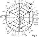
- the reinforcement ribs 24, 26, 28 may form a circular cobweb structure extending about a center 34 of the support layer 4.
- the cobweb structure has first reinforcement ribs 24 extending in a radial direction from the center 34 of the support layer 4 and second reinforcement ribs 26 extending in an essentially circumferential direction around the center 34 of the support layer 4.
- the second reinforcement ribs 26 have a linear extension extending perpendicular to an imaginary radial line 38 running in an equidistant manner between two neighbouring first reinforcement ribs 24.
- the second reinforcement ribs 26 run essentially perpendicular to the respective first reinforcement ribs 24 at the points of intersection with the first reinforcement ribs 24.
- the wording "essentially perpendicular" comprises angles of approximately 50° to 130°, preferably between 70° and 110°. In the embodiment of Fig. 6 the angle between the first and second reinforcement ribs 24, 26 is about 60°.
- the cob web structure has proved to provide for a particularly stiff and flexural rigid support layer 4 and backing pad 2, respectively.
- the reinforcement ribs 24, 26, 28 comprise first reinforcement ribs 24 extending in a radial direction from a center 34 of the support layer 4 and first reinforcement ribs 24' extending parallel to an imaginary line 41 extending in a radial direction.
- the imaginary line 41 runs in an equidistant manner between two neighbouring first reinforcement ribs 24.
- the bottom surface 12 of the support layer 4 of Fig. 5 is divided into four separate quadrants by the first reinforcement ribs 24. Each quadrant comprises an imaginary line 41.
- the first reinforcement ribs 24' have different extensions depending on the quadrant they are in. In particular, the first reinforcement ribs 24' of a certain quadrant extend parallel to the imaginary line 41 of that quadrant.
- the rib structure of Figs. 1 and 5 further comprises second reinforcement ribs 26 extending in a circumferential direction around the center 34 of the support layer 4.
- the second reinforcement ribs 26 have a circular extension extending perpendicular to the first reinforcement ribs 24 and the imaginary radial lines 41 at the respective points of intersection.
- the second reinforcement ribs 26 do not run exactly perpendicular to the other first reinforcement ribs 24' at the points of intersection. Due to the first reinforcement ribs 24' not extending exactly radially, the second reinforcement ribs 26 will not run exactly perpendicular to the first reinforcement ribs 24' in their points of intersection.
- the wording "essentially perpendicular" comprises angles of approximately 50° to 130°, preferably between 70° and 110°.
- the first reinforcement ribs 24 extending in a radial direction may extend along the entire distance between a center 34 of the support layer 4 and an outer edge 40 of the support layer 4.
- the reinforcement ribs 24, 26, 28 comprise first reinforcement ribs 24 extending in a radial direction from a center 34 of the support layer 4 or parallel to the radial direction along at least part of a distance between the center 34 of the support layer 4 and an outer edge 40 of the support layer 4.
- the first reinforcement ribs 24 may start in a distance to the center 34 of the support layer 4 and/or end in a distance to the outer edge 40 of the support layer 4.
- the first reinforcement ribs 24 are equally spaced apart in respect to each other in a circumferential direction (see Figs. 1 , 3 , 5 (regarding the first ribs 24, not the other first ribs 24'), and 6). This provides for reinforcement ribs 24 evenly distributed on the bottom surface 12 of the support layer 4 and for an amount of stiffness and flexural rigidity of the support layer 4 and the backing pad 2, respectively, evenly distributed in discrete rotational angles about the center 34 of the support layer 4.
- the second reinforcement ribs 26 may extend coaxially around the center 34 of the support layer 4. This provides for an even and uniform distribution of the weight of the backing pad 2 in respect to the center axis 22 of the support layer 4 resulting in a minimum of vibrations during rotation of the backing pad 2 about its rotational axis 22 running through the center 34 of the support layer 4. Neighbouring second reinforcement ribs 26 are spaced apart from each other in a radial direction, preferably by an equal distance. Of course, it would also be possible to design the reinforcement rib structure such that neighbouring second circumferential reinforcement ribs 26 towards the center 34 of the support layer 4 have a larger distance than neighbouring second circumferential reinforcement ribs 26 towards the outer edge 40 of the support layer 4 or vice versa.
- the reinforcement ribs 24, 26, 28 may comprise third reinforcement ribs 28 which are embodied as circular, semi-circular or oval ribs located at least at some intersection points between radially extending first reinforcement ribs 24 (see Figs. 3 and 6 ) or first reinforcement ribs 24' (see Fig. 5 ) extending parallel to a radial direction 41 and circumferentially extending second reinforcement ribs 26, wherein the intersection points form centers of the third reinforcement ribs 28.
- the third reinforcement ribs 28 add additional stiffness and flexural rigidity to the support layer 5 and the backing pad 2, respectively.
- the third reinforcement ribs 28 mostly have a circular shape.
- the circular third ribs 28 are located at each point of intersection between the first radial ribs 24 and the second circumferential ribs 26.
- the third reinforcement ribs 28 may have the form of a semi-circle or a semi-oval (see Fig. 3 ).
- the center of the semi-oval external third ribs 28 is constituted by a point of intersection between the first radial ribs 24 and the outer edge 40 of the support layer 4.
- the third reinforcement ribs 28 all have a circular shape.
- the circular third ribs 28 are located only at some points of intersection between the first radial ribs 24 and the other first ribs 24' extending parallel to a radial imaginary line 41 and at some points of intersection of the other first ribs 24' extending parallel to a radial imaginary line 41 and the second circumferential ribs 26.
- the third reinforcement ribs 28 have an oval shape.
- the oval third ribs 28 are located only at some points of intersection between the first radial ribs 24 and the second essentially circumferential ribs 26.
- the third reinforcement ribs 28 could also have the form of any polygon, in particular a polygon having more than three sides and corners.
- the third reinforcement ribs 28 could have the form of a rhombus with four sides and four corners.
- the reinforcement rib structure could be designed such that neighbouring third reinforcement ribs 28 touch in a common point or region of external walls forming the third reinforcement ribs 28.
- the third reinforcement ribs 28 of neighbouring intersection points are spaced apart from each other.
- the reinforcement rib structure could be designed such that at least some of the third reinforcement ribs 28 have a different form and/or diameter (see Fig. 3 ).
- the third reinforcement ribs 28 towards the center 34 of the support layer 4 are smaller than those located towards the outer edge 40 of the support layer 4.
- the third reinforcement ribs 28 have the same form and/or the same diameter throughout the entire bottom surface 12 of the support layer 4 (see Fig. 5 ).
- the backing pad 2 may have any given form, in particular rectangular or delta-shaped. Such backing pads 2 will not rotate about a central axis 22 of rotation but simply perform a purely orbital (or eccentric) working movement. To this end, they would be attached to an orbital polishing or sanding power tool. Preferably, in a top view, the backing pad 2 has a circular shape. Such a backing pad 2 may perform a purely orbital, a random-orbital or a roto-orbital (gear driven) working movement depending on the type of polishing or sanding power tool it is attached to or whether it is fixedly attached directly to a drive shaft 18 of the power tool (see Fig. 2 ) or - possibly in a freely rotatable manner - to an eccentric element which in turn is fixedly attached to the drive shaft 18 of the power tool.
- Manufacturing of the backing pad 2 may be performed in the following manner: First, a connection element 6 for connection of the backing pad 2 to a driving shaft 18 or an eccentric element of a polishing or sanding power tool may be inserted into the bottom of an injection mould. Then, the heated material of the support layer 4 is injected into the injection mould, surrounding at least part of the connection element 6. The bottom surface 12 of the support layer 4 faces upwards in the injection mould.
- the reinforcement ribs 24, 26, 28 are created, for example, by closing the injection mould with a lid having channels embodied therein corresponding to the reinforcement ribs 24, 26, 28. The lid is pressed onto the material of the support layer 4 whereby the material enters into the channels thereby forming the reinforcement ribs 24, 26, 28.
- the heated material of the damping layer 10 is injected into the injection mould on top of the bottom surface 12 of the support layer 4. If a lid was used for creating the reinforcement ribs 24, 26, 28, it must be removed before the material of the damping layer 10 can be inserted into the injection mould. Due to the fluid or viscous condition of the heated material of the damping layer 10, it enters into the recesses 30 between the reinforcement ribs 24, 26, 28 and fills them out completely.
- the adhesive layer 14 is positioned on the bottom surface 16 of the damping layer 10.
- the materials of the backing pad 2 are cured, possibly under heat supply and/or pressure. After curing of the materials the damping layer 10 is fixedly attached to the bottom surface 12 of the support layer 4 and the adhesive layer 14 is fixedly attached to the bottom surface 16 of the damping layer 10.
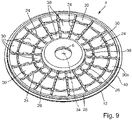
- Fig. 9 shows an embodiment of the backing pad 2 not making part of the present invention.
- the bottom surface 12 of the support layer 4 is provided with reinforcement elements in the form of reinforcement ribs 24, 26.
- the bottom surface 12 of the support layer 4 is further provided with recesses 30 formed between and at least partially limited by the reinforcement ribs 24, 26, wherein during manufacture of the backing pad 2 the resilient material of the damping layer 10 enters into the recesses 30 and after curing of the resilient material entirely fills the recesses 30.
- a surface of the reinforcement ribs 24, 26 facing away from the bottom surface 12 of the support layer 4 towards the damping layer 10 does not have an even but rather an undulated extension.
- the reinforcement ribs 24, 26 have their largest thickness at their respective intersections.
- the reinforcement elements comprise a plurality of first reinforcement ribs 24 extending in a radial direction from a center 34 of the support layer 4.
- the reinforcement elements further comprise second reinforcement ribs 26 having a circular extension extending equidistant to the center 34 and perpendicular to the first reinforcement ribs 24.
- a total of three second reinforcement ribs 24 are provided.
- Recesses 30 are formed between neighbouring first reinforcement ribs 24 and neighbouring second reinforcement ribs 26. Some recesses 30a are not limited to all sides by reinforcement ribs 24, 26, but instead open towards the outside/ environment. Only the external second reinforcement rib 26 has a surface with an even extension facing away from the bottom surface 12 of the support layer 4 towards the damping layer 10.
- Fig. 11 shows part of a bottom surface 12 of the support layer 4 of a backing pad 2 according to the invention, where the reinforcement elements comprise a plurality of discrete pyramid-shaped elements 46 having a base surface in the form of a rectangle, in particular a square.
- the base surface could also have the form of a circle, a triangle, or any other polygonal form, in particular an equilateral polygonal form.
- Side surfaces of the discrete elements 46 converge towards a tip 48 facing away from the bottom surface 12 of the support layer 4 towards the damping layer 10.
- Recesses 30 are formed between neighbouring discrete pyramid-shaped elements 46.
- Fig. 10 shows part of yet another embodiment of a bottom surface 12 of the support layer 4 of a backing pad 2 according to the invention, where the reinforcement elements comprise a plurality of discrete elements 50, 52 forming an undulated surface extension.
- the discrete elements 50, 52 comprise hills 50 protruding from the bottom surface 12 and valleys 52 in the form of depressions in the bottom surface 12.
- the discrete elements 50, 52 may be obtained by rounding of the edges of the pyramid-shaped elements 46 of Fig. 11 .
- the discrete elements 50, 52 are similar to the discrete elements 46 of Fig. 11 , with all edges rounded, in order to form the undulated structure on the bottom surface 12 of the support layer 4 of the backing pad 2.
- the discrete elements 50, 52 do not have to be aligned and arranged strictly next to each other. Instead, they can also be arranged offset to each other in respect to the plane of the bottom surface 12 of the support layer 4.
Landscapes
- Engineering & Computer Science (AREA)
- Mechanical Engineering (AREA)
- Manufacturing & Machinery (AREA)
- Polishing Bodies And Polishing Tools (AREA)
- Vibration Prevention Devices (AREA)
- Constituent Portions Of Griding Lathes, Driving, Sensing And Control (AREA)
- Finish Polishing, Edge Sharpening, And Grinding By Specific Grinding Devices (AREA)
Applications Claiming Priority (1)
| Application Number | Priority Date | Filing Date | Title |
|---|---|---|---|
| EP21161306.2A EP4056316B1 (de) | 2021-03-08 | 2021-03-08 | Stützunterlage für ein handgeführtes polier- oder schleifelektrowerkzeug |
Publications (4)
| Publication Number | Publication Date |
|---|---|
| EP4056317A2 true EP4056317A2 (de) | 2022-09-14 |
| EP4056317A3 EP4056317A3 (de) | 2022-11-23 |
| EP4056317B1 EP4056317B1 (de) | 2025-04-23 |
| EP4056317C0 EP4056317C0 (de) | 2025-04-23 |
Family
ID=74859816
Family Applications (3)
| Application Number | Title | Priority Date | Filing Date |
|---|---|---|---|
| EP21161306.2A Active EP4056316B1 (de) | 2021-03-08 | 2021-03-08 | Stützunterlage für ein handgeführtes polier- oder schleifelektrowerkzeug |
| EP22158628.2A Active EP4056317B1 (de) | 2021-03-08 | 2022-02-24 | Stützunterlage für ein handgeführtes polier- oder schleifelektrowerkzeug |
| EP22158633.2A Active EP4056318B1 (de) | 2021-03-08 | 2022-02-24 | Stützunterlage für ein handgeführtes polier- oder schleifelektrowerkzeug |
Family Applications Before (1)
| Application Number | Title | Priority Date | Filing Date |
|---|---|---|---|
| EP21161306.2A Active EP4056316B1 (de) | 2021-03-08 | 2021-03-08 | Stützunterlage für ein handgeführtes polier- oder schleifelektrowerkzeug |
Family Applications After (1)
| Application Number | Title | Priority Date | Filing Date |
|---|---|---|---|
| EP22158633.2A Active EP4056318B1 (de) | 2021-03-08 | 2022-02-24 | Stützunterlage für ein handgeführtes polier- oder schleifelektrowerkzeug |
Country Status (5)
| Country | Link |
|---|---|
| US (1) | US20220388122A1 (de) |
| EP (3) | EP4056316B1 (de) |
| JP (1) | JP7566809B2 (de) |
| KR (1) | KR20220126252A (de) |
| CN (1) | CN115106934B (de) |
Families Citing this family (2)
| Publication number | Priority date | Publication date | Assignee | Title |
|---|---|---|---|---|
| IT202200025119A1 (it) | 2022-12-06 | 2024-06-06 | Lucio Lupi | Tampone flessibile per la carteggiatura di carrozzerie |
| US12594574B2 (en) | 2023-07-25 | 2026-04-07 | The Boeing Company | Rotational applicator |
Citations (1)
| Publication number | Priority date | Publication date | Assignee | Title |
|---|---|---|---|---|
| US9039496B2 (en) | 2011-12-20 | 2015-05-26 | Kolthoff Gabrovo Eood | Grinding disk |
Family Cites Families (25)
| Publication number | Priority date | Publication date | Assignee | Title |
|---|---|---|---|---|
| US4138804A (en) * | 1976-11-05 | 1979-02-13 | Minnesota Mining And Manufacturing Company | Machine head assembly and torque-transmitting device incorporated in the same |
| IT1229703B (it) * | 1989-05-11 | 1991-09-07 | Franco Romanini | Utensile per levigatura o simili. |
| US5785784A (en) * | 1994-01-13 | 1998-07-28 | Minnesota Mining And Manufacturing Company | Abrasive articles method of making same and abrading apparatus |
| US6142858A (en) * | 1997-11-10 | 2000-11-07 | 3M Innovative Properties Company | Backup pad for abrasive articles |
| JPH11333696A (ja) * | 1998-05-26 | 1999-12-07 | Seiko Epson Corp | 研磨装置及び研磨方法 |
| KR100387954B1 (ko) * | 1999-10-12 | 2003-06-19 | (주) 휴네텍 | 연마패드용 컨디셔너와 이의 제조방법 |
| US6634937B1 (en) * | 2000-04-28 | 2003-10-21 | Toby Edwards | Clamping sander |
| US20030017291A1 (en) * | 2001-03-14 | 2003-01-23 | Fleming Danny L. | Adhesive layers and release liners with pyramidal structures |
| US20020195723A1 (en) * | 2001-06-25 | 2002-12-26 | Daniel Collette | Bond pad structure |
| US6755878B2 (en) * | 2002-08-02 | 2004-06-29 | 3M Innovative Properties Company | Abrasive articles and methods of making and using the same |
| JP3895256B2 (ja) * | 2002-10-11 | 2007-03-22 | Ykk株式会社 | 携行式研磨機用の研磨基板 |
| DE10357144A1 (de) * | 2003-12-06 | 2005-06-30 | Robert Bosch Gmbh | Schleifteller für eine Handschleifmaschine |
| TWI280175B (en) * | 2004-02-17 | 2007-05-01 | Skc Co Ltd | Base pad of polishing pad and multi-layer pad comprising the same |
| DE102007026841A1 (de) * | 2007-06-06 | 2008-12-11 | Satisloh Ag | Polierteller für ein Werkzeug zur Feinbearbeitung von optisch wirksamen Flächen an insbesondere Brillengläsern und Verfahren für dessen Herstellung |
| US8302243B2 (en) * | 2009-08-18 | 2012-11-06 | S.C. Johnson & Son, Inc. | Multi-layer surface treatment pad for motorized device |
| US20140179205A1 (en) * | 2012-12-20 | 2014-06-26 | Bach Pangho Chen | Grinding disc and method for manufacturing the same |
| JP6529210B2 (ja) * | 2013-04-04 | 2019-06-12 | スリーエム イノベイティブ プロパティズ カンパニー | 研磨ディスクを用いる研磨方法およびこれに用いる物品 |
| TWI599447B (zh) * | 2013-10-18 | 2017-09-21 | 卡博特微電子公司 | 具有偏移同心溝槽圖樣之邊緣排除區的cmp拋光墊 |
| JP6611414B2 (ja) * | 2014-05-27 | 2019-11-27 | スリーエム イノベイティブ プロパティズ カンパニー | 塗装表面の仕上げ方法及び研磨材料 |
| EP3028811B1 (de) * | 2014-12-05 | 2017-03-01 | Guido Valentini | Stützteller für ein handgeführtes Polier- oder Schleifwerkzeug und handgeführtes Polier- oder Schleifwerkzeug mit solch einem Stützteller |
| CN106334997A (zh) * | 2016-10-20 | 2017-01-18 | 天津华海清科机电科技有限公司 | 抛光头以及具有其的抛光机 |
| JP6580086B2 (ja) * | 2017-04-27 | 2019-09-25 | ケヰテック株式会社 | 複合スポンジバフ |
| DE202017107425U1 (de) * | 2017-12-06 | 2017-12-20 | Jobra Metall Gmbh | Schleifscheibe |
| DE102020207733A1 (de) * | 2019-09-04 | 2021-03-04 | Robert Bosch Gesellschaft mit beschränkter Haftung | Schleifwerkzeugvorrichtung, Schleifmittel und Schleifwerkzeugsystem |
| CN111070080B (zh) * | 2019-12-31 | 2022-02-22 | 天津大学 | 一种子孔径中心供液光学元件表面系列加工工艺 |
-
2021
- 2021-03-08 EP EP21161306.2A patent/EP4056316B1/de active Active
-
2022
- 2022-02-24 EP EP22158628.2A patent/EP4056317B1/de active Active
- 2022-02-24 EP EP22158633.2A patent/EP4056318B1/de active Active
- 2022-03-01 US US17/683,599 patent/US20220388122A1/en not_active Abandoned
- 2022-03-04 CN CN202210207973.7A patent/CN115106934B/zh active Active
- 2022-03-07 JP JP2022034168A patent/JP7566809B2/ja active Active
- 2022-03-08 KR KR1020220029471A patent/KR20220126252A/ko active Pending
Patent Citations (1)
| Publication number | Priority date | Publication date | Assignee | Title |
|---|---|---|---|---|
| US9039496B2 (en) | 2011-12-20 | 2015-05-26 | Kolthoff Gabrovo Eood | Grinding disk |
Also Published As
| Publication number | Publication date |
|---|---|
| KR20220126252A (ko) | 2022-09-15 |
| EP4056316B1 (de) | 2025-05-07 |
| EP4056316A1 (de) | 2022-09-14 |
| CN115106934B (zh) | 2024-10-18 |
| EP4056318A2 (de) | 2022-09-14 |
| EP4056316C0 (de) | 2025-05-07 |
| US20220388122A1 (en) | 2022-12-08 |
| EP4056318B1 (de) | 2025-04-23 |
| EP4056318A3 (de) | 2022-12-14 |
| CN115106934A (zh) | 2022-09-27 |
| JP7566809B2 (ja) | 2024-10-15 |
| JP2022136999A (ja) | 2022-09-21 |
| EP4056317B1 (de) | 2025-04-23 |
| EP4056318C0 (de) | 2025-04-23 |
| EP4056317C0 (de) | 2025-04-23 |
| EP4056317A3 (de) | 2022-11-23 |
Similar Documents
| Publication | Publication Date | Title |
|---|---|---|
| EP4056317B1 (de) | Stützunterlage für ein handgeführtes polier- oder schleifelektrowerkzeug | |
| US11383352B2 (en) | Polishing pad | |
| AU2002306908B2 (en) | Polishing pad and system | |
| US20080003929A1 (en) | Device for cutting and grinding, chucking device and rotating tool with vibration damping | |
| US9039496B2 (en) | Grinding disk | |
| US20130225051A1 (en) | Abrasive pad assembly | |
| JP2014200883A (ja) | 研磨ディスクを支持するためのパッド | |
| CA3017577C (en) | Grinding disc device for a grinding apparatus | |
| RU2664842C1 (ru) | Шлифовальный круг | |
| US20110021119A1 (en) | Grinding wheel assembly | |
| US9597776B2 (en) | Grinding disk | |
| EP1046467A1 (de) | Poliermaschine mit einem Drehkopf der eine Vielzahl von Poliersektoren mit segmentierten und elastischen Strukturen trägt | |
| ITBO20000520A1 (it) | Dispositivo per la smerigliatura e/o abrasione di superfici tramite macchine roto orbitali | |
| US20050188491A1 (en) | Buffing ball made of compressible material | |
| KR20230095999A (ko) | 연마 물품을 위한 재사용 가능한 허브 조립체 | |
| JP7420331B2 (ja) | ブラシユニット、ブラシユニット体及び研磨ブラシ | |
| US4651475A (en) | Honing tool | |
| EP4487998A1 (de) | Polierkissen zum polieren einer oberfläche eines werkstücks | |
| CN100509295C (zh) | 用于手操作的电动磨削工具机的磨削盘的盘内置件 | |
| JP2006000950A (ja) | 回転式研磨ロールの製造方法 | |
| JP2004174173A (ja) | 電動床磨機用回転ブラシ | |
| JP2006000949A (ja) | 回転式研磨ロール | |
| WO2019049033A1 (en) | SUPPORT DEVICE FOR ABRASIVE TOOL AND CORRESPONDING ABRASIVE TOOL | |
| JPS6235973Y2 (de) | ||
| JPS59175958A (ja) | 波状多層研削輪 |
Legal Events
| Date | Code | Title | Description |
|---|---|---|---|
| PUAI | Public reference made under article 153(3) epc to a published international application that has entered the european phase |
Free format text: ORIGINAL CODE: 0009012 |
|
| STAA | Information on the status of an ep patent application or granted ep patent |
Free format text: STATUS: THE APPLICATION HAS BEEN PUBLISHED |
|
| AK | Designated contracting states |
Kind code of ref document: A2 Designated state(s): AL AT BE BG CH CY CZ DE DK EE ES FI FR GB GR HR HU IE IS IT LI LT LU LV MC MK MT NL NO PL PT RO RS SE SI SK SM TR |
|
| PUAL | Search report despatched |
Free format text: ORIGINAL CODE: 0009013 |
|
| AK | Designated contracting states |
Kind code of ref document: A3 Designated state(s): AL AT BE BG CH CY CZ DE DK EE ES FI FR GB GR HR HU IE IS IT LI LT LU LV MC MK MT NL NO PL PT RO RS SE SI SK SM TR |
|
| RIC1 | Information provided on ipc code assigned before grant |
Ipc: B24D 18/00 20060101ALI20221019BHEP Ipc: B24D 9/08 20060101AFI20221019BHEP |
|
| STAA | Information on the status of an ep patent application or granted ep patent |
Free format text: STATUS: REQUEST FOR EXAMINATION WAS MADE |
|
| 17P | Request for examination filed |
Effective date: 20230426 |
|
| RBV | Designated contracting states (corrected) |
Designated state(s): AL AT BE BG CH CY CZ DE DK EE ES FI FR GB GR HR HU IE IS IT LI LT LU LV MC MK MT NL NO PL PT RO RS SE SI SK SM TR |
|
| P01 | Opt-out of the competence of the unified patent court (upc) registered |
Effective date: 20230508 |
|
| GRAP | Despatch of communication of intention to grant a patent |
Free format text: ORIGINAL CODE: EPIDOSNIGR1 |
|
| STAA | Information on the status of an ep patent application or granted ep patent |
Free format text: STATUS: GRANT OF PATENT IS INTENDED |
|
| GRAS | Grant fee paid |
Free format text: ORIGINAL CODE: EPIDOSNIGR3 |
|
| INTG | Intention to grant announced |
Effective date: 20250214 |
|
| GRAA | (expected) grant |
Free format text: ORIGINAL CODE: 0009210 |
|
| STAA | Information on the status of an ep patent application or granted ep patent |
Free format text: STATUS: THE PATENT HAS BEEN GRANTED |
|
| AK | Designated contracting states |
Kind code of ref document: B1 Designated state(s): AL AT BE BG CH CY CZ DE DK EE ES FI FR GB GR HR HU IE IS IT LI LT LU LV MC MK MT NL NO PL PT RO RS SE SI SK SM TR |
|
| REG | Reference to a national code |
Ref country code: GB Ref legal event code: FG4D |
|
| REG | Reference to a national code |
Ref country code: CH Ref legal event code: EP |
|
| REG | Reference to a national code |
Ref country code: DE Ref legal event code: R096 Ref document number: 602022013377 Country of ref document: DE |
|
| REG | Reference to a national code |
Ref country code: IE Ref legal event code: FG4D |
|
| P04 | Withdrawal of opt-out of the competence of the unified patent court (upc) registered |
Free format text: CASE NUMBER: APP_20526/2025 Effective date: 20250430 |
|
| U01 | Request for unitary effect filed |
Effective date: 20250425 |
|
| U07 | Unitary effect registered |
Designated state(s): AT BE BG DE DK EE FI FR IT LT LU LV MT NL PT RO SE SI Effective date: 20250506 |
|
| PG25 | Lapsed in a contracting state [announced via postgrant information from national office to epo] |
Ref country code: ES Free format text: LAPSE BECAUSE OF FAILURE TO SUBMIT A TRANSLATION OF THE DESCRIPTION OR TO PAY THE FEE WITHIN THE PRESCRIBED TIME-LIMIT Effective date: 20250423 |
|
| PG25 | Lapsed in a contracting state [announced via postgrant information from national office to epo] |
Ref country code: NO Free format text: LAPSE BECAUSE OF FAILURE TO SUBMIT A TRANSLATION OF THE DESCRIPTION OR TO PAY THE FEE WITHIN THE PRESCRIBED TIME-LIMIT Effective date: 20250723 Ref country code: GR Free format text: LAPSE BECAUSE OF FAILURE TO SUBMIT A TRANSLATION OF THE DESCRIPTION OR TO PAY THE FEE WITHIN THE PRESCRIBED TIME-LIMIT Effective date: 20250724 |
|
| PG25 | Lapsed in a contracting state [announced via postgrant information from national office to epo] |
Ref country code: PL Free format text: LAPSE BECAUSE OF FAILURE TO SUBMIT A TRANSLATION OF THE DESCRIPTION OR TO PAY THE FEE WITHIN THE PRESCRIBED TIME-LIMIT Effective date: 20250423 |
|
| PG25 | Lapsed in a contracting state [announced via postgrant information from national office to epo] |
Ref country code: HR Free format text: LAPSE BECAUSE OF FAILURE TO SUBMIT A TRANSLATION OF THE DESCRIPTION OR TO PAY THE FEE WITHIN THE PRESCRIBED TIME-LIMIT Effective date: 20250423 |
|
| PG25 | Lapsed in a contracting state [announced via postgrant information from national office to epo] |
Ref country code: RS Free format text: LAPSE BECAUSE OF FAILURE TO SUBMIT A TRANSLATION OF THE DESCRIPTION OR TO PAY THE FEE WITHIN THE PRESCRIBED TIME-LIMIT Effective date: 20250723 |
|
| PG25 | Lapsed in a contracting state [announced via postgrant information from national office to epo] |
Ref country code: IS Free format text: LAPSE BECAUSE OF FAILURE TO SUBMIT A TRANSLATION OF THE DESCRIPTION OR TO PAY THE FEE WITHIN THE PRESCRIBED TIME-LIMIT Effective date: 20250823 |
|
| PG25 | Lapsed in a contracting state [announced via postgrant information from national office to epo] |
Ref country code: SM Free format text: LAPSE BECAUSE OF FAILURE TO SUBMIT A TRANSLATION OF THE DESCRIPTION OR TO PAY THE FEE WITHIN THE PRESCRIBED TIME-LIMIT Effective date: 20250423 |
|
| PG25 | Lapsed in a contracting state [announced via postgrant information from national office to epo] |
Ref country code: CZ Free format text: LAPSE BECAUSE OF FAILURE TO SUBMIT A TRANSLATION OF THE DESCRIPTION OR TO PAY THE FEE WITHIN THE PRESCRIBED TIME-LIMIT Effective date: 20250423 |
|
| PG25 | Lapsed in a contracting state [announced via postgrant information from national office to epo] |
Ref country code: SK Free format text: LAPSE BECAUSE OF FAILURE TO SUBMIT A TRANSLATION OF THE DESCRIPTION OR TO PAY THE FEE WITHIN THE PRESCRIBED TIME-LIMIT Effective date: 20250423 |
|
| PLBE | No opposition filed within time limit |
Free format text: ORIGINAL CODE: 0009261 |
|
| STAA | Information on the status of an ep patent application or granted ep patent |
Free format text: STATUS: NO OPPOSITION FILED WITHIN TIME LIMIT |
|
| REG | Reference to a national code |
Ref country code: CH Ref legal event code: L10 Free format text: ST27 STATUS EVENT CODE: U-0-0-L10-L00 (AS PROVIDED BY THE NATIONAL OFFICE) Effective date: 20260304 |
|
| 26N | No opposition filed |
Effective date: 20260126 |
|
| U20 | Renewal fee for the european patent with unitary effect paid |
Year of fee payment: 5 Effective date: 20260225 |