EP4056094A1 - Reinigungsroboter für eine gepolsterte fläche - Google Patents
Reinigungsroboter für eine gepolsterte fläche Download PDFInfo
- Publication number
- EP4056094A1 EP4056094A1 EP22166044.2A EP22166044A EP4056094A1 EP 4056094 A1 EP4056094 A1 EP 4056094A1 EP 22166044 A EP22166044 A EP 22166044A EP 4056094 A1 EP4056094 A1 EP 4056094A1
- Authority
- EP
- European Patent Office
- Prior art keywords
- area
- cleaning robot
- obstacle
- mites
- cleaning
- Prior art date
- Legal status (The legal status is an assumption and is not a legal conclusion. Google has not performed a legal analysis and makes no representation as to the accuracy of the status listed.)
- Granted
Links
Images

Classifications
-
- A—HUMAN NECESSITIES
- A47—FURNITURE; DOMESTIC ARTICLES OR APPLIANCES; COFFEE MILLS; SPICE MILLS; SUCTION CLEANERS IN GENERAL
- A47L—DOMESTIC WASHING OR CLEANING; SUCTION CLEANERS IN GENERAL
- A47L11/00—Machines for cleaning floors, carpets, furniture, walls, or wall coverings
-
- A—HUMAN NECESSITIES
- A01—AGRICULTURE; FORESTRY; ANIMAL HUSBANDRY; HUNTING; TRAPPING; FISHING
- A01M—CATCHING, TRAPPING OR SCARING OF ANIMALS; APPARATUS FOR THE DESTRUCTION OF NOXIOUS ANIMALS OR NOXIOUS PLANTS
- A01M1/00—Stationary means for catching or killing insects
- A01M1/02—Stationary means for catching or killing insects with devices or substances, e.g. food, pheronones attracting the insects
-
- A—HUMAN NECESSITIES
- A01—AGRICULTURE; FORESTRY; ANIMAL HUSBANDRY; HUNTING; TRAPPING; FISHING
- A01M—CATCHING, TRAPPING OR SCARING OF ANIMALS; APPARATUS FOR THE DESTRUCTION OF NOXIOUS ANIMALS OR NOXIOUS PLANTS
- A01M1/00—Stationary means for catching or killing insects
- A01M1/02—Stationary means for catching or killing insects with devices or substances, e.g. food, pheronones attracting the insects
- A01M1/04—Attracting insects by using illumination or colours
-
- A—HUMAN NECESSITIES
- A01—AGRICULTURE; FORESTRY; ANIMAL HUSBANDRY; HUNTING; TRAPPING; FISHING
- A01M—CATCHING, TRAPPING OR SCARING OF ANIMALS; APPARATUS FOR THE DESTRUCTION OF NOXIOUS ANIMALS OR NOXIOUS PLANTS
- A01M17/00—Apparatus for the destruction of vermin in soil or in foodstuffs
- A01M17/006—Destruction of vermin in clothes
-
- A—HUMAN NECESSITIES
- A47—FURNITURE; DOMESTIC ARTICLES OR APPLIANCES; COFFEE MILLS; SPICE MILLS; SUCTION CLEANERS IN GENERAL
- A47L—DOMESTIC WASHING OR CLEANING; SUCTION CLEANERS IN GENERAL
- A47L11/00—Machines for cleaning floors, carpets, furniture, walls, or wall coverings
- A47L11/24—Floor-sweeping machines, motor-driven
-
- A—HUMAN NECESSITIES
- A47—FURNITURE; DOMESTIC ARTICLES OR APPLIANCES; COFFEE MILLS; SPICE MILLS; SUCTION CLEANERS IN GENERAL
- A47L—DOMESTIC WASHING OR CLEANING; SUCTION CLEANERS IN GENERAL
- A47L11/00—Machines for cleaning floors, carpets, furniture, walls, or wall coverings
- A47L11/40—Parts or details of machines not provided for in groups A47L11/02 - A47L11/38, or not restricted to one of these groups, e.g. handles, arrangements of switches, skirts, buffers, levers
-
- A—HUMAN NECESSITIES
- A47—FURNITURE; DOMESTIC ARTICLES OR APPLIANCES; COFFEE MILLS; SPICE MILLS; SUCTION CLEANERS IN GENERAL
- A47L—DOMESTIC WASHING OR CLEANING; SUCTION CLEANERS IN GENERAL
- A47L11/00—Machines for cleaning floors, carpets, furniture, walls, or wall coverings
- A47L11/40—Parts or details of machines not provided for in groups A47L11/02 - A47L11/38, or not restricted to one of these groups, e.g. handles, arrangements of switches, skirts, buffers, levers
- A47L11/4011—Regulation of the cleaning machine by electric means; Control systems and remote control systems therefor
-
- A—HUMAN NECESSITIES
- A47—FURNITURE; DOMESTIC ARTICLES OR APPLIANCES; COFFEE MILLS; SPICE MILLS; SUCTION CLEANERS IN GENERAL
- A47L—DOMESTIC WASHING OR CLEANING; SUCTION CLEANERS IN GENERAL
- A47L11/00—Machines for cleaning floors, carpets, furniture, walls, or wall coverings
- A47L11/40—Parts or details of machines not provided for in groups A47L11/02 - A47L11/38, or not restricted to one of these groups, e.g. handles, arrangements of switches, skirts, buffers, levers
- A47L11/4027—Filtering or separating contaminants or debris
-
- A—HUMAN NECESSITIES
- A47—FURNITURE; DOMESTIC ARTICLES OR APPLIANCES; COFFEE MILLS; SPICE MILLS; SUCTION CLEANERS IN GENERAL
- A47L—DOMESTIC WASHING OR CLEANING; SUCTION CLEANERS IN GENERAL
- A47L11/00—Machines for cleaning floors, carpets, furniture, walls, or wall coverings
- A47L11/40—Parts or details of machines not provided for in groups A47L11/02 - A47L11/38, or not restricted to one of these groups, e.g. handles, arrangements of switches, skirts, buffers, levers
- A47L11/4036—Parts or details of the surface treating tools
-
- A—HUMAN NECESSITIES
- A47—FURNITURE; DOMESTIC ARTICLES OR APPLIANCES; COFFEE MILLS; SPICE MILLS; SUCTION CLEANERS IN GENERAL
- A47L—DOMESTIC WASHING OR CLEANING; SUCTION CLEANERS IN GENERAL
- A47L11/00—Machines for cleaning floors, carpets, furniture, walls, or wall coverings
- A47L11/40—Parts or details of machines not provided for in groups A47L11/02 - A47L11/38, or not restricted to one of these groups, e.g. handles, arrangements of switches, skirts, buffers, levers
- A47L11/4036—Parts or details of the surface treating tools
- A47L11/405—Machines using UV-lamps, IR-lamps, ultrasound or plasma cleaning
-
- A—HUMAN NECESSITIES
- A47—FURNITURE; DOMESTIC ARTICLES OR APPLIANCES; COFFEE MILLS; SPICE MILLS; SUCTION CLEANERS IN GENERAL
- A47L—DOMESTIC WASHING OR CLEANING; SUCTION CLEANERS IN GENERAL
- A47L11/00—Machines for cleaning floors, carpets, furniture, walls, or wall coverings
- A47L11/40—Parts or details of machines not provided for in groups A47L11/02 - A47L11/38, or not restricted to one of these groups, e.g. handles, arrangements of switches, skirts, buffers, levers
- A47L11/4061—Steering means; Means for avoiding obstacles; Details related to the place where the driver is accommodated
-
- A—HUMAN NECESSITIES
- A47—FURNITURE; DOMESTIC ARTICLES OR APPLIANCES; COFFEE MILLS; SPICE MILLS; SUCTION CLEANERS IN GENERAL
- A47L—DOMESTIC WASHING OR CLEANING; SUCTION CLEANERS IN GENERAL
- A47L11/00—Machines for cleaning floors, carpets, furniture, walls, or wall coverings
- A47L11/40—Parts or details of machines not provided for in groups A47L11/02 - A47L11/38, or not restricted to one of these groups, e.g. handles, arrangements of switches, skirts, buffers, levers
- A47L11/4072—Arrangement of castors or wheels
-
- A—HUMAN NECESSITIES
- A47—FURNITURE; DOMESTIC ARTICLES OR APPLIANCES; COFFEE MILLS; SPICE MILLS; SUCTION CLEANERS IN GENERAL
- A47L—DOMESTIC WASHING OR CLEANING; SUCTION CLEANERS IN GENERAL
- A47L11/00—Machines for cleaning floors, carpets, furniture, walls, or wall coverings
- A47L11/40—Parts or details of machines not provided for in groups A47L11/02 - A47L11/38, or not restricted to one of these groups, e.g. handles, arrangements of switches, skirts, buffers, levers
- A47L11/408—Means for supplying cleaning or surface treating agents
-
- A—HUMAN NECESSITIES
- A01—AGRICULTURE; FORESTRY; ANIMAL HUSBANDRY; HUNTING; TRAPPING; FISHING
- A01M—CATCHING, TRAPPING OR SCARING OF ANIMALS; APPARATUS FOR THE DESTRUCTION OF NOXIOUS ANIMALS OR NOXIOUS PLANTS
- A01M1/00—Stationary means for catching or killing insects
- A01M1/08—Attracting and catching insects by using combined illumination or colours and suction effects
-
- A—HUMAN NECESSITIES
- A01—AGRICULTURE; FORESTRY; ANIMAL HUSBANDRY; HUNTING; TRAPPING; FISHING
- A01M—CATCHING, TRAPPING OR SCARING OF ANIMALS; APPARATUS FOR THE DESTRUCTION OF NOXIOUS ANIMALS OR NOXIOUS PLANTS
- A01M1/00—Stationary means for catching or killing insects
- A01M1/22—Killing insects by electric means
- A01M1/226—Killing insects by electric means by using waves, fields or rays, e.g. sound waves, microwaves, electric waves, magnetic fields, light rays
-
- A—HUMAN NECESSITIES
- A47—FURNITURE; DOMESTIC ARTICLES OR APPLIANCES; COFFEE MILLS; SPICE MILLS; SUCTION CLEANERS IN GENERAL
- A47L—DOMESTIC WASHING OR CLEANING; SUCTION CLEANERS IN GENERAL
- A47L2201/00—Robotic cleaning machines, i.e. with automatic control of the travelling movement or the cleaning operation
-
- A—HUMAN NECESSITIES
- A47—FURNITURE; DOMESTIC ARTICLES OR APPLIANCES; COFFEE MILLS; SPICE MILLS; SUCTION CLEANERS IN GENERAL
- A47L—DOMESTIC WASHING OR CLEANING; SUCTION CLEANERS IN GENERAL
- A47L2201/00—Robotic cleaning machines, i.e. with automatic control of the travelling movement or the cleaning operation
- A47L2201/04—Automatic control of the travelling movement; Automatic obstacle detection
-
- A—HUMAN NECESSITIES
- A47—FURNITURE; DOMESTIC ARTICLES OR APPLIANCES; COFFEE MILLS; SPICE MILLS; SUCTION CLEANERS IN GENERAL
- A47L—DOMESTIC WASHING OR CLEANING; SUCTION CLEANERS IN GENERAL
- A47L2201/00—Robotic cleaning machines, i.e. with automatic control of the travelling movement or the cleaning operation
- A47L2201/06—Control of the cleaning action for autonomous devices; Automatic detection of the surface condition before, during or after cleaning
-
- A—HUMAN NECESSITIES
- A61—MEDICAL OR VETERINARY SCIENCE; HYGIENE
- A61L—METHODS OR APPARATUS FOR STERILISING MATERIALS OR OBJECTS IN GENERAL; DISINFECTION, STERILISATION OR DEODORISATION OF AIR; CHEMICAL ASPECTS OF BANDAGES, DRESSINGS, ABSORBENT PADS OR SURGICAL ARTICLES; MATERIALS FOR BANDAGES, DRESSINGS, ABSORBENT PADS OR SURGICAL ARTICLES
- A61L2/00—Disinfection or sterilisation of materials or objects, in general; Accessories therefor
- A61L2/02—Disinfection or sterilisation of materials or objects, in general; Accessories therefor using physical processes
- A61L2/14—Plasma, i.e. ionised gases
-
- A—HUMAN NECESSITIES
- A61—MEDICAL OR VETERINARY SCIENCE; HYGIENE
- A61L—METHODS OR APPARATUS FOR STERILISING MATERIALS OR OBJECTS IN GENERAL; DISINFECTION, STERILISATION OR DEODORISATION OF AIR; CHEMICAL ASPECTS OF BANDAGES, DRESSINGS, ABSORBENT PADS OR SURGICAL ARTICLES; MATERIALS FOR BANDAGES, DRESSINGS, ABSORBENT PADS OR SURGICAL ARTICLES
- A61L2103/00—Materials or objects being the target of disinfection or sterilisation
- A61L2103/50—Textiles, e.g. bedwear or towels
-
- A—HUMAN NECESSITIES
- A61—MEDICAL OR VETERINARY SCIENCE; HYGIENE
- A61L—METHODS OR APPARATUS FOR STERILISING MATERIALS OR OBJECTS IN GENERAL; DISINFECTION, STERILISATION OR DEODORISATION OF AIR; CHEMICAL ASPECTS OF BANDAGES, DRESSINGS, ABSORBENT PADS OR SURGICAL ARTICLES; MATERIALS FOR BANDAGES, DRESSINGS, ABSORBENT PADS OR SURGICAL ARTICLES
- A61L2202/00—Aspects relating to methods or apparatus for disinfecting or sterilising materials or objects
- A61L2202/10—Apparatus features
- A61L2202/17—Combination with washing or cleaning means
Definitions
- the invention relates to a method for controlling a cleaning robot with a cleaning device over an area.
- the invention relates to a method of dispensing an attractant for mites.
- a household there is one or more upholstered pieces of furniture, such as a sofa, an armchair or a bed.
- upholstered pieces of furniture such as a sofa, an armchair or a bed.
- small creatures that have nested in an upholstered surface, in particular mites often cannot be adequately removed.
- the mites which feed mainly on skin flakes, do not in themselves pose a danger to humans, their excretions are highly allergenic, so that there is a risk that a user of such upholstered furniture will suffer from allergic symptoms.
- UV light can be emitted by an autonomous robot when driving over the area.
- such short wavelength light can be harmful if it gets into the eyes of a human or pet and can cause irritation or skin irritation even if left on unprotected skin for an extended period of time.
- a non-thermal plasma to control mites.
- this can release ozone, which, even in low concentrations, can cause a stimulating climate for people with health problems.
- a comprehensive treatment of a surface of upholstered furniture with ultraviolet light or with plasma can be energy-intensive or time-consuming.
- a robot can require a lot of energy to clean a larger piece of upholstered furniture, such as a double bed, so it may need a large energy store.
- a smaller energy store may have to be recharged before the end of the cleaning, so that the cleaning can take a very long time.
- a cleaning robot comprises a drive device for an upholstered surface; a control device for guiding the cleaning robot over the surface to be cleaned; a cleaning device which is set up to combat mites in the area of the surface; and a mite attractant dispenser.
- the control device is set up to dispense bait on the surface and to activate the cleaning device in the area of the bait dispensed after a predetermined waiting time. Controlling may include ingesting and/or disabling or destroying mites.
- the upholstered surface can in particular include furniture for sitting or lying down, such as an armchair, a couch, a chair or a bed.
- the upholstered surface may also cover a floor and may include, for example, a rug or carpeted floor.
- the area is preferably present in a household, in particular a private household.
- Controlling may include inactivating mites.
- a mite When inactivating, a mite can be treated in such a way that its harmful effect is minimized as much as possible.
- the harmful effect of a mite can consist in the spread of excretions that can have an allergenic effect, especially faeces, on the surface.
- Inactivation can immobilize a mite, greatly reducing its damage to the area.
- inactivation can damage the mite to such an extent that it no longer has any significant metabolism.
- excretion of excrement can be prevented.
- Inactivating may also include killing.
- the cleaning device is preferably set up to remove mites from the surface.
- An inactivated mite can no longer actively remain on the surface, so it can be removed better.
- Mites and/or dirt removed from the surface can be collected in a container.
- solids can be separated from air sucked off on the surface, for example by a deep-bed filter or a cyclone filter. The previous inactivation can prevent mites from escaping the container.
- Removal of mites can be done on a part of the area where attractant was previously applied. In one embodiment, removal may be omitted from a portion of the area where no attractant was previously applied.
- a device for deploying bait can have a predetermined processing range, and a device for combating and in particular inactivating can have a corresponding processing range.
- the mites can also be removed at a corresponding processing width. The surface can be cleaned more efficiently thanks to the corresponding processing widths. Effort to move the cleaning robot across the surface can be minimized.
- the attractant is preferably designed not to damage the mites.
- the attractant may not be toxic to mites. As a result, it is not necessary to wait until the attractant has had an inactivating effect. In addition, it may be easier to provide a pure attractant than an attractant with a damaging effect.
- the inactivation of the mites is preferably carried out by means of an electromechanical device which can provide, for example, a non-thermal plasma, as detailed below.
- the control device is preferably set up to minimize, ideally completely suppress, any emission of sound or vibrations by the cleaning robot during the waiting time. This can help attract mites.
- the absence of sound waves or vibrations, which can cause a mite to stay still, hide, hold, or flee, can attract the mites more effectively.
- a larger number of mites can be attracted, or a waiting time required for attracting the mites can be shortened.
- the control device is set up to dispense the lure at a predetermined point on the upholstered surface.
- the location may be determined depending on a type of the upholstered surface. If the surface is part of a chair or an armchair, for example, the position can be in an area on which the thighs of a person sitting on it usually rest. If the surface is part of a bed, the position can be, for example, in a head area, a torso area or a foot area of a person lying in bed. Corresponding areas or positions can be assigned to other upholstered surfaces. In this way, mites can be combated in particular where they are more likely to occur or in greater numbers. The fight against the mites can be more efficient.
- the cleaning device is set up to provide a non-thermal plasma.
- the plasma can be provided in such a way that mites are controlled and preferably inactivated.
- a non-thermal plasma also: cold atmospheric plasma or low-temperature plasma, NTP
- NTP low-temperature plasma
- the temperatures of particle types differ significantly.
- a cold atmospheric plasma produces a reactive mixture of plasma components such as electrons, ions, excited atoms and molecules, reactive species (such as O 3 , NO, NO 2 , etc.), UV radiation and heat. This mixture can be used to effectively destroy bacteria, fungi, viruses, spores or odor molecules.
- NTP Newcastle disease virus
- pathogens can even be killed through clothing or bed linen in a time-saving manner at a temperature of below 100°C.
- Small, multicellular creatures such as mites can also be killed using NTP.
- a major advantage of non-thermal plasma is that it is close to room temperature and can be produced at atmospheric pressure on Earth.
- a gas can be partially ironized so that only about one particle in 10 9 is ionized.
- proportions of included plasma components can vary or be changed in a targeted manner. In this way, a concentration or composition of plasma components can be adapted to a targeted application.
- the plasma can be used efficiently against mites without risking any health damage to a person in the area.
- the surface can be disinfected by means of the plasma.
- the cleaning device comprises a non-thermal plasma source that works on the basis of surface microdischarges.
- a plasma source is, for example, in EP 3 326 436 A1 shown.
- Such plasma sources can get by with a relatively low electrical voltage and work in an energy-saving manner, so that they are suitable for battery operation.
- the size of an electrode at which the plasma is provided can be varied within wide limits.
- the electrode itself can be made flat and flexible.
- an alternative technology for providing a non-thermal plasma can also be used, for example a magnetically organized plasma layer technology, a microwave plasma technology or a venturi plasma technology.
- the cleaning robot further preferably comprises a blower for sucking air out of the area of the surface.
- the blower can in particular be comprised of a suction unit, as is known from a vacuum cleaning robot.
- the mites can be picked up in the area of the surface by means of the blower.
- the mites that have been picked up, any remaining attractant and/or additionally picked up dirt particles are preferably separated from the sucked-in air and taken up in a container. This makes it easier to clean the upholstered surface.
- a device for detaching objects from the surface can be provided, for example a brush or a broom.
- the device can be movable in order to be moved by the cleaning robot in relation to the surface. Dirt, particles or mites can thus be better removed from the surface. In particular if the surface includes a textile, this can be cleaned better by the device.
- the device can be driven in an oscillating or rotating manner and can be realized, for example, as a brush or bristle roller.
- the cleaning robot also includes a filter for the extracted air.
- a filter for the extracted air.
- a first filter can be provided to retain dust, dirt particles or mites that have been picked up.
- a filter can be designed in particular as a fleece filter, pore filter or cyclone filter.
- This or a second filter can be set up to retain ozone from the extracted air and can include an activated carbon filter, for example. Ozone, which can be formed when cold plasma is provided at the cleaning device, can thus be prevented from spreading in the area of the upholstered surface and being ingested by a person.
- the cleaning robot is preferably set up for autonomous operation on the padded surface.
- the cleaning robot can include a special drive device in order to prevent it from sinking into a very soft upholstery, for example, and becoming unable to manoeuvre.
- the drive device comprises at least one, but preferably two, parallel chain drives.
- the track undercarriage may include a track, a drive wheel, an idler wheel, and two or more rollers. Due to its large contact surface on the padded surface, the track chain can only cause a low specific ground pressure, so that the cleaning robot can remain manoeuvrable even on very soft or slippery surfaces.
- the cleaning robot has at least one sensor for determining a boundary of the area.
- Different boundaries can be distinguished, in particular a step that extends downwards from the surface and a threshold that extends upwards.
- a step can be formed at the end of a mattress, for example.
- a threshold can be formed by a footboard or a headboard of a bed in which there is a mattress whose surface can be processed.
- a method for controlling a cleaning robot with a cleaning device over an area comprises the steps of driving the cleaning robot straight ahead until it reaches an obstacle and determining an obstacle position; changing the direction of travel by a predetermined angle and repeating the previous step until sufficient obstacle locations have been determined to define boundaries of the area determine; and guiding the cleaning robot on the area depending on its determined boundaries.
- a control device of the cleaning robot can include a processing device that is set up to carry out a method described herein in whole or in part.
- the processing device can comprise a programmable microcomputer or microcontroller and the method can be present in the form of a computer program product with program code means.
- the computer program product can also be stored on a computer-readable data carrier.
- a mite attractant is dispensed at an area or position on the surface; and that after a predetermined waiting time after dispensing, a cleaning device of the cleaning robot is activated in the area of the dispensed lure.
- the position or area may be determined based on an area boundary determination method described herein or otherwise. It is further preferred that the cleaning robot is driven away from the position during the waiting time. For example, attractant can be dispensed at several positions one after the other and later removed again by means of the cleaning device.
- the cleaning robot can travel over a remaining area of the surface to be cleaned during the waiting time and, in particular, treat it using the cleaning device.
- the waiting time is between applying the attractant and fighting the mites.
- combating can include inactivation, optionally killing, and further optionally removal, particularly suction, as described in more detail herein.
- the inactivation or killing is preferably carried out by means of a non-thermal plasma.
- the cleaning robot can carry out a predetermined movement after applying lure and before cleaning the area in order to better prepare mites for inactivation and/or removal.
- Mites can have limited mobility. They may be attracted to the lure and/or scared away by sound or vibration.
- the robotic cleaner can use the vibrations or noise inherent in its movement to drive the mites towards the area where the lure has been applied or to concentrate them in the area.
- the cleaning robot can drive around the area, optionally several times and with a decreasing distance, for example in a spiral. Movement can be continued into the area to ideally collect the mites at a predetermined position in the area.
- the cleaning robot can also be controlled to clean a surrounding area, in particular by means of suction.
- humidity in the surrounding area can be reduced, so that the non-vacuumed area is more attractive to mites than the dried surrounding area.
- a concentration of the mites in the area provided with the attractant can thereby be further improved.
- the cleaning of the surrounding area can be done together with the systematic driving of mites towards the baited area.
- the cleaning robot Before and/or after the predetermined movement, the cleaning robot can be put into a quiet mode during a predetermined waiting time, in which it emits as little or no vibration and/or sound as possible in order not to scare away the mites from the area. Finally, the mites can be inactivated and/or removed by means of the cleaning device.
- the position at which the attractant is dispensed is determined based on boundaries of the area.
- a range can be specified in which the position lies.
- the range can also be determined based on a type of furniture that the upholstered surface is comprised of.
- Exemplary types of furniture include a bed, an armchair, a chair, a stool, and a sofa.
- the type of furniture can be determined based on limitations of the area. For example, a semicircular area of a predetermined size may indicate the seat of a chair, while an elongated, rectangular area of a different size may indicate the seat of a couch or a bed.
- the surface is rectangular, with the angle being approximately 90°. Boundaries of the area can be determined with sufficient accuracy in just a few moves. The same angle is preferably always used; however, the use of different angles is also conceivable. In one embodiment, the angle can be in a range between approximately 45° and approximately 135°. In particular, four obstacle positions can be determined. It was recognized that four obstacle positions can already be sufficient to determine the boundaries of the area. To increase the certainty of determination, more obstacle positions can also be determined.
- a direction in which an obstacle extends is determined; wherein the boundaries are additionally determined based on a direction of an obstacle.
- This approach can be particularly successful on a rectangular area where the obstacle may form an edge, a step, or a threshold.
- a first type of obstacle can be recognized when the cleaning robot drives to a threshold in the area.
- a second type of obstacle can be detected when the cleaning robot drives to a step in the area.
- a type of furniture enclosing the upholstered surface can be determined based on the type of obstacles.
- a bed may include a rectangular cushioned area bounded on all four sides by a sill or step.
- a couch can have a similarly shaped surface, but is usually delimited on at least one long side by a sill, for example in the form of a backrest or an armrest.
- figure 1 shows a schematic representation of an exemplary cleaning robot 100 that is set up to clean a surface 105 .
- the surface 105 is preferably padded and more preferably surrounded by a piece of furniture 110 .
- the piece of furniture 110 can be set up to accommodate a person, in particular in a sitting or lying position.
- the piece of furniture 110 can therefore in particular comprise a bed, a sofa, an armchair, a footstool or stool or a chair.
- the surface 105 can also lie essentially flat on the floor, for example in the form of a carpet.
- the cleaning robot 100 preferably comprises a drive device 115, a control device 120, a cleaning device 125 and a dispensing device 130.
- the cleaning robot 100 is designed in the manner of a discus, but it can also be shaped differently.
- the cleaning robot 100 is preferably shaped in such a way that it can automatically dip under a cushion or blanket that can lie on the surface 105 .
- the drive device 115 can comprise a conventional drive with two or more driven wheels and optionally one or more steered wheels.
- the drive device 115 includes two chain drives, which are arranged to the right and left of a longitudinal axis of the cleaning robot 100 .
- Each chain drive 115 preferably comprises a drive motor 135 and more preferably a rotary sensor 140 for determining a path covered by the respective chain drive 115 .
- the cleaning device 125 is set up to pick up small objects from the surface 105 and preferably comprises a blower 145 which can be comprised by a suction mechanism.
- the objects can be picked up by drawing air close to the surface 105 so that the objects are entrained in the air suction. Extracted air can be filtered in a filter 150 .
- a first filter 150 can be mechanical, for example to separate dust, mites or dirt particles.
- a second filter 150 can be implemented chemically, for example to separate or convert ozone.
- the second filter 150 is preferably in the form of a Activated carbon filter running, the carbon can be oxidized with ozone to carbon dioxide.
- the ozone can be formed in the area of the surface 105 when a plasma source 155 included in the cleaning device 125 is in operation.
- the plasma source 155 is preferably set up to provide a non-thermal plasma and preferably works according to the principle of surface microdischarge technology. Instead of the plasma source 155, another device for killing mites can also be provided.
- the device is preferably electrically operated and may, for example, comprise a source of ultraviolet light.
- the dispensing device 130 preferably comprises a storage container for the lure and a metering device for dispensing a controllable amount of the lure onto the surface 105.
- the lure is preferably in powder form, but can also be in liquid form, for example.
- the attractant comprises diatomaceous earth.
- An inertial sensor 160 can include an acceleration sensor and/or a yaw rate sensor. Both types of sensors preferably work multi-dimensionally and in particular in three spatial directions.
- One or more near-field sensors 165 can be provided for scanning an area of approximately 0 to 10 centimeters in front of the cleaning robot 100 .
- a near-field sensor 165 can be set up in particular to detect a threshold, ie an obstacle that protrudes from the surface 105 in the vertical direction by more than a predetermined amount.
- the predetermined dimension can be a few centimeters, for example about 1 to about 3 centimeters.
- one or more floor sensors 170 can be provided, which are each set up to detect a step below the cleaning robot 100 .
- a step extends vertically downwards and usually has a certain minimum height, for example a few centimeters or decimeters.
- a step can also be determined by means of a tilt sensor that determines when the cleaning robot 100 tilts by more than a predetermined amount, in particular in the direction of travel.
- An electrical energy store 175 is preferably provided to supply components of the cleaning robot 100 with energy. The cleaning robot 100 can thus be operated independently of an energy network.
- the cleaning robot 100 can have additional components that are known in a device of the prior art, such as a communication device or an output device 130 in an optical, haptic or acoustic manner, for example.
- Additional sensors can include one or more long-range sensors, which can be embodied in particular as a camera, radar sensor, LiDAR sensor or depth camera.
- a lighting device can also be provided for operating a camera.
- the cleaning robot 100 be set up to autonomously clean the surface 105 of mites.
- the cleaning robot 100 can first determine certain properties of the surface 105 in order to then apply an attractant for mites to a predetermined position on the surface 105 by means of the dispensing device 130 and pick it up again after a predetermined time by means of the cleaning device 125 .
- the mites can be killed by the plasma source 155 before or after they are picked up.
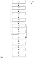
- FIG 2 shows a flowchart of an exemplary method 200 for controlling a cleaning robot 100.
- the cleaning robot 100 is at a starting position on the surface 105.
- the starting position can be chosen arbitrarily and the cleaning robot 100 can, for example, by an operator at the starting position the area 105 can be placed and activated.
- the cleaning robot 100 can drive straight ahead in any direction on the surface 105 until, in a step 215, it detects an obstacle that interferes with its further travel.
- the cleaning robot 100 can be stopped and in a step 220 an obstacle position can be determined at which the cleaning robot 100 or the detected obstacle is located. It is preferable that a direction in which the obstacle extends with respect to the cleaning robot 100 is additionally determined.
- a step 225 it can be checked whether sufficient obstacle positions have been determined in order to determine boundaries of the area 105 with a predetermined accuracy or reliability. If this is not the case, the cleaning robot 100 can change its direction by a predetermined angle in a step 230 can be in particular 90°, and the method 200 can continue in step 210, so that the steps 210 to 225 are run through again.
- boundaries of the area 105 can be determined.
- the boundaries can be formed, for example, by connecting previously determined obstacle positions with one another.
- a predetermined shape of the surface 105 can be determined or assumed. In one embodiment, the shape may be determined based on the determined obstruction positions before the boundaries of the area 105 are determined. Different shapes may typify different pieces of furniture 110 that may include a surface 105 to be cleaned. A type of a present piece of furniture 110 can exist, for example, in the form of an external specification or can be determined on the part of the cleaning robot 100 on the basis of specific obstacle positions or a specific form of delimitations of the area 105 .
- the cleaning robot 100 can be moved to a predetermined position, wherein the position can be defined depending on the specific shape, the specific piece of furniture 110 or an external specification. Subsequently, by means of the dispensing device 130 bait for mites can be dispensed onto the surface 105 .
- a step 245 at least a predetermined time preferably elapses during which the mites are attracted by the bait that is dispensed.
- the cleaning robot 100 can, for example, move to a further position on the surface 105 and output further lures there.
- he can use the cleaning device 125 to process an area of the surface 105 on which no bait has been dispensed.
- the cleaning robot 100 can return to the position from step 240 in a step 250 and pick up mites or other foreign objects in the vicinity of the position. For this he can use the fan 145 in particular to suck off the surface 105 in this area. Excess attractant and other loose particles such as dust or dirt particles can also be sucked in. Has been used at different positions on the attractant Surface 105 is applied, the surface 105 can be cleaned in all positions by means of the blower 145.
- the entire area 105 may be cleaned to pick up the mites, excess attractant and other debris at the location or locations.
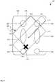
- figure 3 shows an exemplary path 305 of a cleaning robot 100 over a padded surface 105.
- the surface 105 is assumed to be a surface of a piece of furniture 110 that can be used as a double bed.
- the path 305 begins at a starting position 310, which may be chosen at random. An alignment of the cleaning robot 100 at the starting position 310 can also be random. From there, the path 305 runs straight ahead in the selected direction until an obstacle position 315 has been detected, which indicates a boundary of the area 105 .
- the cleaning robot 100 changes its course there by a predetermined angle 320, which in the present example is 90° clockwise. If an obstacle is unidirectional at obstacle location 315, the course can be altered to point in a direction away from the obstacle. The cleaning robot 100 can then drive straight ahead again until it reaches another obstacle position 315 .
- the boundaries of the area 105 can be determined. In particular, when a number of detected obstacle positions 315 is sufficiently large or when there is a smaller than a predetermined distance between adjacent obstacle positions 315, the boundaries of the area 105 can be determined with sufficient certainty or accuracy. If the distance between the obstacle positions 315 is very different, a suspected obstacle position 315 can be specifically searched for, for example in an area between certain obstacle positions 315.
- the surface 105 can be recognized as the surface of a double bed based on its size, its shape or a ratio of side lengths.
- This area 105 can be assigned one or more areas where an increased occurrence of mites can be expected. In the chosen example, this can include two header areas 325, two body areas 330 and/or three footer areas 335.
- the areas 325 to 335 may be determined by where certain portions of a person typically are when using the furniture item 110 that includes the surface 105 .
- the cleaning robot 100 can then start controlling mites in one or more of the areas 325 to 335 . For this purpose, in particular attractant for mites can be applied at a position in one of the areas 325 to 335 or on a section of one of the areas 325 to 335 and sucked off again later.
- an area where attractant is deployed may be determined based on different or additional criteria.
- the area can be determined in such a way that it maintains a predetermined distance from an obstacle, in particular a boundary of the area 105 .
- a shape of the area can be selected such that the area can be completely swept over by the cleaning robot 100 as easily as possible with simple driving maneuvers.
- a simple driving maneuver may involve driving straight forward or backward.
- a time-consuming turning of the cleaning robot 100 about its vertical axis can be minimized. In this way, the area can be cleaned quickly before mites that have been attracted can be withdrawn again by sound or vibrations of the cleaning robot 100 .
- the area can be selected in such a way that as large a part of it as possible can easily be driven over, ie preferably has no obstacles and more preferably can be driven over quickly.
- the area can be selected in such a way that a surface of the area 105 in the area is as well suited as possible for applying bait and/or for cleaning.
- the surface 105 can be as flat as possible in the area and, if possible, have no cracks or folds.
- Cleaning the surface 105 after the waiting time can affect the entire surface 105 or only part of it. If the bait has only been applied in a predetermined area, the cleaning can only take place in this area or in an area that only slightly overlaps.
- steps 210 to 230 in particular can be omitted or replaced by another heuristic.
- the boundaries of the area 105 can in step 235, for example by means of a navigation device the basis of a map of the surroundings or due to a past inspection of the area 105 already be known.
- the cleaning robot may be moved in a predetermined manner over the surface 105 to improve a concentration of mites in the attractant provided area.
Landscapes
- Life Sciences & Earth Sciences (AREA)
- Pest Control & Pesticides (AREA)
- Engineering & Computer Science (AREA)
- Environmental Sciences (AREA)
- Wood Science & Technology (AREA)
- Zoology (AREA)
- Insects & Arthropods (AREA)
- Physics & Mathematics (AREA)
- Plasma & Fusion (AREA)
- Food Science & Technology (AREA)
- Soil Sciences (AREA)
- Electric Vacuum Cleaner (AREA)
- Catching Or Destruction (AREA)
- Control Of Position, Course, Altitude, Or Attitude Of Moving Bodies (AREA)
Abstract
Description
- Die Erfindung betrifft ein Verfahren zum Steuern eines Reinigungsroboters mit einer Reinigungseinrichtung über eine Fläche. Insbesondere betrifft die Erfindung ein Verfahren zur Ausgaben von einem Lockmittel für Milben.
- In einem Haushalt befinden sich eines oder mehrere gepolsterte Möbelstücke, wie beispielsweise ein Sofa, ein Sessel oder ein Bett. Zur Wahrung der Hygiene im Haushalt ist es üblich, gepolsterte Flächen der Möbelstücke regelmäßig zu reinigen. Bei einer üblichen Reinigung mittels Absaugens können jedoch Kleinlebewesen, die sich in einer Polsterfläche eingenistet haben, insbesondere Milben, oft nicht adäquat entfernt werden. Die sich überwiegend von Hautschuppen ernährenden Milben stellen zwar an sich keine Gefahr für einen Menschen dar, jedoch sind ihre Ausscheidungen hochgradig allergen, sodass die Gefahr besteht, dass ein Benutzer eines solchen Polstermöbels unter allergischen Beschwerden leidet.
- Es wurde vorgeschlagen, Milben mittels einer starken Lampe zur Aussendung von ultraviolettem Licht zu bekämpfen. Das UV-Licht kann mittels eines autonomen Roboters beim Abfahren der Fläche ausgesandt werden. Solches kurzwellige Licht kann jedoch schädlich sein, wenn es in die Augen eines Menschen oder eines Haustiers gerät und Reizungen oder Hautirritationen bereits dann hervorrufen, wenn es über längere Zeit auf ungeschützte Haut fällt. Es wurde auch vorgeschlagen, zur Bekämpfung von Milben ein nichtthermisches Plasma zu verwenden. Dieses kann jedoch Ozon freisetzen, das bereits in geringen Konzentrationen für gesundheitlich vorbelastete Personen ein Reizklima bewirken kann. Außerdem kann eine flächendeckende Behandlung einer Oberfläche eines Polstermöbels mit ultraviolettem Licht oder mit Plasma energieaufwendig oder langwierig sein. Ein Roboter kann viel Energie zur Reinigung eines größeren Polstermöbels wie beispielsweise eines Doppelbetts erfordern, sodass er einen großen Energiespeicher benötigen kann. Ein kleinerer Energiespeicher muss unter Umständen vor Beenden der Reinigung nachgeladen werden, sodass die Reinigung insgesamt sehr lange dauern kann.
- Eine der vorliegenden Erfindung zu Grunde liegende Aufgabe besteht in der Angabe einer verbesserten Technik zur autonomen Reinigung einer gepolsterten Fläche. Die Erfindung löst diese Aufgabe mittels der Gegenstände der unabhängigen Ansprüche. Unteransprüche geben bevorzugte Ausführungsformen wieder.
- Das erfindungsgemäße Verfahren zum Steuern eines Reinigungsroboters eignet sich insbesondere, um mittels eines wie folgt beschriebenen Reinigungsroboter ausgeführt zu werden. Ein Reinigungsroboter umfasst für eine gepolsterte Fläche eine Antriebseinrichtung; eine Steuereinrichtung zur Führung des Reinigungsroboters über die zu reinigende Fläche; eine Reinigungseinrichtung, die dazu eingerichtet ist, Milben im Bereich der Fläche zu bekämpfen; und eine Ausgabevorrichtung für ein Lockmittel für Milben. Dabei ist die Steuereinrichtung dazu eingerichtet, Lockmittel auf der Fläche auszugeben und nach einer vorbestimmten Wartezeit die Reinigungseinrichtung im Bereich des ausgegebenen Lockmittels zu aktivieren. Das Bekämpfen kann ein Aufnehmen und/oder ein Deaktivieren oder Zerstören von Milben umfassen.
- Die gepolsterte Fläche kann insbesondere ein Sitz- oder Liegemöbel wie einen Sessel, eine Couch, einen Stuhl oder ein Bett umfassen. Die gepolsterte Fläche kann auch einen Boden bedecken und etwa einen Teppich oder einen Teppichboden umfassen. Die Fläche liegt bevorzugt in einem Haushalt vor, insbesondere einem Privathaushalt.
- Es wurde erkannt, dass ein flächendeckendes Reinigen der Fläche vermieden werden kann, indem die Milben an eine vorbestimmte Position gelockt und dort gezielt aufgenommen bzw. bekämpft werden. Ein Energieaufwand zum Bewegen des Reinigungsroboters oder zum Betreiben der Reinigungseinrichtung kann verringert sein. Der Reinigungsroboter kann einen verkleinerten Energiespeicher aufweisen, sodass er insgesamt kleiner oder leichter konstruiert werden kann. Ein Reinigungsvorgang kann schneller abgeschlossen sein.
- Das Bekämpfen kann ein Inaktivieren von Milben umfassen. Beim Inaktivieren kann eine Milbe so behandelt werden, dass ihre Schadwirkung möglichst minimiert ist. Die Schadwirkung einer Milbe kann in ihrer Verbreitung von Ausscheidungen, die allergen wirken können, insbesondere Kot, auf der Fläche bestehen. Das Inaktivieren kann eine Milbe bewegungsunfähig machen, sodass ihre Schadwirkung auf der Fläche stark eingeschränkt ist. Daneben kann das Inaktivieren die Milbe so weit schädigen, dass sie keinen nennenswerten Stoffwechsel mehr betreibt. Insbesondere kann eine Ausscheidung von Exkrementen unterbunden sein. Das Inaktivieren kann auch ein Abtöten umfassen.
- Die Reinigungseinrichtung ist bevorzugt dazu eingerichtet ist, Milben von der Fläche zu entfernen. Eine inaktivierte Milbe kann sich nicht mehr aktiv auf der Fläche halten, sodass sie verbessert entfernt werden kann. Von der Fläche entfernte Milben und/oder Schmutz können in einem Behälter gesammelt werden. Dazu können Feststoffe von einer an der Fläche abgesaugten Luft abgeschieden werden, beispielsweise durch einen Tiefenfilter oder einen Zyklonfilter. Durch das vorausgehende Inaktivieren kann verhindert werden, dass Milben aus dem Behälter entkommen.
- Das Entfernen von Milben kann auf einem Teil der Fläche erfolgen, auf dem zuvor Lockmittel ausgebracht wurde. In einer Ausführungsform kann das Entfernen auf einem Teil der Fläche, auf dem zuvor kein Lockmittel ausgebracht wurde, unterbleiben. Eine Einrichtung zum Ausbringen von Lockmittel kann eine vorbestimmte Bearbeitungsbreite aufweisen, und eine Einrichtung zur Bekämpfung und insbesondere Inaktivierung kann eine entsprechende Bearbeitungsbreite aufweisen. Das Entfernen der Milben kann ebenfalls auf einer entsprechenden Bearbeitungsbreite erfolgen. Durch zueinander korrespondierende Bearbeitungsbreiten kann die Fläche effizienter gereinigt werden. Ein Aufwand zur Bewegung des Reinigungsroboters über die Fläche kann minimiert sein.
- Das Lockmittel ist bevorzugt dazu eingerichtet, die Milben nicht zu schädigen. Das Lockmittel kann insbesondere nicht toxisch für Milben sein. Dadurch muss nicht gewartet werden, bis eine inaktivierende Wirkung des Lockmittels eingetreten ist. Außerdem kann es einfacher sein, ein reines Lockmittel bereitzustellen, als ein Lockmittel mit schädigender Wirkung. Das Inaktivieren der Milben erfolgt bevorzugt mittels einer elektromechanischen Einrichtung, die beispielsweise ein nichtthermisches Plasma bereitstellen kann, wie unten genauer ausgeführt ist.
- Die Steuereinrichtung ist bevorzugt dazu eingerichtet, eine Emission von Schall oder Vibrationen durch den Reinigungsroboter während der Wartezeit zu minimieren, idealerweise ganz zu unterdrücken. Das Anlocken von Milben kann dadurch unterstützt werden. Durch das Ausbleiben von Schallwellen oder Vibrationen, die eine Milbe dazu bringen können, sich nicht zu bewegen, sich zu verstecken, sich festzuhalten oder zu fliehen, können die Milben effektiver angelockt werden. Eine größere Anzahl Milben kann angelockt werden oder eine erforderliche Wartezeit zum Anlocken der Milben kann verkürzt sein.
- Es ist besonders bevorzugt, dass die Steuereinrichtung dazu eingerichtet ist, das Lockmittel an einer vorbestimmten Stelle der gepolsterten Fläche auszugeben. Die Stelle kann insbesondere in Abhängigkeit einer Art der gepolsterten Fläche bestimmt sein. Ist die Fläche beispielsweise Bestandteil eines Stuhls oder eines Sessels, so kann die Position in einem Bereich liegen, auf dem üblicherweise Oberschenkel einer darauf sitzenden Person ruhen. Ist die Fläche Bestandteil eines Bettes, so kann die Position beispielsweise in einem Kopfbereich, einem Rumpfbereich oder einem Fußbereich einer im Bett liegenden Person liegen. Anderen gepolsterten Flächen können entsprechende Bereiche oder Positionen zugeordnet sein. So können Milben insbesondere dort bekämpft werden, wo sie mit gesteigerter Wahrscheinlichkeit oder in gesteigerter Anzahl auftreten. Die Bekämpfung der Milben kann so effizienter sein.
- Es ist insbesondere bevorzugt, dass die Reinigungseinrichtung dazu eingerichtet ist, ein nichtthermisches Plasma bereitzustellen. Das Plasma kann derart bereitgestellt werden, dass Milben bekämpft und bevorzugt inaktiviert werden. Ein nichtthermisches Plasma (auch: kaltes atmosphärisches Plasma oder Niedertemperaturplasma, NTP) ist ein Plasma, das sich nicht im thermischen Gleichgewicht befindet, in welchem sich also z. B. die Temperaturen enthaltener Teilchensorten (Neutralteilchen, Ionen, Elektronen) signifikant unterscheiden. Ein kaltes atmosphärisches Plasma erzeugt eine reaktive Mischung aus Plasmakomponenten wie Elektronen, Ionen, angeregten Atomen und Molekülen, reaktiven Spezies (wie z.B. O3, NO, NO2, etc.), UV-Strahlung und Wärme. Mittels dieser Mischung können Bakterien, Pilze, Viren, Sporen oder Geruchsmoleküle effektiv zerstört werden. Mittels NTP können bei einer Temperatur von unter 100° C zeitsparend Erreger sogar durch Kleidung oder Bettwäsche hindurch abgetötet werden. Auch kleine vielzellige Lebewesen wie Milben können mittels NTP abgetötet werden. Ein großer Vorteil des nichtthermischen Plasmas ist, dass es ungefähr Zimmertemperatur besitzt und bei Atmosphärendruck auf der Erde produziert werden kann. Zur Herstellung eines NTP kann ein Gas teilweise ironisiert werden, sodass nur ca. ein Teilchen aus 109 ionisiert ist. Je nach verwendeter Plasmaquelle können Anteile umfasster Plasmakomponenten variieren oder auch gezielt verändert werden. So kann eine Konzentration oder Zusammensetzung von Plasmakomponenten an eine anvisierte Anwendung angepasst werden.
- Das Plasma kann effizient gegen Milben eingesetzt werden, ohne eine Gesundheitsbelastung einer Person im Bereich der Fläche zu riskieren. Gleichzeitig kann mittels des Plasmas eine Desinfektion der Fläche erfolgen.
- Es ist insbesondere bevorzugt, dass die Reinigungseinrichtung eine nichtthermische Plasmaquelle umfasst, die auf der Basis von Oberflächen-Mikroentladungen arbeitet. Eine solche Plasmaquelle ist beispielsweise in
EP 3 326 436 A1 dargestellt. Derartige Plasmaquellen können mit einer relativ geringen elektrischen Spannung auskommen und energiesparend arbeiten, sodass sie sich für einen Batteriebetrieb eignen. Die Größe einer Elektrode, an der das Plasma bereitgestellt wird, kann in weiten Grenzen variiert werden. Die Elektrode selbst kann flach und flexibel ausgeführt werden. In einer weiteren Ausführungsform ist auch eine alternative Technologie zur Bereitstellung eines nichtthermischen Plasmas anwendbar, beispielsweise eine magnetisch organisierte Plasmaschichttechnologie, eine Mikrowellen-Plasmatechnologie oder eine Venturi-Plasmatechnologie. - Der Reinigungsroboter umfasst weiter bevorzugt ein Gebläse zur Absaugung von Luft aus dem Bereich der Fläche. Das Gebläse kann insbesondere von einem Saugwerk umfasst sein, wie es von einem Staubsaugroboter bekannt ist. Mittels des Gebläses können die Milben im Bereich der Fläche aufgenommen werden. Bevorzugt werden die aufgenommenen Milben, eventuell verbleibendes Lockmittel und/oder zusätzlich aufgenommene Schmutzpartikel aus der eingesogenen Luft abgeschieden und in einem Behälter aufgenommen. Die gepolsterte Fläche kann dadurch verbessert gereinigt werden.
- Optional kann eine Einrichtung zum Lösen von Objekten von der Fläche vorgesehen sein, beispielsweise eine Bürste oder ein Besen. Die Einrichtung kann beweglich sein, um vom Reinigungsroboter gegenüber der Fläche bewegt zu werden. Schmutz, Partikel oder Milben können so verbessert von der Fläche gelöst werden. Insbesondere wenn die Fläche ein Textil umfasst, kann dieses durch die Einrichtung verbessert gereinigt werden. die Einrichtung kann oszillierend oder rotierend angetrieben werden und beispielsweise als Bürsten- oder Borstenwalze realisiert sein.
- In einer weiteren Ausführungsform umfasst der Reinigungsroboter zusätzlich einen Filter für die abgesaugte Luft. Es können unterschiedliche Filter für unterschiedliche Zwecke vorgesehen sein. Beispielsweise kann ein erster Filter zur Rückhaltung von Staub, Schmutzpartikeln oder aufgenommenen Milben vorgesehen sein. Ein derartiger Filter kann insbesondere als Vliesfilter, Porenfilter oder Zyklonfilter ausgebildet sein. Dieser oder ein zweiter Filter kann zum Rückhalten von Ozon aus der abgesaugten Luft eingerichtet sein und beispielsweise einen Aktivkohlefilter umfassen. Ozon, das bei der Bereitstellung von kaltem Plasma an der Reinigungseinrichtung gebildet werden kann, kann so davon abgehalten werden, sich im Bereich der gepolsterten Fläche auszubreiten und von einer Person aufgenommen zu werden.
- Der Reinigungsroboter ist bevorzugt zum autonomen Betrieb auf der gepolsterten Fläche eingerichtet. Dazu kann der Reinigungsroboter eine spezielle Antriebseinrichtung umfassen, um zu verhindern, dass er beispielsweise in einem sehr weichen Polster einsinkt und manövrierunfähig wird. Es wird vorgeschlagen, dass die Antriebseinrichtung wenigstens eines, bevorzugt aber zwei parallele Kettenlaufwerke umfasst. Das Kettenlaufwerk kann eine Gleiskette, ein Antriebsrad, ein Führungsrad und zwei oder mehr Laufrollen umfassen. Durch ihre große Auflagefläche auf der gepolsterten Fläche kann die Gleiskette nur einen geringen spezifischen Bodendruck bewirken, sodass der Reinigungsroboter auch auf sehr weichen oder glatten Flächen manövrierfähig bleiben kann.
- Es ist weiter bevorzugt, dass der Reinigungsroboter wenigstens einen Sensor zur Bestimmung einer Begrenzung der Fläche aufweist. Dabei können unterschiedliche Begrenzungen unterschieden werden, insbesondere eine Stufe, die sich von der Fläche aus nach unten erstreckt, und eine Schwelle, die sich nach oben erstreckt. Eine Stufe kann beispielsweise am Ende einer Matratze gebildet sein. Eine Schwelle kann etwa durch ein Fußteil oder ein Haupt eines Bettes gebildet sein, in dem eine Matratze liegt, deren Oberfläche bearbeitet werden kann.
- Nach einem Aspekt der vorliegenden Erfindung umfasst ein Verfahren zum Steuern eines Reinigungsroboters mit einer Reinigungseinrichtung über eine Fläche Schritte des Fahrens des Reinigungsroboters geradeaus bis zum Erreichen eines Hindernisses und des Bestimmens einer Hindernisposition; des Änderns der Fahrtrichtung um einen vorbestimmten Winkel und des Wiederholens des vorangehenden Schritts sooft, bis ausreichend viele Hindernispositionen bestimmt wurden, um Begrenzungen der Fläche zu bestimmen; und des Führens des Reinigungsroboters auf der Fläche in Abhängigkeit ihrer bestimmten Begrenzungen.
- Das Verfahren eignet sich insbesondere, um mittels eines hierin beschriebenen Reinigungsroboter ausgeführt zu werden. Eine Steuereinrichtung des Reinigungsroboters kann eine Verarbeitungseinrichtung umfassen, die dazu eingerichtet ist, ein hierin beschriebenes Verfahren ganz oder teilweise auszuführen. Dazu kann die Verarbeitungseinrichtung einen programmierbaren Mikrocomputer oder Mikrocontroller umfassen und das Verfahren kann in Form eines Computerprogrammprodukts mit Programmcodemitteln vorliegen. Das Computerprogrammprodukt kann auch auf einem computerlesbaren Datenträger abgespeichert sein. Merkmale oder Vorteile des Verfahrens können auf die Steuereinrichtung bzw. den Reinigungsroboter übertragen werden und umgekehrt.
- Es ist besonders bevorzugt, dass auf einem Bereich oder an einer Position auf der Fläche ein Lockmittel für Milben ausgegeben wird; und dass nach einer vorbestimmten Wartezeit nach dem Ausgeben eine Reinigungseinrichtung des Reinigungsroboters im Bereich des ausgegebenen Lockmittels aktiviert wird. Die Position oder der Bereich kann auf der Basis eines hierin beschriebenen Bestimmungsverfahrens für Begrenzungen der Fläche oder auf andere Weise bestimmt werden. Es ist weiter bevorzugt, dass der Reinigungsroboter während der Wartezeit von der Position weggefahren wird. Beispielsweise kann Lockmittel nacheinander an mehreren Positionen ausgegeben und später mittels der Reinigungseinrichtung wieder entfernt werden. Außerdem kann der Reinigungsroboter während der Wartezeit einen restlichen Bereich der zu reinigenden Fläche befahren und insbesondere mittels der Reinigungseinrichtung behandeln.
- Die Wartezeit liegt zwischen dem Ausbringen des Lockmittels und dem Bekämpfen der Milben. Das Bekämpfen kann ein Inaktivieren, optional ein Abtöten, sowie weiter optional ein Entfernen, insbesondere ein Absaugen umfassen, wie hierin genauer beschrieben ist. Das Inaktivieren oder Abtöten erfolgt bevorzugt mittels eines nichtthermischen Plasmas.
- Der Reinigungsroboter kann nach dem Ausbringen von Lockmittel und vor dem Reinigen der Fläche eine vorbestimmte Bewegung ausführen, um Milben verbessert auf eine Inaktivierung und/oder Entfernung vorzubereiten.
- Milben können eine begrenzte Mobilität aufweisen. Sie können von dem Lockmittel angelockt und/oder von Schall oder Vibrationen verschreckt werden. Der Reinigungsroboter kann die bei seiner Bewegung unvermeidlichen Vibrationen oder Geräusche dazu einsetzen, die Milben zu dem Bereich zu treiben, in dem das Lockmittel ausgebracht wurde, oder um sie in dem Bereich zu konzentrieren. Beispielsweise kann der Reinigungsroboter den Bereich umfahren, optional auch mehrfach und mit sinkendem Abstand, beispielsweise spiralförmig. Die Bewegung kann bis in den Bereich hinein fortgesetzt werden, um die Milben idealerweise an einer vorbestimmten Position im Bereich zu sammeln.
- Der Reinigungsroboter kann nach dem Ausbringen des Lockmittels in dem Bereich ferner dazu gesteuert werden, einen umliegenden Bereich zu reinigen, insbesondere mittels Absaugen. Dadurch kann eine Feuchtigkeit im umliegenden Bereich reduziert werden, sodass der nicht abgesaugte Bereich für Milben attraktiver als der getrocknete umliegende Bereich ist. Eine Konzentration der Milben in dem mit Lockmittel versehenen Bereich kann dadurch weiter verbessert werden. Das Reinigen des umliegenden Bereichs kann zusammen mit dem systematischen Treiben von Milben in Richtung des mit Lockmittel versehenen Bereichs erfolgen.
- Vor und/oder nach der vorbestimmten Bewegung kann der Reinigungsroboter während einer vorbestimmten Wartezeit in einen ruhigen Modus versetzt werden, in welchem er möglichst geringe oder gar keine Vibrationen und/oder Schall emittiert, um die Milben nicht aus dem Bereich zu verscheuchen. Schließlich können die Milben mittels der Reinigungsvorrichtung inaktiviert und/oder entfernt werden.
- Es ist weiter bevorzugt, dass die Position, an der das Lockmittel ausgegeben wird, auf der Basis von Begrenzungen der Fläche bestimmt wird. Bezüglich der Begrenzungen kann ein Bereich vorgegeben sein, in dem die Position liegt. Der Bereich kann auch auf der Basis einer Art eines Möbelstücks bestimmt werden, von dem die gepolsterte Fläche umfasst ist. Beispielhafte Arten von Möbelstücken umfassen ein Bett, einen Sessel, einen Stuhl, einen Hocker und ein Sofa. Die Art des Möbelstücks kann auf der Basis von Begrenzungen der Fläche bestimmt werden. Beispielsweise kann eine halbrunde Fläche einer vorbestimmten Größe auf die Sitzfläche eines Sessels hinweisen, während eine langgestreckte, rechteckige Fläche einer anderen Größe auf die Sitzfläche einer Couch oder auf ein Bett hinweisen kann.
- In einer weiter bevorzugten Ausführungsform ist die Fläche rechteckig, wobei der Winkel ca. 90° beträgt. Begrenzungen der Fläche können bereits in wenigen Zügen ausreichend genau bestimmt werden. Bevorzugt wird immer der gleiche Winkel verwendet; eine Verwendung unterschiedlicher Winkel ist jedoch ebenfalls vorstellbar. Der Winkel kann in einer Ausführungsform jeweils in einem Bereich zwischen ca. 45° und ca. 135° liegen. Insbesondere können vier Hindernispositionen bestimmt werden. Es wurde erkannt, dass bereits vier Hindernispositionen ausreichen können, um Begrenzungen der Fläche zu bestimmen. Zur Erhöhung einer Bestimmungssicherheit können auch mehr Hindernispositionen bestimmt werden.
- Es ist weiterhin bevorzugt, dass eine Richtung bestimmt wird, in der sich ein Hindernis erstreckt; wobei die Begrenzungen zusätzlich auf der Basis einer Richtung eines Hindernisses bestimmt werden. Diese Vorgehensweise kann insbesondere an einer rechteckigen Fläche erfolgreich sein, wo das Hindernis eine Kante, eine Stufe oder eine Schwelle bilden kann.
- Es ist weiterhin bevorzugt, dass unterschiedliche Arten von Hindernissen erkannt werden. Eine erste Art Hindernis kann erkannt werden, wenn der Reinigungsroboter an eine Schwelle in der Fläche fährt. Eine zweite Art Hindernis kann erkannt werden, wenn der Reinigungsroboter an eine Stufe in der Fläche fährt. Anhand der Art der Hindernisse kann eine Art eines Möbelstücks bestimmt werden, von dem die gepolsterte Fläche umfasst ist. Beispielsweise kann ein Bett eine rechteckige Polsterfläche umfassen, die an allen vier Seiten durch eine Schwelle oder eine Stufe begrenzt ist. Eine Couch kann eine ähnlich geformte Fläche aufweisen, ist jedoch üblicherweise an wenigstens einer Längsseite durch eine Schwelle begrenzt, beispielsweise in Form einer Rückenlehne oder einer Armlehne.
- Die Erfindung wird nun unter Bezug auf die beiliegenden Figuren genauer beschrieben, in denen:
- Figur 1
- einen Reinigungsroboter;
- Figur 2
- ein Ablaufdiagramm eines Verfahrens zum Steuern eines Reinigungsroboters; und
- Figur 3
- einen beispielhaften Pfad eines Reinigungsroboters über eine gepolsterte Fläche
-
Figur 1 zeigt eine schematische Darstellung eines beispielhaften Reinigungsroboters 100, der dazu eingerichtet ist, eine Fläche 105 zu reinigen. Die Fläche 105 ist bevorzugt gepolstert und weiter bevorzugt von einem Möbelstück 110 umfasst. Das Möbelstück 110 kann dazu eingerichtet sein, eine Person insbesondere sitzend oder liegend aufzunehmen. Das Möbelstück 110 kann daher insbesondere ein Bett, ein Sofa, einen Sessel, einen Schemel oder Hocker oder einen Stuhl umfassen. In einer weiteren Ausführungsform kann die Fläche 105 auch im Wesentlichen flach auf dem Boden liegen, beispielsweise in Gestalt eines Teppichs. Der Reinigungsroboter 100 umfasst bevorzugt eine Antriebseinrichtung 115, eine Steuereinrichtung 120, eine Reinigungseinrichtung 125 und eine Ausgabevorrichtung 130. - Der Reinigungsroboter 100 ist beispielhaft rund nach der Art eines Diskus ausgebildet, kann jedoch auch anders geformt sein. Bevorzugt ist der Reinigungsroboter 100 derart geformt, dass er selbsttätig unter ein Kissen oder eine Decke eintauchen kann, die auf der Fläche 105 liegen können. Die Antriebseinrichtung 115 kann einen konventionellen Antrieb mit zwei oder mehr angetriebenen Rädern und optional einem oder mehreren gelenkten Rädern umfassen. In der dargestellten Ausführungsform umfasst die Antriebseinrichtung 115 zwei Kettenlaufwerke, die rechts und links einer Längsachse des Reinigungsroboters 100 angeordnet sind. Jedes Kettenlaufwerk 115 umfasst bevorzugt einen Antriebsmotor 135 und weiter bevorzugt einen Drehsensor 140 zur Bestimmung eines mit dem jeweiligen Kettenlaufwerk 115 zurückgelegten Wegs.
- Die Reinigungseinrichtung 125 ist dazu eingerichtet, kleine Gegenstände von der Fläche 105 aufzunehmen und umfasst bevorzugt ein Gebläse 145, das von einem Saugwerk umfasst sein kann. Die Gegenstände können aufgenommen werden, indem Luft nahe an der Fläche 105 eingesogen wird, sodass die Gegenstände im Luftsog mitgerissen werden. Abgesaugte Luft kann in einem Filter 150 gefiltert werden. Ein erster Filter 150 kann mechanisch sein, um beispielsweise Staub, Milben oder Schmutzpartikel abzuscheiden. Ein zweiter Filter 150 kann chemisch ausgeführt sein, beispielsweise um Ozon abzuscheiden bzw. umzuwandeln. Der zweite Filter 150 ist bevorzugt in Form eines Aktivkohlefilters ausgeführt, dessen Kohlenstoff mit Ozon zu Kohlenstoffdioxid oxidiert werden kann. Das Ozon kann im Bereich der Fläche 105 gebildet werden, wenn eine von der Reinigungseinrichtung 125 umfasste Plasmaquelle 155 in Betrieb ist.
- Die Plasmaquelle 155 ist bevorzugt dazu eingerichtet, ein nichtthermisches Plasma bereitzustellen und arbeitet weiter bevorzugt nach dem Prinzip der Oberflächen-Mikroentladungstechnologie. Anstelle der Plasmaquelle 155 kann auch eine andere Einrichtung zum Abtöten von Milben vorgesehen sein. Die Vorrichtung wird bevorzugt elektrisch betrieben und kann beispielsweise eine Quelle für ultraviolettes Licht umfassen. Die Ausgabevorrichtung 130 umfasst bevorzugt einen Vorratsbehälter für Lockmittel und eine Dosiereinrichtung zum Ausbringen einer steuerbaren Menge des Lockmittels auf die Fläche 105. Das Lockmittel ist bevorzugt pulverförmig, kann jedoch auch beispielsweise in flüssiger Form vorliegen. In einer Ausführungsform umfasst das Lockmittel Kieselgur.
- Zur Kollisionsvermeidung, Orientierung oder Navigation können zusätzliche Sensoren vorgesehen sein. Ein Inertialsensor 160 kann einen Beschleunigungssensor und/oder einen Drehratensensor umfassen. Beide Arten von Sensoren arbeiten bevorzugt mehrdimensional und insbesondere in jeweils drei Raumrichtungen. Einer oder mehrere Nahfeldsensoren 165 können zur Abtastung eines Bereichs von ca. 0 bis 10 Zentimetern vor dem Reinigungsroboter 100 vorgesehen sein. Ein Nahfeldsensor 165 kann insbesondere dazu eingerichtet sein, eine Schwelle zu erkennen, also ein Hindernis, das von der Fläche 105 in vertikaler Richtung mehr als ein vorbestimmtes Maß aufragt. Das vorbestimmte Maß kann einige Zentimeter betragen, beispielsweise ca. 1 bis ca. 3 Zentimeter.
- Ferner können einer oder mehrere Bodensensoren 170 vorgesehen sein, die jeweils dazu eingerichtet sind, eine Stufe unter dem Reinigungsroboter 100 zu erkennen. Eine Stufe erstreckt sich vertikal nach unten und hat üblicherweise eine bestimmte Mindesthöhe, beispielsweise einige Zentimeter oder Dezimeter. Eine Stufe kann auch mittels eines Neigungssensors bestimmt werden, der bestimmt, wenn sich der Reinigungsroboter 100 um mehr als ein vorbestimmtes Maß neigt, insbesondere in Fahrtrichtung. Zur Versorgung von Komponenten des Reinigungsroboters 100 mit Energie ist bevorzugt ein elektrischer Energiespeicher 175 vorgesehen. Damit kann der Reinigungsroboter 100 unabhängig von einem Energienetz betrieben werden.
- Der Reinigungsroboter 100 kann über weitere Komponenten verfügen, die an einem Gerät des Standes der Technik bekannt sind, etwa eine Kommunikationseinrichtung oder eine Ausgabevorrichtung 130 in beispielsweise optischer, haptischer oder akustischer Weise. Zusätzliche Sensoren können einen oder mehrere Fernbereichssensoren umfassen, die insbesondere als Kamera, Radarsensor, LiDAR-Sensor oder Tiefenkamera ausgebildet sein können. Zum Betrieb einer Kamera kann außerdem eine Beleuchtungseinrichtung vorgesehen sein.
- Es wird vorgeschlagen, dass der Reinigungsroboter 100 dazu eingerichtet ist, die Fläche 105 autonom von Milben zu reinigen. Dazu kann der Reinigungsroboter 100 zunächst bestimmte Eigenschaften der Fläche 105 bestimmen, um dann mittels der Ausgabevorrichtung 130 ein Lockmittel für Milben an einer vorbestimmten Position auf der Fläche 105 auszubringen und nach einer vorbestimmten Zeit mittels der Reinigungseinrichtung 125 wieder aufzunehmen. Vor oder nach dem Aufnehmen können die Milben mittels der Plasmaquelle 155 abgetötet werden.
-
Figur 2 zeigt ein Ablaufdiagramm eines beispielhaften Verfahrens 200 zur Steuerung eines Reinigungsroboters 100. In einem ersten Schritt 205 befindet sich der Reinigungsroboter 100 an einer Startposition auf der Fläche 105. Die Startposition kann beliebig gewählt sein und der Reinigungsroboter 100 kann beispielsweise durch eine Bedienperson an der Startposition auf die Fläche 105 gelegt und aktiviert werden. - In einem Schritt 210 kann der Reinigungsroboter 100 in einer beliebigen Richtung auf der Fläche 105 geradeaus fahren, bis er in einem Schritt 215 ein Hindernis erfasst, das seine Weiterfahrt stört. Der Reinigungsroboter 100 kann angehalten werden und in einem Schritt 220 kann eine Hindernisposition bestimmt werden, an der sich der Reinigungsroboter 100 bzw. das erfasste Hindernis befindet. Es ist bevorzugt, dass zusätzlich eine Richtung bestimmt wird, in der sich das Hindernis bezüglich des Reinigungsroboters 100 erstreckt.
- In einem Schritt 225 kann überprüft werden, ob ausreichend Hindernispositionen bestimmt wurden, um Begrenzungen der Fläche 105 mit einer vorbestimmten Genauigkeit oder Zuverlässigkeit zu bestimmen. Ist dies nicht der Fall, so kann der Reinigungsroboter 100 in einem Schritt 230 seine Richtung um einen vorbestimmten Winkel ändern, der insbesondere 90° betragen kann, und das Verfahren 200 kann im Schritt 210 fortfahren, sodass die Schritte 210 bis 225 erneut durchlaufen werden.
- Insbesondere falls im Schritt 225 bestimmt wurde, dass ausreichend Hindernispositionen vorliegen, können in einem Schritt 235 Begrenzungen der Fläche 105 bestimmt werden. Die Begrenzungen können beispielsweise gebildet werden, indem zuvor bestimmte Hindernispositionen miteinander verbunden werden. Dabei kann eine vorbestimmte Form der Fläche 105 bestimmt oder vorausgesetzt werden. In einer Ausführungsform kann die Form auf der Basis der bestimmten Hindernispositionen bestimmt werden, bevor die Begrenzungen der Fläche 105 bestimmt werden. Unterschiedliche Formen können für unterschiedliche Möbelstücke 110 typisch sein, von denen eine zu reinigende Fläche 105 umfasst sein kann. Eine Art eines vorliegenden Möbelstücks 110 kann beispielsweise in Form einer externen Vorgabe vorliegen oder auf der Basis bestimmter Hindernispositionen bzw. einer bestimmten Form von Begrenzungen der Fläche 105 seitens des Reinigungsroboters 100 bestimmt werden.
- In einem Schritt 240 kann der Reinigungsroboter 100 an eine vorbestimmte Position bewegt werden, wobei die Position in Abhängigkeit der bestimmten Form, des bestimmten Möbelstücks 110 oder einer externen Vorgabe definiert sein kann. Anschließend kann mittels der Ausgabevorrichtung 130 Lockmittel für Milben auf die Fläche 105 ausgegeben werden.
- In einem Schritt 245 vergeht bevorzugt mindestens eine vorbestimmte Zeit, in der die Milben durch das ausgegebene Lockmittel angelockt werden. In dieser Zeit kann der Reinigungsroboter 100 beispielsweise eine weitere Position auf der Fläche 105 anfahren und dort weiteres Lockmittel ausgeben. Außerdem kann er mittels der Reinigungseinrichtung 125 einen Bereich der Fläche 105 bearbeiten, an dem kein Lockmittel ausgegeben wurde.
- Nach Ablauf der vorbestimmten Zeit kann der Reinigungsroboter 100 in einem Schritt 250 zu der Position vom Schritt 240 zurückkehren und Milben oder andere Fremdkörper im Bereich der Position aufnehmen. Dazu kann er insbesondere das Gebläse 145 verwenden, um die Fläche 105 in diesem Bereich abzusaugen. Überschüssiges Lockmittel und andere lose Partikel wie Staub oder Schmutzteilchen können dabei ebenfalls eingesaugt werden. Wurde Lockmittel an unterschiedlichen Positionen auf der Fläche 105 ausgebracht, so kann die Fläche 105 im Bereich aller Positionen mittels des Gebläses 145 gereinigt werden.
- In einer anderen Ausführungsform kann auch die gesamte Fläche 105 gereinigt werden, um die Milben, überschüssiges Lockmittel und andere Partikel an der oder den Positionen aufzunehmen.
-
Figur 3 zeigt einen beispielhaften Pfad 305 eines Reinigungsroboters 100 über eine gepolsterte Fläche 105. Beispielhaft sei die Fläche 105 eine Oberfläche eines Möbelstücks 110 angenommen, das als Doppelbett genutzt werden kann. - Der Pfad 305 beginnt an einer Startposition 310, die zufällig gewählt sein kann. Auch eine Ausrichtung des Reinigungsroboters 100 an der Startposition 310 kann zufällig sein. Von dort verläuft der Pfad 305 in der gewählten Richtung jeweils geradeaus, bis eine Hindernisposition 315 erfasst wurde, die auf eine Begrenzung der Fläche 105 hinweist. Der Reinigungsroboter 100 ändert dort seinen Kurs um einen vorbestimmten Winkel 320, der vorliegend beispielhaft 90° im Uhrzeigersinn beträgt. Verläuft ein Hindernis an der Hindernisposition 315 in einer Richtung, so kann der Kurs so geändert werden, dass er in eine vom Hindernis entfernte Richtung weist. Anschließend kann der Reinigungsroboter 100 wieder geradeaus fahren, bis er an eine weitere Hindernisposition 315 gelangt.
- Wurden ausreichend Hindernispositionen 315 erfasst, so können Begrenzungen der Fläche 105 bestimmt werden. Insbesondere wenn eine Anzahl von erfassten Hindernispositionen 315 ausreichend groß ist oder wenn zwischen benachbarten Hindernispositionen 315 jeweils ein kleinerer als ein vorbestimmter Abstand besteht, können die Begrenzungen der Fläche 105 mit ausreichender Sicherheit oder Genauigkeit bestimmt werden. Sind die Hindernispositionen 315 sehr unterschiedlich voneinander beabstandet, so kann eine vermutete Hindernisposition 315 gezielt gesucht werden, beispielsweise in einem Bereich zwischen bestimmten Hindernispositionen 315.
- Aufgrund ihrer Größe, ihrer Form oder eines Verhältnisses von Seitenlängen kann die Fläche 105 als Oberfläche eines Doppelbetts erkannt werden. Dieser Fläche 105 können einer oder mehrere Bereiche zugeordnet sein, an denen mit vermehrtem Aufkommen von Milben zu rechnen sein kann. Im gewählten Beispiel können dies zwei Kopfbereiche 325, zwei Rumpfbereiche 330 und/oder drei Fußbereiche 335 umfassen. Die Bereiche 325 bis 335 können danach bestimmt sein, wo sich bestimmte Abschnitte einer Person üblicherweise befinden, wenn diese das Möbelstück 110 benutzt, das die Fläche 105 umfasst. In einem oder mehreren der Bereiche 325 bis 335 kann der Reinigungsroboter 100 anschließend mit der Bekämpfung von Milben beginnen. Dazu kann insbesondere Lockmittel für Milben an einer Position in einem der Bereiche 325 bis 335 oder auf einem Abschnitt eines der Bereiche 325 bis 335 ausgebracht und später wieder abgesaugt werden.
- In einer weiteren Ausführungsform kann ein Bereich, in dem Lockmittel ausgebracht wird, auf der Basis anderer oder zusätzlicher Kriterien bestimmt werden. Der Bereich kann so bestimmt werden, dass er einen vorbestimmten Abstand zu einem Hindernis, insbesondere einer Begrenzung der Fläche 105, einhält. Ferner kann eine Form des Bereichs so gewählt werden, dass der Bereich mit einfachen Fahrmanövern durch den Reinigungsroboter 100 möglichst leicht vollständig überstrichen werden kann. Ein einfaches Fahrmanöver kann ein Geradeausfahren vorwärts oder rückwärts umfassen. Ein zeitraubendes Drehen des Reinigungsroboters 100 um seine Hochachse kann minimiert sein. So kann der Bereich zügig gereinigt werden, bevor sich angelockte Milben durch Schall oder Vibrationen des Reinigungsroboters 100 wieder zurückziehen können. Außerdem kann der Bereich so gewählt sein, dass ein möglichst großer Teil von ihm leicht überfahren werden kann, also bevorzugt keine Hindernisse aufweist und weiter bevorzugt zügig befahrbar ist. Der Bereich kann so gewählt sein, dass eine Oberfläche der Fläche 105 im Bereich möglichst gut zum Ausbringen von Lockmittel und/oder zum Reinigen geeignet ist. Dazu kann die Fläche 105 im Bereich möglichst eben sein und möglichst keine Ritzen oder Falten aufweisen.
- Ein Reinigen der Fläche 105 nach der Wartezeit kann die ganze Fläche 105 oder nur einen Teil davon betreffen. Wurde nur in einem vorbestimmten Bereich Lockmittel ausgebracht, so kann die Reinigung nur in diesem Bereich oder in einem nur geringfügig überlappenden Bereich erfolgen.
- Es ist zu beachten, dass das Verfahren 200 nicht notwendigerweise alle hierin genannten Schritte umfassen muss. In einer Ausführungsform können insbesondere die Schritte 210 bis 230 entfallen oder durch eine andere Heuristik ersetzt sein. Die Begrenzungen der Fläche 105 können im Schritt 235 beispielsweise mittels einer Navigationseinrichtung, auf der Basis einer Umgebungskarte oder aufgrund einer zurückliegenden Befahrung der Fläche 105 bereits bekannt sein.
- Zwischen dem Ausgeben von Lockmittel im Schritt 240 und dem Aufnehmen von Milben im Schritt 250 kann der Reinigungsroboter auf eine vorbestimmte Weise über die Fläche 105 bewegt werden, um eine Konzentration von Milben in dem mit Lockmittel versehenen Bereich zu verbessern.
-
- 100
- Reinigungsroboter
- 105
- Fläche
- 110
- Möbelstück
- 115
- Antriebseinrichtung (Kettenlaufwerk)
- 120
- Steuereinrichtung
- 125
- Reinigungseinrichtung
- 130
- Ausgabevorrichtung
- 135
- Antriebsmotor
- 140
- Drehsensor
- 145
- Gebläse
- 150
- Filter
- 155
- Plasmaquelle
- 160
- Inertialsensor
- 165
- Nahfeldsensor
- 170
- Bodensensor
- 175
- Energiespeicher
- 200
- Verfahren
- 205
- Reinigungsroboter an Startposition
- 210
- geradeaus fahren
- 215
- Hindernis erfassen
- 220
- Hindernisposition bestimmen
- 225
- ausreichend Hindernispositionen bestimmt?
- 230
- Richtung ändern
- 235
- Begrenzungen bestimmen
- 240
- Position bestimmen und Lockmittel an der Position ausgeben
- 245
- vorbestimmte Zeit abwarten
- 250
- Milben an Position aufnehmen
- 305
- Pfad
- 310
- Startposition
- 315
- Hindernisposition
- 320
- Winkel
- 325
- Kopfbereich
- 330
- Rumpfbereich
- 335
- Fußbereich
Claims (7)
- Verfahren (200) zum Steuern eines Reinigungsroboters (100) mit einer Reinigungseinrichtung (125) über eine Fläche (105), wobei das Verfahren (200) folgende Schritte umfasst:- Fahren des Reinigungsroboters (100) geradeaus bis zum Erreichen eines Hindernisses und Bestimmen einer Hindernisposition (315);- Ändern der Fahrtrichtung um einen vorbestimmten Winkel (320) und Wiederholen des vorangehenden Schritts sooft, bis ausreichend viele Hindernispositionen (315) bestimmt wurden, um Begrenzungen der Fläche (105) zu bestimmen; und- Führen des Reinigungsroboters (100) auf der Fläche (105) in Abhängigkeit ihrer bestimmten Begrenzungen.
- Verfahren (200) nach Anspruch 13, wobei an einer Position (325-335) auf der Fläche (105) ein Lockmittel für Milben ausgegeben wird; und nach einer vorbestimmten Wartezeit nach dem Ausgeben eine Reinigungseinrichtung (125) des Reinigungsroboters (100) im Bereich des ausgegebenen Lockmittels aktiviert wird.
- Verfahren (200) nach Anspruch 13, wobei die Position (325-335) auf der Basis von Begrenzungen der Fläche (105) bestimmt wird.
- Verfahren (200) nach einem der Ansprüche 13 bis 15, wobei die Fläche (105) rechteckig ist und der Winkel (320) ca. 90° beträgt.
- Verfahren (200) nach einem der Ansprüche 13 bis 16, wobei eine Richtung bestimmt wird, in der sich ein Hindernis erstreckt; und die Begrenzungen zusätzlich auf der Basis einer Richtung eines Hindernisses bestimmt werden.
- Verfahren (200) nach einem der Ansprüche 13 bis 17, wobei eine erste Art Hindernis erkannt wird, wenn der Reinigungsroboter (100) an eine Schwelle in der Fläche (105) fährt.
- Verfahren (200) nach einem der Ansprüche 13 bis 18, wobei eine zweite Art Hindernis erkannt wird, wenn der Reinigungsroboter (100) an eine Stufe in der Fläche (105) fährt.
Applications Claiming Priority (2)
| Application Number | Priority Date | Filing Date | Title |
|---|---|---|---|
| DE102020212047.1A DE102020212047B4 (de) | 2020-09-24 | 2020-09-24 | Reinigungsroboter für eine gepolsterte Fläche |
| EP21197050.4A EP3984433B1 (de) | 2020-09-24 | 2021-09-16 | Reinigungsroboter für eine gepolsterte fläche |
Related Parent Applications (2)
| Application Number | Title | Priority Date | Filing Date |
|---|---|---|---|
| EP21197050.4A Division-Into EP3984433B1 (de) | 2020-09-24 | 2021-09-16 | Reinigungsroboter für eine gepolsterte fläche |
| EP21197050.4A Division EP3984433B1 (de) | 2020-09-24 | 2021-09-16 | Reinigungsroboter für eine gepolsterte fläche |
Publications (2)
| Publication Number | Publication Date |
|---|---|
| EP4056094A1 true EP4056094A1 (de) | 2022-09-14 |
| EP4056094B1 EP4056094B1 (de) | 2024-04-17 |
Family
ID=77801538
Family Applications (2)
| Application Number | Title | Priority Date | Filing Date |
|---|---|---|---|
| EP22166044.2A Active EP4056094B1 (de) | 2020-09-24 | 2021-09-16 | Reinigungsroboter für eine gepolsterte fläche |
| EP21197050.4A Active EP3984433B1 (de) | 2020-09-24 | 2021-09-16 | Reinigungsroboter für eine gepolsterte fläche |
Family Applications After (1)
| Application Number | Title | Priority Date | Filing Date |
|---|---|---|---|
| EP21197050.4A Active EP3984433B1 (de) | 2020-09-24 | 2021-09-16 | Reinigungsroboter für eine gepolsterte fläche |
Country Status (3)
| Country | Link |
|---|---|
| EP (2) | EP4056094B1 (de) |
| CN (1) | CN114246510A (de) |
| DE (1) | DE102020212047B4 (de) |
Families Citing this family (1)
| Publication number | Priority date | Publication date | Assignee | Title |
|---|---|---|---|---|
| CN114680513B (zh) * | 2022-04-19 | 2023-03-24 | 嘉兴慕思寝室用品有限公司 | 一种机器人与床垫联动的除螨系统、智能床垫及除螨方法 |
Citations (5)
| Publication number | Priority date | Publication date | Assignee | Title |
|---|---|---|---|---|
| US20140088761A1 (en) * | 2012-09-21 | 2014-03-27 | Irobot Corporation | Proximity Sensing On Mobile Robots |
| DE102014012811A1 (de) * | 2014-03-27 | 2015-10-01 | Miele & Cie. Kg | Bodenreinigungsgerät und Verfahren und System zum Ermitteln eines Wohnungsgrundrisses durch ein selbstfahrendes Bodenreinigungsgerät |
| EP3082544A1 (de) * | 2013-12-19 | 2016-10-26 | Aktiebolaget Electrolux | Selbstfahrender staubsauger mit seitenbürstenbewegung in spiralmuster |
| EP3326436A1 (de) | 2015-07-23 | 2018-05-30 | Terraplasma GmbH | Elektrodenanordnung und plasmaquelle zur erzeugung eines nicht-thermischen plasmas sowie ein verfahren zum betreiben einer plasmaquelle |
| US20180299899A1 (en) * | 2017-04-13 | 2018-10-18 | Neato Robotics, Inc. | Localized collection of ambient data |
Family Cites Families (13)
| Publication number | Priority date | Publication date | Assignee | Title |
|---|---|---|---|---|
| JP3985203B2 (ja) * | 1997-11-07 | 2007-10-03 | 株式会社友清白蟻 | 自走型探査及び作業ロボット |
| DE19929856A1 (de) | 1999-06-29 | 2001-01-04 | Merck Patent Gmbh | Verfahren zur Verbesserung der Milbenentfernung durch Staubsaugen |
| JP4971569B2 (ja) * | 2001-02-06 | 2012-07-11 | 積水化学工業株式会社 | ダニ類駆除方法 |
| JP2002312035A (ja) * | 2001-04-16 | 2002-10-25 | Toshiba Tec Corp | 自律走行ロボット |
| DE102004004505B9 (de) | 2004-01-22 | 2010-08-05 | Alfred Kärcher Gmbh & Co. Kg | Bodenbearbeitungsgerät sowie Verfahren zu dessen Steuerung |
| KR101126701B1 (ko) * | 2009-09-14 | 2012-03-29 | 주식회사 한울로보틱스 | 살균음이온 발생기를 구비한 배기환류형 청소로봇 |
| WO2017001643A1 (en) | 2015-06-30 | 2017-01-05 | Koninklijke Philips N.V. | Surface treatment device |
| CN106075493B (zh) * | 2016-07-29 | 2019-06-18 | 王晓松 | 一种履带式智能床用除螨仪 |
| CN108008728B (zh) | 2017-12-12 | 2020-01-17 | 深圳市银星智能科技股份有限公司 | 清洁机器人以及基于清洁机器人的最短路径规划方法 |
| WO2019224691A1 (en) | 2018-05-21 | 2019-11-28 | Better Air North America, Llc | Automated device and method for spreading environmental friendly microbes on a surface |
| DE102018219901B3 (de) | 2018-11-21 | 2020-02-13 | BSH Hausgeräte GmbH | Roboter zur Oberflächenpflege mit einem Fahrantriebssystem |
| US20200221683A1 (en) * | 2019-01-14 | 2020-07-16 | Jeffrey Lee Belak | Mite trap for the purpose of viewing and detecting mites |
| CN110720862A (zh) | 2019-10-21 | 2020-01-24 | 珠海格力电器股份有限公司 | 一种基于扫地机器人投饵消灭蟑螂的方法及扫地机器人 |
-
2020
- 2020-09-24 DE DE102020212047.1A patent/DE102020212047B4/de active Active
-
2021
- 2021-09-16 EP EP22166044.2A patent/EP4056094B1/de active Active
- 2021-09-16 EP EP21197050.4A patent/EP3984433B1/de active Active
- 2021-09-23 CN CN202111115251.0A patent/CN114246510A/zh active Pending
Patent Citations (5)
| Publication number | Priority date | Publication date | Assignee | Title |
|---|---|---|---|---|
| US20140088761A1 (en) * | 2012-09-21 | 2014-03-27 | Irobot Corporation | Proximity Sensing On Mobile Robots |
| EP3082544A1 (de) * | 2013-12-19 | 2016-10-26 | Aktiebolaget Electrolux | Selbstfahrender staubsauger mit seitenbürstenbewegung in spiralmuster |
| DE102014012811A1 (de) * | 2014-03-27 | 2015-10-01 | Miele & Cie. Kg | Bodenreinigungsgerät und Verfahren und System zum Ermitteln eines Wohnungsgrundrisses durch ein selbstfahrendes Bodenreinigungsgerät |
| EP3326436A1 (de) | 2015-07-23 | 2018-05-30 | Terraplasma GmbH | Elektrodenanordnung und plasmaquelle zur erzeugung eines nicht-thermischen plasmas sowie ein verfahren zum betreiben einer plasmaquelle |
| US20180299899A1 (en) * | 2017-04-13 | 2018-10-18 | Neato Robotics, Inc. | Localized collection of ambient data |
Also Published As
| Publication number | Publication date |
|---|---|
| EP3984433B1 (de) | 2024-04-17 |
| DE102020212047A1 (de) | 2022-03-24 |
| EP4056094B1 (de) | 2024-04-17 |
| EP3984433A3 (de) | 2022-07-06 |
| CN114246510A (zh) | 2022-03-29 |
| DE102020212047B4 (de) | 2024-10-17 |
| EP3984433A2 (de) | 2022-04-20 |
Similar Documents
| Publication | Publication Date | Title |
|---|---|---|
| US20150376831A1 (en) | System and Method for Cleaning and Sanitizing Mattresses | |
| DE102011006359B4 (de) | Mobilitätsvorrichtung für körperbehinderte Personen und Verfahren zum Aufrichten einer sitzenden körperbehinderten Person und zum Fixieren der Person im Stand auf einer selbstfahrenden Mobilitätsvorrichtung | |
| EP2566523B1 (de) | Mobile uv-sterilisationseinheit für feldeinsatz und entsprechendes verfahren | |
| AT520295B1 (de) | Reinigungsvorrichtung | |
| EP0327935A2 (de) | Vorrichtung zur Entkeimung von Räumen und Bodenbelägen | |
| US20160051111A1 (en) | Cleaning device capable of removing moisture utilizing exhaust heat | |
| MXPA05001768A (es) | Dispositivo robotico para tratamiento de superficies con alojamiento no circular.. | |
| EP3817779A2 (de) | Verfahren und vorrichtung zur reinigung und desinfizierung von gegenständen | |
| WO2020007398A2 (de) | Verfahren und vorrichtung zur reinigung und desinfizierung von gegenständen | |
| EP3984433B1 (de) | Reinigungsroboter für eine gepolsterte fläche | |
| US5672362A (en) | Dust mite control method using dot | |
| DE69520275T2 (de) | Verfahren und vorrichtung zur denaturierung von hausstaubmilbenallergen | |
| DE4333831A1 (de) | Vorrichtung zur Beseitigung von Allergenen, insbesondere von Hausstaubmilben | |
| US11964161B2 (en) | Plasma generator | |
| US7441367B2 (en) | Robotic pest removal system | |
| KR20190088221A (ko) | 알레르겐 제로 시스템 | |
| US20120121458A1 (en) | Methods for eradicating bedbugs using ultraviolet c and photo catalytic oxidation | |
| DE102012007245B3 (de) | Verfahren zum Entfernen von Milben aus gepolsterten Gegenständen und aus mit Füllgut versehenen Bettwaren | |
| KR200251333Y1 (ko) | 오존소독장치가 구비된 공기 정화기 | |
| US20210346559A1 (en) | Purification and Sanitization Using Directed Energy | |
| KR20180067036A (ko) | 애완동물 배설물 냄새제거용 공기청정기 | |
| EP4181968B1 (de) | Vorrichtung und verfahren zur verminderung oder beseitigung von krankheitserregern | |
| KR100501558B1 (ko) | 접착테이프를 이용한 자동 청소기 | |
| DE4342876A1 (de) | Verfahren und Vorrichtung zur Reinigung und Beseitigung von Hausstauballergenen aus textilen Gegenständen | |
| EP2649910B1 (de) | Verfahren und Vorrichtung zum Entfernen von Milben aus gepolsterten Gegenständen und aus mit Füllgut versehenen Bettwaren |
Legal Events
| Date | Code | Title | Description |
|---|---|---|---|
| PUAI | Public reference made under article 153(3) epc to a published international application that has entered the european phase |
Free format text: ORIGINAL CODE: 0009012 |
|
| STAA | Information on the status of an ep patent application or granted ep patent |
Free format text: STATUS: THE APPLICATION HAS BEEN PUBLISHED |
|
| AC | Divisional application: reference to earlier application |
Ref document number: 3984433 Country of ref document: EP Kind code of ref document: P |
|
| AK | Designated contracting states |
Kind code of ref document: A1 Designated state(s): AL AT BE BG CH CY CZ DE DK EE ES FI FR GB GR HR HU IE IS IT LI LT LU LV MC MK MT NL NO PL PT RO RS SE SI SK SM TR |
|
| STAA | Information on the status of an ep patent application or granted ep patent |
Free format text: STATUS: REQUEST FOR EXAMINATION WAS MADE |
|
| 17P | Request for examination filed |
Effective date: 20230314 |
|
| RBV | Designated contracting states (corrected) |
Designated state(s): AL AT BE BG CH CY CZ DE DK EE ES FI FR GB GR HR HU IE IS IT LI LT LU LV MC MK MT NL NO PL PT RO RS SE SI SK SM TR |
|
| GRAP | Despatch of communication of intention to grant a patent |
Free format text: ORIGINAL CODE: EPIDOSNIGR1 |
|
| STAA | Information on the status of an ep patent application or granted ep patent |
Free format text: STATUS: GRANT OF PATENT IS INTENDED |
|
| INTG | Intention to grant announced |
Effective date: 20231123 |
|
| GRAS | Grant fee paid |
Free format text: ORIGINAL CODE: EPIDOSNIGR3 |
|
| GRAA | (expected) grant |
Free format text: ORIGINAL CODE: 0009210 |
|
| STAA | Information on the status of an ep patent application or granted ep patent |
Free format text: STATUS: THE PATENT HAS BEEN GRANTED |
|
| AC | Divisional application: reference to earlier application |
Ref document number: 3984433 Country of ref document: EP Kind code of ref document: P |
|
| AK | Designated contracting states |
Kind code of ref document: B1 Designated state(s): AL AT BE BG CH CY CZ DE DK EE ES FI FR GB GR HR HU IE IS IT LI LT LU LV MC MK MT NL NO PL PT RO RS SE SI SK SM TR |
|
| REG | Reference to a national code |
Ref country code: GB Ref legal event code: FG4D Free format text: NOT ENGLISH |
|
| REG | Reference to a national code |
Ref country code: CH Ref legal event code: EP |
|
| REG | Reference to a national code |
Ref country code: DE Ref legal event code: R096 Ref document number: 502021003421 Country of ref document: DE |
|
| REG | Reference to a national code |
Ref country code: IE Ref legal event code: FG4D Free format text: LANGUAGE OF EP DOCUMENT: GERMAN |
|
| REG | Reference to a national code |
Ref country code: LT Ref legal event code: MG9D |
|
| REG | Reference to a national code |
Ref country code: NL Ref legal event code: MP Effective date: 20240417 |
|
| PG25 | Lapsed in a contracting state [announced via postgrant information from national office to epo] |
Ref country code: NL Free format text: LAPSE BECAUSE OF FAILURE TO SUBMIT A TRANSLATION OF THE DESCRIPTION OR TO PAY THE FEE WITHIN THE PRESCRIBED TIME-LIMIT Effective date: 20240417 |
|
| PG25 | Lapsed in a contracting state [announced via postgrant information from national office to epo] |
Ref country code: NL Free format text: LAPSE BECAUSE OF FAILURE TO SUBMIT A TRANSLATION OF THE DESCRIPTION OR TO PAY THE FEE WITHIN THE PRESCRIBED TIME-LIMIT Effective date: 20240417 |
|
| PG25 | Lapsed in a contracting state [announced via postgrant information from national office to epo] |
Ref country code: IS Free format text: LAPSE BECAUSE OF FAILURE TO SUBMIT A TRANSLATION OF THE DESCRIPTION OR TO PAY THE FEE WITHIN THE PRESCRIBED TIME-LIMIT Effective date: 20240817 |
|
| PG25 | Lapsed in a contracting state [announced via postgrant information from national office to epo] |
Ref country code: BG Free format text: LAPSE BECAUSE OF FAILURE TO SUBMIT A TRANSLATION OF THE DESCRIPTION OR TO PAY THE FEE WITHIN THE PRESCRIBED TIME-LIMIT Effective date: 20240417 |
|
| PG25 | Lapsed in a contracting state [announced via postgrant information from national office to epo] |
Ref country code: HR Free format text: LAPSE BECAUSE OF FAILURE TO SUBMIT A TRANSLATION OF THE DESCRIPTION OR TO PAY THE FEE WITHIN THE PRESCRIBED TIME-LIMIT Effective date: 20240417 Ref country code: FI Free format text: LAPSE BECAUSE OF FAILURE TO SUBMIT A TRANSLATION OF THE DESCRIPTION OR TO PAY THE FEE WITHIN THE PRESCRIBED TIME-LIMIT Effective date: 20240417 |
|
| PG25 | Lapsed in a contracting state [announced via postgrant information from national office to epo] |
Ref country code: GR Free format text: LAPSE BECAUSE OF FAILURE TO SUBMIT A TRANSLATION OF THE DESCRIPTION OR TO PAY THE FEE WITHIN THE PRESCRIBED TIME-LIMIT Effective date: 20240718 |
|
| PG25 | Lapsed in a contracting state [announced via postgrant information from national office to epo] |
Ref country code: PT Free format text: LAPSE BECAUSE OF FAILURE TO SUBMIT A TRANSLATION OF THE DESCRIPTION OR TO PAY THE FEE WITHIN THE PRESCRIBED TIME-LIMIT Effective date: 20240819 |
|
| PG25 | Lapsed in a contracting state [announced via postgrant information from national office to epo] |
Ref country code: ES Free format text: LAPSE BECAUSE OF FAILURE TO SUBMIT A TRANSLATION OF THE DESCRIPTION OR TO PAY THE FEE WITHIN THE PRESCRIBED TIME-LIMIT Effective date: 20240417 |
|
| PG25 | Lapsed in a contracting state [announced via postgrant information from national office to epo] |
Ref country code: PL Free format text: LAPSE BECAUSE OF FAILURE TO SUBMIT A TRANSLATION OF THE DESCRIPTION OR TO PAY THE FEE WITHIN THE PRESCRIBED TIME-LIMIT Effective date: 20240417 |
|
| PG25 | Lapsed in a contracting state [announced via postgrant information from national office to epo] |
Ref country code: LV Free format text: LAPSE BECAUSE OF FAILURE TO SUBMIT A TRANSLATION OF THE DESCRIPTION OR TO PAY THE FEE WITHIN THE PRESCRIBED TIME-LIMIT Effective date: 20240417 |
|
| PG25 | Lapsed in a contracting state [announced via postgrant information from national office to epo] |
Ref country code: PT Free format text: LAPSE BECAUSE OF FAILURE TO SUBMIT A TRANSLATION OF THE DESCRIPTION OR TO PAY THE FEE WITHIN THE PRESCRIBED TIME-LIMIT Effective date: 20240819 Ref country code: PL Free format text: LAPSE BECAUSE OF FAILURE TO SUBMIT A TRANSLATION OF THE DESCRIPTION OR TO PAY THE FEE WITHIN THE PRESCRIBED TIME-LIMIT Effective date: 20240417 Ref country code: NO Free format text: LAPSE BECAUSE OF FAILURE TO SUBMIT A TRANSLATION OF THE DESCRIPTION OR TO PAY THE FEE WITHIN THE PRESCRIBED TIME-LIMIT Effective date: 20240717 Ref country code: LV Free format text: LAPSE BECAUSE OF FAILURE TO SUBMIT A TRANSLATION OF THE DESCRIPTION OR TO PAY THE FEE WITHIN THE PRESCRIBED TIME-LIMIT Effective date: 20240417 Ref country code: IS Free format text: LAPSE BECAUSE OF FAILURE TO SUBMIT A TRANSLATION OF THE DESCRIPTION OR TO PAY THE FEE WITHIN THE PRESCRIBED TIME-LIMIT Effective date: 20240817 Ref country code: HR Free format text: LAPSE BECAUSE OF FAILURE TO SUBMIT A TRANSLATION OF THE DESCRIPTION OR TO PAY THE FEE WITHIN THE PRESCRIBED TIME-LIMIT Effective date: 20240417 Ref country code: GR Free format text: LAPSE BECAUSE OF FAILURE TO SUBMIT A TRANSLATION OF THE DESCRIPTION OR TO PAY THE FEE WITHIN THE PRESCRIBED TIME-LIMIT Effective date: 20240718 Ref country code: FI Free format text: LAPSE BECAUSE OF FAILURE TO SUBMIT A TRANSLATION OF THE DESCRIPTION OR TO PAY THE FEE WITHIN THE PRESCRIBED TIME-LIMIT Effective date: 20240417 Ref country code: ES Free format text: LAPSE BECAUSE OF FAILURE TO SUBMIT A TRANSLATION OF THE DESCRIPTION OR TO PAY THE FEE WITHIN THE PRESCRIBED TIME-LIMIT Effective date: 20240417 Ref country code: BG Free format text: LAPSE BECAUSE OF FAILURE TO SUBMIT A TRANSLATION OF THE DESCRIPTION OR TO PAY THE FEE WITHIN THE PRESCRIBED TIME-LIMIT Effective date: 20240417 Ref country code: RS Free format text: LAPSE BECAUSE OF FAILURE TO SUBMIT A TRANSLATION OF THE DESCRIPTION OR TO PAY THE FEE WITHIN THE PRESCRIBED TIME-LIMIT Effective date: 20240717 |
|
| PG25 | Lapsed in a contracting state [announced via postgrant information from national office to epo] |
Ref country code: DK Free format text: LAPSE BECAUSE OF FAILURE TO SUBMIT A TRANSLATION OF THE DESCRIPTION OR TO PAY THE FEE WITHIN THE PRESCRIBED TIME-LIMIT Effective date: 20240417 |
|
| REG | Reference to a national code |
Ref country code: DE Ref legal event code: R097 Ref document number: 502021003421 Country of ref document: DE |
|
| PG25 | Lapsed in a contracting state [announced via postgrant information from national office to epo] |
Ref country code: EE Free format text: LAPSE BECAUSE OF FAILURE TO SUBMIT A TRANSLATION OF THE DESCRIPTION OR TO PAY THE FEE WITHIN THE PRESCRIBED TIME-LIMIT Effective date: 20240417 |
|
| PG25 | Lapsed in a contracting state [announced via postgrant information from national office to epo] |
Ref country code: CZ Free format text: LAPSE BECAUSE OF FAILURE TO SUBMIT A TRANSLATION OF THE DESCRIPTION OR TO PAY THE FEE WITHIN THE PRESCRIBED TIME-LIMIT Effective date: 20240417 |
|
| PG25 | Lapsed in a contracting state [announced via postgrant information from national office to epo] |
Ref country code: SK Free format text: LAPSE BECAUSE OF FAILURE TO SUBMIT A TRANSLATION OF THE DESCRIPTION OR TO PAY THE FEE WITHIN THE PRESCRIBED TIME-LIMIT Effective date: 20240417 Ref country code: RO Free format text: LAPSE BECAUSE OF FAILURE TO SUBMIT A TRANSLATION OF THE DESCRIPTION OR TO PAY THE FEE WITHIN THE PRESCRIBED TIME-LIMIT Effective date: 20240417 |
|
| PG25 | Lapsed in a contracting state [announced via postgrant information from national office to epo] |
Ref country code: SM Free format text: LAPSE BECAUSE OF FAILURE TO SUBMIT A TRANSLATION OF THE DESCRIPTION OR TO PAY THE FEE WITHIN THE PRESCRIBED TIME-LIMIT Effective date: 20240417 |
|
| PG25 | Lapsed in a contracting state [announced via postgrant information from national office to epo] |
Ref country code: SM Free format text: LAPSE BECAUSE OF FAILURE TO SUBMIT A TRANSLATION OF THE DESCRIPTION OR TO PAY THE FEE WITHIN THE PRESCRIBED TIME-LIMIT Effective date: 20240417 Ref country code: SK Free format text: LAPSE BECAUSE OF FAILURE TO SUBMIT A TRANSLATION OF THE DESCRIPTION OR TO PAY THE FEE WITHIN THE PRESCRIBED TIME-LIMIT Effective date: 20240417 Ref country code: RO Free format text: LAPSE BECAUSE OF FAILURE TO SUBMIT A TRANSLATION OF THE DESCRIPTION OR TO PAY THE FEE WITHIN THE PRESCRIBED TIME-LIMIT Effective date: 20240417 Ref country code: EE Free format text: LAPSE BECAUSE OF FAILURE TO SUBMIT A TRANSLATION OF THE DESCRIPTION OR TO PAY THE FEE WITHIN THE PRESCRIBED TIME-LIMIT Effective date: 20240417 Ref country code: DK Free format text: LAPSE BECAUSE OF FAILURE TO SUBMIT A TRANSLATION OF THE DESCRIPTION OR TO PAY THE FEE WITHIN THE PRESCRIBED TIME-LIMIT Effective date: 20240417 Ref country code: CZ Free format text: LAPSE BECAUSE OF FAILURE TO SUBMIT A TRANSLATION OF THE DESCRIPTION OR TO PAY THE FEE WITHIN THE PRESCRIBED TIME-LIMIT Effective date: 20240417 |
|
| PG25 | Lapsed in a contracting state [announced via postgrant information from national office to epo] |
Ref country code: IT Free format text: LAPSE BECAUSE OF FAILURE TO SUBMIT A TRANSLATION OF THE DESCRIPTION OR TO PAY THE FEE WITHIN THE PRESCRIBED TIME-LIMIT Effective date: 20240417 |
|
| PLBE | No opposition filed within time limit |
Free format text: ORIGINAL CODE: 0009261 |
|
| STAA | Information on the status of an ep patent application or granted ep patent |
Free format text: STATUS: NO OPPOSITION FILED WITHIN TIME LIMIT |
|
| 26N | No opposition filed |
Effective date: 20250120 |
|
| PG25 | Lapsed in a contracting state [announced via postgrant information from national office to epo] |
Ref country code: SI Free format text: LAPSE BECAUSE OF FAILURE TO SUBMIT A TRANSLATION OF THE DESCRIPTION OR TO PAY THE FEE WITHIN THE PRESCRIBED TIME-LIMIT Effective date: 20240417 Ref country code: MC Free format text: LAPSE BECAUSE OF FAILURE TO SUBMIT A TRANSLATION OF THE DESCRIPTION OR TO PAY THE FEE WITHIN THE PRESCRIBED TIME-LIMIT Effective date: 20240417 |
|
| REG | Reference to a national code |
Ref country code: CH Ref legal event code: PL |
|
| PG25 | Lapsed in a contracting state [announced via postgrant information from national office to epo] |
Ref country code: LU Free format text: LAPSE BECAUSE OF NON-PAYMENT OF DUE FEES Effective date: 20240916 |
|
| REG | Reference to a national code |
Ref country code: BE Ref legal event code: MM Effective date: 20240930 |
|
| PG25 | Lapsed in a contracting state [announced via postgrant information from national office to epo] |
Ref country code: BE Free format text: LAPSE BECAUSE OF NON-PAYMENT OF DUE FEES Effective date: 20240930 |
|
| PG25 | Lapsed in a contracting state [announced via postgrant information from national office to epo] |
Ref country code: CH Free format text: LAPSE BECAUSE OF NON-PAYMENT OF DUE FEES Effective date: 20240930 |
|
| PG25 | Lapsed in a contracting state [announced via postgrant information from national office to epo] |
Ref country code: IE Free format text: LAPSE BECAUSE OF NON-PAYMENT OF DUE FEES Effective date: 20240916 |
|
| PG25 | Lapsed in a contracting state [announced via postgrant information from national office to epo] |
Ref country code: SE Free format text: LAPSE BECAUSE OF FAILURE TO SUBMIT A TRANSLATION OF THE DESCRIPTION OR TO PAY THE FEE WITHIN THE PRESCRIBED TIME-LIMIT Effective date: 20240417 |
|
| PGFP | Annual fee paid to national office [announced via postgrant information from national office to epo] |
Ref country code: DE Payment date: 20250930 Year of fee payment: 5 |
|
| PGFP | Annual fee paid to national office [announced via postgrant information from national office to epo] |
Ref country code: GB Payment date: 20250923 Year of fee payment: 5 |
|
| PGFP | Annual fee paid to national office [announced via postgrant information from national office to epo] |
Ref country code: FR Payment date: 20250926 Year of fee payment: 5 Ref country code: AT Payment date: 20251020 Year of fee payment: 5 |
|
| PG25 | Lapsed in a contracting state [announced via postgrant information from national office to epo] |
Ref country code: CY Free format text: LAPSE BECAUSE OF FAILURE TO SUBMIT A TRANSLATION OF THE DESCRIPTION OR TO PAY THE FEE WITHIN THE PRESCRIBED TIME-LIMIT; INVALID AB INITIO Effective date: 20210916 |
|
| PG25 | Lapsed in a contracting state [announced via postgrant information from national office to epo] |
Ref country code: HU Free format text: LAPSE BECAUSE OF FAILURE TO SUBMIT A TRANSLATION OF THE DESCRIPTION OR TO PAY THE FEE WITHIN THE PRESCRIBED TIME-LIMIT; INVALID AB INITIO Effective date: 20210916 |