EP4054879B1 - Batteriekastenanordnung - Google Patents
Batteriekastenanordnung Download PDFInfo
- Publication number
- EP4054879B1 EP4054879B1 EP20885986.8A EP20885986A EP4054879B1 EP 4054879 B1 EP4054879 B1 EP 4054879B1 EP 20885986 A EP20885986 A EP 20885986A EP 4054879 B1 EP4054879 B1 EP 4054879B1
- Authority
- EP
- European Patent Office
- Prior art keywords
- battery box
- vehicle
- elongated beam
- beam element
- arrangement
- Prior art date
- Legal status (The legal status is an assumption and is not a legal conclusion. Google has not performed a legal analysis and makes no representation as to the accuracy of the status listed.)
- Active
Links
Images



Classifications
-
- B—PERFORMING OPERATIONS; TRANSPORTING
- B60—VEHICLES IN GENERAL
- B60L—PROPULSION OF ELECTRICALLY-PROPELLED VEHICLES; SUPPLYING ELECTRIC POWER FOR AUXILIARY EQUIPMENT OF ELECTRICALLY-PROPELLED VEHICLES; ELECTRODYNAMIC BRAKE SYSTEMS FOR VEHICLES IN GENERAL; MAGNETIC SUSPENSION OR LEVITATION FOR VEHICLES; MONITORING OPERATING VARIABLES OF ELECTRICALLY-PROPELLED VEHICLES; ELECTRIC SAFETY DEVICES FOR ELECTRICALLY-PROPELLED VEHICLES
- B60L50/00—Electric propulsion with power supplied within the vehicle
- B60L50/50—Electric propulsion with power supplied within the vehicle using propulsion power supplied by batteries or fuel cells
- B60L50/60—Electric propulsion with power supplied within the vehicle using propulsion power supplied by batteries or fuel cells using power supplied by batteries
- B60L50/64—Constructional details of batteries specially adapted for electric vehicles
-
- B—PERFORMING OPERATIONS; TRANSPORTING
- B60—VEHICLES IN GENERAL
- B60K—ARRANGEMENT OR MOUNTING OF PROPULSION UNITS OR OF TRANSMISSIONS IN VEHICLES; ARRANGEMENT OR MOUNTING OF PLURAL DIVERSE PRIME-MOVERS IN VEHICLES; AUXILIARY DRIVES FOR VEHICLES; INSTRUMENTATION OR DASHBOARDS FOR VEHICLES; ARRANGEMENTS IN CONNECTION WITH COOLING, AIR INTAKE, GAS EXHAUST OR FUEL SUPPLY OF PROPULSION UNITS IN VEHICLES
- B60K1/00—Arrangement or mounting of electrical propulsion units
- B60K1/04—Arrangement or mounting of electrical propulsion units of the electric storage means for propulsion
-
- B—PERFORMING OPERATIONS; TRANSPORTING
- B60—VEHICLES IN GENERAL
- B60K—ARRANGEMENT OR MOUNTING OF PROPULSION UNITS OR OF TRANSMISSIONS IN VEHICLES; ARRANGEMENT OR MOUNTING OF PLURAL DIVERSE PRIME-MOVERS IN VEHICLES; AUXILIARY DRIVES FOR VEHICLES; INSTRUMENTATION OR DASHBOARDS FOR VEHICLES; ARRANGEMENTS IN CONNECTION WITH COOLING, AIR INTAKE, GAS EXHAUST OR FUEL SUPPLY OF PROPULSION UNITS IN VEHICLES
- B60K15/00—Arrangement in connection with fuel supply of combustion engines or other fuel consuming energy converters, e.g. fuel cells; Mounting or construction of fuel tanks
- B60K15/03—Fuel tanks
- B60K15/063—Arrangement of tanks
-
- B—PERFORMING OPERATIONS; TRANSPORTING
- B60—VEHICLES IN GENERAL
- B60L—PROPULSION OF ELECTRICALLY-PROPELLED VEHICLES; SUPPLYING ELECTRIC POWER FOR AUXILIARY EQUIPMENT OF ELECTRICALLY-PROPELLED VEHICLES; ELECTRODYNAMIC BRAKE SYSTEMS FOR VEHICLES IN GENERAL; MAGNETIC SUSPENSION OR LEVITATION FOR VEHICLES; MONITORING OPERATING VARIABLES OF ELECTRICALLY-PROPELLED VEHICLES; ELECTRIC SAFETY DEVICES FOR ELECTRICALLY-PROPELLED VEHICLES
- B60L3/00—Electric devices on electrically-propelled vehicles for safety purposes; Monitoring operating variables, e.g. speed, deceleration or energy consumption
- B60L3/0007—Measures or means for preventing or attenuating collisions
-
- B—PERFORMING OPERATIONS; TRANSPORTING
- B60—VEHICLES IN GENERAL
- B60L—PROPULSION OF ELECTRICALLY-PROPELLED VEHICLES; SUPPLYING ELECTRIC POWER FOR AUXILIARY EQUIPMENT OF ELECTRICALLY-PROPELLED VEHICLES; ELECTRODYNAMIC BRAKE SYSTEMS FOR VEHICLES IN GENERAL; MAGNETIC SUSPENSION OR LEVITATION FOR VEHICLES; MONITORING OPERATING VARIABLES OF ELECTRICALLY-PROPELLED VEHICLES; ELECTRIC SAFETY DEVICES FOR ELECTRICALLY-PROPELLED VEHICLES
- B60L50/00—Electric propulsion with power supplied within the vehicle
- B60L50/50—Electric propulsion with power supplied within the vehicle using propulsion power supplied by batteries or fuel cells
- B60L50/60—Electric propulsion with power supplied within the vehicle using propulsion power supplied by batteries or fuel cells using power supplied by batteries
- B60L50/66—Arrangements of batteries
-
- B—PERFORMING OPERATIONS; TRANSPORTING
- B62—LAND VEHICLES FOR TRAVELLING OTHERWISE THAN ON RAILS
- B62D—MOTOR VEHICLES; TRAILERS
- B62D21/00—Understructures, i.e. chassis frame on which a vehicle body may be mounted
- B62D21/02—Understructures, i.e. chassis frame on which a vehicle body may be mounted comprising longitudinally or transversely arranged frame members
-
- B—PERFORMING OPERATIONS; TRANSPORTING
- B62—LAND VEHICLES FOR TRAVELLING OTHERWISE THAN ON RAILS
- B62D—MOTOR VEHICLES; TRAILERS
- B62D21/00—Understructures, i.e. chassis frame on which a vehicle body may be mounted
- B62D21/09—Means for mounting load bearing surfaces
-
- H—ELECTRICITY
- H01—ELECTRIC ELEMENTS
- H01M—PROCESSES OR MEANS, e.g. BATTERIES, FOR THE DIRECT CONVERSION OF CHEMICAL ENERGY INTO ELECTRICAL ENERGY
- H01M50/00—Constructional details or processes of manufacture of the non-active parts of electrochemical cells other than fuel cells, e.g. hybrid cells
- H01M50/20—Mountings; Secondary casings or frames; Racks, modules or packs; Suspension devices; Shock absorbers; Transport or carrying devices; Holders
- H01M50/233—Mountings; Secondary casings or frames; Racks, modules or packs; Suspension devices; Shock absorbers; Transport or carrying devices; Holders characterised by physical properties of casings or racks, e.g. dimensions
- H01M50/242—Mountings; Secondary casings or frames; Racks, modules or packs; Suspension devices; Shock absorbers; Transport or carrying devices; Holders characterised by physical properties of casings or racks, e.g. dimensions adapted for protecting batteries against vibrations, collision impact or swelling
-
- H—ELECTRICITY
- H01—ELECTRIC ELEMENTS
- H01M—PROCESSES OR MEANS, e.g. BATTERIES, FOR THE DIRECT CONVERSION OF CHEMICAL ENERGY INTO ELECTRICAL ENERGY
- H01M50/00—Constructional details or processes of manufacture of the non-active parts of electrochemical cells other than fuel cells, e.g. hybrid cells
- H01M50/20—Mountings; Secondary casings or frames; Racks, modules or packs; Suspension devices; Shock absorbers; Transport or carrying devices; Holders
- H01M50/249—Mountings; Secondary casings or frames; Racks, modules or packs; Suspension devices; Shock absorbers; Transport or carrying devices; Holders specially adapted for aircraft or vehicles, e.g. cars or trains
-
- B—PERFORMING OPERATIONS; TRANSPORTING
- B60—VEHICLES IN GENERAL
- B60K—ARRANGEMENT OR MOUNTING OF PROPULSION UNITS OR OF TRANSMISSIONS IN VEHICLES; ARRANGEMENT OR MOUNTING OF PLURAL DIVERSE PRIME-MOVERS IN VEHICLES; AUXILIARY DRIVES FOR VEHICLES; INSTRUMENTATION OR DASHBOARDS FOR VEHICLES; ARRANGEMENTS IN CONNECTION WITH COOLING, AIR INTAKE, GAS EXHAUST OR FUEL SUPPLY OF PROPULSION UNITS IN VEHICLES
- B60K1/00—Arrangement or mounting of electrical propulsion units
- B60K1/04—Arrangement or mounting of electrical propulsion units of the electric storage means for propulsion
- B60K2001/0405—Arrangement or mounting of electrical propulsion units of the electric storage means for propulsion characterised by their position
- B60K2001/0438—Arrangement under the floor
-
- B—PERFORMING OPERATIONS; TRANSPORTING
- B60—VEHICLES IN GENERAL
- B60K—ARRANGEMENT OR MOUNTING OF PROPULSION UNITS OR OF TRANSMISSIONS IN VEHICLES; ARRANGEMENT OR MOUNTING OF PLURAL DIVERSE PRIME-MOVERS IN VEHICLES; AUXILIARY DRIVES FOR VEHICLES; INSTRUMENTATION OR DASHBOARDS FOR VEHICLES; ARRANGEMENTS IN CONNECTION WITH COOLING, AIR INTAKE, GAS EXHAUST OR FUEL SUPPLY OF PROPULSION UNITS IN VEHICLES
- B60K15/00—Arrangement in connection with fuel supply of combustion engines or other fuel consuming energy converters, e.g. fuel cells; Mounting or construction of fuel tanks
- B60K15/03—Fuel tanks
- B60K15/063—Arrangement of tanks
- B60K2015/0634—Arrangement of tanks the fuel tank is arranged below the vehicle floor
-
- B—PERFORMING OPERATIONS; TRANSPORTING
- B60—VEHICLES IN GENERAL
- B60L—PROPULSION OF ELECTRICALLY-PROPELLED VEHICLES; SUPPLYING ELECTRIC POWER FOR AUXILIARY EQUIPMENT OF ELECTRICALLY-PROPELLED VEHICLES; ELECTRODYNAMIC BRAKE SYSTEMS FOR VEHICLES IN GENERAL; MAGNETIC SUSPENSION OR LEVITATION FOR VEHICLES; MONITORING OPERATING VARIABLES OF ELECTRICALLY-PROPELLED VEHICLES; ELECTRIC SAFETY DEVICES FOR ELECTRICALLY-PROPELLED VEHICLES
- B60L2200/00—Type of vehicles
- B60L2200/36—Vehicles designed to transport cargo, e.g. trucks
-
- B—PERFORMING OPERATIONS; TRANSPORTING
- B60—VEHICLES IN GENERAL
- B60Y—INDEXING SCHEME RELATING TO ASPECTS CROSS-CUTTING VEHICLE TECHNOLOGY
- B60Y2200/00—Type of vehicle
- B60Y2200/10—Road Vehicles
- B60Y2200/14—Trucks; Load vehicles, Busses
-
- B—PERFORMING OPERATIONS; TRANSPORTING
- B60—VEHICLES IN GENERAL
- B60Y—INDEXING SCHEME RELATING TO ASPECTS CROSS-CUTTING VEHICLE TECHNOLOGY
- B60Y2200/00—Type of vehicle
- B60Y2200/10—Road Vehicles
- B60Y2200/14—Trucks; Load vehicles, Busses
- B60Y2200/142—Heavy duty trucks
-
- B—PERFORMING OPERATIONS; TRANSPORTING
- B60—VEHICLES IN GENERAL
- B60Y—INDEXING SCHEME RELATING TO ASPECTS CROSS-CUTTING VEHICLE TECHNOLOGY
- B60Y2306/00—Other features of vehicle sub-units
- B60Y2306/01—Reducing damages in case of crash, e.g. by improving battery protection
-
- B—PERFORMING OPERATIONS; TRANSPORTING
- B62—LAND VEHICLES FOR TRAVELLING OTHERWISE THAN ON RAILS
- B62D—MOTOR VEHICLES; TRAILERS
- B62D21/00—Understructures, i.e. chassis frame on which a vehicle body may be mounted
- B62D21/15—Understructures, i.e. chassis frame on which a vehicle body may be mounted having impact absorbing means, e.g. a frame designed to permanently or temporarily change shape or dimension upon impact with another body
- B62D21/157—Understructures, i.e. chassis frame on which a vehicle body may be mounted having impact absorbing means, e.g. a frame designed to permanently or temporarily change shape or dimension upon impact with another body for side impacts
-
- H—ELECTRICITY
- H01—ELECTRIC ELEMENTS
- H01M—PROCESSES OR MEANS, e.g. BATTERIES, FOR THE DIRECT CONVERSION OF CHEMICAL ENERGY INTO ELECTRICAL ENERGY
- H01M2220/00—Batteries for particular applications
- H01M2220/20—Batteries in motive systems, e.g. vehicle, ship, plane
-
- Y—GENERAL TAGGING OF NEW TECHNOLOGICAL DEVELOPMENTS; GENERAL TAGGING OF CROSS-SECTIONAL TECHNOLOGIES SPANNING OVER SEVERAL SECTIONS OF THE IPC; TECHNICAL SUBJECTS COVERED BY FORMER USPC CROSS-REFERENCE ART COLLECTIONS [XRACs] AND DIGESTS
- Y02—TECHNOLOGIES OR APPLICATIONS FOR MITIGATION OR ADAPTATION AGAINST CLIMATE CHANGE
- Y02T—CLIMATE CHANGE MITIGATION TECHNOLOGIES RELATED TO TRANSPORTATION
- Y02T10/00—Road transport of goods or passengers
- Y02T10/60—Other road transportation technologies with climate change mitigation effect
- Y02T10/70—Energy storage systems for electromobility, e.g. batteries
Definitions
- the invention relates to a battery box arrangement for a vehicle according to the appended claims.
- the invention further relates to a vehicle with such a battery box arrangement according to the appended claims.
- Vehicles which are driven by electrical machines or a combination of electrical machines and a combustion engine, comprises energy storage units, such as electrical batteries.
- energy storage units such as electrical batteries.
- the need of electric power may vary.
- Heavy vehicles, such as trucks and busses, may need a number of batteries with large storage capacity of electric power in order to enable a sufficient operation range for the vehicles.
- the batteries may have a substantial weight and they thus contribute to increasing the total weight of the vehicle.
- an assembly of a large number of batteries occupies volume in the vehicle.
- Document JP2018118673A discloses a battery support structure of vehicle, comprising a battery housing in which a battery is accommodated.
- a support frame with a support portion supports the battery housing on a vehicle frame.
- MX 2019 000 281 A discloses an alternative battery box arrangement.
- Heavy vehicles such as trucks, often comprise a chassis frame, which has a flexibility for torsional loads. This is an advantage when it comes to mobility.
- the battery box structure also needs to manage the torsional and bending loads from the vehicle itself, which may result in a very strong and heavy battery box structure.
- Batteries arranged between the front and rear wheel axles of a vehicle may be exposed to side forces due to accidents or collisions with other vehicles. Therefore, batteries arranged between the front and rear wheel axles of a vehicle should be protected from side impacts. However, impact or crash protection of batteries may further increase the weight of the vehicle.
- An object of the invention is therefore to arrange a battery box arrangement on a chassis frame of a vehicle and achieve satisfactory driving properties of the vehicle.
- a further object of the invention is to achieve a strong battery box arrangement structure with a low weight.
- a further object of the invention is to achieve a modular battery box arrangement, which enables different performance steps of electric battery sizes to a variation of propulsion and powertrain configurations of a vehicle.
- a further object of the invention is to achieve a battery box arrangement, which is adaptable for different sizes of batteries.
- a further object of the invention is to achieve a battery box arrangement, which protects batteries accommodated in the battery box from external forces.
- a modular battery box arrangement is achieved, which enables different performance steps of electric battery size to a variation of propulsion and powertrain configuration of the vehicle. Further, a battery box arrangement, which is adaptable for different sizes of batteries, and which protects batteries accommodated in the battery box from external forces is achieved.
- the battery box may comprise a first and a second battery box module.
- the first and second battery box modules may be connected to first and second end parts of the at least one elongated beam element.
- the first end part of the at least one elongated beam element may be connected to the first battery box module of the battery box.
- the second end part of the at least one elongated beam element may be connected to a second battery box module of the battery box.
- the first battery box module is configured to be arranged on a first side of the chassis frame of the vehicle and the second battery box module is configured to be arranged on a second side of the chassis frame of the vehicle.
- the first and second battery box modules may be connected to first and second end parts of the at least one elongated beam element. Arranging the first and second battery box modules on each side of the chassis frame is advantageously since the space on each side of the chassis frame is used effectively. In addition, an equilibrium or balance between the the first and second battery box modules may be created when the chassis frame is positioned between the first and second battery box modules.
- Different types of vehicles have different space available for batteries between the wheel axles, depending on wheel axle distance in the longitudinal direction of the vehicle.
- the shape and size of the first and second battery box modules may easily be adapted to different sizes of available space between the wheel axles.
- the elongated beam element has a tube shape or is a solid bar and the at least one vibration damping element comprises a bushing, which at least in part embraces the at least one elongated beam element, a space-efficient solution is provided for forming a suspension of the battery box, which decouples the battery box from any chassis frame loads such as twisting and bending. Moreover, conditions are provided for using a low-cost circular bushing in a limited construction space. In addition, a battery box arrangement is provided in which a low transfer of stress is provided from the bushing to the elongated beam element.
- the third battery box module of the battery box may be connected directly to the first and second battery box modules and thus the third battery box module will benefit from the damping properties of the suspension of the battery box in the chassis via the first and second battery box modules.
- the at least one cross member is via at least one vibration damping member configured to connect the first and second battery box module at one point to a strut of the chassis frame of the vehicle.
- the chassis frame may comprise two frame beams, which are at least partly parallel and which are longitudinal arranged in the vehicle. Struts of cross bars may be arranged between the frame beams.
- the struts connect the two frame beams.
- the struts may extend in a transvers direction in relation to the longitudinal direction of the two frame beams.
- the strut of the chassis frame of the vehicle may extend in a parallel direction in relation to the at least one cross member, which is connected to the first and second battery box modules.
- the first elongated beam element is connected to a first end wall of the first and second battery box module and wherein the second elongated beam element is connected to a second end wall of the of the first and second battery box module.
- the first end wall may have a surface facing the forward direction of the vehicle.
- the second end wall may have a surface facing the backward direction of the vehicle.
- the first and second elongated beam element will create a strong and stiff battery box arrangement when connecting the elongated beam elements in the first and second end walls of the of the first and second battery box modules.
- the first and second elongated beam element will together stabilize the battery box arrangement when connecting the elongated beam elements in the first and second end walls of the of the first and second battery box modules.
- bulkheads are arranged in the battery box. Creating the battery box in sections, with transverse bulkheads in combination with impact absorbing wall elements arranged on the walls of the battery box, enables an integrated crash structure of the battery box arrangement. Force from a side impact on the impact absorbing wall elements may be transferred to the bulkheads, which together with the impact absorbing wall elements will protect the batteries in the battery box by resisting deformation of the battery box.
- the bulkheads may also create natural interfaces for different lengths or sizes of the batteries. Depending on the needed amount of batteries, the bulkheads may create partition walls between the batteries in the battery box.
- impact protecting pads are arranged between the battery box and the chassis frame. An impact on the battery box in a direction from one side of the battery box may move the battery box in the direction of the chassis frame.
- the battery box is configured to comprise at least one fuel tank.
- the battery box may comprise at least one electric battery and at least one fuel tank, such as a diesel tank.
- the battery box may also comprise a hydraulic oil tank.
- a vehicle comprising the battery box arrangement disclosed herein.
- the vehicle may driven by one or several electrical machines or a combination of electrical machines and another propulsion unit, such as a combustion engine.
- the need of electric power may vary.
- the battery box arrangement as described herein may be applicable to all sorts of land vehicles, such as road vehicles and off-road vehicles.
- the disclosure may relate to heavy vehicles, such as buses, trucks etc.
- the present disclosure may relate to vehicles for use on public roads. Heavy vehicles may need a number of batteries with large storage capacity of electric power in order to enable a sufficient operation range for the vehicles.
- the battery box arrangement may have a shape adapted to the specific vehicle, which it is connected to.
- the shape of the battery box arrangement may be optimized to make use of any available volume in the vehicle.
- the shape of the battery box arrangement may have a design, which is aesthetic for the specific vehicle, which it is connected to.
- FIGS 1 and 2 schematically illustrate a side view and a view from above of a vehicle 1 with a battery box arrangement 2 according to an example.
- the vehicle 1 is provided with a powertrain 3 comprising a propulsion unit 4, a transmission 6 connected to the propulsion unit 4 and a propeller shaft 8 connected to the transmission 6, and at least one drive shaft 10 of a rear axle 12.
- the at least one drive shaft 10 is connected to the propeller shaft 8, so that the propeller shaft 8 extends between the transmission 6 and the at least one drive shaft 10.
- the propulsion unit 4 is arranged in a position between the transmission 6 and the rear axle 12 in a longitudinal direction of the vehicle 1.
- the vehicle is provided with a front axle 32 and front wheels 18 connected to the front axle 32.
- the vehicle is provided with drive wheels 16 connected to the rear axle 12.
- the vehicle 1 comprises a chassis frame 26.
- the battery box arrangement 2 comprising a battery box 20, which is configured to comprise at least one energy storage unit 14, such as electric batteries 14.
- a first elongated beam element 22 and a second elongated beam element 23 are connected to the battery box 20.
- Vibration damping elements 24 are configured for connecting the elongated beam elements 22, 23 to the chassis frame 26 of the vehicle 1.
- the elongated beam elements 22, 23 are configured to extend transverse to the chassis frame 26 of the vehicle 1.
- a first end part 28 of each elongated beam element 22, 23 is connected to a first battery box module 30 of the battery box 20.
- a second end part 34 of each elongated beam element 22, 23 is connected to a second battery box module 36 of the battery box 20.
- the first elongated beam element 22 is connected to a first end wall 44 of the first and second battery box module 30, 36 and wherein the second elongated beam element 23 is connected to a second end wall 46 of the of the first and second battery box module 30, 36.
- the batteries 14 are connected to the propulsion unit 4 and deliver electric power to the propulsion unit 4.
- a number of propulsion units 4 may be arranged in series.
- the propulsion unit 4 may be an electrical machine 4.
- the first battery box module 30 is configured to be arranged on a first side of the chassis frame 26 and the second battery box module 36 is configured to be arranged on a second side of the chassis frame 26.
- a third battery box module 38 of the battery box 20 is connected to the first and second battery box modules 30, 36.
- the third battery box module 38 is configured to be arranged between two frame beams 40 of the chassis frame 26.
- At least one cross member 42 is connected to the first and second battery box modules 30, 36.
- Impact absorbing wall elements 48 are arranged on walls 50 of the battery box 20 and bulkheads 52 are arranged in the battery box 20.
- Impact protecting pads 54 are arranged between the battery box 20 and the chassis frame 26.
- the battery box 20 may comprise at least one electric battery 14 and at least one fuel tank 21, such as a diesel tank.
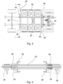
- Fig. 3 schematically illustrates a view from above of a vehicle with a battery box arrangement according to an example.
- the first end part 28 of each elongated beam element 22, 23 is connected to the first battery box module 30 of the battery box 20.
- the second end part 34 of each elongated beam element 22, 23 is connected to the second battery box module 36 of the battery box 20.
- the first elongated beam element 22 is connected to the first end wall 44 of the first and second battery box module 30, 36 and the second elongated beam element 23 is connected to the second end wall 46 of the of the first and second battery box module 30, 36.
- Fig. 4 illustrates a section view through line I - I in fig. 3 of the first elongated beam element 22 connected of the battery box arrangement 2.
- the vibration damping elements 24 comprises a bushing 56, which at least in part embraces the first elongated beam element 22.
- the first elongated beam element 22 passes through the chassis frame 26.
- the first elongated beam element 22 is connected to the chassis frame 26 by means of the bushing 56.
- Fig. 5 schematically illustrates a view in perspective of a vehicle with a battery box arrangement according to an example.
- the first end part 28 of each elongated beam element 22, 23 is connected to the first battery box module 30 of the battery box 20.
- the second end part 34 of each elongated beam element 22, 23 is connected to the second battery box module 36 of the battery box 20.
- the first elongated beam element 22 is connected to the first end wall 44 of the first and second battery box module 30, 36 and the second elongated beam element 23 is connected to the second end wall 46 of the of the first and second battery box module 30, 36.
- the first and second elongated beam elements 22, 23 passes through the chassis frame 26.
- Figures 6a - 6b schematically illustrate side views of a vehicle with a battery box arrangement according to an example.
- the first elongated beam element 22 is connected to the first end wall 44 of the first and second battery box module 30, 36 and the second elongated beam element 23 is connected to the second end wall 46 of the of the first and second battery box module 30, 36.
- the first and second elongated beam elements 22, 23 are connected to the middle of the first and second end walls 44, 46.
- Such configuration will create a small distance between the upper part of the chassis frame 26 and the lowermost part of the battery box 20.
- the first and second elongated beam elements 22, 23 are connected to an upper part of the first and second end walls 44, 46.
- Such configuration will create an increased distance between the upper part of the chassis frame 26 and the lowermost part of the battery box 20.
- Fig. 7 schematically illustrates a view from above of a vehicle 1 with a battery box arrangement 2 according to an example.
- One cross member 42 is via a vibration damping member 60 configured to connect the first and second battery box module 30, 36 at one point to a strut 62 of the chassis frame 26 of the vehicle 1.
- the chassis frame 26 may comprise two frame beams 40, which are parallel and which are longitudinal arranged in the vehicle 1.
- the strut 62 or cross bar is arranged between the frame beams 40.
- the strut 62 connects the two frame beams 40.
- the strut 62 extends in a transvers direction in relation to the longitudinal direction of the two frame beams 40.
- the strut 62 extends in a parallel direction in relation to the cross member 42, which is connected to the first and second battery box modules 30, 36.
- the battery box arrangement 2 comprises in one end the vibration damping member 60, which is configured to connect the first and second battery box module 30, 36 at one point to the strut 62 of the chassis frame 26. In the other end the first and second battery box modules 30, 36 are connected to the chassis frame 26 by means of the second elongated beam element 23.
- the battery box 20 will in this configuration be connected to the chassis frame 26 in three points.
Landscapes
- Engineering & Computer Science (AREA)
- Mechanical Engineering (AREA)
- Transportation (AREA)
- Chemical & Material Sciences (AREA)
- Combustion & Propulsion (AREA)
- Sustainable Energy (AREA)
- Life Sciences & Earth Sciences (AREA)
- Sustainable Development (AREA)
- Power Engineering (AREA)
- Chemical Kinetics & Catalysis (AREA)
- Electrochemistry (AREA)
- General Chemical & Material Sciences (AREA)
- Aviation & Aerospace Engineering (AREA)
- Arrangement Or Mounting Of Propulsion Units For Vehicles (AREA)
- Battery Mounting, Suspending (AREA)
Claims (13)
- Batteriekastenanordnung (2) für ein Fahrzeug (1), wobei die Anordnung (2) umfasst:einen Batteriekasten (20), der derart eingerichtet ist, dass er wenigstens eine elektrische Batterie (14) umfasst;wenigstens ein längliches Trägerelement (22, 23), das mit dem Batteriekasten (20) verbunden ist; undwenigstens ein schwingungsdämpfendes Element (24), das zum Verbinden des wenigstens einen länglichen Trägerelements (22, 23) mit einem Fahrgestellrahmen (26) des Fahrzeugs (1) eingerichtet ist;wobei das wenigstens eine längliche Trägerelement (22, 23) derart eingerichtet ist, dass es sich quer zu dem Fahrgestellrahmen (26) des Fahrzeugs (1) erstreckt;wobei ein erstes Endteil (28) des wenigstens einen länglichen Trägerelements (22, 23) mit einem ersten Batteriekastenmodul (30) des Batteriekastens (20) verbunden ist, undwobei ein zweites Endteil (34) des wenigstens einen länglichen Trägerelements (23) mit einem zweiten Batteriekastenmodul (36) des Batteriekastens (20) verbunden ist,dadurch gekennzeichnet, dass das längliche Trägerelement (22, 23) rohrförmig oder eine Vollstange ist, und wobei das wenigstens eine schwingungsdämpfende Element (24) eine Buchse (56) aufweist, die das wenigstens eine längliche Trägerelement (22, 23) teilweise umgreift.
- Batteriekastenanordnung (2) nach Anspruch 1, wobei das erste Batteriekastenmodul (30) zur Anordnung auf einer ersten Seite des Chassisrahmens (26) des Fahrzeugs (1) und das zweite Batteriekastenmodul (36) zur Anordnung auf einer zweiten Seite des Chassisrahmens (26) des Fahrzeugs (1) eingerichtet ist.
- Batteriekastenanordnung (2) nach einem der Ansprüche 1 und 2, wobei ein drittes Batteriekastenmodul (38) des Batteriekastens (20) mit dem ersten und dem zweiten Batteriekastenmodul (30, 36) verbunden ist.
- Batteriekastenanordnung (2) nach Anspruch 3, wobei das dritte Batteriekastenmodul (38) zur Anordnung zwischen zwei Rahmenträgern (40) des Chassisrahmens (26) des Fahrzeugs (1) eingerichtet ist.
- Batteriekastenanordnung (2) nach einem der vorangehenden Ansprüche, wobei wenigstens ein Querträger (42) mit dem ersten und dem zweiten Batteriekastenmodul (30, 36) verbunden ist.
- Batteriekastenanordnung (2) nach Anspruch 5, wobei der wenigstens eine Querträger (42) über wenigstens ein schwingungsdämpfendes Element (60) dazu eingerichtet ist, dass er das erste und zweite Batteriekastenmodul (30, 36) an einem Punkt mit einer Strebe (62) des F Chassisrahmens (26) des Fahrzeugs (1) verbindet.
- Batteriekastenanordnung (2) nach einem der Ansprüche 1-5, wobei das wenigstens eine längliche Trägerelement (22, 23) ein erstes längliches Trägerelement (22) und ein zweites längliches Trägerelement (23) umfasst.
- Batteriekastenanordnung (2) nach Anspruch 7, wobei das erste längliche Trägerelement (22) mit einer ersten Endwand (44) des ersten und zweiten Batteriekastenmoduls (30, 36) verbunden ist und wobei das zweite längliche Trägerelement (23) mit einer zweiten Endwand (46) des ersten und zweiten Batteriekastenmoduls (30, 36) verbunden ist.
- Batteriekastenanordnung (2) nach einem der vorangehenden Ansprüche, wobei an Wänden (50) des Batteriekastens (20) stoßdämpfende Wandelemente (48) angeordnet sind.
- Batteriekastenanordnung (2) nach einem der vorangehenden Ansprüche, wobei in dem Batteriekasten (20) Querwände (52) angeordnet sind.
- Batteriekastenanordnung (2) nach einem der vorangehenden Ansprüche, wobei zwischen dem Batteriekasten (20) und dem Chassisrahmens (26) Stoßschutzpads (54) angeordnet sind.
- Batteriekastenanordnung (2) nach einem der vorangehenden Ansprüche, wobei der Batteriekasten (20) derart eingerichtet ist, dass er wenigstens einen Kraftstofftank (21) umfasst.
- Fahrzeug (1) mit einer Batteriekastenanordnung (2) nach einem der vorangehenden Ansprüche.
Applications Claiming Priority (2)
| Application Number | Priority Date | Filing Date | Title |
|---|---|---|---|
| SE1951270A SE543973C2 (en) | 2019-11-06 | 2019-11-06 | A battery box arrangement |
| PCT/SE2020/050981 WO2021091448A1 (en) | 2019-11-06 | 2020-10-15 | A battery box arrangement |
Publications (3)
| Publication Number | Publication Date |
|---|---|
| EP4054879A1 EP4054879A1 (de) | 2022-09-14 |
| EP4054879A4 EP4054879A4 (de) | 2023-12-20 |
| EP4054879B1 true EP4054879B1 (de) | 2025-02-26 |
Family
ID=75848060
Family Applications (1)
| Application Number | Title | Priority Date | Filing Date |
|---|---|---|---|
| EP20885986.8A Active EP4054879B1 (de) | 2019-11-06 | 2020-10-15 | Batteriekastenanordnung |
Country Status (6)
| Country | Link |
|---|---|
| US (1) | US12070996B2 (de) |
| EP (1) | EP4054879B1 (de) |
| CN (1) | CN114667234B (de) |
| BR (1) | BR112022007877A2 (de) |
| SE (1) | SE543973C2 (de) |
| WO (1) | WO2021091448A1 (de) |
Families Citing this family (19)
| Publication number | Priority date | Publication date | Assignee | Title |
|---|---|---|---|---|
| WO2020215023A1 (en) * | 2019-04-19 | 2020-10-22 | Hexagon Purus North America Holdings Inc. | Electric front end accessory devices assembly |
| CA3161967C (en) | 2019-11-26 | 2025-05-13 | Hexagon Purus North America Holdings Inc. | POWER DISTRIBUTION FOR ELECTRIC VEHICLES AND MOTOR CONTROL MODULE |
| US11498435B2 (en) * | 2020-07-30 | 2022-11-15 | Dana Heavy Vehicle Systems Group, Llc | Systems and methods for an electrified heavy-duty vehicle |
| DE102020121828A1 (de) * | 2020-08-20 | 2022-02-24 | Man Truck & Bus Se | Motorhalter und Fahrzeug mit einem ebensolchen Motorhalter |
| JP7525365B2 (ja) * | 2020-10-09 | 2024-07-30 | ダイムラー トラック エージー | バッテリパックの支持装置、及び電動トラック |
| CN112477573A (zh) * | 2020-11-10 | 2021-03-12 | 浙江吉利控股集团有限公司 | 一种吊装换电式运载车辆 |
| CA3205080A1 (en) | 2020-12-11 | 2022-06-16 | Hexagon Purus North America Holdings Inc. | Trailer hookup breakaway mitigation systems and methods |
| EP4341115A1 (de) * | 2021-05-18 | 2024-03-27 | Volvo Truck Corporation | Modulares system für ein fahrzeug, fahrzeug und installationsverfahren |
| WO2022268324A1 (en) * | 2021-06-24 | 2022-12-29 | Volvo Truck Corporation | An energy storage mounting system for a vehicle |
| JP7775539B2 (ja) * | 2021-07-21 | 2025-11-26 | メルセデス・ベンツ グループ アクチェンゲゼルシャフト | トラック車両 |
| US12409718B2 (en) * | 2021-09-09 | 2025-09-09 | Oshkosh Corporation | Structural refuse vehicle body with undermounted batteries |
| CN115284950B (zh) * | 2021-11-30 | 2024-10-18 | 奥动新能源汽车科技有限公司 | 用于电动车辆的换电托盘和电动车辆 |
| NL2031489B1 (en) * | 2022-04-04 | 2023-10-25 | Daf Trucks Nv | A road vehicle |
| DE102022123162B3 (de) * | 2022-09-12 | 2023-08-31 | Trailer Dynamics Gmbh | Nutzfahrzeug mit Batteriekasten |
| JP7666480B2 (ja) * | 2022-10-11 | 2025-04-22 | トヨタ自動車株式会社 | フレーム車のバッテリ搭載構造 |
| EP4574488A1 (de) * | 2023-12-21 | 2025-06-25 | Volvo Truck Corporation | Batterie-aufprallschutzanordnung |
| FR3159351A1 (fr) * | 2024-02-16 | 2025-08-22 | Renault Sas | Dispositif de stockage d’énergie pour un véhicule comprenant un réservoir et une batterie électrochimique |
| EP4722011A1 (de) * | 2024-10-02 | 2026-04-08 | Volvo Truck Corporation | Energiespeicheranordnung mit offenendigen fächern |
| CN119550800B (zh) * | 2024-12-20 | 2025-09-30 | 江苏汤臣汽车零部件有限公司 | 车辆用电池包安装结构和方法 |
Family Cites Families (27)
| Publication number | Priority date | Publication date | Assignee | Title |
|---|---|---|---|---|
| JPH0717265A (ja) * | 1993-07-06 | 1995-01-20 | Nippon Home Keizai Kenkyusho:Kk | 電気自動車動力用二次電池の自動車への装架装置 |
| KR100257872B1 (ko) * | 1996-11-13 | 2000-06-01 | 정몽규 | 전기 자동차의 배터리 트레이 보강구조 |
| DE10327839A1 (de) * | 2003-06-20 | 2005-01-05 | Arvinmeritor Gmbh | Fahrzeugdachmodul |
| KR20060024917A (ko) * | 2004-09-15 | 2006-03-20 | 현대모비스 주식회사 | 차량의 액추에이터 전원보정장치 및 보정방법 |
| SE529231C2 (sv) | 2005-10-17 | 2007-06-05 | Volvo Lastvagnar Ab | Motorfordon med bakmonterad batterilåda |
| US8122989B2 (en) | 2005-12-29 | 2012-02-28 | Volvo Group North America, Llc | Battery box system and method |
| US7270208B2 (en) * | 2005-12-30 | 2007-09-18 | Taiwan An I Co., Ltd. | Battery carrier sliding device of an electrical wheel chair |
| CN102059959B (zh) * | 2010-04-01 | 2012-10-03 | 张瑞麟 | 新能源或混合动力的微型电动汽车 |
| JP5555739B2 (ja) | 2012-04-11 | 2014-07-23 | 富士重工業株式会社 | 車両のバッテリ装置 |
| CN105473371B (zh) * | 2013-07-24 | 2017-08-01 | 英属盖曼群岛商立凯绿能移动科技股份有限公司 | 中型电动车辆的可拆卸高压隔离结构 |
| CN104319359A (zh) * | 2014-11-07 | 2015-01-28 | 国家电网公司 | 一种电动汽车及其电池总成架 |
| JP6299585B2 (ja) * | 2014-12-22 | 2018-03-28 | トヨタ自動車株式会社 | 燃料電池システム |
| US10308132B2 (en) * | 2016-05-09 | 2019-06-04 | Nikola Corporation | Electric utility terrain vehicle |
| US10112471B2 (en) * | 2016-05-18 | 2018-10-30 | Sharp Kabushiki Kaisha | Battery-driven traveling device |
| GB2553537B (en) | 2016-09-07 | 2021-12-08 | Arrival Ltd | Battery box |
| CN106299188A (zh) | 2016-09-29 | 2017-01-04 | 常州普莱德新能源电池科技有限公司 | 一种电动汽车用软包电池模块 |
| US10272758B2 (en) * | 2016-11-02 | 2019-04-30 | Proterra Inc. | Battery system of an electric vehicle |
| JP2018118673A (ja) * | 2017-01-26 | 2018-08-02 | 日産ライトトラック株式会社 | 車両のバッテリ支持構造 |
| JP7163059B2 (ja) * | 2018-04-27 | 2022-10-31 | メルセデス・ベンツ グループ アクチェンゲゼルシャフト | 車両用バッテリハウジング、車両用バッテリパック、及び電動車両 |
| CN108674167A (zh) | 2018-06-29 | 2018-10-19 | 吉林大学青岛汽车研究院 | 一种电池包横摆悬置的电动汽车底盘 |
| CN208714935U (zh) | 2018-08-30 | 2019-04-09 | 安徽华菱汽车有限公司 | 电动运输车电池安装系统及电动厢式运输车 |
| US10493837B1 (en) * | 2018-10-11 | 2019-12-03 | Paccar Inc | Chassis mounted assemblies for electric or hybrid vehicles |
| CN112805175B (zh) * | 2018-10-12 | 2025-05-23 | 沃尔沃卡车集团 | 用于车辆的电池组布置、车架布置和车辆 |
| CN110077464B (zh) * | 2019-05-17 | 2020-02-04 | 佟玉振 | 适用于纯电动新能源汽车的底盘 |
| EP3925807B1 (de) * | 2020-06-16 | 2024-01-24 | Volvo Truck Corporation | Batteriemodulträgeranordnung |
| US11820241B2 (en) * | 2020-11-30 | 2023-11-21 | Nikola Corporation | Battery pack assembly |
| US11845346B2 (en) * | 2021-02-10 | 2023-12-19 | Toyota Motor Engineering & Manufacturing North America, Inc. | Carrier assembly for multiple fuel cells |
-
2019
- 2019-11-06 SE SE1951270A patent/SE543973C2/en unknown
-
2020
- 2020-10-15 WO PCT/SE2020/050981 patent/WO2021091448A1/en not_active Ceased
- 2020-10-15 BR BR112022007877A patent/BR112022007877A2/pt unknown
- 2020-10-15 US US17/773,170 patent/US12070996B2/en active Active
- 2020-10-15 EP EP20885986.8A patent/EP4054879B1/de active Active
- 2020-10-15 CN CN202080073406.6A patent/CN114667234B/zh active Active
Also Published As
| Publication number | Publication date |
|---|---|
| BR112022007877A2 (pt) | 2022-07-12 |
| CN114667234A (zh) | 2022-06-24 |
| EP4054879A1 (de) | 2022-09-14 |
| SE1951270A1 (en) | 2021-05-07 |
| CN114667234B (zh) | 2024-02-02 |
| US12070996B2 (en) | 2024-08-27 |
| WO2021091448A1 (en) | 2021-05-14 |
| SE543973C2 (en) | 2021-10-12 |
| EP4054879A4 (de) | 2023-12-20 |
| US20240149654A1 (en) | 2024-05-09 |
Similar Documents
| Publication | Publication Date | Title |
|---|---|---|
| EP4054879B1 (de) | Batteriekastenanordnung | |
| CN113815394B (zh) | 电池模块支撑装置 | |
| EP3444138B1 (de) | Fahrzeug | |
| CN102686430B (zh) | 包括布置在车辆行走装置附近的电发动机组及其供电模块的机动车辆 | |
| KR102264750B1 (ko) | 차량용 파워 유닛 구조 | |
| JP4649849B2 (ja) | 蓄電機構の取付構造 | |
| US20190366834A1 (en) | Electric machine integrated axle assemblies for electrified vehicles | |
| US8496268B2 (en) | Universal chassis | |
| EP4056456B1 (de) | Tragvorrichtung für fahrzeugbatteriepaket und elektrofahrzeug | |
| KR20220039805A (ko) | 자동차의 하부 구조 | |
| KR20140040698A (ko) | 전기 에너지 저장기의, 지지 .구조 요소로서 형성된 하우징을 포함하는 차량 | |
| US10710636B2 (en) | Vehicle front portion structure | |
| CN103707928A (zh) | 带有用于至少一个商用车构件的容纳容器的框架承载结构 | |
| EP3964426B1 (de) | Rahmen für elektrolastwagen | |
| US12005958B2 (en) | Universal chassis frame with variable rear axle positions for medium/heavy duty configurable electric trucks | |
| CN114786979A (zh) | 电驱动单元 | |
| WO2010022447A1 (en) | Electric engine arrangement | |
| EP3937271A1 (de) | Fahrzeug | |
| WO2026066315A1 (zh) | 前副车架及车辆 | |
| JP5469898B2 (ja) | 車体構造 | |
| EP4257454B1 (de) | Strassenfahrzeug mit batteriebefestigung | |
| EP4190601A1 (de) | Verbessertes aufhängungssystem für ein fahrzeug | |
| CN222820136U (zh) | 车架及车辆 | |
| JP2022138927A (ja) | 車台 | |
| CN119300996A (zh) | 用于电动车辆的结构 |
Legal Events
| Date | Code | Title | Description |
|---|---|---|---|
| STAA | Information on the status of an ep patent application or granted ep patent |
Free format text: STATUS: THE INTERNATIONAL PUBLICATION HAS BEEN MADE |
|
| PUAI | Public reference made under article 153(3) epc to a published international application that has entered the european phase |
Free format text: ORIGINAL CODE: 0009012 |
|
| STAA | Information on the status of an ep patent application or granted ep patent |
Free format text: STATUS: REQUEST FOR EXAMINATION WAS MADE |
|
| 17P | Request for examination filed |
Effective date: 20220607 |
|
| AK | Designated contracting states |
Kind code of ref document: A1 Designated state(s): AL AT BE BG CH CY CZ DE DK EE ES FI FR GB GR HR HU IE IS IT LI LT LU LV MC MK MT NL NO PL PT RO RS SE SI SK SM TR |
|
| DAV | Request for validation of the european patent (deleted) | ||
| DAX | Request for extension of the european patent (deleted) | ||
| P01 | Opt-out of the competence of the unified patent court (upc) registered |
Effective date: 20230518 |
|
| A4 | Supplementary search report drawn up and despatched |
Effective date: 20231121 |
|
| RIC1 | Information provided on ipc code assigned before grant |
Ipc: B62D 21/15 20060101ALN20231115BHEP Ipc: B62D 1/02 20060101ALN20231115BHEP Ipc: B60L 50/60 20190101ALN20231115BHEP Ipc: B60L 3/00 20190101ALN20231115BHEP Ipc: B60K 1/04 20190101ALI20231115BHEP Ipc: B60L 50/64 20190101AFI20231115BHEP |
|
| GRAP | Despatch of communication of intention to grant a patent |
Free format text: ORIGINAL CODE: EPIDOSNIGR1 |
|
| STAA | Information on the status of an ep patent application or granted ep patent |
Free format text: STATUS: GRANT OF PATENT IS INTENDED |
|
| RIC1 | Information provided on ipc code assigned before grant |
Ipc: B62D 21/09 20060101ALN20240911BHEP Ipc: B62D 21/02 20060101ALN20240911BHEP Ipc: B62D 21/15 20060101ALN20240911BHEP Ipc: B62D 1/02 20060101ALN20240911BHEP Ipc: B60L 50/60 20190101ALN20240911BHEP Ipc: B60L 3/00 20190101ALN20240911BHEP Ipc: B60K 1/04 20190101ALI20240911BHEP Ipc: B60L 50/64 20190101AFI20240911BHEP |
|
| INTG | Intention to grant announced |
Effective date: 20240925 |
|
| GRAS | Grant fee paid |
Free format text: ORIGINAL CODE: EPIDOSNIGR3 |
|
| GRAA | (expected) grant |
Free format text: ORIGINAL CODE: 0009210 |
|
| STAA | Information on the status of an ep patent application or granted ep patent |
Free format text: STATUS: THE PATENT HAS BEEN GRANTED |
|
| AK | Designated contracting states |
Kind code of ref document: B1 Designated state(s): AL AT BE BG CH CY CZ DE DK EE ES FI FR GB GR HR HU IE IS IT LI LT LU LV MC MK MT NL NO PL PT RO RS SE SI SK SM TR |
|
| REG | Reference to a national code |
Ref country code: GB Ref legal event code: FG4D |
|
| REG | Reference to a national code |
Ref country code: CH Ref legal event code: EP |
|
| REG | Reference to a national code |
Ref country code: DE Ref legal event code: R096 Ref document number: 602020046981 Country of ref document: DE |
|
| REG | Reference to a national code |
Ref country code: IE Ref legal event code: FG4D |
|
| REG | Reference to a national code |
Ref country code: SE Ref legal event code: TRGR |
|
| REG | Reference to a national code |
Ref country code: NL Ref legal event code: MP Effective date: 20250226 |
|
| PG25 | Lapsed in a contracting state [announced via postgrant information from national office to epo] |
Ref country code: RS Free format text: LAPSE BECAUSE OF FAILURE TO SUBMIT A TRANSLATION OF THE DESCRIPTION OR TO PAY THE FEE WITHIN THE PRESCRIBED TIME-LIMIT Effective date: 20250526 |
|
| PG25 | Lapsed in a contracting state [announced via postgrant information from national office to epo] |
Ref country code: FI Free format text: LAPSE BECAUSE OF FAILURE TO SUBMIT A TRANSLATION OF THE DESCRIPTION OR TO PAY THE FEE WITHIN THE PRESCRIBED TIME-LIMIT Effective date: 20250226 |
|
| PG25 | Lapsed in a contracting state [announced via postgrant information from national office to epo] |
Ref country code: PL Free format text: LAPSE BECAUSE OF FAILURE TO SUBMIT A TRANSLATION OF THE DESCRIPTION OR TO PAY THE FEE WITHIN THE PRESCRIBED TIME-LIMIT Effective date: 20250226 |
|
| PG25 | Lapsed in a contracting state [announced via postgrant information from national office to epo] |
Ref country code: ES Free format text: LAPSE BECAUSE OF FAILURE TO SUBMIT A TRANSLATION OF THE DESCRIPTION OR TO PAY THE FEE WITHIN THE PRESCRIBED TIME-LIMIT Effective date: 20250226 |
|
| REG | Reference to a national code |
Ref country code: LT Ref legal event code: MG9D |
|
| PG25 | Lapsed in a contracting state [announced via postgrant information from national office to epo] |
Ref country code: NO Free format text: LAPSE BECAUSE OF FAILURE TO SUBMIT A TRANSLATION OF THE DESCRIPTION OR TO PAY THE FEE WITHIN THE PRESCRIBED TIME-LIMIT Effective date: 20250526 Ref country code: IS Free format text: LAPSE BECAUSE OF FAILURE TO SUBMIT A TRANSLATION OF THE DESCRIPTION OR TO PAY THE FEE WITHIN THE PRESCRIBED TIME-LIMIT Effective date: 20250626 |
|
| PG25 | Lapsed in a contracting state [announced via postgrant information from national office to epo] |
Ref country code: NL Free format text: LAPSE BECAUSE OF FAILURE TO SUBMIT A TRANSLATION OF THE DESCRIPTION OR TO PAY THE FEE WITHIN THE PRESCRIBED TIME-LIMIT Effective date: 20250226 |
|
| PG25 | Lapsed in a contracting state [announced via postgrant information from national office to epo] |
Ref country code: HR Free format text: LAPSE BECAUSE OF FAILURE TO SUBMIT A TRANSLATION OF THE DESCRIPTION OR TO PAY THE FEE WITHIN THE PRESCRIBED TIME-LIMIT Effective date: 20250226 |
|
| PG25 | Lapsed in a contracting state [announced via postgrant information from national office to epo] |
Ref country code: LV Free format text: LAPSE BECAUSE OF FAILURE TO SUBMIT A TRANSLATION OF THE DESCRIPTION OR TO PAY THE FEE WITHIN THE PRESCRIBED TIME-LIMIT Effective date: 20250226 Ref country code: PT Free format text: LAPSE BECAUSE OF FAILURE TO SUBMIT A TRANSLATION OF THE DESCRIPTION OR TO PAY THE FEE WITHIN THE PRESCRIBED TIME-LIMIT Effective date: 20250626 |
|
| PG25 | Lapsed in a contracting state [announced via postgrant information from national office to epo] |
Ref country code: BG Free format text: LAPSE BECAUSE OF FAILURE TO SUBMIT A TRANSLATION OF THE DESCRIPTION OR TO PAY THE FEE WITHIN THE PRESCRIBED TIME-LIMIT Effective date: 20250226 Ref country code: GR Free format text: LAPSE BECAUSE OF FAILURE TO SUBMIT A TRANSLATION OF THE DESCRIPTION OR TO PAY THE FEE WITHIN THE PRESCRIBED TIME-LIMIT Effective date: 20250527 |
|
| REG | Reference to a national code |
Ref country code: AT Ref legal event code: MK05 Ref document number: 1770332 Country of ref document: AT Kind code of ref document: T Effective date: 20250226 |
|
| PG25 | Lapsed in a contracting state [announced via postgrant information from national office to epo] |
Ref country code: SM Free format text: LAPSE BECAUSE OF FAILURE TO SUBMIT A TRANSLATION OF THE DESCRIPTION OR TO PAY THE FEE WITHIN THE PRESCRIBED TIME-LIMIT Effective date: 20250226 |
|
| PG25 | Lapsed in a contracting state [announced via postgrant information from national office to epo] |
Ref country code: DK Free format text: LAPSE BECAUSE OF FAILURE TO SUBMIT A TRANSLATION OF THE DESCRIPTION OR TO PAY THE FEE WITHIN THE PRESCRIBED TIME-LIMIT Effective date: 20250226 |
|
| PG25 | Lapsed in a contracting state [announced via postgrant information from national office to epo] |
Ref country code: IT Free format text: LAPSE BECAUSE OF FAILURE TO SUBMIT A TRANSLATION OF THE DESCRIPTION OR TO PAY THE FEE WITHIN THE PRESCRIBED TIME-LIMIT Effective date: 20250226 |
|
| PGFP | Annual fee paid to national office [announced via postgrant information from national office to epo] |
Ref country code: GB Payment date: 20250828 Year of fee payment: 6 Ref country code: BE Payment date: 20250917 Year of fee payment: 6 |
|
| PG25 | Lapsed in a contracting state [announced via postgrant information from national office to epo] |
Ref country code: AT Free format text: LAPSE BECAUSE OF FAILURE TO SUBMIT A TRANSLATION OF THE DESCRIPTION OR TO PAY THE FEE WITHIN THE PRESCRIBED TIME-LIMIT Effective date: 20250226 |
|
| PGFP | Annual fee paid to national office [announced via postgrant information from national office to epo] |
Ref country code: FR Payment date: 20250908 Year of fee payment: 6 |
|
| PGFP | Annual fee paid to national office [announced via postgrant information from national office to epo] |
Ref country code: SE Payment date: 20250910 Year of fee payment: 6 |
|
| PG25 | Lapsed in a contracting state [announced via postgrant information from national office to epo] |
Ref country code: EE Free format text: LAPSE BECAUSE OF FAILURE TO SUBMIT A TRANSLATION OF THE DESCRIPTION OR TO PAY THE FEE WITHIN THE PRESCRIBED TIME-LIMIT Effective date: 20250226 Ref country code: CZ Free format text: LAPSE BECAUSE OF FAILURE TO SUBMIT A TRANSLATION OF THE DESCRIPTION OR TO PAY THE FEE WITHIN THE PRESCRIBED TIME-LIMIT Effective date: 20250226 |
|
| PG25 | Lapsed in a contracting state [announced via postgrant information from national office to epo] |
Ref country code: RO Free format text: LAPSE BECAUSE OF FAILURE TO SUBMIT A TRANSLATION OF THE DESCRIPTION OR TO PAY THE FEE WITHIN THE PRESCRIBED TIME-LIMIT Effective date: 20250226 |
|
| PG25 | Lapsed in a contracting state [announced via postgrant information from national office to epo] |
Ref country code: SK Free format text: LAPSE BECAUSE OF FAILURE TO SUBMIT A TRANSLATION OF THE DESCRIPTION OR TO PAY THE FEE WITHIN THE PRESCRIBED TIME-LIMIT Effective date: 20250226 |
|
| REG | Reference to a national code |
Ref country code: DE Ref legal event code: R097 Ref document number: 602020046981 Country of ref document: DE |
|
| PLBE | No opposition filed within time limit |
Free format text: ORIGINAL CODE: 0009261 |
|
| STAA | Information on the status of an ep patent application or granted ep patent |
Free format text: STATUS: NO OPPOSITION FILED WITHIN TIME LIMIT |
|
| PGFP | Annual fee paid to national office [announced via postgrant information from national office to epo] |
Ref country code: DE Payment date: 20250902 Year of fee payment: 6 |
|
| 26N | No opposition filed |
Effective date: 20251127 |