EP4054873B1 - Modularer stellantrieb für flugzeugvorrichtungen und modulares aktives gitterverschlusssystem mit einer reduzierten anzahl von lamellen - Google Patents
Modularer stellantrieb für flugzeugvorrichtungen und modulares aktives gitterverschlusssystem mit einer reduzierten anzahl von lamellen Download PDFInfo
- Publication number
- EP4054873B1 EP4054873B1 EP20842889.6A EP20842889A EP4054873B1 EP 4054873 B1 EP4054873 B1 EP 4054873B1 EP 20842889 A EP20842889 A EP 20842889A EP 4054873 B1 EP4054873 B1 EP 4054873B1
- Authority
- EP
- European Patent Office
- Prior art keywords
- end cap
- actuator
- base
- integrated
- grille shutter
- Prior art date
- Legal status (The legal status is an assumption and is not a legal conclusion. Google has not performed a legal analysis and makes no representation as to the accuracy of the status listed.)
- Active
Links
Images






Classifications
-
- B—PERFORMING OPERATIONS; TRANSPORTING
- B60—VEHICLES IN GENERAL
- B60K—ARRANGEMENT OR MOUNTING OF PROPULSION UNITS OR OF TRANSMISSIONS IN VEHICLES; ARRANGEMENT OR MOUNTING OF PLURAL DIVERSE PRIME-MOVERS IN VEHICLES; AUXILIARY DRIVES FOR VEHICLES; INSTRUMENTATION OR DASHBOARDS FOR VEHICLES; ARRANGEMENTS IN CONNECTION WITH COOLING, AIR INTAKE, GAS EXHAUST OR FUEL SUPPLY OF PROPULSION UNITS IN VEHICLES
- B60K11/00—Arrangement in connection with cooling of propulsion units
- B60K11/08—Air inlets for cooling; Shutters or blinds therefor
- B60K11/085—Air inlets for cooling; Shutters or blinds therefor with adjustable shutters or blinds
-
- F—MECHANICAL ENGINEERING; LIGHTING; HEATING; WEAPONS; BLASTING
- F24—HEATING; RANGES; VENTILATING
- F24F—AIR-CONDITIONING; AIR-HUMIDIFICATION; VENTILATION; USE OF AIR CURRENTS FOR SCREENING
- F24F13/00—Details common to, or for air-conditioning, air-humidification, ventilation or use of air currents for screening
- F24F13/08—Air-flow control members, e.g. louvres, grilles, flaps or guide plates
- F24F13/082—Grilles, registers or guards
-
- F—MECHANICAL ENGINEERING; LIGHTING; HEATING; WEAPONS; BLASTING
- F24—HEATING; RANGES; VENTILATING
- F24F—AIR-CONDITIONING; AIR-HUMIDIFICATION; VENTILATION; USE OF AIR CURRENTS FOR SCREENING
- F24F13/00—Details common to, or for air-conditioning, air-humidification, ventilation or use of air currents for screening
- F24F13/08—Air-flow control members, e.g. louvres, grilles, flaps or guide plates
- F24F13/10—Air-flow control members, e.g. louvres, grilles, flaps or guide plates movable, e.g. dampers
-
- B—PERFORMING OPERATIONS; TRANSPORTING
- B60—VEHICLES IN GENERAL
- B60Y—INDEXING SCHEME RELATING TO ASPECTS CROSS-CUTTING VEHICLE TECHNOLOGY
- B60Y2306/00—Other features of vehicle sub-units
- B60Y2306/05—Cooling
-
- B—PERFORMING OPERATIONS; TRANSPORTING
- B60—VEHICLES IN GENERAL
- B60Y—INDEXING SCHEME RELATING TO ASPECTS CROSS-CUTTING VEHICLE TECHNOLOGY
- B60Y2400/00—Special features of vehicle units
- B60Y2400/40—Actuators for moving a controlled member
-
- B—PERFORMING OPERATIONS; TRANSPORTING
- B60—VEHICLES IN GENERAL
- B60Y—INDEXING SCHEME RELATING TO ASPECTS CROSS-CUTTING VEHICLE TECHNOLOGY
- B60Y2410/00—Constructional features of vehicle sub-units
- B60Y2410/10—Housings
-
- Y—GENERAL TAGGING OF NEW TECHNOLOGICAL DEVELOPMENTS; GENERAL TAGGING OF CROSS-SECTIONAL TECHNOLOGIES SPANNING OVER SEVERAL SECTIONS OF THE IPC; TECHNICAL SUBJECTS COVERED BY FORMER USPC CROSS-REFERENCE ART COLLECTIONS [XRACs] AND DIGESTS
- Y02—TECHNOLOGIES OR APPLICATIONS FOR MITIGATION OR ADAPTATION AGAINST CLIMATE CHANGE
- Y02T—CLIMATE CHANGE MITIGATION TECHNOLOGIES RELATED TO TRANSPORTATION
- Y02T10/00—Road transport of goods or passengers
- Y02T10/80—Technologies aiming to reduce greenhouse gasses emissions common to all road transportation technologies
- Y02T10/88—Optimized components or subsystems, e.g. lighting, actively controlled glasses
Definitions
- the present invention relates to a modular active grille shutter system with a reduced actuator pocket to provide a system having a reduced number of vanes as the base components of the system.
- the large cooling apertures provided by conventional active grille shutter systems are not necessarily due to the fact that there are no large radiators for cooling an internal combustion engine. Electric vehicles in particular do require a certain amount of cooling for the battery packs; however, the cooling aperture is much shorter and does not require as much vertical height. As a result, the number of vanes needed for an active grille shutter system on an electric vehicle is less than five, preferably three vanes, which shortens the height of the active grille shutter system.
- the frame of the active grille system will be smaller, which also requires the actuator pocket of the frame and any actuator for the active grille shutter system to also be smaller. Therefore, it is an object of the invention to provide a modular active grille shutter system having a reduced actuator pocket size. It is also an object of the invention to provide an actuator that is also smaller and can fit within the smaller pocket size. Additionally, it is desirable to develop an actuator pocket and actuator that provides various output axes so that the driven vane and actuator is not always fixed to one location on the modular active grille shutter system, but instead any one of the vanes can be the driven vane.
- the positioning of an actuator during assembly is often complex and involves motions and various fastener types to fix the actuator to the assembly.
- the connector is typically connected in a downward location.
- Typical actuators today are not able to be used in a package space allotted for a grille having three vanes.
- actuators today typically require new software programming to develop the communication method between the aero device and the vehicle. This is typically custom and can be a significant portion of the system development timeline.
- DOE degree of freedom
- WO 2019/020510 A1 discloses a grille shutter system for closing an air inlet of a motor vehicle front end.
- the known system comprises a support frame in which at least one set of pivoting flaps is installed, at least one control element configured to control the positioning of the flaps, as well as an actuator having attachment holes, a housing configured to receive the actuator and a cap that covers the housing, with the cap and the housing cooperating by means of snap-fastening, the housing having positioning elements, intended to be inserted into the attachment holes, and the cap having at least one specific shape configured to keep the actuator stationary relative to the positioning elements when the cap is snap-fastened onto the housing.
- the invention provides a modular active grille shutter system with the features of claim1 .
- the active grille shutter system includes a frame connected to an automobile at a location forward of an engine or energy source such as a battery pack.
- the frame is formed from assembling several different sized components to create a cooling aperture.
- the modular active grille shutter system includes an active grille shutter system having a frame located in a cooling pathway of a power source for the vehicle.
- the frame includes a base end cap with an actuator pocket having a plurality of alternate actuator output axes located within the actuator pocket.
- the modular active grille shutter system also includes a plurality of vanes extending across the cooling aperture of the frame and rotatably connected to the frame, to rotate between an open position where air can move through the frame and a closed position where the plurality of vanes block air from moving through the cooling aperture.
- Each of the plurality of vanes are connected to the vane side of the actuator pocket and one of the plurality of vanes is in alignment with one of the plurality of alternate actuator output axes, and functions as a driven vane for the plurality of vanes.
- the present invention is directed to a modular active grille shutter system 10 that includes a frame 12 connected to an automobile at a location forward of an engine or energy source such as a battery pack.
- the frame 12 is formed from assembling several different sized components including a first universal frame rail 14a, connected between a first base integrated end cap 14b and first base non-integrated end cap 14d.
- a second universal frame rail 14c that connects between the first base integrated end cap 14b and second base non-integrated end cap 14d.
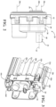
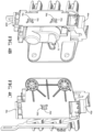
- the modular active grille shutter system 10 further includes an actuator pocket 18 in the frame 12.
- the actuator pocket 18 has an aperture 20 and a surface that from a vane connection side with side walls 22a, 22b, 22c extending perpendicularly therefrom.
- a plurality of alternate actuator output axes 28a, 28b, 28c is shown extending through the actuator pocket 18, which depending on the actuator design they represent different possible locations for alignment of an actuator 30 with three vanes 32a, 32b, 32c, shown in Fig. 3 . While certain drawings depict three vanes, other drawings depict five vanes. It is within the scope of this invention for the modular active grill shutter system 10 to have any number of vanes, however, in one preferred embodiment of the invention, shown in Fig. 1 there are three vanes.
- the actuator pocket 18 of the first base integrated end cap 14b includes datum cavities 34a, 34b, 34c, 34d, 34e, 34f.
- a housing 38 of the actuator 30 has datum features 33a, 33b, 33c, 33d, 33e, 33f extending from the housing 38 that align with and slide into the respective datum cavities 34a, 34b, 34c, 34d, 34e, 34f the housing 38 of the actuator 30 during assembly.
- the datum features 33a, 33b, 33c, 33d, 33e, 33f function to prevent rotation of the housing 38 of the actuator 30 during operation. This is particularly important since the actuator 30 is smaller to fit into a smaller actuator pocket 18, thereby pricing a modular active grille shutter system 10 that is smaller and can have fewer than three vanes.
- the smaller actuator 30 is possible in part to a stacked gear set 41 that is more compact, together with having a connector 31 formed on the housing 38 that has a connector axis 43 that is parallel to the plurality of output axis 28a, 28b, 28c, instead of being perpendicular to the plurality of output axis 28a, 28b, 28c.
- Within the housing 38 there is a printed circuit board 39 lead frame that is modified to extend connector wires 40 perpendicular to the printed circuit board 39, thereby allowing the connector 31 to have a connector axis that is parallel instead of perpendicular to the plurality of alternate output axes.
- the actuator pocket 18 further includes tunable retention features 29a, 29b, 29c, 29d, 29e, 29f, 29g, 29h, 29i formed on the surface of the actuator pocket 18.
- the tunable retention features 29a, 29b, 29c, 29d, 29e, 29f, 29g, 29h, 29i as shown are in the form of raised ribs, but can also be wedges, plateaus or other surface features that contact or engage an outer surface of the housing 38 of the actuator 30, to position the actuator at a desired depth or lateral position in the actuator pocket 18.
- the tunable retention features 29a, 29b, 29c, 29d, 29e, 29f, 29g, 29h, 29i can have different heights, thickness or locations depending on the desired position of the housing 38 in the actuator pocket 18.
- the actuator pocket 18 has one or more apertures 36a, 36b, 36c formed through the surface of the actuator pocket 18 that a respective one of the male tabs 35a, 35b, 35c snap into to hold the housing 38 within the actuator pocket 18.
- a degree of freedom means the directional variances that must be applied during assembly of the actuator to the conventional active grille shutter system or modular active grille shutter system.
- Conventional methods use at least two degrees of freedom as the actuator is moved toward the connecting position on the frame, the actuator must be tilted and/or shifted in several directions to ensure that the connector 31 is placed into an aperture on the frame and to align the actuator housing with fastener connection holes on the frame.
- the datum features 33a, 33b, 33c, 33d, 33e, 33f and clips 35a, 35b, 35c of the actuator 30 of the present invention provide an improvement over the conventional assembly methods by allowing assembly using what is referred to herein as a single degree of freedom assembly method.
- the single degree of freedom means that the actuator 30 is moved into engagement so the datum features 33a, 33b, 33c, 33d, 33e, 33f slide into respective datum cavities 34a, 34b, 34c, 34d, 34e, 34f to position the actuator 30 radially aligned within the actuator pocket 18, while simultaneously the male resilient tabs 35a, 35b, 35c of the actuator 30 snap into respective apertures 36a, 36b, 36c of the actuator pocket 18 to lock the actuator 30 into place and prevent the actuator 30 from moving laterally out of the actuator pocket 18.
- the actuator 30 is pushed in one direction into the actuator pocket 18 so that the rotatable output of the actuator 30 is aligned with the select alternate output axis 28a, 28b, 28c and simultaneously connected to the actuator pocket 18 using the male resilient tabs 35a, 35b, 35c.
- the one degree of freedom assembly is also made possible by the connector axis 43 of the connector 31 being parallel to the alternate output axis 28a, 28b, 28c instead of perpendicular.
- This parallel positioning eliminates the need to tilt or move the actuator 30 by additional degrees of freedom, since the connector axis 43 is parallel to the plurality of alternate output axes 28a, 28b, 28c, rather than perpendicular to the vane rotation axis as found in conventional actuators used with active grille shutter systems.
- the modular active grille shutter system 10 also includes the plurality of vanes or three vanes 32a, 32b, 32c shown in Fig. 1 , extending across the cooling aperture 16 of the frame 12 and rotatably connected to the frame 12 to rotate between an open position where air can move through the frame and a closed position where the vanes 32a 32b, 32c block air from moving through the cooling aperture 16.
- Each of the vanes 32a 32b, 32c are connected to the vane side 26 of the actuator pocket 18.
- vane 32b is in alignment with one of the plurality of alternate actuator output axes 28a, 28b, 28c and functions as a driven vane for the plurality of vanes 32a, 32b, 32c.
- vane 32b is the driven vane in the present embodiment of the invention it is within the scope of the invention for the driven vane to be any one of the plurality of vanes 32a, 32b, 32c.
- Another unique feature of the invention is the size of the housing 38 of the actuator 30, which has a width that is no greater than about two millimeters greater than the width of one of the plurality of vanes 32a, 32b, 32c.
- the vanes 32a, 32b, 32c each have a width of less than about 35mm and the width of the housing 38 is about 37mm or less.
- the modular active grille shutter system 10 further includes the actuator 30 housing 38 having a rotatable output 39 positioned in alignment with one of the plurality of alternate actuator output axes 28a, 28b, 28c of the actuator pocket 18.
- the axis of the rotatable output 39 of the actuator 30 can be located at different locations to match up with each of the alternate actuator output axes 28a, 28b, 28c. This is made possible using the stacked gear train 41, where the gears are stacked within the housing 38 rather than a linear layout. This also allows the housing 38 to be smaller and fit into the actuator pocket 18, which has a reduced size compared to conventional active grille systems.
- first universal rail 14a and the second universal rail 14c are connected between the first base integrated end cap 14b and the first base non-integrated end cap 14d.
- the first universal rail 14a and second universal rail 14c each form a side of the frame and each have a longitudinal axis with a pair of longitudinal channels 42a, 42b, 42c, 42d extending along the longitudinal axis of the first universal rail 14a and second universal rail 14c.
- Each of the longitudinal channels 42a, 42b, 42c, 42d have a deformable edge opening 44a, 44b, 44c, 44d (see Figs. 3 and 4a ).
- the longitudinal channels 42a, 42b, 42c, 42d connect to respective first end 46a and second end 46b on the first base integrated end cap 14b and respective first end 48a and second end 48b on the first base non-integrated end cap 14d.
- the secondary attachments in the form of center bars 50a, 50b of different lengths that extend across the opening of the frame and support the frame.
- the secondary attachments also include an auxiliary mount 52 or mounts used to connect other components such as, but not limited to sensors, microphones, speakers, lights, light detection and ranging modules (i.e.., LIDAR), wiring mounts or decorative panels such as grilles.
- the secondary attachments each have at least one clip 54a, 54b, 54c for connecting to a respective one of the longitudinal channels 42a, 42b, 42c, 42d of one of the first universal rail 14a or the second universal rail 14c.
- Each clip 54a, 54b, 54c has a pair of posts 56a, 56b, 56c, 56d, 56e, 56f, 56g disposed about a spike 58a, 58b, 58c, which are all slightly larger than the respective deformable edge opening 44a, 44b, 44c, 44d.
- the posts 56a, 56b, 56c, 56d, 56e, 56f, 56g slide into desired one of the longitudinal channels 42a, 42b, 42c, 42d and deform the respective deformable edge opening 44a, 44b, 44c, 44d to fix the secondary attachment to the longitudinal channel 42a, 42b, 42c, 42d.
- the present invention significantly simplifies and reduces the method of assembling the modular active grille shutter system 10.
- the frame, vanes and actuator are all formed separately and then connected together using hand assembly or a combination of automation and hand assembly.
- the actuator 30 contains a type of memory chip such as RAM or EPROM.
- a modular grille software is programmed onto the memory chip.
- the modular grille software contains a library of pre-encoded operational commands that are stored on the memory chip.
- the pre-encoded operational commands contain commands for different operational parameters for the actuator to operate the modular active grille shutter system based on various variables including grille size, number of shutters, temperature data, type of system of implementation (e.g., internal combustion engines, electric vehicles, etc.).
- the memory chip of the actuator is updated to build an operational program using the pre-encoded commands stored on the memory chip.
- the actuator operation will also be modular because the operational program is assembled using different pre-encoded commands already residing on the memory chip, thereby eliminating the need to separately write new operational software for each vehicle application.
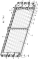
- a second and third embodiment showing a modular grille shutter system 100, 200 are shown.
- the modular grille shutter system 100, 200 utilizes the same components as shown in the modular grille shutter system 10 and builds off the same components to form a frame 112, 212 having an aperture 116, 216 that is larger than frame 12 and aperture 16.
- Modular grille shutter system 100 has six vanes, while modular grille shutter system 200 has eight vanes.
- Modular grille shutter system 100, 200 both include a second base integrated endcap 114 having a first end 146a and second end 146b. The second end 146b is connected to the first end 46a of the first base integrated end cap 14b.
- first universal frame rail 14a is attached to the second end 146b of the second base integrated end cap 114b and a second end 148b of the second base non-integrated end cap 114d to create a six vane system.
- the addition of the second based integrated end cap 114b and second base non-integrated end cap 114d increases the area of the frame 112 vertically to add three additional vanes 132a, 132b, 132c.
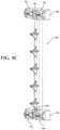
- Modular grille shutter system 200 shown in Fig. 7B is an eight vane system that further includes a third base integrated end cap extension 114e having a first end 246a connected to the second end 146b of the second base integrated end cap 114b.
- a third non-integrated end cap extension 114f having a first end 248a connected to the second end 148b of the second base non-integrated end cap 114d.
- the first universal frame rail 14a is connected at one end to a second end 246b of the first base integrated end cap extension 114e, and at a second end of the first universal frame rail 14a is connected to a second end 248b of the first non-integrated end cap extension 114f.
- Connected between the first base integrated end cap extension 114e and non-integrated end cap extension 114f are vanes 132d, 132e which complete a set of eight vanes for the modular grille shutter system 200.
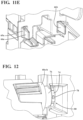
- FIGs. 11A, 11B , 11C, 11D , 11E all the connection details of the first end 46a, 146a, 246a, 48a, 148a, 248a and second end 46b, 146b, 246b, 48b, 148b, 248b of the first base integrated end cap 14b, second base integrated end cap 114b, first base integrated end cap extension 114e, first base non-integrated end cap 14d, second base non-integrated end cap 114d and first non-integrated end cap extension 114f are now shown and described.
- the first end 46a, 146a, 246a, 48a, 148a, 248a include a male tongue 64a, 64b and hook 66a, 66b on each side.
- the second end 46b, 146b, 246b, 48b, 148b, 248b have a female connection groove 60a, 60b on each side, each having a snap aperture 62a, 62b with a tab 65a, 65b extending from an edge of the snap aperture 62a, 62b.
- the male tongue 64a, 64b slides into the female connection groove 60a, 60b and the hook 66a, 66b slides through the snap aperture 62a, 62b and snaps into place on the respective tab 65a, 65b.
- first end 46a, 146a, 246a, 48a, 148a, 248a and second end 46b, 146b, 246b, 48b, 148b, 248b allows for vertically assembling a modular grille shutter system of virtually any height without using fasteners, adhesives, or any additional connections.
- each vane 32a, 32b, 32c, 132a, 132b, 132c, 132d, 132e are each held separately by a vane retainer 68a, 68b, 68c, 68d, 68e, 68f, 68g, 68h rotatably connected to one of the first base integrated end cap 14b, second base integrated end cap 114b, first base integrated end cap extension 114e.
- a vane retainer 68a, 68b, 68c, 68d, 68e, 68f, 68g, 68h rotatably connected to one of the first base integrated end cap 14b, second base integrated end cap 114b, first base integrated end cap extension 114e.
- each vane 32a, 32b, 32c, 132a, 132b, 132c, 132d, 132e is slides onto and rotates about a respective post 69a, 69b, 69c, 69d, 69e, 69f, 69g, 69h formed on a respective one of the first base non-integrated end cap 14d, second base non-integrated end cap 114d and first non-integrated end cap extension 114f.
- the details of the vane retainer and posts are described in United States Patent Application Publication No. US2020/0346538A1 titled "IN MOLD ASSEMBLY FOR ACTIVE GRILLE SHUTTER SYSTEM" filed March 23, 2020 ; the entire specification and drawings of which are hereby expressly incorporated by reference.
- each vane retainer 68a, 68b, 68c, 68d, 68e, 68f, 68g, 68h include a vane connection side 70 and an end cap connection side 72 rotatably fixed to the respective one of the first base integrated end cap 14b, second base integrated end cap 114b, first base integrated end cap extension 114e.
- Each vane retainer 68a, 68b, 68c, 68d, 68e, 68f, 68g, 68h can optionally include a post 74 that rotatably extends into a collar 76 formed on one of the first base integrated end cap 14b, second base integrated end cap 114b, first base integrated end cap extension 114e.
- Each post 74 has a stop 78 that extends from an outer radius of the post 74 and is positioned in a collar groove 80 formed in the collar 76 that allows the vane retainer 68a, 68b, 68c, 68d, 68e, 68f, 68g, 68h, stop 78 and the post 74 to rotate, while preventing the post 74 from sliding out of the collar 76.
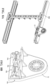
- a multi-piece link arm 82 Since the modular grille shutter system 10, 100, 200 can have different vertical heights it is necessary to transfer operational force from the actuator 30 to all of the vanes 32a, 32b, 32c, 132a, 132b, 132c, 132d, 132e, which is accomplished using the vane retainer 68a, 68,b, 68c, 68d, 68e, 68f, 68g, 68h and the multi-piece link arm 82.
- vane 32b is what is connected to the rotatable output 39 through the vane retainer 68b using a direct connection.
- each vane retainer 68a, 68b, 68c, 68d, 68e, 68f has a link pin 84a, 84b, 84c, 84d, 84e, 84f formed on each vane connection side 70.
- the multi-piece link arm 82 as shown has a first piece 85 and second piece 86 connected together by a link connection 87.
- the first piece 85 connects rotatably to link pin 84a, 84b, 84c, while second piece 86 connects rotatably to link pin 84d, 84e, 84f.
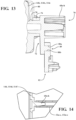
- Each link pin 84a, 84b, 84c, 84d, 84e, 84f of vane retainer 68a, 68b, 68c, 68d, 68e, 68f has a reverse draft 88a, 88b (shown in Fig. 13 ) formed on the outer diameter that extends through a link aperture 89 formed on the multi-piece link arm 82.
- the reverse draft 88a, 88b is formed during the molding process and rotatably and securely connects the multi-piece link arm 82 to each vane retainer 68a, 68b, 68c, 68d, 68e, 68f to they cannot easily be separated and do not rely on other connection means such as retainers or adhesives.
- the first piece 85 and second piece 86 are connected together using the link connection 87.
- additional link connections similar to the link connection 87 are used.
- the link connection 87 as shown includes a link aperture 90 formed on the first piece 85 at a first end and has a tab 91 extending from an edge surface of the link aperture 90.
- the first piece 85 also has a second end with two alignment posts 92a, 92b and a single flexible tang 93 extending from the surface.
- the second piece 86 as shown includes a link aperture 94 formed on the second piece 86 at a first end and has a tab 95 extending from an edge surface of the link aperture 94.
- the second piece 86 also has a second end with two alignment posts 96a, 96b and a single flexible tang 97 extending from the surface.
- the first end of the second piece 86 engages the second end of the first piece 85 such that the two alignment posts 92a, 92b and flexible tang 93 slide through the link aperture 94 of the second piece 86, and the flexible tang 93 bends and locks to the tab 95 extending from the edge surface, to lock the first piece 85 to the second piece 86.
- the aperture 90 and tab 91 of the first piece 85 can be used to connect additional pieces on the other side of the first piece 85, while the two alignment posts 96a, 96b and single flexible tang 97 can be used to connect additional pieces to the second side of the second piece 86.
Landscapes
- Engineering & Computer Science (AREA)
- Chemical & Material Sciences (AREA)
- Combustion & Propulsion (AREA)
- Mechanical Engineering (AREA)
- Transportation (AREA)
- General Engineering & Computer Science (AREA)
- Cooling, Air Intake And Gas Exhaust, And Fuel Tank Arrangements In Propulsion Units (AREA)
Claims (14)
- Modulares aktives Kühlergrill-Verschlusssystem (10; 100; 200), das aufweist:ein aktives Kühlergrill-Verschlusssystem (10; 100; 200) mit einem Rahmen (12), der in einem Kühlkanal (16) einer Versorgungsquelle für ein Fahrzeug angeordnet ist, wobei der Rahmen (12) eine integrierte Basisendkappe (14b) und eine nicht integrierte Basisendkappe (14d) aufweist, wobei die integrierte Basisendkappe (14b) eine Aktuatortasche (18) mit einer Anzahl von alternierenden Aktuatorausgangsachsen (28a, 28b, 28c) aufweist, die innerhalb der Aktuatortasche (18) angeordnet sind;eine Anzahl von Flügeln (32a, 32b, 32c), die drehbar an einem ersten Ende mit der Basisendkappe verbunden sind und sich über den Kühlkanal (16) erstrecken und an einem zweiten Ende mit der nicht integrierten Basisendkappe (14d) verbunden sind, wobei die Anzahl von Flügeln (32a, 32b, 32c) zwischen einer offenen Position und einer geschlossenen Position rotieren; undeinen Aktuator (30) mit einem Gehäuse (38) mit einem drehbaren Ausgang (39), der in einer in dem Gehäuse (38) ausgebildeten Öffnung positioniert ist, wobei die Öffnung und der drehbare Ausgang (39) an einer Stelle ausgebildet sind, die mit einer der mehreren alternativen Ausgangsachsen (28a, 28b, 28c) ausrichtbar ist, wobei der Aktuator (30) betriebsmäßig mit den mehreren Flügeln (32a, 32b, 32c) verbunden ist, so dass eine Drehung des Aktuatorausgangs die mehreren Flügel (32a, 32b, 32c) dreht.
- Modulares aktives Kühlergrill-Verschlusssystem (10; 100; 200) nach Anspruch 1, das außerdem Folgendes umfasst:
einen Verbinder (31), der an dem Aktuatorgehäuse (38) ausgebildet ist, wobei der Verbinder (31) eine Achse des Verbinders (31) aufweist, die parallel zu der Anzahl von alternativen Ausgangsachsen (28a, 28b, 28c) ist. - Modulares aktives Kühlergrill-Verschlusssystem (100; 200) nach Anspruch 1, das ferner aufweist:die integrierte Basisendkappe (14b) des Rahmens (112; 212), die eine erste integrierte Basisendkappe (14b) ist, die ein erstes Ende (46a) mit einer Aufnahme-Verbindungsnut (60a, 60b) und mindestens einer Schnappöffnung (62a, 62b) und ein zweites Ende (46b) mit einer Einsteckzunge (64a, 64b) und mindestens einem Haken (66a, 66b) aufweist;eine zweite integrierte Basisendkappe (114b) des Rahmens (112; 212), die ein erstes Ende (146a) mit einer Aufnahme-Verbindungsnot (60a, 60b) und mindestens einer Schnappöffnung (62a, 62b) und ein zweites Ende (146b) mit einer Einsteckzunge (64a, 64b) und mindestens einem Haken (66a, 66b) aufweist, wobei das erste Ende (146a) der zweiten integrierten Basisendkappe (114b) mit dem zweiten Ende (46b) der ersten integrierten Basisendkappe (14b) so verbunden ist, dass die Aufnahme-Verbindungsnut (60a, 60b) der zweiten integrierten Basisendkappe (114b) die Einsteckzunge (64a, 64b) des zweiten Endes (46b) der ersten integrierten Basisendkappe (14b) aufnimmt und der mindestens eine Haken (66a, 66b) der ersten integrierten Basisendkappe (14b) in die mindestens eine Schnappöffnung (62a, 62b) der zweiten integrierten Basisendkappe (114b) einrastet;wobei die nicht integrierte Basisendkappe (14d) des Rahmens (112; 212) eine erste nicht integrierte Basisendkappe (14d) ist, die ein erstes Ende (48a) mit einer Aufnahme-Verbindungsnut (60a, 60b) und mindestens einer Schnappöffnung (62a, 62b) und ein zweites Ende (48b) mit einer Einsteckzunge (64a, 64b) und mindestens einem Haken (66a, 66b) aufweist;eine zweite nicht integrierte Basisendkappe (114d) des Rahmens (112; 212), die ein erstes Ende (148a) mit einer Aufnahme-Verbindungsnut (60a, 60b) und mindestens einer Schnappöffnung (62a, 62b) und ein zweites Ende (148b) mit einer Einsteckzunge (64a, 64b) und mindestens einem Haken (66a, 66b) aufweist, wobei das erste Ende (148a) der zweiten integrierten Basisendkappe (114b) mit dem zweiten Ende (48b) der ersten nicht integrierten Basisendkappe (14d) verbunden ist, so dass die Aufnahme-Verbindungsnut (60a, 60b) der zweiten nicht integrierten Basisendkappe (114d) die Einsteckzunge (64a, 64b) des zweiten Endes (48b) der ersten nicht integrierten Basisendkappe (14d) aufnimmt und der mindestens eine Haken (66a, 66b) der ersten nicht integrierten Basisendkappe (14d) in die mindestens eine Schnappöffnung (62a, 62b) der zweiten nicht integrierten Basisendkappe (114d) einrastet;eine erste Universalschiene (14a), die an einem ersten Ende mit der ersten integrierten Basisendkappe (14b) und an einem zweiten Ende mit der ersten nicht integrierten Basisendkappe (14d) verbunden ist;eine zweite Universalschiene (14c), die an einem ersten Ende mit der zweiten integrierten Basisendkappe (114b) und an einem zweiten Ende mit der zweiten nicht integrierten Basisendkappe (114d) verbunden ist, wobei die erste Universalschiene (14a) und die zweite Universalschiene (14c) jeweils eine Seite des Rahmens (112; 212) bilden;die Anzahl von Flügeln (32a, 32b, 32c, 132a, 132b, 132c, 132d, 132e), die jeweils an einem ersten Ende mit einer der ersten integrierten Basisendkappe (14b) oder der zweiten integrierten Basisendkappe (114b) und an einem zweiten Ende mit einer der ersten nicht integrierten Basisendkappe (14d) oder der zweiten nicht integrierten Basisendkappe (114d) drehbar verbunden sind, so dass die Anzahl von Flügeln (32a, 32b, 32c, 132a, 132b, 132c, 132d, 132e) sich über den Kühlkanal erstrecken und sich zwischen einer offenen und einer geschlossenen Position drehen.
- Modulares Kühlergrill-Verschlusssystem (100; 200) nach Anspruch 3, das außerdem Folgendes umfasst:wobei die erste integrierte Basisendkappe (14b) ferner eine Anzahl von Flügelhaltern (68a, 68b, 68c, 68d, 68e, 68f, 68g, 68h) aufweist, die jeweils eine Flügelverbindungsseite (70) zur Aufnahme des ersten Endes eines der Anzahl von Flügeln (32a, 32b, 32c, 132a, 132b, 132c, 132d, 132e) und eine Endkappenverbindungsseite (72) aufweisen, die drehbar an der integrierten Basisendkappe (14b) befestigt ist, wobei die Endkappenverbindungsseite (72) einen Zapfen (74) enthält, der sich drehbar in einen Kragen (76) erstreckt, der an der ersten integrierten Basisendkappe (14b) ausgebildet ist, wobei der Zapfen (74) einen Anschlag (78) enthält, der sich von einem äußeren Radius des Zapfens (74) erstreckt, wobei der Anschlag (78) in einer Kragennut (80) positioniert ist, die in dem Kragen (76) ausgebildet ist, die es dem Anschlag (78) und dem Zapfen (74) ermöglicht, sich zu drehen, während der Zapfen (74) daran gehindert wird, aus dem Kragen (76) herauszugleiten;wobei die zweite basisintegrierte Endkappe (114b) ferner eine Anzahl von Flügelhaltern (68a, 68b, 68c, 68d, 68e, 68f, 68g, 68h) aufweist, die jeweils eine Flügelverbindungsseite (70) zur Aufnahme des Endes einer anderen der Anzahl von Flügeln (32a, 32b, 32c, 132a, 132b, 132c, 132d, 132e) und eine Endkappenverbindungsseite (72) aufweisen, die drehbar an der basisintegrierten Endkappe (114b) befestigt ist, wobei die Flügelverbindungsseite (70) einen Zapfen (74) aufweist, der sich drehbar in einen Kragen (76) erstreckt, der an der ersten integrierten Basisendkappe (14b) ausgebildet ist, wobei der Zapfen (74) einen Anschlag (78) aufweist, der sich von einem äußeren Radius des Zapfens (74) erstreckt, wobei der Anschlag (78) in einer Kragennut (80) positioniert ist, die in dem Kragen (76) ausgebildet ist, die es dem Anschlag (78) und dem Zapfen (74) ermöglicht, sich zu drehen, während der Zapfen (74) daran gehindert wird, aus dem Kragen (76) herauszugleiten; undeinen mehrteiligen Verbindungsarm (82), der mit jedem der Anzahl von Flügelhaltern (68a, 68b, 68c, 68d, 68e, 68f, 68g, 68h) verbunden ist und sich zwischen diesen erstreckt und drehbar mit jedem Verbindungsstift (84a, 84b, 84c, 84d, 84e, 84f) verbunden ist, der auf jeder Flügelverbindungsseite (70) der Anzahl von Flügelhaltern (68a, 68b, 68c, 68d, 68e, 68f, 68g, 68h) der ersten integrierten Basisendkappe (14b) und der zweiten integrierten Basisendkappe (114b) ausgebildet ist.
- Modulares aktives Kühlergrill-Verschlusssystem (100; 200) nach Anspruch 4, wobei der Verbindungsstift (84a, 84b, 84c, 84d, 84e, 84f) jedes der mehreren Flügelhalter (68a, 68b, 68c, 68d, 68e, 68f, 68g, 68h) einen am Außendurchmesser ausgebildeten Gegenzug (88a, 88b) aufweist, der sich durch eine von mehreren Verbindungsöffnungen (90) (89) erstreckt, die an dem mehrteiligen Verbindungsarm (82) ausgebildet sind.
- Modulares Kühlergrill-Verschlusssystem (100; 200) nach Anspruch 4, wobei der mehrteilige Verbindungsarm (82) weiterhin umfasst:ein erstes Stück (85) mit einem ersten Ende, das eine Verbindungsöffnung (90) mit einer Lasche (91) aufweist, die sich von einer Randfläche der Verbindungsöffnung (90) aus erstreckt, und einem zweiten Ende, das zwei Ausrichtungszapfen (92a, 92b) und eine einzelne flexible Lasche (93) aufweist, die sich von einer Fläche aus erstreckt; undein zweites Stück (86) mit einem ersten Ende, das eine Verbindungsöffnung (94) mit einer Lasche (95) aufweist, die sich von einer Randfläche der Verbindungsöffnung (90) aus erstreckt, und einem zweiten Ende, das zwei Ausrichtungszapfen (96a, 96b) und einen einzelnen flexiblen Zapfen (97) aufweist, der sich von einer Oberfläche aus erstreckt, wobei das erste Ende des zweiten Teils (86) in das zweite Ende des ersten Teils (85) eingreift, so dass die beiden Ausrichtungszapfen (92a, 92b) und der flexible Zapfen (93) durch die Verbindungsöffnung (94) des ersten Teils (85) gleiten und der flexible Zapfen (93) sich biegt und an der Lasche (95) einrastet, die sich von der Randfläche erstreckt, um das erste Teil (85) mit dem zweiten Teil (86) zu verriegeln.
- Modulares Kühlergrill-Verschlusssystem (10; 100; 200) nach Anspruch 1 oder 3, das außerdem Folgendes umfasst:eine oder mehrere Öffnungen (36a, 36b, 36c), die auf der Oberfläche der Aktuatortasche (18) ausgebildet sind; undeine oder mehrere elastische Einstecklaschen (35a, 35b, 35c), die sich von dem Gehäuse (38) des Betätigungselements (30) erstrecken, um in eine entsprechende der einen oder mehreren Öffnungen (36a, 36b, 36c) der Aktuatortasche (18) einzurasten.
- Modulares Kühlergrill-Verschlusssystem (10; 100; 200) nach Anspruch 1 oder 3, das außerdem Folgendes umfasst:ein oder mehrere Bezugsmerkmale (33a, 33b, 33c, 33d, 33e, 33f), die sich vom Gehäuse (38) des Aktuators (30) aus erstrecken; undeinen oder mehrere Bezugshohlräume (34a, 34b, 34c, 34d, 34e, 34f), die in der Aktuatortasche (18) der integrierten Basisendkappe (14b) ausgebildet sind, um ein entsprechendes des einen oder der mehreren Bezugsmerkmale (33a, 33b, 33c, 33d, 33e, 33f) aufzunehmen, um das Gehäuse (38) des Aktuators (30) während der Montage des Aktuators (30) an der Aktuatortasche (18) auszurichten und eine Drehung des Gehäuses (38) des Aktuators (30) während des Betriebs zu verhindern.
- Modulares Kühlergrill-Verschlusssystem (10; 100; 200) nach Anspruch 1 oder 3, das ferner ein oder mehrere abstimmbare Rückhalteelemente (29a, 29b, 29c, 29d, 29e, 29f, 29g, 29h, 29i) umfasst, die auf der Oberfläche der Aktuatortasche (18) ausgebildet sind und in eine Außenfläche des Gehäuses (38) des Aktuators (30) eingreifen, wenn sie mit der Aktuatortasche (18) verbunden sind, wobei das eine oder die mehreren abstimmbaren Rückhaltemerkmale (29a, 29b, 29c, 29d, 29e, 29f, 29g, 29h, 29i) das Gehäuse (38) daran hindern, sich innerhalb der Aktuatortasche (18) zu drehen, indem sie an der Außenfläche des Gehäuses (38) des Aktuators (30) an einer oder mehreren Spaltstellen zwischen dem Aktuatorgehäuse (38) und einer Oberfläche der Aktuatortasche (18) angreifen.
- Modulares Grillverschlusssystem (10; 100; 200) nach Anspruch 1 oder 3, wobei das Gehäuse (38) des Aktuators (30) eine Breite aufweist, die nicht größer als etwa zwei Millimeter größer ist als die Breite einer der mehreren Flügel (32a, 32b, 32c).
- Modulares Grillverschlusssystem (10; 100; 200) nach Anspruch 1, wobei der Rahmen (12) weiterhin umfasst:eine erste Universalschiene (14a) und eine zweite Universalschiene (14c), die jeweils an einem ersten Ende mit der Basisendkappe (14a) und an einem zweiten Ende mit der nichtintegrierten Basisendkappe (14d) verbunden sind, wobei die erste Universalschiene (14a) und die zweite Universalschiene (14c) jeweils eine Seite des Rahmens (12) bilden, die eine Längsachse mit einem Längskanal (42a, 42b, 42c, 42d) aufweist, der sich entlang der Längsachse erstreckt, wobei der Längskanal (42a, 42b, 42c, 42d) eine verformbare Randöffnung (44a, 44b, 44c, 44d) aufweist; undeine zweite Befestigung (50a, 50b; 52) mit mindestens einer Halterung (54a, 54b, 54c) zur Verbindung mit dem Längskanal (42a, 42b, 42c, 42d) einer der ersten Universalschiene (14a) oder der zweiten Universalschiene (14c), wobei die mindestens eine Halterung (54a, 54b, 54c) mindestens einen Zapfen (56a, 56b, 56c, 56d, 56e, 56f, 56a, 56b, 56c, 56d, 56e, 56f, 56g) aufweist, der größer ist als die verformbare Randöffnung (44a, 44b, 44c, 44d), wobei der mindestens eine Zapfen (56a, 56b, 56c, 56d, 56e, 56f, 56g) in den Längskanal (42a, 42b, 42c, 42d) gleitet und die verformbare Randöffnung (44a, 44b, 44c, 44d) verformt, um die sekundäre Befestigung (50a, 50b, 52) an dem Längskanal (42a, 42b, 42c, 42d) zu befestigen.
- Modulares Grillverschlusssystem (100; 200) nach Anspruch 3, wobei der Rahmen (112; 212) weiterhin umfasst:wobei die erste Universalschiene (14a) und die zweite Universalschiene (14c) jeweils eine Längsachse mit einem Längskanal (42a, 42b, 42c, 42d) aufweisen, der sich entlang der Längsachse erstreckt, wobei der Längskanal (42a, 42b, 42c, 42d) eine verformbare Randöffnung (44a, 44b, 44c, 44d) aufweist; undeine zweite Befestigung (50a, 50b; 52) mit mindestens einer Halterung (54a, 54b, 54c) zur Verbindung mit dem Längskanal (42a, 42b, 42c, 42d) einer der ersten Universalschiene (14a) oder der zweiten Universalschiene (14c), wobei die mindestens eine Halterung (54a, 54b, 54c) mindestens einen Zapfen (56a, 56b, 56c, 56d, 56e, 56f, 56a, 56b, 56c, 56d, 56e, 56f, 56g) aufweist, der größer ist als die verformbare Randöffnung (44a, 44b, 44c, 44d), wobei der mindestens eine Stift (56a, 56b, 56c, 56d, 56e, 56f, 56g) in den Längskanal (42a, 42b, 42c, 42d) gleitet und die verformbare Randöffnung (44a, 44b, 44c, 44d) verformt, um die sekundäre Befestigung (50a, 50b, 52) an dem Längskanal (42a, 42b, 42c, 42d) zu befestigen.
- Modulares Grillverschlusssystem (10; 100; 200) nach Anspruch 11 oder 12, wobei die sekundäre Befestigung eine Hilfsbefestigung (52) ist, die zur Befestigung einer sekundären Komponente verwendet wird.
- Modulares Grillverschlusssystem (10; 100; 200) nach Anspruch 13, wobei die sekundäre Befestigung eine Mittelstange (50a, 50b) ist, die sich über eine Öffnung des Rahmens (12) erstreckt, um den Rahmen (12) zu stützen.
Priority Applications (1)
| Application Number | Priority Date | Filing Date | Title |
|---|---|---|---|
| EP23207859.2A EP4296103A3 (de) | 2019-12-27 | 2020-12-23 | Aktuator für modulare aero-vorrichtung und modulares aktives gitterverschlusssystem mit einer reduzierten anzahl von schaufeln |
Applications Claiming Priority (2)
| Application Number | Priority Date | Filing Date | Title |
|---|---|---|---|
| US201962954157P | 2019-12-27 | 2019-12-27 | |
| PCT/US2020/066803 WO2021133890A2 (en) | 2019-12-27 | 2020-12-23 | Modular aero device actuator and a modular active grille shutter system having a reduced number of vanes |
Related Child Applications (2)
| Application Number | Title | Priority Date | Filing Date |
|---|---|---|---|
| EP23207859.2A Division-Into EP4296103A3 (de) | 2019-12-27 | 2020-12-23 | Aktuator für modulare aero-vorrichtung und modulares aktives gitterverschlusssystem mit einer reduzierten anzahl von schaufeln |
| EP23207859.2A Division EP4296103A3 (de) | 2019-12-27 | 2020-12-23 | Aktuator für modulare aero-vorrichtung und modulares aktives gitterverschlusssystem mit einer reduzierten anzahl von schaufeln |
Publications (2)
| Publication Number | Publication Date |
|---|---|
| EP4054873A2 EP4054873A2 (de) | 2022-09-14 |
| EP4054873B1 true EP4054873B1 (de) | 2023-12-20 |
Family
ID=74191974
Family Applications (2)
| Application Number | Title | Priority Date | Filing Date |
|---|---|---|---|
| EP23207859.2A Withdrawn EP4296103A3 (de) | 2019-12-27 | 2020-12-23 | Aktuator für modulare aero-vorrichtung und modulares aktives gitterverschlusssystem mit einer reduzierten anzahl von schaufeln |
| EP20842889.6A Active EP4054873B1 (de) | 2019-12-27 | 2020-12-23 | Modularer stellantrieb für flugzeugvorrichtungen und modulares aktives gitterverschlusssystem mit einer reduzierten anzahl von lamellen |
Family Applications Before (1)
| Application Number | Title | Priority Date | Filing Date |
|---|---|---|---|
| EP23207859.2A Withdrawn EP4296103A3 (de) | 2019-12-27 | 2020-12-23 | Aktuator für modulare aero-vorrichtung und modulares aktives gitterverschlusssystem mit einer reduzierten anzahl von schaufeln |
Country Status (5)
| Country | Link |
|---|---|
| US (1) | US12570139B2 (de) |
| EP (2) | EP4296103A3 (de) |
| KR (1) | KR20220116035A (de) |
| CN (1) | CN114845896A (de) |
| WO (1) | WO2021133890A2 (de) |
Families Citing this family (6)
| Publication number | Priority date | Publication date | Assignee | Title |
|---|---|---|---|---|
| US11845331B2 (en) | 2022-03-03 | 2023-12-19 | Valeo Systemes Thermiques | Air flow control device for a front face module of a motor vehicle |
| CN115465093B (zh) * | 2022-09-20 | 2024-07-19 | 重庆长安汽车股份有限公司 | 一种集成智能进气格栅的前端模块结构 |
| FR3149549B1 (fr) | 2023-06-06 | 2025-10-31 | Renault Sas | Dispositif de gestion d’entrée d’air pour véhicule automobile |
| CN117068038A (zh) * | 2023-08-18 | 2023-11-17 | 深蓝汽车科技有限公司 | 一种发光叶片、主动进气格栅及汽车 |
| EP4523937A1 (de) * | 2023-09-14 | 2025-03-19 | Motherson Innovations Company Ltd. | Gitterverschlussanordnung |
| FR3161608A1 (fr) * | 2024-04-24 | 2025-10-31 | Stellantis Auto Sas | Dispositif de régulation pour entrée d’air pilotée de véhicule automobile |
Citations (2)
| Publication number | Priority date | Publication date | Assignee | Title |
|---|---|---|---|---|
| DE102017107384B4 (de) * | 2017-04-06 | 2019-03-07 | Otto Altmann | Fahrzeugdiagnosesystem für Frontkühleinheiten, Kraftfahrzeug mit einem solchen Fahrzeugdiagnosesystem und Fahrzeugdiagnoseverfahren für Frontkühleinheiten |
| DE102017105568B4 (de) * | 2017-03-15 | 2021-02-11 | Geiger Automotive Gmbh | Modulares Luftklappensystem |
Family Cites Families (15)
| Publication number | Priority date | Publication date | Assignee | Title |
|---|---|---|---|---|
| DE102009020352A1 (de) * | 2009-05-07 | 2010-11-11 | Dr. Ing. H.C. F. Porsche Aktiengesellschaft | Aufnahmevorrichtung für ein Kühlluftklappenmodul in einer Bugverkleidung eines Kraftfahrzeugs |
| CA2758502C (en) * | 2010-11-16 | 2018-09-25 | Magna International Inc. | Bracket - active grille and actuator |
| KR101272930B1 (ko) * | 2011-12-08 | 2013-06-11 | 현대자동차주식회사 | 차량용 액티브 에어플랩 장치 |
| NL2009105C2 (nl) * | 2012-07-02 | 2014-01-06 | Mci Mirror Controls Int Nl Bv | Verstelsysteem, primaire versteleenheid en secundaire versteleenheid. |
| KR101428203B1 (ko) * | 2012-11-05 | 2014-08-07 | 현대자동차주식회사 | 차량용 액티브 에어플랩 장치 및 고장 진단 방법 |
| US9533565B2 (en) * | 2013-02-05 | 2017-01-03 | Montaplast of North America, Inc. | Active grille shutter assembly |
| DE102015109702A1 (de) * | 2015-06-17 | 2016-12-22 | Hbpo Gmbh | Verschlussvorrichtung zum Verschließen eines funktionswesentlichen Bauteils eines Fahrzeuges |
| JP6318120B2 (ja) * | 2015-06-30 | 2018-04-25 | 株式会社ファルテック | グリルシャッタユニット |
| FR3047205B1 (fr) * | 2016-02-03 | 2018-01-26 | Valeo Systemes Thermiques | Dispositif d'obturation d'entree d'air de face avant de vehicule automobile et son procede de fabrication |
| US10960754B2 (en) | 2016-08-12 | 2021-03-30 | Magna Exteriors, Inc. | Mold assembly for active grille shutter system |
| CA3030990A1 (en) * | 2016-08-12 | 2018-02-15 | Braendon LINDBERG | Active grille, scalable design |
| FR3056464B1 (fr) | 2016-09-28 | 2019-06-07 | Valeo Systemes Thermiques | Dispositif de controle d'entree d'air pour un module de face avant d'un vehicule automobile |
| FR3069494B1 (fr) | 2017-07-28 | 2019-08-02 | Valeo Systemes Thermiques | Dispositif d'obturation d'entree d'air de vehicule automobile et procede de fabrication d'un tel dispositif d'obturation |
| CN109080445A (zh) * | 2018-08-10 | 2018-12-25 | 吉利汽车研究院(宁波)有限公司 | 附加式可变主动进气格栅和汽车 |
| JP2021024324A (ja) | 2019-07-31 | 2021-02-22 | 株式会社デンソー | シャッター装置 |
-
2020
- 2020-12-23 EP EP23207859.2A patent/EP4296103A3/de not_active Withdrawn
- 2020-12-23 US US17/783,044 patent/US12570139B2/en active Active
- 2020-12-23 CN CN202080089619.8A patent/CN114845896A/zh active Pending
- 2020-12-23 KR KR1020227025365A patent/KR20220116035A/ko not_active Ceased
- 2020-12-23 WO PCT/US2020/066803 patent/WO2021133890A2/en not_active Ceased
- 2020-12-23 EP EP20842889.6A patent/EP4054873B1/de active Active
Patent Citations (2)
| Publication number | Priority date | Publication date | Assignee | Title |
|---|---|---|---|---|
| DE102017105568B4 (de) * | 2017-03-15 | 2021-02-11 | Geiger Automotive Gmbh | Modulares Luftklappensystem |
| DE102017107384B4 (de) * | 2017-04-06 | 2019-03-07 | Otto Altmann | Fahrzeugdiagnosesystem für Frontkühleinheiten, Kraftfahrzeug mit einem solchen Fahrzeugdiagnosesystem und Fahrzeugdiagnoseverfahren für Frontkühleinheiten |
Also Published As
| Publication number | Publication date |
|---|---|
| CN114845896A (zh) | 2022-08-02 |
| US12570139B2 (en) | 2026-03-10 |
| WO2021133890A3 (en) | 2021-07-29 |
| EP4054873A2 (de) | 2022-09-14 |
| WO2021133890A2 (en) | 2021-07-01 |
| EP4296103A2 (de) | 2023-12-27 |
| KR20220116035A (ko) | 2022-08-19 |
| EP4296103A3 (de) | 2024-07-31 |
| CA3161480A1 (en) | 2021-07-01 |
| US20230010412A1 (en) | 2023-01-12 |
Similar Documents
| Publication | Publication Date | Title |
|---|---|---|
| EP4054873B1 (de) | Modularer stellantrieb für flugzeugvorrichtungen und modulares aktives gitterverschlusssystem mit einer reduzierten anzahl von lamellen | |
| KR102089601B1 (ko) | 액티브 그릴 셔터 다중 부품 모듈형 프레임 | |
| CN109564024B (zh) | 主动格栅的可扩展设计 | |
| US6903473B2 (en) | Motor having connector housing | |
| EP1793289A1 (de) | Vorrichtung zur Steuerung eines Roboters und Robotersystem | |
| US6837261B2 (en) | Control valve assembly of valve assembly-injection-molded control valves or modules | |
| US20090020309A1 (en) | Wire management cover and system | |
| CN110958955B (zh) | 用于关闭机动车辆进气口的装置和制造该关闭装置的方法 | |
| KR20170121068A (ko) | 액티브 그릴 셔터 다중 부품 모듈형 프레임 | |
| CN108263487A (zh) | 宽松分层装配部件和车辆前端组装策略 | |
| KR20180025990A (ko) | 모듈형 커넥터 | |
| EP4484194A1 (de) | Kühlmodul | |
| US7129595B2 (en) | Hybrid electro-mechanical vehicular transmission having multiple modular motor/generators assembled from like components | |
| JP3108072U (ja) | エアバッグ制御装置用メタル・ハウジング | |
| CN114786983A (zh) | 用于机动车辆的冷却模块 | |
| CA3161480C (en) | Modular aero device actuator and a modular active grille shutter system having a reduced number of vanes | |
| CA3102589C (en) | Serviceable actuation system for active grille shutter | |
| EP4484811A1 (de) | Kühlmodulventil und kühlmodul | |
| CN211364250U (zh) | 用于机动车辆的前部面的空气入口的阻塞装置 | |
| JP3961810B2 (ja) | 外部コネクタ、車両用アクチュエータ装置及び車両用エアコン装置 | |
| CN119255928A (zh) | 用于控制机动车辆的气流循环的装置用的盒以及用于这种盒的遮板 | |
| KR100827959B1 (ko) | 자동차의 헤드 라이닝 조립체 | |
| EP4475523B1 (de) | Sichtkamera für ein fahrer-überwachungssystem und verfahren zur montage einer sichtkamera | |
| US20200139806A1 (en) | Shutter device | |
| JPH09229226A (ja) | 電磁弁マニホールド及び電磁弁マニホールド用配線カバー |
Legal Events
| Date | Code | Title | Description |
|---|---|---|---|
| STAA | Information on the status of an ep patent application or granted ep patent |
Free format text: STATUS: UNKNOWN |
|
| STAA | Information on the status of an ep patent application or granted ep patent |
Free format text: STATUS: THE INTERNATIONAL PUBLICATION HAS BEEN MADE |
|
| PUAI | Public reference made under article 153(3) epc to a published international application that has entered the european phase |
Free format text: ORIGINAL CODE: 0009012 |
|
| STAA | Information on the status of an ep patent application or granted ep patent |
Free format text: STATUS: REQUEST FOR EXAMINATION WAS MADE |
|
| 17P | Request for examination filed |
Effective date: 20220608 |
|
| AK | Designated contracting states |
Kind code of ref document: A2 Designated state(s): AL AT BE BG CH CY CZ DE DK EE ES FI FR GB GR HR HU IE IS IT LI LT LU LV MC MK MT NL NO PL PT RO RS SE SI SK SM TR |
|
| DAV | Request for validation of the european patent (deleted) | ||
| DAX | Request for extension of the european patent (deleted) | ||
| P01 | Opt-out of the competence of the unified patent court (upc) registered |
Effective date: 20230517 |
|
| GRAP | Despatch of communication of intention to grant a patent |
Free format text: ORIGINAL CODE: EPIDOSNIGR1 |
|
| STAA | Information on the status of an ep patent application or granted ep patent |
Free format text: STATUS: GRANT OF PATENT IS INTENDED |
|
| INTG | Intention to grant announced |
Effective date: 20230720 |
|
| GRAS | Grant fee paid |
Free format text: ORIGINAL CODE: EPIDOSNIGR3 |
|
| GRAA | (expected) grant |
Free format text: ORIGINAL CODE: 0009210 |
|
| STAA | Information on the status of an ep patent application or granted ep patent |
Free format text: STATUS: THE PATENT HAS BEEN GRANTED |
|
| AK | Designated contracting states |
Kind code of ref document: B1 Designated state(s): AL AT BE BG CH CY CZ DE DK EE ES FI FR GB GR HR HU IE IS IT LI LT LU LV MC MK MT NL NO PL PT RO RS SE SI SK SM TR |
|
| REG | Reference to a national code |
Ref country code: GB Ref legal event code: FG4D |
|
| REG | Reference to a national code |
Ref country code: DE Ref legal event code: R096 Ref document number: 602020023199 Country of ref document: DE |
|
| REG | Reference to a national code |
Ref country code: CH Ref legal event code: EP |
|
| REG | Reference to a national code |
Ref country code: IE Ref legal event code: FG4D |
|
| PG25 | Lapsed in a contracting state [announced via postgrant information from national office to epo] |
Ref country code: GR Free format text: LAPSE BECAUSE OF FAILURE TO SUBMIT A TRANSLATION OF THE DESCRIPTION OR TO PAY THE FEE WITHIN THE PRESCRIBED TIME-LIMIT Effective date: 20240321 |
|
| REG | Reference to a national code |
Ref country code: LT Ref legal event code: MG9D |
|
| PG25 | Lapsed in a contracting state [announced via postgrant information from national office to epo] |
Ref country code: LT Free format text: LAPSE BECAUSE OF FAILURE TO SUBMIT A TRANSLATION OF THE DESCRIPTION OR TO PAY THE FEE WITHIN THE PRESCRIBED TIME-LIMIT Effective date: 20231220 |
|
| REG | Reference to a national code |
Ref country code: NL Ref legal event code: MP Effective date: 20231220 |
|
| PG25 | Lapsed in a contracting state [announced via postgrant information from national office to epo] |
Ref country code: ES Free format text: LAPSE BECAUSE OF FAILURE TO SUBMIT A TRANSLATION OF THE DESCRIPTION OR TO PAY THE FEE WITHIN THE PRESCRIBED TIME-LIMIT Effective date: 20231220 |
|
| PG25 | Lapsed in a contracting state [announced via postgrant information from national office to epo] |
Ref country code: LT Free format text: LAPSE BECAUSE OF FAILURE TO SUBMIT A TRANSLATION OF THE DESCRIPTION OR TO PAY THE FEE WITHIN THE PRESCRIBED TIME-LIMIT Effective date: 20231220 Ref country code: GR Free format text: LAPSE BECAUSE OF FAILURE TO SUBMIT A TRANSLATION OF THE DESCRIPTION OR TO PAY THE FEE WITHIN THE PRESCRIBED TIME-LIMIT Effective date: 20240321 Ref country code: FI Free format text: LAPSE BECAUSE OF FAILURE TO SUBMIT A TRANSLATION OF THE DESCRIPTION OR TO PAY THE FEE WITHIN THE PRESCRIBED TIME-LIMIT Effective date: 20231220 Ref country code: ES Free format text: LAPSE BECAUSE OF FAILURE TO SUBMIT A TRANSLATION OF THE DESCRIPTION OR TO PAY THE FEE WITHIN THE PRESCRIBED TIME-LIMIT Effective date: 20231220 Ref country code: BG Free format text: LAPSE BECAUSE OF FAILURE TO SUBMIT A TRANSLATION OF THE DESCRIPTION OR TO PAY THE FEE WITHIN THE PRESCRIBED TIME-LIMIT Effective date: 20240320 |
|
| PGFP | Annual fee paid to national office [announced via postgrant information from national office to epo] |
Ref country code: DE Payment date: 20240109 Year of fee payment: 4 |
|
| REG | Reference to a national code |
Ref country code: AT Ref legal event code: MK05 Ref document number: 1642201 Country of ref document: AT Kind code of ref document: T Effective date: 20231220 |
|
| PG25 | Lapsed in a contracting state [announced via postgrant information from national office to epo] |
Ref country code: NL Free format text: LAPSE BECAUSE OF FAILURE TO SUBMIT A TRANSLATION OF THE DESCRIPTION OR TO PAY THE FEE WITHIN THE PRESCRIBED TIME-LIMIT Effective date: 20231220 |
|
| PG25 | Lapsed in a contracting state [announced via postgrant information from national office to epo] |
Ref country code: SE Free format text: LAPSE BECAUSE OF FAILURE TO SUBMIT A TRANSLATION OF THE DESCRIPTION OR TO PAY THE FEE WITHIN THE PRESCRIBED TIME-LIMIT Effective date: 20231220 Ref country code: RS Free format text: LAPSE BECAUSE OF FAILURE TO SUBMIT A TRANSLATION OF THE DESCRIPTION OR TO PAY THE FEE WITHIN THE PRESCRIBED TIME-LIMIT Effective date: 20231220 Ref country code: NO Free format text: LAPSE BECAUSE OF FAILURE TO SUBMIT A TRANSLATION OF THE DESCRIPTION OR TO PAY THE FEE WITHIN THE PRESCRIBED TIME-LIMIT Effective date: 20240320 Ref country code: NL Free format text: LAPSE BECAUSE OF FAILURE TO SUBMIT A TRANSLATION OF THE DESCRIPTION OR TO PAY THE FEE WITHIN THE PRESCRIBED TIME-LIMIT Effective date: 20231220 Ref country code: LV Free format text: LAPSE BECAUSE OF FAILURE TO SUBMIT A TRANSLATION OF THE DESCRIPTION OR TO PAY THE FEE WITHIN THE PRESCRIBED TIME-LIMIT Effective date: 20231220 Ref country code: HR Free format text: LAPSE BECAUSE OF FAILURE TO SUBMIT A TRANSLATION OF THE DESCRIPTION OR TO PAY THE FEE WITHIN THE PRESCRIBED TIME-LIMIT Effective date: 20231220 |
|
| PGFP | Annual fee paid to national office [announced via postgrant information from national office to epo] |
Ref country code: FR Payment date: 20240119 Year of fee payment: 4 |
|
| PG25 | Lapsed in a contracting state [announced via postgrant information from national office to epo] |
Ref country code: IS Free format text: LAPSE BECAUSE OF FAILURE TO SUBMIT A TRANSLATION OF THE DESCRIPTION OR TO PAY THE FEE WITHIN THE PRESCRIBED TIME-LIMIT Effective date: 20240420 |
|
| PG25 | Lapsed in a contracting state [announced via postgrant information from national office to epo] |
Ref country code: AT Free format text: LAPSE BECAUSE OF FAILURE TO SUBMIT A TRANSLATION OF THE DESCRIPTION OR TO PAY THE FEE WITHIN THE PRESCRIBED TIME-LIMIT Effective date: 20231220 Ref country code: CZ Free format text: LAPSE BECAUSE OF FAILURE TO SUBMIT A TRANSLATION OF THE DESCRIPTION OR TO PAY THE FEE WITHIN THE PRESCRIBED TIME-LIMIT Effective date: 20231220 |
|
| PG25 | Lapsed in a contracting state [announced via postgrant information from national office to epo] |
Ref country code: SK Free format text: LAPSE BECAUSE OF FAILURE TO SUBMIT A TRANSLATION OF THE DESCRIPTION OR TO PAY THE FEE WITHIN THE PRESCRIBED TIME-LIMIT Effective date: 20231220 |
|
| PG25 | Lapsed in a contracting state [announced via postgrant information from national office to epo] |
Ref country code: SM Free format text: LAPSE BECAUSE OF FAILURE TO SUBMIT A TRANSLATION OF THE DESCRIPTION OR TO PAY THE FEE WITHIN THE PRESCRIBED TIME-LIMIT Effective date: 20231220 Ref country code: SK Free format text: LAPSE BECAUSE OF FAILURE TO SUBMIT A TRANSLATION OF THE DESCRIPTION OR TO PAY THE FEE WITHIN THE PRESCRIBED TIME-LIMIT Effective date: 20231220 Ref country code: RO Free format text: LAPSE BECAUSE OF FAILURE TO SUBMIT A TRANSLATION OF THE DESCRIPTION OR TO PAY THE FEE WITHIN THE PRESCRIBED TIME-LIMIT Effective date: 20231220 Ref country code: IT Free format text: LAPSE BECAUSE OF FAILURE TO SUBMIT A TRANSLATION OF THE DESCRIPTION OR TO PAY THE FEE WITHIN THE PRESCRIBED TIME-LIMIT Effective date: 20231220 Ref country code: IS Free format text: LAPSE BECAUSE OF FAILURE TO SUBMIT A TRANSLATION OF THE DESCRIPTION OR TO PAY THE FEE WITHIN THE PRESCRIBED TIME-LIMIT Effective date: 20240420 Ref country code: EE Free format text: LAPSE BECAUSE OF FAILURE TO SUBMIT A TRANSLATION OF THE DESCRIPTION OR TO PAY THE FEE WITHIN THE PRESCRIBED TIME-LIMIT Effective date: 20231220 Ref country code: CZ Free format text: LAPSE BECAUSE OF FAILURE TO SUBMIT A TRANSLATION OF THE DESCRIPTION OR TO PAY THE FEE WITHIN THE PRESCRIBED TIME-LIMIT Effective date: 20231220 Ref country code: AT Free format text: LAPSE BECAUSE OF FAILURE TO SUBMIT A TRANSLATION OF THE DESCRIPTION OR TO PAY THE FEE WITHIN THE PRESCRIBED TIME-LIMIT Effective date: 20231220 |
|
| REG | Reference to a national code |
Ref country code: CH Ref legal event code: PL |
|
| PG25 | Lapsed in a contracting state [announced via postgrant information from national office to epo] |
Ref country code: PL Free format text: LAPSE BECAUSE OF FAILURE TO SUBMIT A TRANSLATION OF THE DESCRIPTION OR TO PAY THE FEE WITHIN THE PRESCRIBED TIME-LIMIT Effective date: 20231220 Ref country code: PT Free format text: LAPSE BECAUSE OF FAILURE TO SUBMIT A TRANSLATION OF THE DESCRIPTION OR TO PAY THE FEE WITHIN THE PRESCRIBED TIME-LIMIT Effective date: 20240422 |
|
| PG25 | Lapsed in a contracting state [announced via postgrant information from national office to epo] |
Ref country code: LU Free format text: LAPSE BECAUSE OF NON-PAYMENT OF DUE FEES Effective date: 20231223 |
|
| REG | Reference to a national code |
Ref country code: BE Ref legal event code: MM Effective date: 20231231 |
|
| PG25 | Lapsed in a contracting state [announced via postgrant information from national office to epo] |
Ref country code: PT Free format text: LAPSE BECAUSE OF FAILURE TO SUBMIT A TRANSLATION OF THE DESCRIPTION OR TO PAY THE FEE WITHIN THE PRESCRIBED TIME-LIMIT Effective date: 20240422 Ref country code: PL Free format text: LAPSE BECAUSE OF FAILURE TO SUBMIT A TRANSLATION OF THE DESCRIPTION OR TO PAY THE FEE WITHIN THE PRESCRIBED TIME-LIMIT Effective date: 20231220 Ref country code: LU Free format text: LAPSE BECAUSE OF NON-PAYMENT OF DUE FEES Effective date: 20231223 |
|
| REG | Reference to a national code |
Ref country code: DE Ref legal event code: R097 Ref document number: 602020023199 Country of ref document: DE |
|
| PG25 | Lapsed in a contracting state [announced via postgrant information from national office to epo] |
Ref country code: MC Free format text: LAPSE BECAUSE OF FAILURE TO SUBMIT A TRANSLATION OF THE DESCRIPTION OR TO PAY THE FEE WITHIN THE PRESCRIBED TIME-LIMIT Effective date: 20231220 |
|
| REG | Reference to a national code |
Ref country code: IE Ref legal event code: MM4A |
|
| PG25 | Lapsed in a contracting state [announced via postgrant information from national office to epo] |
Ref country code: IE Free format text: LAPSE BECAUSE OF NON-PAYMENT OF DUE FEES Effective date: 20231223 |
|
| PG25 | Lapsed in a contracting state [announced via postgrant information from national office to epo] |
Ref country code: DK Free format text: LAPSE BECAUSE OF FAILURE TO SUBMIT A TRANSLATION OF THE DESCRIPTION OR TO PAY THE FEE WITHIN THE PRESCRIBED TIME-LIMIT Effective date: 20231220 |
|
| PG25 | Lapsed in a contracting state [announced via postgrant information from national office to epo] |
Ref country code: BE Free format text: LAPSE BECAUSE OF NON-PAYMENT OF DUE FEES Effective date: 20231231 |
|
| PG25 | Lapsed in a contracting state [announced via postgrant information from national office to epo] |
Ref country code: CH Free format text: LAPSE BECAUSE OF NON-PAYMENT OF DUE FEES Effective date: 20231231 |
|
| PLBE | No opposition filed within time limit |
Free format text: ORIGINAL CODE: 0009261 |
|
| STAA | Information on the status of an ep patent application or granted ep patent |
Free format text: STATUS: NO OPPOSITION FILED WITHIN TIME LIMIT |
|
| PG25 | Lapsed in a contracting state [announced via postgrant information from national office to epo] |
Ref country code: SI Free format text: LAPSE BECAUSE OF FAILURE TO SUBMIT A TRANSLATION OF THE DESCRIPTION OR TO PAY THE FEE WITHIN THE PRESCRIBED TIME-LIMIT Effective date: 20231220 |
|
| PG25 | Lapsed in a contracting state [announced via postgrant information from national office to epo] |
Ref country code: SI Free format text: LAPSE BECAUSE OF FAILURE TO SUBMIT A TRANSLATION OF THE DESCRIPTION OR TO PAY THE FEE WITHIN THE PRESCRIBED TIME-LIMIT Effective date: 20231220 Ref country code: IE Free format text: LAPSE BECAUSE OF NON-PAYMENT OF DUE FEES Effective date: 20231223 Ref country code: DK Free format text: LAPSE BECAUSE OF FAILURE TO SUBMIT A TRANSLATION OF THE DESCRIPTION OR TO PAY THE FEE WITHIN THE PRESCRIBED TIME-LIMIT Effective date: 20231220 Ref country code: CH Free format text: LAPSE BECAUSE OF NON-PAYMENT OF DUE FEES Effective date: 20231231 Ref country code: BE Free format text: LAPSE BECAUSE OF NON-PAYMENT OF DUE FEES Effective date: 20231231 |
|
| 26N | No opposition filed |
Effective date: 20240923 |
|
| REG | Reference to a national code |
Ref country code: DE Ref legal event code: R119 Ref document number: 602020023199 Country of ref document: DE |
|
| PG25 | Lapsed in a contracting state [announced via postgrant information from national office to epo] |
Ref country code: CY Free format text: LAPSE BECAUSE OF FAILURE TO SUBMIT A TRANSLATION OF THE DESCRIPTION OR TO PAY THE FEE WITHIN THE PRESCRIBED TIME-LIMIT; INVALID AB INITIO Effective date: 20201223 |
|
| PG25 | Lapsed in a contracting state [announced via postgrant information from national office to epo] |
Ref country code: HU Free format text: LAPSE BECAUSE OF FAILURE TO SUBMIT A TRANSLATION OF THE DESCRIPTION OR TO PAY THE FEE WITHIN THE PRESCRIBED TIME-LIMIT; INVALID AB INITIO Effective date: 20201223 |
|
| GBPC | Gb: european patent ceased through non-payment of renewal fee |
Effective date: 20241223 |
|
| PG25 | Lapsed in a contracting state [announced via postgrant information from national office to epo] |
Ref country code: DE Free format text: LAPSE BECAUSE OF NON-PAYMENT OF DUE FEES Effective date: 20250701 |
|
| PG25 | Lapsed in a contracting state [announced via postgrant information from national office to epo] |
Ref country code: GB Free format text: LAPSE BECAUSE OF NON-PAYMENT OF DUE FEES Effective date: 20241223 |
|
| PG25 | Lapsed in a contracting state [announced via postgrant information from national office to epo] |
Ref country code: FR Free format text: LAPSE BECAUSE OF NON-PAYMENT OF DUE FEES Effective date: 20241231 |
|
| PG25 | Lapsed in a contracting state [announced via postgrant information from national office to epo] |
Ref country code: TR Free format text: LAPSE BECAUSE OF FAILURE TO SUBMIT A TRANSLATION OF THE DESCRIPTION OR TO PAY THE FEE WITHIN THE PRESCRIBED TIME-LIMIT Effective date: 20231220 |