EP4051007B1 - Dispositif et procédé d'échaudage de volailles abattues - Google Patents
Dispositif et procédé d'échaudage de volailles abattues Download PDFInfo
- Publication number
- EP4051007B1 EP4051007B1 EP20712459.5A EP20712459A EP4051007B1 EP 4051007 B1 EP4051007 B1 EP 4051007B1 EP 20712459 A EP20712459 A EP 20712459A EP 4051007 B1 EP4051007 B1 EP 4051007B1
- Authority
- EP
- European Patent Office
- Prior art keywords
- scalding
- channel
- poultry
- medium
- tank
- Prior art date
- Legal status (The legal status is an assumption and is not a legal conclusion. Google has not performed a legal analysis and makes no representation as to the accuracy of the status listed.)
- Active
Links
Images


Classifications
-
- A—HUMAN NECESSITIES
- A22—BUTCHERING; MEAT TREATMENT; PROCESSING POULTRY OR FISH
- A22C—PROCESSING MEAT, POULTRY, OR FISH
- A22C21/00—Processing poultry
- A22C21/04—Scalding, singeing, waxing, or dewaxing poultry
-
- A—HUMAN NECESSITIES
- A22—BUTCHERING; MEAT TREATMENT; PROCESSING POULTRY OR FISH
- A22B—SLAUGHTERING
- A22B5/00—Accessories for use during or after slaughtering
- A22B5/08—Scalding; Scraping; Dehairing; Singeing
-
- A—HUMAN NECESSITIES
- A22—BUTCHERING; MEAT TREATMENT; PROCESSING POULTRY OR FISH
- A22B—SLAUGHTERING
- A22B7/00—Slaughterhouse arrangements
- A22B7/001—Conveying arrangements
- A22B7/004—Rails for conveying suspended carcasses, e.g. configurations, connections
-
- A—HUMAN NECESSITIES
- A22—BUTCHERING; MEAT TREATMENT; PROCESSING POULTRY OR FISH
- A22C—PROCESSING MEAT, POULTRY, OR FISH
- A22C21/00—Processing poultry
- A22C21/0046—Support devices
-
- A—HUMAN NECESSITIES
- A22—BUTCHERING; MEAT TREATMENT; PROCESSING POULTRY OR FISH
- A22C—PROCESSING MEAT, POULTRY, OR FISH
- A22C21/00—Processing poultry
- A22C21/0053—Transferring or conveying devices for poultry
-
- B—PERFORMING OPERATIONS; TRANSPORTING
- B65—CONVEYING; PACKING; STORING; HANDLING THIN OR FILAMENTARY MATERIAL
- B65G—TRANSPORT OR STORAGE DEVICES, e.g. CONVEYORS FOR LOADING OR TIPPING, SHOP CONVEYOR SYSTEMS OR PNEUMATIC TUBE CONVEYORS
- B65G17/00—Conveyors having an endless traction element, e.g. a chain, transmitting movement to a continuous or substantially-continuous load-carrying surface or to a series of individual load-carriers; Endless-chain conveyors in which the chains form the load-carrying surface
- B65G17/20—Conveyors having an endless traction element, e.g. a chain, transmitting movement to a continuous or substantially-continuous load-carrying surface or to a series of individual load-carriers; Endless-chain conveyors in which the chains form the load-carrying surface comprising load-carriers suspended from overhead traction chains
-
- A—HUMAN NECESSITIES
- A22—BUTCHERING; MEAT TREATMENT; PROCESSING POULTRY OR FISH
- A22B—SLAUGHTERING
- A22B7/00—Slaughterhouse arrangements
- A22B7/001—Conveying arrangements
- A22B7/002—Devices for hanging animal carcasses while being conveyed or stored, e.g. gambrels, hooks
-
- A—HUMAN NECESSITIES
- A22—BUTCHERING; MEAT TREATMENT; PROCESSING POULTRY OR FISH
- A22C—PROCESSING MEAT, POULTRY, OR FISH
- A22C21/00—Processing poultry
- A22C21/0007—Poultry shackles
Definitions
- the invention relates to a device designed and equipped for scalding slaughtered poultry, comprising an elongated scalding tank, which is laterally circumferential with side walls and end walls and closed at the bottom with a bottom wall and open at the top for receiving and holding a liquid scalding medium, a transport means arranged above the scalding tank for hanging transport of the poultry within the scalding tank along a scalding channel formed from several scalding channel sections from an input area to an output area, wherein within the scalding tank at least two transport routes for the poultry are formed, each from one end of the scalding tank to the opposite end of the scalding tank and the transport routes are connected to one another by means of curved connecting routes for 180-degree deflection, wherein each transport route and each connecting route is delimited by two partition walls arranged transversely to the transport direction at a distance from one another and a bottom wall for forming linear scalding channel sections open at the
- the invention further relates to a method for scalding slaughtered poultry, comprising the steps of: transporting the poultry hanging by its feet through a brewing tank at least partially filled with liquid brewing medium by means of a transport means in the transport direction T from an input area to an output area along a brewing channel comprising linear and curved brewing channel sections, heating and/or supplying the brewing medium by means for heating and/or supplying the brewing medium, and swirling the brewing medium within the brewing tank by means of at least one swirling body, whereby the brewing medium is guided from a receiving space below the brewing channel in sections from above back into the brewing channel.
- Such devices and methods are used in the poultry processing industry.
- the feathers are softened or loosened by the warmed/heated scalding medium in the area of the quills.
- the poultry is exposed to the scalding medium, such as hot steam or hot water, along a scalding channel.
- the poultry When the poultry is transported suspended by its feet and/or legs along the scalding channel or in the scalding channel in the transport direction T, the poultry is not immersed at all, partially or completely in the scalding medium in the scalding tank, so that it is more or less washed around by it.
- the poultry is completely or at least partially immersed in the scalding medium, i.e.
- the scalding medium is so high in the scalding tank that it is not only in the receiving space below the scalding channel, but also along and within the entire scalding channel, the poultry is pulled through the scalding medium during transport through the scalding channel, causing it to float up due to the transport speed - suspended by its feet/legs.
- the scalding medium creates resistance and "slows down" the poultry, so that it is pulled into an inclined position due to further transport and, in the worst case, reaches the surface, which is known as floating up.
- the brewing channel has at least two transport sections to form a sufficiently long brewing section.
- Each transport section extends linearly from one end wall to the opposite end wall and runs essentially parallel to the side walls.
- connecting sections for 180-degree deflection are provided.
- Linear Just like curved connecting sections transport sections are made up of two partition walls arranged at a distance from one another and a base wall, so that U-shaped, linear or curved scalding channel sections are formed in cross-section.
- two linear scalding channel sections are formed, which are connected and diverted by a curved scalding channel section.
- three linear scalding channel sections are formed, which are connected and diverted by two curved scalding channel sections.
- these are guided in a quasi-meandering manner through the scalding tank, with the result that diversions occur in order to transport the poultry from the input area to the output area.
- the input area can also be the output area and vice versa.
- the input area and output area can be arranged on one end wall or on opposite end walls.
- the poultry In addition to the poultry being immersed in the scalding medium, the poultry is exposed to scalding medium that circulates within the scalding tank by swirling the liquid scalding medium so that it flows back into the scalding channel from above in sections along the scalding channel from the receiving space below the scalding channel over free edges of the partition walls that delimit the scalding channel.
- the poultry is supplied with or exposed to scalding medium at all or in addition, particularly if it is not immersed in the scalding medium within the scalding channel at all or only partially.
- the brewing medium is usually heated water, which is either supplied already heated and/or only heated in the brewing tank.
- the brewing medium can also be water with additives or any other flowable medium.
- the brewing medium is located at least in the area of the bottom wall of the brewing tank in a receiving space below the brewing channel.
- the free spaces, formed between partition walls of adjacent brewing channel sections and between partition walls and side walls and end walls of the brewing tank, and the receiving space are in flow connection with each other and form a chamber.
- the brewing medium is swirled by the or each swirling body and flows out of the receiving space, which in known devices is formed exclusively below the linear brewing channel sections, upwards through the free spaces, in order to flow from above again over free edges of the partition walls delimiting the brewing channel into the scalding channel, although limited to the linear scalding channel sections beneath which the receiving space is located.
- This overflow exposes the poultry to the scalding medium along the linear scalding channel sections.
- the flow generated in the receiving space or in the chamber virtually sucks the scalding medium out of the scalding channel in the area of the linear scalding channel sections and guides it upwards along the free spaces, where it flows over the free edges of the dividing walls back into the scalding channel like a waterfall.
- the suction effect in the area of the bottom wall of the linear scalding channel sections means, in the event that the poultry is at least partially submerged in the scalding medium, that poultry transported in the scalding channel is pulled downwards by a vertically downward pulling force and is stabilized in the hanging, vertically directed position and against the effect of floating.
- the scalding process is at least partially interrupted or reduced, which leads to uneven and inadequate scalding results.
- the invention is therefore based on the object of creating a device which, on the one hand, ensures a high transport speed of the poultry through the scalding tank and, on the other hand, delivers an optimal scalding result.
- the object is also to propose a corresponding method.
- the receiving space extends below the entire brewing channel, i.e. between the bottom walls of the linear and curved brewing channel sections on the one hand and the bottom wall of the brewing tank on the other hand, whereby in the receiving space extending into the area of the curved brewing channel sections, at least one pump device is arranged as a swirling body to form a pressure chamber acting along the entire brewing channel.
- a pressure chamber that encompasses the entire brewing tank, i.e.
- the or each pump device causes a suction effect in and along the entire scalding channel, namely both in the linear scalding channel sections and in the curved scalding channel sections, whereby the poultry in the scalding channel is pulled downwards and thus aligned and stabilized in the vertically directed position in the event that the poultry is at least partially immersed in the scalding medium.
- the poultry is thus kept completely or partially reliably below the surface of the scalding medium for maximum exposure to the same.
- the suction effect acting over the entire length of the scalding channel enables the poultry to be transported through the device at a higher speed with the same or even improved scalding result.
- the flow generated along the entire scalding channel on both sides of the partition walls, both in the linear scalding channel sections and in the curved scalding channel sections ensures that the poultry is exposed to sufficient, even and continuous exposure to the water over the entire length of the scalding channel, even if the poultry is not immersed in the scalding medium at all or only partially due to a low fill level in the scalding tank.
- the fact that the scalding medium flows onto the poultry from above on both sides means that the poultry is additionally pressed downwards.
- the constant, two-sided water surge which acts on the poultry from above, positions the poultry regardless of the fill level of the scalding tank with scalding medium, i.e. both in a "low level” state and in a "high level” state and in any intermediate state, in a vertical direction downwards and also transversely to the transport direction T continuously in the middle of the scalding channel.
- the combination of the features of the embodiment of the device according to the invention leads to an improved scalding result with a higher throughput.
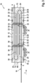
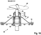
- a particularly preferred embodiment of the device is characterized in that at least two pump devices are arranged along each transport path and each pump device comprises a pump body with a vertically directed drive shaft with a rotating impeller and a drive, wherein at least the impeller is arranged in the area of the bottom wall of the or each brewing channel section within the brewing tank and the drive is arranged outside the brewing tank.
- a vertically directed drive shaft means that it is aligned essentially perpendicular to the bottom wall. The drive shaft extends from the bottom wall of the brewing tank upwards towards the bottom wall of the brewing channel. This ensures a high suction effect over the entire length of each transport path up to the deflection area.
- the placement of the drives outside the brewing tank ensures that they are effectively protected against the ingress of brewing medium.
- the number and positioning of the pump devices which are variable in each case, creates an embodiment that generates an overpressure below the entire brewing channel in the chamber that is sufficient to suck the brewing medium out of the brewing channel over its entire length and vertically upwards through the free spaces, at past the means for heating the brewing medium, so that the then (re)heated brewing medium flows back into the brewing channel from above on both sides.
- the preferred orientation of the drive shaft naturally also applies to designs with at least one pump device.
- At least one row, preferably two rows, of pump devices is/are formed and arranged transversely to the longitudinal extension of the linear brewing channel sections, wherein the maximum distance between the pump devices to the curved brewing channel sections is approximately 3.5 m.
- a row comprises at least two, in other embodiments also three or more pump devices, which are preferably arranged in a line transverse to the transport direction.
- the individual pump devices in a row can also be arranged offset from one another.
- the pump devices in a row form a pump module.
- the associated drives for the impellers of each pump device can be arranged on one side or on opposite sides of the pump module.
- a belt drive is used to transmit the drive torque to the vertically directed drive axes.
- other drive concepts can also be used.
- two or more pump devices in a row form a pump module, which together with middle modules with linear brewing channel sections and end modules with linear and curved brewing channel sections forms a modular device with the continuous brewing channel.
- the modular design of the device allows it to be easily adapted to different circumstances.
- the simple replacement of one or each pump module and/or the addition of pump modules is also advantageous, since the device can be adapted to different lengths and/or different performance levels, for example.
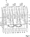
- a particularly advantageous embodiment is characterized in that adjacent partition walls delimiting a scalding channel section have different heights, such that a partition wall facing the back of the poultry is lower than an opposite partition wall facing the breast of the poultry.
- the different heights of the partition walls affect both the linear and the curved scalding channel sections, so that this effect can extend over the entire length of the scalding channel.
- the transport means and the scalding tank are arranged and set up in such a way that the poultry is transported sideways through the scalding channel, so that the back and breast sides face the two partition walls delimiting the scalding channel.
- the back and breast sides can optionally be supplied with different volumes, for example by means of a targeted pump control.
- the different construction heights of the two scalding channels are particularly simple and effective. delimiting partition walls, so that with a partition wall of lower height the scalding medium hits the back side sooner and with more volume than the breast side. This can be used to specifically ensure that the poultry has more feathers and feathers that are harder to remove on the back side than on the breast side, which is why a more intensive scalding process with a larger scalding volume is aimed for on the back side than on the breast side.
- the height of at least one of the partition walls of each scalding channel section is designed to be variably adjustable.
- a partition wall preferably the partition wall facing the back
- Other options are, for example, motor-adjustable solutions. Regardless of the technical implementation of the adjustability of one or both partition walls, this enables individual adjustment of the volumes flowing to the back or breast side, for example depending on the size of the poultry to be scalded, to improve the scalding result.
- a preferred contour provides that the width of the scalding channel is reduced at least in sections, such that the overflowing scalding medium is directed in the direction of the poultry, whereby the scalding medium is directed at the poultry with greater force and at a higher speed and hits it.
- This effect allows the scalding medium to penetrate more efficiently through the firmer cover feathers in the outer layers towards the skin in order to loosen the feathers at the transition to the skin, thereby improving the scalding result.
- the poultry absorbs scalding medium during transport along the scalding channel i.e. scalding water is partially absorbed by the poultry, particularly through its plumage
- compensation is optionally only carried out via the nozzle device in order to compensate for the water loss. This can also compensate for the water loss that occurs when the contaminated water is drained off in the input area.
- the pump devices arranged along the scalding channel serve primarily and preferably exclusively for the internal circulation of the scalding medium within the scalding tank and preferably have no influence on the amount of water in the scalding tank.
- the water circuit that circulates within the pressure chamber is thus virtually decoupled or isolated from the "True Counterflow".
- a pump device can be assigned exclusively to a transport path or a brewing channel section.
- an impeller of each pump device is advantageously arranged in an area of an opening in the bottom wall of the brewing channel section to establish a flow connection between the brewing channel section and the receiving space, wherein the impeller is at least partially shielded from the brewing channel section by a cover arranged and designed at a distance from the impeller.
- the cover can be a grid.
- the or each pump device supplies at least two transport paths or brewing channel sections.
- an impeller of each pump device is arranged in a region of an opening in a bottom wall and/or a partition wall of at least two brewing channel sections to produce a flow connection between at least two adjacent brewing channel sections and the receiving space. arranged, the impeller being completely shielded from the free space formed between adjacent partition walls of adjacent brewing channel sections.
- a preferred embodiment establishes the connection between the brewing channel section and the receiving space by means of partial openings in the respective base wall and partial openings in both partition walls delimiting the free space.
- At least one drain valve is assigned to the brewing tank.
- the or each drain valve is preferably located in the input area.
- the number and positioning of the drain valves can vary.
- fresh water is supplied from the output area towards the input area to generate a countercurrent against the transport direction T of the poultry, so that the poultry is transported against the flow of the fresh water and contaminated scalding medium collects in the input area and the poultry is transported towards the output area through increasingly clean scalding medium.
- the method is particularly preferably carried out with a device according to one or more of claims 1 to 17.
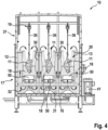
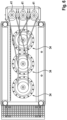
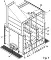
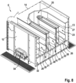
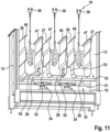
- the device shown in the drawing is used for scalding chickens that are hanging upside down and are transported within the scalding tank by a scalding medium, namely in such a way that the chickens are at least partially below the surface of the scalding medium, so that the chickens are exposed to the scalding medium in the transport sections and additionally to the scalding medium flowing out of the channel at the front sides and at the top.
- this device 10 is characterized in that the receiving space 31 extends below the entire brewing channel 20, i.e. between the bottom walls 28 of the linear and curved brewing channel sections on the one hand and the bottom wall 16 of the brewing tank 17 on the other hand, wherein in the receiving space 31 extending into the region of the curved brewing channel sections, at least one pump device 34 is arranged as a swirling body 33 for forming a pressure chamber 35 acting along the entire brewing channel 20.
- the brewing tank 17 is a tub-like body which is limited downwards by the bottom wall 16 and laterally/outside by the side walls 12, 13 and the front walls 14, 15.
- the brewing tank 17 extends longitudinally in the transport direction T of the transport means 19.
- the brewing medium 18 can be water or another fluid, for example water enriched with at least one additive or the like.
- the bottom wall 16 can be horizontal and flat, V-shaped or shaped in another way.
- the brewing tank 17 can be one-piece or modular or segment-like and in the variant shown has a total length of preferably approx. 8-10m. The dimensions of the brewing tank 17 can vary, however.
- the scalding tank 17 can optionally have a cover 37 which essentially encloses the transport means 19. In order to avoid collisions between the transport means 19 and the cover hood 37, an opening is provided in the cover hood 37 in the input area E and in the output area A, through which the conveyor rail can enter and exit the brewing tank 17.
- the means 30 for supplying and/or heating scalding medium 18 can optionally be used to supply steam or hot water into the scalding tank 17.
- the means 30 is primarily designed to heat scalding medium 18, which flows vertically upwards in the free spaces 29 in the direction of the free edges of the partition walls 26, 27.
- the means 30 can be a simple heat exchanger. However, other heating means or heating elements can also be used. Because the means 30 are arranged in the free spaces 29 shielded from the transport routes 21 to 23 of the scalding channel 20, the poultry 11 is protected from direct heat radiation.
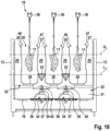
- each linear brewing channel section is assigned at least one separate pump device 34.
- each transport path 21 to 23 has at least one pump device 34.
- Two pump devices 34 are assigned to each of the three transport routes 21 to 23.
- Each pump device 34 only acts on one transport route 21 to 23. This means that the suction and pumping effect of each pump device 34 is essentially limited to a single transport route 21 to 23.
- the impeller 40 is located centrally below the bottom wall 28 of the brewing channel 20.
- the number of pump devices 34 can basically vary and can also be different between the individual transport routes 21 to 23.
- the Pump devices 34 of adjacent transport routes 21 to 23 are arranged next to one another transversely to the transport direction T.
- At least one common pump device 34 is assigned to at least two adjacent and parallel brewing channel sections.
- Each pump device 34 acts on two transport routes 21, 22 or 22, 23. This means that a pump device 34 sucks brewing medium 18 from two transport routes 21, 22 or 22, 23 and pumps it back via free spaces 29 into two adjacent transport routes 21, 22 or 22, 23 of the brewing channel 20, in that the impeller 40 is arranged centrally between two transport routes 21, 22 or 22, 23, i.e. essentially centrally below a free space 29 separating the two transport routes 21, 22 or 22, 23 from one another. It is also possible for a pump device 34 to be assigned to three or more transport routes 21 to 23.
- At least one row, preferably two rows, of pump devices 34 is/are formed and arranged transversely to the longitudinal extension of the linear brewing channel sections, the maximum distance between the pump devices 34 and the curved brewing channel sections being approximately 3.5 m.
- a row formation of the pump devices 34 to form a pump module 42 is preferred.
- the drives 41 of the pump devices 34 can be arranged on one side or both sides of the pump module 42.
- Such a pump module 42 forms, together with middle modules 43 with linear brewing channel sections and end modules 44 with linear brewing channel sections and curved brewing channel sections, a modular device 10 with the continuous brewing channel 20.
- Such a device 10 formed from the modules 42, 43, 44 can be used as a single brewing device.
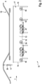
- two or more such single brewing devices can also be connected to one another to form a brewing line 45 (see e.g. Figure 17 ).
- the number of modules 42 to 44 can be variable and individually adapted.
- the maximum distance between the pump devices 34 should not only be 3.5m to the curved brewing channel sections, i.e. to the curved connecting sections 24, 25, in the deflection area, but also between the individual pump devices 34 in the transport direction T, in order to ensure a uniform flow over the entire Length of the brewing channel 20 to provide sufficient suction and pumping power in all areas of the brewing tank 17.
- the distance can of course be reduced.
- a larger distance between the pump devices 34 and/or the curved connecting sections 24, 25 is also possible in principle.
- the guide elements 46, 47 can also be shaped and/or directed differently, for example such that the overflowing scalding medium 18 is directed essentially in the transport direction T into the scalding channel, in particular at a particularly high transport speed of the poultry 11, in order to additionally press the poultry 11 in the transport direction T through the scalding medium 18 located in the scalding channel 20.
- the partition walls 26, 27 can have the same height starting from the bottom wall 28 that connects the partition walls 26, 27.
- adjacent partition walls 26, 27 delimiting a scalding channel section have different heights, such that a partition wall 27 facing the back side of the poultry 11 is lower than an opposite partition wall 26 facing the breast side of the poultry 11.
- the different heights of the partition walls 26, 27 can be continuous along the entire scalding channel 20, i.e. along the linear transport sections 21 to 23 and the curved connecting sections 24, 25.
- the height difference can optionally also be formed only in sections.
- the partition wall 27 facing the back side can be at least one centimeter, optionally also at least two centimeters and further optionally also at least three centimeters lower than the partition wall 26 facing the breast side. Of course, the difference can also be greater than three centimeters and less than one centimeter.
- both partition walls 26, 27 are preferably designed such that the scalding channel 20 is partially narrowed.
- the partition walls 26, 27 are uneven and, starting from the free edges and initially running perpendicular to the base wall 28, have an inward-directed path which initially guides the brewing medium 18 inwards towards the poultry 11 to be brewed, then is aligned perpendicular to the base wall 28 at the height of the poultry 11 to be brewed in order to narrow the brewing channel 20, and then runs outwards again to the original width of the brewing channel 20, before finally ending perpendicular to the base wall 28.
- Other shapes and contours of the partition walls 26, 27 can also be used.
- a shape which is actually adapted to the external geometry of the poultry 11 to be brewed can also be implemented in one partition wall 26 or 27 or in both partition walls 26, 27.
- the scalding tank 17 can basically be filled with scalding medium 18 in any way.
- filling is ensured by means of the means 30.
- at least one nozzle device for introducing preferably heated, clean water is arranged, while in the input area E of the poultry 11 into the scalding tank 17, at least one outlet (not explicitly shown) for draining the dirty water is formed.
- the position of the nozzle device and/or the or each outlet can vary and is not limited to end walls 14, 15 of the scalding tank 17.
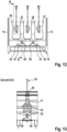
- an impeller 40 of each pump device 34 is arranged in a region of an opening 49 in the bottom wall 28 of the brewing channel section to produce a flow connection between a brewing channel section and the receiving space 31, wherein the impeller 40 is at least partially shielded from the brewing channel section by a hood or cover 50 arranged and formed at a distance from the impeller 40 (see in particular Figures 4 and 5 ).
- the cover 50 can have various designs and comprises at least one opening 51.
- the brewing medium 18 located in the brewing channel 20 and the brewing medium 18 flowing over the partition walls 26, 27 on both sides are sucked out of the brewing channel 20 into the receiving space 31 in the area of the base wall 28 via the or each opening 51 and the opening 49 and are returned from above into the brewing channel 20 via the free spaces 29, so that circulation of the brewing medium is ensured.
- the previously described counterflow of fresh water from the output area A towards the input area E can be used in addition to this circulation.
- the brewing medium 18 located in the brewing channel 20 and the brewing medium 18 flowing over the partition walls 26, 27 on both sides are sucked out of the brewing channel 20 into the receiving space 31 in the area of the base wall 28 and over the partition wall 26 or 27 via the opening 52 and fed back into the brewing channel 20 from above via the free spaces 29, so that a circulation of the brewing medium is ensured.
- the previously described counterflow of fresh water from the output area A towards the input area E can be used in addition to this circulation.
- At least one turbulence body (not explicitly shown) is arranged along the scalding channel 20 as a means for generating turbulence and/or flow of the scalding medium 18, which can be driven in rotation by means of a drive shaft directed horizontally and transversely to the transport direction T of the poultry 11.
- a so-called vortex water turbine is arranged in particular in the area of the curved connecting sections 24, 25, but can ultimately be positioned at any position along the scalding channel 20.
- the device 10 is associated with a control device 55 at least for controlling and/or regulating the means 30 for heating the brewing medium 18.
- a control device 55 at least for controlling and/or regulating the means 30 for heating the brewing medium 18.
- other components such as the or each drain valve 48, the nozzle unit, the drives 41 of the pump devices 34, potential servomotors, e.g. for changing the height of the or each partition wall 26, 27, and other components can also be connected to the control device.
- the suction effect also leads to the poultry 11 being "pulled” from the floating, swollen position into a position essentially hanging downwards and thus being stabilized.
- the brewing medium 18 flowing over from above then hits evenly aligned poultry 11 or supports the alignment of the poultry 11 for an efficient brewing process.
- the scalding medium 18 is swirled within the scalding tank 20 by means of at least one swirling body 33, whereby the scalding medium 18 is guided from a receiving space 31 below the scalding channel 20 in sections from above back into the scalding channel 20.
- the scalding process is carried out by transporting the poultry 11 along the scalding channel 20.
- a preferred setting of the pump device 34 with regard to the drive speed of the impellers 40 when the filling level of the brewing tank 17 with brewing medium 18 is between the "low level” L L and a filling level between "low level” L L and "high level” H L is approximately 900 rpm.
- a drive speed of the impellers of approximately 540 rpm is preferred (see in particular Figure 10 ). Of course, other drive speeds can also be implemented.
Landscapes
- Engineering & Computer Science (AREA)
- Life Sciences & Earth Sciences (AREA)
- Food Science & Technology (AREA)
- Wood Science & Technology (AREA)
- Zoology (AREA)
- Mechanical Engineering (AREA)
- Processing Of Meat And Fish (AREA)
- Housing For Livestock And Birds (AREA)
- Devices For Post-Treatments, Processing, Supply, Discharge, And Other Processes (AREA)
Claims (25)
- Dispositif (10), configuré et adapté pour l'échaudage de volailles abattues (11), comprenant un réservoir d'échaudage (17) allongé, fermé latéralement sur tout le pourtour par des parois latérales (12, 13) et des parois frontales (14, 15) et vers le bas par une paroi de fond (16) et ouvert vers le haut, destiné à recevoir et à contenir un milieu d'échaudage liquide (18), un moyen de transport (19) agencé au-dessus du réservoir d'échaudage (17) pour le transport suspendu de la volaille (11) à l'intérieur du réservoir d'échaudage (17) le long d'un canal d'échaudage (20) formé de plusieurs sections de canal d'échaudage, depuis une zone d'entrée (E) vers une zone de sortie (A), au moins deux trajets de transport (21, 22, 23) pour la volaille (11) à l'intérieur du réservoir d'échaudage (17) étant configurés respectivement d'un côté frontal du réservoir d'échaudage (17) au côté frontal opposé du réservoir d'échaudage (17) et les trajets de transport (21, 22, 23) étant reliés entre eux au moyen de trajets de liaison courbes (24, 25) pour une déviation de 180 degrés, chaque trajet de transport (21 à 23) et chaque trajet de liaison (24, 25) étant délimités par deux parois de séparation (26, 27) agencées à distance l'une de l'autre transversalement à la direction de transport T et par une paroi de fond (28) pour former des sections de canal d'échaudage linéaires ouvertes vers le haut et des sections de canal d'échaudage courbes ouvertes vers le haut, des parois de séparation (26, 27) de sections de canal d'échaudage voisines ainsi que des parois de séparation (26, 27) qui sont voisines de parois extérieures du réservoir d'échaudage (17) étant agencées à distance les unes des autres pour former un espace libre (29) pour le milieu d'échaudage (18), des moyens (30) pour amener et/ou chauffer le milieu d'échaudage (18) étant associés au moins aux espaces libres (29) de sections de canal d'échaudage voisines, et un espace de réception (31) pour le milieu d'échaudage (18) étant formé en dessous d'au moins des parties du canal d'échaudage (20), à savoir au moins entre les parois de fond (28) des sections de canal d'échaudage linéaires et la paroi de fond (16) du réservoir d'échaudage (17), lequel forme conjointement avec les espaces libres (29) une chambre commune (32), à laquelle est associé au moins un corps de tourbillonnement (33) pour produire un tourbillonnement et/ou un écoulement du milieu d'échaudage (18) dans le réservoir d'échaudage (20), caractérisé en ce que l'espace de réception (31) s'étend en dessous de l'ensemble du canal d'échaudage (20), donc entre les parois de fond (28) des sections de canal d'échaudage linéaires et courbes d'une part et la paroi de fond (16) du réservoir d'échaudage (17) d'autre part, au moins un appareil de pompage (34) étant agencé dans l'espace de réception (31) s'étendant ainsi jusque dans la zone des sections de canal d'échaudage courbes, en tant que corps de tourbillonnement (33) pour former une chambre de pression (35) agissant le long de l'ensemble du canal d'échaudage (20).
- Dispositif (10) selon la revendication 1, caractérisé en ce que le long de chaque trajet de transport (21 à 23) sont agencés au moins deux appareils de pompage (34) et chaque appareil de pompage (34) comprend un corps de pompe (38) avec un arbre d'entraînement (39) dirigé verticalement avec une roue à pales (40) pouvant être entraînée en rotation ainsi qu'un entraînement (41), au moins la roue à pales (40) étant agencée dans la zone de la paroi de fond (28) de la ou de chaque section de canal d'échaudage à l'intérieur du réservoir d'échaudage (17) et l'entraînement (41) étant agencé à l'extérieur du réservoir d'échaudage (17).
- Dispositif (10) selon la revendication 1 ou 2, caractérisé en ce qu'au moins un appareil de pompage (34) séparé est associé à chaque section de canal d'échaudage linéaire.
- Dispositif (10) selon une ou plusieurs des revendications 1 à 3, caractérisé en ce qu'au moins un appareil de pompage (34) commun est associé à au moins deux sections de canal d'échaudage voisines et parallèles entre elles.
- Dispositif (10) selon une ou plusieurs des revendications 1 à 4, caractérisé en ce qu'au moins une rangée, de préférence deux rangées, d'appareils de pompage (34) est/sont configurée(s) et agencée(s) transversalement à l'extension longitudinale des sections de canal d'échaudage linéaires, la distance maximale entre les appareils de pompage (34) et les sections de canal d'échaudage courbes étant d'environ 3,5 m.
- Dispositif (10) selon la revendication 5, caractérisé en ce que deux ou plus de deux appareils de pompage (34) d'une rangée forment un module de pompage (42) qui, conjointement avec des modules centraux (43) avec des parties de section de canal d'échaudage linéaires et des modules d'extrémité (44) avec des parties de section de canal d'échaudage linéaires et des sections de canal d'échaudage courbes, forme un dispositif modulaire (10) avec le canal d'échaudage continu (20).
- Dispositif (10) selon une ou plusieurs des revendications 1 à 6, caractérisé en ce que des parois de séparation (26, 27) voisines délimitant une section de canal d'échaudage présentent des hauteurs différentes, de telle sorte qu'une paroi de séparation (27) tournée vers le côté dos de la volaille (11) est configurée plus basse qu'une paroi de séparation (26) opposée tournée vers le côté poitrine de la volaille (11).
- Dispositif (10) selon la revendication 7, caractérisé en ce que la paroi de séparation (27) tournée vers le côté dos est plus basse d'au moins un centimètre, éventuellement même d'au moins deux centimètres et éventuellement encore d'au moins trois centimètres, que la paroi de séparation (26) tournée vers le côté poitrine.
- Dispositif (10) selon une ou plusieurs des revendications 1 à 8, caractérisé en ce que la hauteur d'au moins une des parois de séparation (26, 27) de chaque section de canal d'échaudage est configurée pour être réglable de manière variable.
- Dispositif (10) selon une ou plusieurs des revendications 1 à 9, caractérisé en ce qu'au moins l'une des parois de séparation (26, 27) d'une section de canal d'échaudage présente, au moins sur un côté intérieur tourné vers le trajet de transport (21 à 23), une forme adaptée au moins par sections au contour de la volaille (11).
- Dispositif (10) selon une ou plusieurs des revendications 1 à 10, caractérisé en ce que, pour former un contre-courant dirigé à l'encontre de la direction de transport de la volaille (11), au moins un appareil de buse est agencé dans la zone de sortie (A) de la volaille du réservoir d'échaudage (17) pour introduire de l'eau propre, de préférence chauffée, tandis que dans la zone d'entrée (E) de la volaille (11) dans le réservoir d'échaudage (17) est configurée au moins une sortie pour évacuer l'eau sale.
- Dispositif (10) selon une ou plusieurs des revendications 3 et 5 à 11, caractérisé en ce qu'une roue à pales (40) de chaque appareil de pompage (34) est agencée dans une zone d'une percée (49) de la paroi de fond (28) de la section de canal d'échaudage pour établir une liaison d'écoulement entre une section de canal d'échaudage et l'espace de réception (31), la roue à pales (40) étant au moins partiellement protégée par rapport à la section de canal d'échaudage par un couvercle (50) agencé et configuré à distance de la roue à pales (40).
- Dispositif (10) selon une ou plusieurs des revendications 4 à 11, caractérisé en ce qu'une roue à pales (40) de chaque appareil de pompage (34) est agencée dans une zone d'une percée (52) respectivement d'une paroi de fond (28) et/ou d'une paroi de séparation (26, 27) d'au moins deux sections de canal d'échaudage pour établir une liaison d'écoulement entre au moins deux sections de canal d'échaudage voisines et l'espace de réception (31), la roue à pales (40) étant entièrement protégée par rapport à l'espace libre (29) formé entre des parois de séparation voisines (26, 27) de sections de canal d'échaudage voisines.
- Dispositif (10) selon une ou plusieurs des revendications 1 à 13, caractérisé en ce que le long du canal d'échaudage (20) est agencé au moins un corps de tourbillonnement en tant que moyen de production de tourbillonnement et/ou d'écoulement du milieu d'échaudage (18), qui peut être entraîné en rotation au moyen d'un arbre d'entraînement dirigé horizontalement et dirigé transversalement à la direction de transport T de la volaille (11).
- Dispositif (10) selon une ou plusieurs des revendications 1 à 14, caractérisé en ce que dans la zone des parois latérales (12, 13) du réservoir d'échaudage (17) est configurée au moins une ouverture (54) pouvant être fermée pour accéder à la chambre de pression (35), de préférence dans la zone d'entrée (E).
- Dispositif (10) selon une ou plusieurs des revendications 1 à 15, caractérisé en ce qu'au moins une soupape d'évacuation (48) est associée au réservoir d'échaudage (17).
- Dispositif (10) selon une ou plusieurs des revendications 1 à 16, caractérisé en ce que le dispositif (10) est associé à un appareil de commande au moins pour commander et/ou réguler les moyens (30) de chauffage du milieu d'échaudage (18).
- Procédé d'échaudage de volailles abattues (11), comprenant les étapes suivantes :- le transport de la volaille (11) suspendue par les pattes à travers un réservoir d'échaudage (17) au moins partiellement rempli de milieu d'échaudage liquide (18) au moyen d'un moyen de transport (19) dans la direction de transport T depuis une zone d'entrée (E) vers une zone de sortie (A) le long d'un canal d'échaudage (20), le canal d'échaudage (20) comprenant des sections de canal d'échaudage linéaires et courbes,- le chauffage et/ou l'amenée du milieu d'échaudage (18) par des moyens (30) pour chauffer et/ou amener le milieu d'échaudage (18), et- le tourbillonnement du milieu d'échaudage (18) à l'intérieur du réservoir d'échaudage (17) au moyen d'au moins un corps de tourbillonnement (33), moyennant quoi le milieu d'échaudage (18) est ramené par sections par le haut dans le canal d'échaudage (20) à partir d'un espace de réception (31) en dessous du canal d'échaudage (20),caractérisé en ce que le milieu d'échaudage (18) est aspiré par le bas hors du canal d'échaudage (20) au moyen d'au moins un appareil de pompage (34) et est pompé sur toute la longueur du canal d'échaudage (20), c'est-à-dire dans la zone des sections de canal d'échaudage linéaires et courbes, des deux côtés de celui-ci, en retour par le haut dans le canal d'échaudage (20).
- Procédé selon la revendication 18, caractérisé en ce que la volaille (11) est transportée latéralement à travers le canal d'échaudage (20) délimité par des parois de séparation (26, 27) opposées l'une à l'autre, de telle sorte que la volaille (11) est dirigée lors du transport avec un côté dos vers une paroi de séparation (27) et avec un côté poitrine vers la paroi de séparation (26) opposée, un volume de milieu d'échaudage plus important étant renvoyé par le haut dans le canal d'échaudage (20) par l'intermédiaire de la paroi de séparation (27) qui est tournée vers le côté dos que par l'intermédiaire de la paroi de séparation (26) qui est tournée vers le côté poitrine.
- Procédé selon la revendication 18 ou 19, caractérisé en ce que de l'eau fraîche est amenée à partir de la zone de sortie (A) en direction de la zone d'entrée (E) pour produire un contre-courant à l'encontre de la direction de transport T de la volaille (11), de telle sorte que la volaille (11) est transportée à l'encontre du courant d'eau fraîche et le milieu d'échaudage sale (18) s'accumule dans la zone d'entrée (E) et la volaille (11) est transportée en direction de la zone de sortie (A) par un milieu d'échaudage de plus en plus propre (18).
- Procédé selon une ou plusieurs des revendications 18 à 20, caractérisé en ce que la volaille (11) est au choix totalement, partiellement ou pas du tout immergée dans le milieu d'échaudage (18) lors du transport à travers le canal d'échaudage (20).
- Procédé selon une ou plusieurs des revendications 18 à 21, caractérisé en ce que le milieu d'échaudage (18) est nettoyé au moyen d'un appareil de filtration.
- Procédé selon une ou plusieurs des revendications 18 à 22, caractérisé en ce que le milieu d'échaudage (18) circule lui-même à l'intérieur du réservoir d'échaudage (17), à savoir qu'il est aspiré hors du canal d'échaudage (20) et renvoyé dans le canal d'échaudage (20) sous forme de trop-plein des deux côtés, et de l'eau fraîche préchauffée est pompée dans le canal d'échaudage (20) dans la zone de sortie (A) à l'encontre de la direction de transport T, avec une pression.
- Procédé selon une ou plusieurs des revendications 18 à 23, caractérisé en ce que le milieu d'échaudage (18) est aspiré hors du canal d'échaudage (20) dans la zone de parois de fond (28) avec plusieurs appareils de pompage (34) et est pompé vers le haut des deux côtés du canal d'échaudage (20), de telle sorte qu'il s'écoule en retour des deux côtés par le haut dans le canal d'échaudage (20), au moins un appareil de pompage (34) alimentant à chaque fois au choix une section de canal d'échaudage ou au moins deux sections de canal d'échaudage.
- Procédé selon une ou plusieurs des revendications 18 à 24, caractérisé en ce qu'il est mis en oeuvre avec un dispositif (10) selon une ou plusieurs des revendications 1 à 17.
Priority Applications (1)
| Application Number | Priority Date | Filing Date | Title |
|---|---|---|---|
| PL20712459.5T PL4051007T3 (pl) | 2020-03-06 | 2020-03-06 | Urządzenie i sposób sparzania ubitego drobiu |
Applications Claiming Priority (1)
| Application Number | Priority Date | Filing Date | Title |
|---|---|---|---|
| PCT/EP2020/056022 WO2021175438A1 (fr) | 2020-03-06 | 2020-03-06 | Dispositif et procédé d'échaudage de volailles abattues |
Publications (2)
| Publication Number | Publication Date |
|---|---|
| EP4051007A1 EP4051007A1 (fr) | 2022-09-07 |
| EP4051007B1 true EP4051007B1 (fr) | 2025-01-22 |
Family
ID=69846405
Family Applications (1)
| Application Number | Title | Priority Date | Filing Date |
|---|---|---|---|
| EP20712459.5A Active EP4051007B1 (fr) | 2020-03-06 | 2020-03-06 | Dispositif et procédé d'échaudage de volailles abattues |
Country Status (10)
| Country | Link |
|---|---|
| US (1) | US11638430B2 (fr) |
| EP (1) | EP4051007B1 (fr) |
| JP (1) | JP7289407B2 (fr) |
| KR (1) | KR102603132B1 (fr) |
| CN (1) | CN114929023B (fr) |
| CA (1) | CA3156957C (fr) |
| DK (1) | DK4051007T3 (fr) |
| ES (1) | ES3013575T3 (fr) |
| PL (1) | PL4051007T3 (fr) |
| WO (1) | WO2021175438A1 (fr) |
Families Citing this family (2)
| Publication number | Priority date | Publication date | Assignee | Title |
|---|---|---|---|---|
| AU2022328751B2 (en) * | 2021-08-17 | 2025-06-26 | Safe Foods Corporation | Dual waterfall cabinet for food processing applications |
| CN118949555B (zh) * | 2024-10-17 | 2025-01-07 | 中红三融集团有限公司 | 一种自动化的肉鸡屠宰设备 |
Family Cites Families (22)
| Publication number | Priority date | Publication date | Assignee | Title |
|---|---|---|---|---|
| US2668661A (en) | 1944-11-23 | 1954-02-09 | Bell Telephone Labor Inc | Complex computer |
| US2667661A (en) | 1950-08-01 | 1954-02-02 | Swift & Co | Method of scalding poultry |
| US2727273A (en) * | 1950-08-01 | 1955-12-20 | Swift & Co | Poultry scald tank |
| US2649615A (en) * | 1950-08-05 | 1953-08-25 | Barker Poultry Equipment Compa | Sectional scalding tank for fowl |
| US3343477A (en) * | 1964-09-30 | 1967-09-26 | Ekstam Martin Rudolf | Arrangement in apparatus for hot water treatment of goods |
| JPS4841996B1 (fr) * | 1969-05-24 | 1973-12-10 | ||
| JPS5555587Y2 (fr) * | 1977-03-18 | 1980-12-23 | ||
| KR840000937Y1 (ko) * | 1982-10-05 | 1984-06-14 | 범진기건주식회사 | 닭의 데침기 |
| JPS6072186U (ja) * | 1983-10-21 | 1985-05-21 | アイスマン製氷機工業株式会社 | ブロイラ−等の湯漬機 |
| JPS60191192U (ja) * | 1984-05-30 | 1985-12-18 | 株式会社石井製作所 | ブロイラ−用湯漬け装置 |
| US4947518A (en) | 1989-10-11 | 1990-08-14 | Covell Iii Edward H | Poultry scalding system and process |
| US4961248A (en) * | 1990-01-19 | 1990-10-09 | Johnson Food Equipment, Inc. | Scalder apparatus |
| US5190494A (en) * | 1992-01-21 | 1993-03-02 | Edward H. Covell, III | Poultry scalder |
| US5232394A (en) * | 1992-01-21 | 1993-08-03 | Covell Iii Edward H | Poultry scalder |
| US7189157B2 (en) * | 2003-11-05 | 2007-03-13 | Linco Food Systems A/S | Method and a device for the preparation of slaughtered poultry for picking |
| US8066556B2 (en) * | 2004-09-03 | 2011-11-29 | Linco Food Systems A/S | Method and system for scalding slaughtered poultry |
| NL2000158C2 (nl) | 2006-07-24 | 2008-01-25 | Stork Pmt | Inrichting en werkwijze voor het broeien van pluimvee. |
| NL2002250C2 (nl) | 2008-11-25 | 2010-05-26 | Stork Pmt | Inrichting en werkwijze voor het met uiteenlopende intensiteiten broeien van verschillende onderdelen van een pluimveekarkas. |
| KR20120107149A (ko) * | 2011-03-17 | 2012-09-28 | 주식회사 매산씨앤에프 | 냉장용 육계의 탕적장치 |
| KR20120107154A (ko) * | 2011-03-17 | 2012-10-02 | 주식회사 매산씨앤에프 | 냉장용 육계의 가공방법 |
| DE102015104652B3 (de) | 2015-03-26 | 2016-02-25 | Linco Food Systems A/S | Vorrichtung und Verfahren zum Brühen von geschlachtetem Geflügel |
| CN209420791U (zh) * | 2018-12-09 | 2019-09-24 | 怀化市明友食品有限责任公司 | 一种家禽脱毛机 |
-
2020
- 2020-03-06 PL PL20712459.5T patent/PL4051007T3/pl unknown
- 2020-03-06 WO PCT/EP2020/056022 patent/WO2021175438A1/fr not_active Ceased
- 2020-03-06 JP JP2022538982A patent/JP7289407B2/ja active Active
- 2020-03-06 US US17/779,099 patent/US11638430B2/en active Active
- 2020-03-06 KR KR1020227019118A patent/KR102603132B1/ko active Active
- 2020-03-06 CA CA3156957A patent/CA3156957C/fr active Active
- 2020-03-06 CN CN202080080736.8A patent/CN114929023B/zh active Active
- 2020-03-06 ES ES20712459T patent/ES3013575T3/es active Active
- 2020-03-06 EP EP20712459.5A patent/EP4051007B1/fr active Active
- 2020-03-06 DK DK20712459.5T patent/DK4051007T3/da active
Also Published As
| Publication number | Publication date |
|---|---|
| CA3156957C (fr) | 2023-01-10 |
| CN114929023B (zh) | 2023-04-28 |
| PL4051007T3 (pl) | 2025-05-26 |
| US20220408742A1 (en) | 2022-12-29 |
| WO2021175438A1 (fr) | 2021-09-10 |
| KR102603132B1 (ko) | 2023-11-15 |
| JP2023500986A (ja) | 2023-01-17 |
| JP7289407B2 (ja) | 2023-06-09 |
| BR112022008972A2 (pt) | 2022-08-02 |
| CN114929023A (zh) | 2022-08-19 |
| CA3156957A1 (fr) | 2021-09-10 |
| US11638430B2 (en) | 2023-05-02 |
| KR20220119016A (ko) | 2022-08-26 |
| ES3013575T3 (en) | 2025-04-14 |
| DK4051007T3 (da) | 2025-03-24 |
| EP4051007A1 (fr) | 2022-09-07 |
Similar Documents
| Publication | Publication Date | Title |
|---|---|---|
| DE2130967C3 (de) | Vorrichtung zum Trennen zweier in einer heterogenen Flüssigkeit enthaltender Flüssigkeitsbestandteile | |
| EP4051007B1 (fr) | Dispositif et procédé d'échaudage de volailles abattues | |
| EP3273785B1 (fr) | Appareil et procédé d'échaudage de volailles abattues | |
| DE602004000708T2 (de) | Tunnelspritzgerät für Reihen von Obstgärten, Weingärten oder andere Pflanzen | |
| DE2002056C3 (de) | Zerstäubungskühler, insbesondere Kühlturm zur Abkühlung von Wasser | |
| DE4014955C1 (fr) | ||
| DE3328589C2 (fr) | ||
| DE102018213722A1 (de) | Ein behälter, ein verbrennungsmotor, ein fahrzeug und ein verfahren | |
| DE3876808T2 (de) | Anordnung zum erzeugen eines homogenen flusses eines kuehlmittels. | |
| EP3162717B1 (fr) | Machine de verrouillage de coques dotee d'un dispositif d'equilibrage des temperatures | |
| DE1964208A1 (de) | Verfahren und Vorrichtung zur Rueckgewinnung eines Stoffes,der Form einer duennen Schicht auf der Oberflaeche einer fluessigen Mas schwimmt | |
| DE3903319C1 (fr) | ||
| DE1900807A1 (de) | Verfahren und Vorrichtung zum Handhaben von Fluessigkeiten | |
| DE1767198A1 (de) | Vorrichtung zum Erhitzen und Anfeuchten von bahnfoermigem Material | |
| DE3024710C2 (de) | Trockner für rieselfähige Güter | |
| AT378469B (de) | Backofen | |
| DE2510576B2 (de) | Verfahren zur Reinigung von Schmutzgas und Reinigungsvorrichtung zur Durchführung des Verfahrens | |
| DE102021107094A1 (de) | Aufsitzbares Fahrzeug mit Flüssigkeitskühlvorrichtung | |
| DE1660415B2 (de) | Vorrichtung zur Wärmebehandlung einer Vielzahl von synthetischen Garnen | |
| DE814134C (de) | Verfahren und Einrichtung zur kontinuierlichen Hefezuechtung und Alkoholgewinnung | |
| DE2852416A1 (de) | Fluessigkeitssystem mit zusatztank und mehreren ausgleichsleitungen | |
| DE69001585T2 (de) | Einrichtung zur Wärmebehandlung eines erstarrbaren flüssigen Produktes und damit versehene Süsswareneinrichtung, wie eine Überzugs- und Abgussmaschine. | |
| BR112022008972B1 (pt) | Dispositivo e método para escaldar aves abatidas | |
| JPWO2021175438A5 (fr) | ||
| DE2637033A1 (de) | Mit einem dampf-luftgemisch betreibbarer ueberdruck-autoklav |
Legal Events
| Date | Code | Title | Description |
|---|---|---|---|
| STAA | Information on the status of an ep patent application or granted ep patent |
Free format text: STATUS: UNKNOWN |
|
| STAA | Information on the status of an ep patent application or granted ep patent |
Free format text: STATUS: THE INTERNATIONAL PUBLICATION HAS BEEN MADE |
|
| PUAI | Public reference made under article 153(3) epc to a published international application that has entered the european phase |
Free format text: ORIGINAL CODE: 0009012 |
|
| STAA | Information on the status of an ep patent application or granted ep patent |
Free format text: STATUS: REQUEST FOR EXAMINATION WAS MADE |
|
| 17P | Request for examination filed |
Effective date: 20220530 |
|
| AK | Designated contracting states |
Kind code of ref document: A1 Designated state(s): AL AT BE BG CH CY CZ DE DK EE ES FI FR GB GR HR HU IE IS IT LI LT LU LV MC MK MT NL NO PL PT RO RS SE SI SK SM TR |
|
| DAV | Request for validation of the european patent (deleted) | ||
| DAX | Request for extension of the european patent (deleted) | ||
| GRAP | Despatch of communication of intention to grant a patent |
Free format text: ORIGINAL CODE: EPIDOSNIGR1 |
|
| STAA | Information on the status of an ep patent application or granted ep patent |
Free format text: STATUS: GRANT OF PATENT IS INTENDED |
|
| INTG | Intention to grant announced |
Effective date: 20240905 |
|
| GRAS | Grant fee paid |
Free format text: ORIGINAL CODE: EPIDOSNIGR3 |
|
| GRAA | (expected) grant |
Free format text: ORIGINAL CODE: 0009210 |
|
| STAA | Information on the status of an ep patent application or granted ep patent |
Free format text: STATUS: THE PATENT HAS BEEN GRANTED |
|
| AK | Designated contracting states |
Kind code of ref document: B1 Designated state(s): AL AT BE BG CH CY CZ DE DK EE ES FI FR GB GR HR HU IE IS IT LI LT LU LV MC MK MT NL NO PL PT RO RS SE SI SK SM TR |
|
| P01 | Opt-out of the competence of the unified patent court (upc) registered |
Free format text: CASE NUMBER: APP_66767/2024 Effective date: 20241217 |
|
| REG | Reference to a national code |
Ref country code: GB Ref legal event code: FG4D Free format text: NOT ENGLISH |
|
| REG | Reference to a national code |
Ref country code: CH Ref legal event code: EP |
|
| REG | Reference to a national code |
Ref country code: IE Ref legal event code: FG4D Free format text: LANGUAGE OF EP DOCUMENT: GERMAN |
|
| REG | Reference to a national code |
Ref country code: DE Ref legal event code: R096 Ref document number: 502020010260 Country of ref document: DE |
|
| REG | Reference to a national code |
Ref country code: DK Ref legal event code: T3 Effective date: 20250321 |
|
| PGFP | Annual fee paid to national office [announced via postgrant information from national office to epo] |
Ref country code: SE Payment date: 20250311 Year of fee payment: 6 |
|
| PGFP | Annual fee paid to national office [announced via postgrant information from national office to epo] |
Ref country code: DE Payment date: 20250319 Year of fee payment: 6 |
|
| REG | Reference to a national code |
Ref country code: ES Ref legal event code: FG2A Ref document number: 3013575 Country of ref document: ES Kind code of ref document: T3 Effective date: 20250414 |
|
| PGFP | Annual fee paid to national office [announced via postgrant information from national office to epo] |
Ref country code: NL Payment date: 20250324 Year of fee payment: 6 |
|
| REG | Reference to a national code |
Ref country code: NL Ref legal event code: FP |
|
| PGFP | Annual fee paid to national office [announced via postgrant information from national office to epo] |
Ref country code: IE Payment date: 20250321 Year of fee payment: 6 |
|
| PGFP | Annual fee paid to national office [announced via postgrant information from national office to epo] |
Ref country code: AT Payment date: 20250409 Year of fee payment: 6 |
|
| PGFP | Annual fee paid to national office [announced via postgrant information from national office to epo] |
Ref country code: FR Payment date: 20250324 Year of fee payment: 6 |
|
| PGFP | Annual fee paid to national office [announced via postgrant information from national office to epo] |
Ref country code: GB Payment date: 20250324 Year of fee payment: 6 |
|
| REG | Reference to a national code |
Ref country code: SE Ref legal event code: TRGR |
|
| PG25 | Lapsed in a contracting state [announced via postgrant information from national office to epo] |
Ref country code: RS Free format text: LAPSE BECAUSE OF FAILURE TO SUBMIT A TRANSLATION OF THE DESCRIPTION OR TO PAY THE FEE WITHIN THE PRESCRIBED TIME-LIMIT Effective date: 20250422 |
|
| PG25 | Lapsed in a contracting state [announced via postgrant information from national office to epo] |
Ref country code: FI Free format text: LAPSE BECAUSE OF FAILURE TO SUBMIT A TRANSLATION OF THE DESCRIPTION OR TO PAY THE FEE WITHIN THE PRESCRIBED TIME-LIMIT Effective date: 20250122 |
|
| PGFP | Annual fee paid to national office [announced via postgrant information from national office to epo] |
Ref country code: PL Payment date: 20250303 Year of fee payment: 6 |
|
| PGFP | Annual fee paid to national office [announced via postgrant information from national office to epo] |
Ref country code: ES Payment date: 20250416 Year of fee payment: 6 Ref country code: DK Payment date: 20250407 Year of fee payment: 6 |
|
| REG | Reference to a national code |
Ref country code: LT Ref legal event code: MG9D |
|
| PG25 | Lapsed in a contracting state [announced via postgrant information from national office to epo] |
Ref country code: NO Free format text: LAPSE BECAUSE OF FAILURE TO SUBMIT A TRANSLATION OF THE DESCRIPTION OR TO PAY THE FEE WITHIN THE PRESCRIBED TIME-LIMIT Effective date: 20250422 Ref country code: IS Free format text: LAPSE BECAUSE OF FAILURE TO SUBMIT A TRANSLATION OF THE DESCRIPTION OR TO PAY THE FEE WITHIN THE PRESCRIBED TIME-LIMIT Effective date: 20250522 |
|
| PGFP | Annual fee paid to national office [announced via postgrant information from national office to epo] |
Ref country code: IT Payment date: 20250509 Year of fee payment: 6 |
|
| PG25 | Lapsed in a contracting state [announced via postgrant information from national office to epo] |
Ref country code: HR Free format text: LAPSE BECAUSE OF FAILURE TO SUBMIT A TRANSLATION OF THE DESCRIPTION OR TO PAY THE FEE WITHIN THE PRESCRIBED TIME-LIMIT Effective date: 20250122 |
|
| PG25 | Lapsed in a contracting state [announced via postgrant information from national office to epo] |
Ref country code: LV Free format text: LAPSE BECAUSE OF FAILURE TO SUBMIT A TRANSLATION OF THE DESCRIPTION OR TO PAY THE FEE WITHIN THE PRESCRIBED TIME-LIMIT Effective date: 20250122 Ref country code: PT Free format text: LAPSE BECAUSE OF FAILURE TO SUBMIT A TRANSLATION OF THE DESCRIPTION OR TO PAY THE FEE WITHIN THE PRESCRIBED TIME-LIMIT Effective date: 20250522 |
|
| PG25 | Lapsed in a contracting state [announced via postgrant information from national office to epo] |
Ref country code: GR Free format text: LAPSE BECAUSE OF FAILURE TO SUBMIT A TRANSLATION OF THE DESCRIPTION OR TO PAY THE FEE WITHIN THE PRESCRIBED TIME-LIMIT Effective date: 20250423 Ref country code: BG Free format text: LAPSE BECAUSE OF FAILURE TO SUBMIT A TRANSLATION OF THE DESCRIPTION OR TO PAY THE FEE WITHIN THE PRESCRIBED TIME-LIMIT Effective date: 20250122 |
|
| PGFP | Annual fee paid to national office [announced via postgrant information from national office to epo] |
Ref country code: TR Payment date: 20250411 Year of fee payment: 6 |
|
| PG25 | Lapsed in a contracting state [announced via postgrant information from national office to epo] |
Ref country code: SM Free format text: LAPSE BECAUSE OF FAILURE TO SUBMIT A TRANSLATION OF THE DESCRIPTION OR TO PAY THE FEE WITHIN THE PRESCRIBED TIME-LIMIT Effective date: 20250122 |
|
| PG25 | Lapsed in a contracting state [announced via postgrant information from national office to epo] |
Ref country code: MC Free format text: LAPSE BECAUSE OF FAILURE TO SUBMIT A TRANSLATION OF THE DESCRIPTION OR TO PAY THE FEE WITHIN THE PRESCRIBED TIME-LIMIT Effective date: 20250122 |
|
| PG25 | Lapsed in a contracting state [announced via postgrant information from national office to epo] |
Ref country code: CZ Free format text: LAPSE BECAUSE OF FAILURE TO SUBMIT A TRANSLATION OF THE DESCRIPTION OR TO PAY THE FEE WITHIN THE PRESCRIBED TIME-LIMIT Effective date: 20250122 Ref country code: EE Free format text: LAPSE BECAUSE OF FAILURE TO SUBMIT A TRANSLATION OF THE DESCRIPTION OR TO PAY THE FEE WITHIN THE PRESCRIBED TIME-LIMIT Effective date: 20250122 |
|
| REG | Reference to a national code |
Ref country code: DE Ref legal event code: R097 Ref document number: 502020010260 Country of ref document: DE |
|
| PG25 | Lapsed in a contracting state [announced via postgrant information from national office to epo] |
Ref country code: RO Free format text: LAPSE BECAUSE OF FAILURE TO SUBMIT A TRANSLATION OF THE DESCRIPTION OR TO PAY THE FEE WITHIN THE PRESCRIBED TIME-LIMIT Effective date: 20250122 |
|
| REG | Reference to a national code |
Ref country code: CH Ref legal event code: H13 Free format text: ST27 STATUS EVENT CODE: U-0-0-H10-H13 (AS PROVIDED BY THE NATIONAL OFFICE) Effective date: 20251024 |
|
| PG25 | Lapsed in a contracting state [announced via postgrant information from national office to epo] |
Ref country code: SK Free format text: LAPSE BECAUSE OF FAILURE TO SUBMIT A TRANSLATION OF THE DESCRIPTION OR TO PAY THE FEE WITHIN THE PRESCRIBED TIME-LIMIT Effective date: 20250122 |
|
| PG25 | Lapsed in a contracting state [announced via postgrant information from national office to epo] |
Ref country code: LU Free format text: LAPSE BECAUSE OF NON-PAYMENT OF DUE FEES Effective date: 20250306 |
|
| PLBE | No opposition filed within time limit |
Free format text: ORIGINAL CODE: 0009261 |
|
| STAA | Information on the status of an ep patent application or granted ep patent |
Free format text: STATUS: NO OPPOSITION FILED WITHIN TIME LIMIT |
|
| REG | Reference to a national code |
Ref country code: BE Ref legal event code: MM Effective date: 20250331 |