EP4050233B1 - Sitzaufhängungsmechanismus - Google Patents
Sitzaufhängungsmechanismus Download PDFInfo
- Publication number
- EP4050233B1 EP4050233B1 EP20879301.8A EP20879301A EP4050233B1 EP 4050233 B1 EP4050233 B1 EP 4050233B1 EP 20879301 A EP20879301 A EP 20879301A EP 4050233 B1 EP4050233 B1 EP 4050233B1
- Authority
- EP
- European Patent Office
- Prior art keywords
- upper frame
- spring
- lower frame
- frame
- torsion bar
- Prior art date
- Legal status (The legal status is an assumption and is not a legal conclusion. Google has not performed a legal analysis and makes no representation as to the accuracy of the status listed.)
- Active
Links
Images


Classifications
-
- B—PERFORMING OPERATIONS; TRANSPORTING
- B60—VEHICLES IN GENERAL
- B60N—SEATS SPECIALLY ADAPTED FOR VEHICLES; VEHICLE PASSENGER ACCOMMODATION NOT OTHERWISE PROVIDED FOR
- B60N2/00—Seats specially adapted for vehicles; Arrangement or mounting of seats in vehicles
- B60N2/50—Seat suspension devices
- B60N2/501—Seat suspension devices actively controlled suspension, e.g. electronic control
-
- B—PERFORMING OPERATIONS; TRANSPORTING
- B60—VEHICLES IN GENERAL
- B60N—SEATS SPECIALLY ADAPTED FOR VEHICLES; VEHICLE PASSENGER ACCOMMODATION NOT OTHERWISE PROVIDED FOR
- B60N2/00—Seats specially adapted for vehicles; Arrangement or mounting of seats in vehicles
- B60N2/50—Seat suspension devices
- B60N2/54—Seat suspension devices using mechanical springs
-
- B—PERFORMING OPERATIONS; TRANSPORTING
- B60—VEHICLES IN GENERAL
- B60N—SEATS SPECIALLY ADAPTED FOR VEHICLES; VEHICLE PASSENGER ACCOMMODATION NOT OTHERWISE PROVIDED FOR
- B60N2/00—Seats specially adapted for vehicles; Arrangement or mounting of seats in vehicles
- B60N2/50—Seat suspension devices
- B60N2/502—Seat suspension devices attached to the base of the seat
-
- B—PERFORMING OPERATIONS; TRANSPORTING
- B60—VEHICLES IN GENERAL
- B60N—SEATS SPECIALLY ADAPTED FOR VEHICLES; VEHICLE PASSENGER ACCOMMODATION NOT OTHERWISE PROVIDED FOR
- B60N2/00—Seats specially adapted for vehicles; Arrangement or mounting of seats in vehicles
- B60N2/50—Seat suspension devices
- B60N2/506—Seat guided by rods
- B60N2/507—Parallelogram-like structure
-
- B—PERFORMING OPERATIONS; TRANSPORTING
- B60—VEHICLES IN GENERAL
- B60N—SEATS SPECIALLY ADAPTED FOR VEHICLES; VEHICLE PASSENGER ACCOMMODATION NOT OTHERWISE PROVIDED FOR
- B60N2/00—Seats specially adapted for vehicles; Arrangement or mounting of seats in vehicles
- B60N2/50—Seat suspension devices
- B60N2/54—Seat suspension devices using mechanical springs
- B60N2/544—Compression or tension springs
-
- B—PERFORMING OPERATIONS; TRANSPORTING
- B60—VEHICLES IN GENERAL
- B60N—SEATS SPECIALLY ADAPTED FOR VEHICLES; VEHICLE PASSENGER ACCOMMODATION NOT OTHERWISE PROVIDED FOR
- B60N2/00—Seats specially adapted for vehicles; Arrangement or mounting of seats in vehicles
- B60N2/68—Seat frames
- B60N2/682—Joining means
-
- B—PERFORMING OPERATIONS; TRANSPORTING
- B60—VEHICLES IN GENERAL
- B60N—SEATS SPECIALLY ADAPTED FOR VEHICLES; VEHICLE PASSENGER ACCOMMODATION NOT OTHERWISE PROVIDED FOR
- B60N2/00—Seats specially adapted for vehicles; Arrangement or mounting of seats in vehicles
- B60N2/90—Details or parts not otherwise provided for
-
- F—MECHANICAL ENGINEERING; LIGHTING; HEATING; WEAPONS; BLASTING
- F16—ENGINEERING ELEMENTS AND UNITS; GENERAL MEASURES FOR PRODUCING AND MAINTAINING EFFECTIVE FUNCTIONING OF MACHINES OR INSTALLATIONS; THERMAL INSULATION IN GENERAL
- F16F—SPRINGS; SHOCK-ABSORBERS; MEANS FOR DAMPING VIBRATION
- F16F1/00—Springs
- F16F1/02—Springs made of steel or other material having low internal friction; Wound, torsion, leaf, cup, ring or the like springs, the material of the spring not being relevant
- F16F1/04—Wound springs
- F16F1/06—Wound springs with turns lying in cylindrical surfaces
-
- F—MECHANICAL ENGINEERING; LIGHTING; HEATING; WEAPONS; BLASTING
- F16—ENGINEERING ELEMENTS AND UNITS; GENERAL MEASURES FOR PRODUCING AND MAINTAINING EFFECTIVE FUNCTIONING OF MACHINES OR INSTALLATIONS; THERMAL INSULATION IN GENERAL
- F16F—SPRINGS; SHOCK-ABSORBERS; MEANS FOR DAMPING VIBRATION
- F16F1/00—Springs
- F16F1/02—Springs made of steel or other material having low internal friction; Wound, torsion, leaf, cup, ring or the like springs, the material of the spring not being relevant
- F16F1/14—Torsion springs consisting of bars or tubes
- F16F1/16—Attachments or mountings
-
- F—MECHANICAL ENGINEERING; LIGHTING; HEATING; WEAPONS; BLASTING
- F16—ENGINEERING ELEMENTS AND UNITS; GENERAL MEASURES FOR PRODUCING AND MAINTAINING EFFECTIVE FUNCTIONING OF MACHINES OR INSTALLATIONS; THERMAL INSULATION IN GENERAL
- F16F—SPRINGS; SHOCK-ABSORBERS; MEANS FOR DAMPING VIBRATION
- F16F15/00—Suppression of vibrations in systems; Means or arrangements for avoiding or reducing out-of-balance forces, e.g. due to motion
- F16F15/002—Suppression of vibrations in systems; Means or arrangements for avoiding or reducing out-of-balance forces, e.g. due to motion characterised by the control method or circuitry
-
- F—MECHANICAL ENGINEERING; LIGHTING; HEATING; WEAPONS; BLASTING
- F16—ENGINEERING ELEMENTS AND UNITS; GENERAL MEASURES FOR PRODUCING AND MAINTAINING EFFECTIVE FUNCTIONING OF MACHINES OR INSTALLATIONS; THERMAL INSULATION IN GENERAL
- F16F—SPRINGS; SHOCK-ABSORBERS; MEANS FOR DAMPING VIBRATION
- F16F15/00—Suppression of vibrations in systems; Means or arrangements for avoiding or reducing out-of-balance forces, e.g. due to motion
- F16F15/02—Suppression of vibrations of non-rotating, e.g. reciprocating systems; Suppression of vibrations of rotating systems by use of members not moving with the rotating systems
- F16F15/022—Suppression of vibrations of non-rotating, e.g. reciprocating systems; Suppression of vibrations of rotating systems by use of members not moving with the rotating systems using dampers and springs in combination
-
- F—MECHANICAL ENGINEERING; LIGHTING; HEATING; WEAPONS; BLASTING
- F16—ENGINEERING ELEMENTS AND UNITS; GENERAL MEASURES FOR PRODUCING AND MAINTAINING EFFECTIVE FUNCTIONING OF MACHINES OR INSTALLATIONS; THERMAL INSULATION IN GENERAL
- F16F—SPRINGS; SHOCK-ABSORBERS; MEANS FOR DAMPING VIBRATION
- F16F15/00—Suppression of vibrations in systems; Means or arrangements for avoiding or reducing out-of-balance forces, e.g. due to motion
- F16F15/02—Suppression of vibrations of non-rotating, e.g. reciprocating systems; Suppression of vibrations of rotating systems by use of members not moving with the rotating systems
- F16F15/03—Suppression of vibrations of non-rotating, e.g. reciprocating systems; Suppression of vibrations of rotating systems by use of members not moving with the rotating systems using magnetic or electromagnetic means
-
- F—MECHANICAL ENGINEERING; LIGHTING; HEATING; WEAPONS; BLASTING
- F16—ENGINEERING ELEMENTS AND UNITS; GENERAL MEASURES FOR PRODUCING AND MAINTAINING EFFECTIVE FUNCTIONING OF MACHINES OR INSTALLATIONS; THERMAL INSULATION IN GENERAL
- F16F—SPRINGS; SHOCK-ABSORBERS; MEANS FOR DAMPING VIBRATION
- F16F15/00—Suppression of vibrations in systems; Means or arrangements for avoiding or reducing out-of-balance forces, e.g. due to motion
- F16F15/02—Suppression of vibrations of non-rotating, e.g. reciprocating systems; Suppression of vibrations of rotating systems by use of members not moving with the rotating systems
- F16F15/04—Suppression of vibrations of non-rotating, e.g. reciprocating systems; Suppression of vibrations of rotating systems by use of members not moving with the rotating systems using elastic means
- F16F15/06—Suppression of vibrations of non-rotating, e.g. reciprocating systems; Suppression of vibrations of rotating systems by use of members not moving with the rotating systems using elastic means with metal springs
-
- F—MECHANICAL ENGINEERING; LIGHTING; HEATING; WEAPONS; BLASTING
- F16—ENGINEERING ELEMENTS AND UNITS; GENERAL MEASURES FOR PRODUCING AND MAINTAINING EFFECTIVE FUNCTIONING OF MACHINES OR INSTALLATIONS; THERMAL INSULATION IN GENERAL
- F16F—SPRINGS; SHOCK-ABSORBERS; MEANS FOR DAMPING VIBRATION
- F16F6/00—Magnetic springs; Fluid magnetic springs, i.e. magnetic spring combined with a fluid
- F16F6/005—Magnetic springs; Fluid magnetic springs, i.e. magnetic spring combined with a fluid using permanent magnets only
-
- F—MECHANICAL ENGINEERING; LIGHTING; HEATING; WEAPONS; BLASTING
- F16—ENGINEERING ELEMENTS AND UNITS; GENERAL MEASURES FOR PRODUCING AND MAINTAINING EFFECTIVE FUNCTIONING OF MACHINES OR INSTALLATIONS; THERMAL INSULATION IN GENERAL
- F16F—SPRINGS; SHOCK-ABSORBERS; MEANS FOR DAMPING VIBRATION
- F16F7/00—Vibration-dampers; Shock-absorbers
- F16F7/08—Vibration-dampers; Shock-absorbers with friction surfaces rectilinearly movable along each other
- F16F7/09—Vibration-dampers; Shock-absorbers with friction surfaces rectilinearly movable along each other in dampers of the cylinder-and-piston type
-
- F—MECHANICAL ENGINEERING; LIGHTING; HEATING; WEAPONS; BLASTING
- F16—ENGINEERING ELEMENTS AND UNITS; GENERAL MEASURES FOR PRODUCING AND MAINTAINING EFFECTIVE FUNCTIONING OF MACHINES OR INSTALLATIONS; THERMAL INSULATION IN GENERAL
- F16F—SPRINGS; SHOCK-ABSORBERS; MEANS FOR DAMPING VIBRATION
- F16F9/00—Springs, vibration-dampers, shock-absorbers, or similarly-constructed movement-dampers using a fluid or the equivalent as damping medium
- F16F9/32—Details
- F16F9/3207—Constructional features
- F16F9/3235—Constructional features of cylinders
-
- F—MECHANICAL ENGINEERING; LIGHTING; HEATING; WEAPONS; BLASTING
- F16—ENGINEERING ELEMENTS AND UNITS; GENERAL MEASURES FOR PRODUCING AND MAINTAINING EFFECTIVE FUNCTIONING OF MACHINES OR INSTALLATIONS; THERMAL INSULATION IN GENERAL
- F16F—SPRINGS; SHOCK-ABSORBERS; MEANS FOR DAMPING VIBRATION
- F16F9/00—Springs, vibration-dampers, shock-absorbers, or similarly-constructed movement-dampers using a fluid or the equivalent as damping medium
- F16F9/32—Details
- F16F9/48—Arrangements for providing different damping effects at different parts of the stroke
-
- F—MECHANICAL ENGINEERING; LIGHTING; HEATING; WEAPONS; BLASTING
- F16—ENGINEERING ELEMENTS AND UNITS; GENERAL MEASURES FOR PRODUCING AND MAINTAINING EFFECTIVE FUNCTIONING OF MACHINES OR INSTALLATIONS; THERMAL INSULATION IN GENERAL
- F16F—SPRINGS; SHOCK-ABSORBERS; MEANS FOR DAMPING VIBRATION
- F16F2228/00—Functional characteristics, e.g. variability, frequency-dependence
- F16F2228/06—Stiffness
- F16F2228/063—Negative stiffness
-
- F—MECHANICAL ENGINEERING; LIGHTING; HEATING; WEAPONS; BLASTING
- F16—ENGINEERING ELEMENTS AND UNITS; GENERAL MEASURES FOR PRODUCING AND MAINTAINING EFFECTIVE FUNCTIONING OF MACHINES OR INSTALLATIONS; THERMAL INSULATION IN GENERAL
- F16F—SPRINGS; SHOCK-ABSORBERS; MEANS FOR DAMPING VIBRATION
- F16F2228/00—Functional characteristics, e.g. variability, frequency-dependence
- F16F2228/10—Functional characteristics, e.g. variability, frequency-dependence with threshold or dead zone
Definitions
- the present invention relates to a seat suspension mechanism used to support a vehicle seat.
- JP 2018-95018 A forming the basis for the preamble of claim 1, discloses a seat suspension mechanism in which an upper frame movable up and down relative to a lower frame is elastically supported by a magnetic spring and torsion bars.
- a positive spring characteristic a spring constant at this time is referred to as "a positive spring constant”
- a negative spring characteristic a spring constant at this time is referred to as "a negative spring constant”
- the seat suspension mechanism has a characteristic of having a constant load region where a load value of the whole system resulting from the superposition of the characteristics of the magnetic spring and the torsion bars is substantially constant (a region where a spring constant is substantially zero) regardless of the displacement amount.
- US2018105082 discloses an active vibration isolation system including an active suspension system that supports the seat above a floor of the motor vehicle.
- the magnetic spring includes: stationary magnets fixed to the lower frame; and a movable magnet which is linked to the upper frame through links and moves relative to the stationary magnets in accordance with the up-down movement of the upper frame.
- the constant load region used to absorb the vibrations is set to correspond to the displacement range in which the magnetic spring exhibits the negative spring characteristic as described above, with a midpoint of this displacement range typically set to correspond to the vicinity of a neutral position of an up-down stroke of the upper frame.
- JP 2018-95018 A has an initial position adjusting member that adjusts the torsion angle of the torsion bars connected to the upper frame and twisted by the movement of a link mechanism. This is a structure to adjust the balanced point when the person seats himself/herself to the neutral position of the up-down stroke by changing the torsion angle of the torsion bars according to a person's operation of an adjustment dial.
- the manual adjustment using the adjustment dial is troublesome, and since calibrations are used as marks for adjusting the balanced point to the neutral position of the up-down stroke of the upper frame, there is still an accuracy problem. Further, the manual adjustment using the adjustment dial enables the adjustment in a state in which a person is seated during a static state but does not enable the adjustment following a change accompanying vibration or impact input during traveling.
- the present invention was made in consideration of the above and has an object to provide a seat suspension mechanism that includes a body weight adjustment mechanism which automatically adjusts the position of an upper frame to a predetermined balanced point in a state in which a person is seated, and that is also capable of the automatic adjustment following a change accompanying vibration or impact input during traveling and thus is capable of more improving vibration absorption characteristics and impact absorption characteristics.
- a seat suspension mechanism of the present invention is a seat suspension mechanism including: an upper frame and a lower frame which are supported so as to be capable of a separating and approaching operation relative to each other, with a link mechanism therebetween; and a spring mechanism which elastically biases the upper frame, wherein the spring mechanism includes:
- a damper whose damping force is smaller in the predetermined range including the balanced point than in a range other than the predetermined range is suspended between the lower frame and the upper frame, and owing to the elastic force adjusting unit constantly guiding the upper frame to the balanced point, input vibration is damped by phase-controlling.
- the second spring part includes a magnetic spring which includes a stationary magnet and a movable magnet whose position relative to the stationary magnet changes in accordance with the up-down movement of the upper frame relative to the lower frame, the magnetic spring exhibiting a nonlinear characteristic of changing in spring constant according to the position of the movable magnet relative to the stationary magnet.
- the second spring part further includes an auxiliary spring mechanism including between the lower frame and the upper frame: a pantograph link including a moveable.-side link and a fixed-side link whose connection point is displaced in a front-rear direction; and a tensile coil spring suspended on the pantograph link in the front-rear direction, the auxiliary spring mechanism exhibiting a spring characteristic of biasing the upper frame downward when the upper frame is in the predetermined up-down movement range including the balanced point.
- an auxiliary spring mechanism including between the lower frame and the upper frame: a pantograph link including a moveable.-side link and a fixed-side link whose connection point is displaced in a front-rear direction; and a tensile coil spring suspended on the pantograph link in the front-rear direction, the auxiliary spring mechanism exhibiting a spring characteristic of biasing the upper frame downward when the upper frame is in the predetermined up-down movement range including the balanced point.
- the torsion angle of the lower frame-side torsion bar when the upper frame is at the balanced point is found in advance
- the torsion angle of the lower frame-side torsion bar in the state in which the person is seated is detected, and the detected torsion angle is compared with the aforesaid balanced point torsion angle, the control signal is sent to the elastic force adjusting unit, and the upper frame-side torsion bar is twisted by a predetermined amount so that the torsion angle of the lower frame-side torsion bar becomes equal to the balanced point torsion angle.
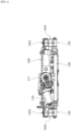
- FIG. 1 to FIG. 5 are views illustrating the structure of a seat suspension mechanism 1 according to this embodiment.
- the seat suspension mechanism 1 supports a seat for a vehicle such as a passenger car, a truck, a bus, or a forklift.
- the seat suspension mechanism 1 includes a lower frame 100 and an upper frame 200.
- the lower frame 100 is fixed to a vehicle floor which is a vehicle structure side and the upper frame 200 is attached to the seat.
- the lower frame 100 fixed to the vehicle floor is substantially square-shaped in plan view and supports the upper frame 200 through a link mechanism 130.
- the link mechanism 130 includes a pair of left and right front links 131, 131 and a pair of left and right rear links 132, 132.
- the front links 131, 131 have lower portions 131a, 131a rotatably supported by side edge portions 100a, 100a of the lower frame 100 at positions close to the front and have upper portions 131b, 131b connected to side frames 203, 203 of the upper frame 200 at positions close to a front frame 201 of the upper frame 200 (see FIG. 3 ).
- the rear links 132, 132 have lower portions 132a, 132a rotatably supported by the side edge portions 100a, 100a of the lower frame 100 at positions close to the rear and have upper portions 132b, 132b connected to the side frames 203, 203 of the upper frame 200 at positions close to a rear frame 202 of the upper frame 200.
- the upper frame 200 is movable up and down relative to the lower frame 100, more accurately, moves up and down along rotation trajectories of the front links 131, 131 and the rear links 132, 132 because the link mechanism 130 is a parallel link structure including the front links 131, 131 and the rear links 132, 132.
- the front links 131, 131 and the rear links 132, 132 are displaced along a direction in which they rotate around the lower portions 131a, 131a, 132a, 132a which are connection center points between the links 131, 132 and the lower frame 100, that is, along a direction in which the front links 131, 131 and the rear links 132, 132 lean forward to go toward a lower limit position (anticlockwise in FIG. 3 ) and along a direction in which they return in the opposite direction to go toward an upper limit position (clockwise direction in FIG. 3 ), and consequently, the upper frame 200 moves up and down.
- a first upper frame-side torsion bar 141a is disposed, and between the connection center points at which the rear links 132, 132 are connected to the side frames 203, 203, a second upper frame-side torsion bar 141b is disposed (see FIG. 3 ).
- the first and second upper frame-side torsion bars 141a, 141b have one-side ends connected to the upper portions 131b, 131b, 132b, 132b of the front links 131, 131 and the rear links 132, 132, and the other ends of the first and second upper frame-side torsion bars 141a, 141b do not rotate relative to the side frames 203, 203 of the upper frame 200.
- a lower frame-side torsion bar 141c is disposed between the lower portions 132a, 132a of the rear links 132, 132.
- the lower frame-side torsion bar 141c has one end connected to the lower portions 132a, 132a of the rear links 132, 132, and the other end of the lower frame-side torsion bar 141c does not rotate relative to the side edge portion 100a of the lower frame 100.
- totally three torsion bars namely, the first and second upper frame-side torsion bars 141a, 141b and the lower frame-side torsion bar 141c constitute a first spring part that exhibits a linear characteristic of changing substantially linearly in its load-deflection characteristic and biases the upper frame 200 in a direction in which the upper frame 200 separates from the lower frame 100.
- the first spring part is combined with a magnetic spring 142 and so on to be described later constituting a second spring part that exhibits, in a predetermined up-down movement range including a balanced point, a spring characteristic of biasing the upper frame 200 in a direction in which the upper frame 200 approaches the lower frame 100.
- the combination of the first spring part and the second spring part constitutes a spring mechanism 140 having a characteristic of having a constant load region in the predetermined displacement range.
- the second spring part of this embodiment includes the magnetic spring 142.
- the magnetic spring 142 includes a stationary magnet unit 1420 and a movable magnet unit 1421.
- the stationary magnet unit 1420 has a pair of stationary magnets 1420a, 1420a fixed to the lower frame 100 and facing each other at a predetermined interval in the width direction of the lower frame 100.
- bipolar magnets whose different poles are adjacent in the up-down direction are used, for instance, and the stationary magnets 1420a, 1420a are arranged with their same poles facing each other.
- the movable magnet unit 1421 has a movable magnet 1421a disposed in a space between the stationary magnets 1420a, 1420a facing each other at the predetermined interval.
- the movable magnet 1421a is magnetized in the up-down direction, for instance, and is supported by a support member 1422, and the support member 1422 is connected to a bracket 1424 fixed to the upper frame 200 to extend downward. Accordingly, when the upper frame 200 moves up/down relative to the lower frame 100, the movable magnet 1421a supported by the support member 1422 is displaced up/down in the space between the stationary magnets 1420a, 1420a.
- the spring characteristic that the magnetic spring 142 exhibits when the movable magnet 1421a moves in the space between the stationary magnets 1420a, 1420a changes depending on the position of the movable magnet 1421a relative to the stationary magnets 1420a, 1420a.
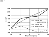
- a positive spring characteristic being defined as a characteristic that restoring force increases in a working direction of elastic force (restoring force) of the three torsion bars, namely, the first and second upper frame-side torsion bars 141a, 141b and the lower frame-side torsion bar 141c which are linear springs, that is, in a direction in which the upper frame 200 separates from the lower frame 100, the magnetic spring 142 exhibits, in its load-deflection characteristic, a negative spring characteristic (the broken-line characteristic in FIG. 7 ) that the restoring force in the aforesaid direction reduces in a predetermined displacement range, as illustrated in FIG. 7 .
- the movable magnet 1421a crosses the boundary between the N poles and the S poles of the two stationary magnets 1420a, 1420a in each of which different poles are adjacent to each other.
- the spring mechanism 140 of this embodiment including the magnetic spring 142 and the above-described three torsion bars, namely, the first and second frame-side torsion bars 141a, 141b and the lower frame-side torsion bar 141c has a small spring constant in the range where the negative spring characteristic of the magnetic spring 142 functions (in the example in FIG. 7 , the range from about -9 mm to about +10 mm).
- the spring characteristic resulting from the superposition of these has a constant load region where a variation in a load value is a predetermined amount or less despite an increase in the displacement amount, that is, a region where the spring constant is substantially zero (preferably, the spring constant falls within a range of about -10 N/mm to about 10 N/mm).
- auxiliary spring mechanisms 143 which constitute, together with the magnetic spring 142, the second spring part exhibiting the negative spring characteristic are preferably provided as in this embodiment.
- the auxiliary spring mechanisms 143 used in this embodiment each include a pantograph link 1430 and a tensile coil spring 1435.
- the pantograph link 1430 includes: two fixed-side links 1431, 1431 which have one-side ends 1431a, 1431a supported by the lower frame 100 and more separate from each other as they go toward their other ends 1431c, 1431c to form a substantially V-shape; and two movable-side links 1432, 1432 which have one-side ends 1432a, 1432a supported by the upper frame 200 and are disposed such that virtual lines connecting the one-side ends 1432a, 1432a and the other ends 1432c, 1432c form a substantially inverted V-shape when the upper frame 200 is at the uppermost end position (the position in FIG. 6(a) ).
- the tensile coil springs 1435 are each suspended between shaft members 1433, 1433 supporting both the other ends 1432c, 1432c of the movable-side links 1432, 1432 and the other ends 1431c, 1431c of the fixed-side links 1431, 1431.
- the orientation of the movable-side links 1432, 1432 of the pantograph link 1430 when the one-side ends 1432a, 1432a of the movable-side links 1432, 1432 are located higher than a straight line connecting the shaft members 1433, 1433 which are engagement support points of the tensile coil spring 1435 (the position in FIG. 6(a) ) is opposite to that when they are located lower than the straight line (the position in FIG. 6(c) ). Accordingly, when the upper frame 200 is at a position (the position in FIG.
- the tensile coil spring 1435 biases the one-side ends 1432a, 1432a of the movable-side links 1432, 1432 upward, and when the upper frame 200 is at a position (the position in FIG. 6(c) ) lower than the predetermined position, the tensile coil spring 1435 biases the one-side ends 1432a, 1432a of the movable-side links 1432, 1432 downward. Therefore, setting the vicinity of the neutral position of the upper frame 200 as a position where the biasing direction by the tensile coil springs 1435 is reversed (the position in FIG.
- auxiliary spring mechanisms 143 make the auxiliary spring mechanisms 143 exhibit the negative spring characteristic of biasing the one-side ends 1432a, 1432a of the movable-side links 1432, 1432 downward in a predetermined displacement range, preferably, in the range where the above-described magnetic spring 142 exhibits the negative spring characteristic (between the positions in FIG. 6(b) and FIG. 6(c) ).
- the second spring part of this embodiment has not only the negative spring characteristic of the magnetic spring 142 but also the characteristic resulting from the superposition of the negative spring characteristic by the auxiliary spring mechanisms 143 which are each the combination of the pantograph link 1430 and the tensile coil spring 1435. Therefore, in spite of the configuration to set the spring force in the positive direction high by disposing the three torsion bars 141a, 141b, 141c exhibiting the positive spring characteristic, this embodiment is capable of creating a constant load region and is capable of coping with a further increase in a load mass. Further, the biasing direction by the auxiliary spring mechanisms 134 switches while the upper frame 200 is within its up-down displacement range as described above.
- the auxiliary spring mechanisms 134 function as braking force to the movements in these directions, and thus are also capable of contributing to an improvement in the impact absorption characteristics.
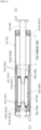
- dampers 150, 160 exhibiting damping force of absorbing energy generated when the lower frame 100 and the upper frame 200 move up and down relative to each other are provided.
- the dampers 150, 160 are telescopic dampers including cylinders 151, 161 and pistons 152, 162 which relatively move in the cylinders 151, 161.
- the dampers 150, 160 are arranged in plurality in parallel and the attachment angles of the dampers 150, 160 are different as in this embodiment.
- the damping force of the damper with a smaller attachment angle has a smaller vertical component, and the damping force acting on the upper frame 200 and the lower frame 100 works more gently than damping force in the case where the attachment angles of all the dampers are the same.
- a configuration having only one damper between the lower frame 100 and the upper frame 200 is of course acceptable.
- the dampers 150, 160 may be typical oil dampers or the like but preferably, movement zones of the pistons 152, 162 in the cylinders 151, 161 which zones correspond to the predetermined up-down movement range including the balanced point when the upper frame 200 moves up and down relative to the lower frame 100 (the balanced point is a position that is set as close to the neutral position of the upper frame 200 as possible when a person seats himself/herself in a static state) are free running zones where substantially no damping force is generated (damping force in the free running zones is very low as compared with damping force in zones other than the free running zones).
- the dampers 150, 160 each having such a free running zone have a dual cylinder structure in which the cylinders 151, 161 include outer fixed cylinders 1511, 1611 and inner movable cylinders 1512, 1612 disposed on the inner sides thereof.
- the pistons 152, 162 are slidable in the inner movable cylinders 1512, 1612.
- the outer fixed cylinders 1511, 1611 have, at their longitudinal-direction ends, stopper portions 1511a, 1511b, 1611a, 1611b, and the inner movable cylinders 1512, 1612, which are shorter in the axial-direction length than the outer fixed cylinders 1511, 1611, are movable until longitudinal-direction ends 1512a, 1512b, 1612a, 1612b of the inner movable cylinders 1512, 1612 abut on the stopper portions 1511a, 1511b, 1611a, 1611b.
- the pistons 152, 162 are movable until their longitudinal-direction ends 152a, 152b, 162a, 162b abut on the stopper portions 1511a, 1511b, 1611a, 1611b.
- the inner movable cylinders 1512, 1612 are longer in the axial-direction length than the pistons 152, 162, and piston rods 153, 163 are connected to the pistons 152, 162.
- string portions 152c, 162c are provided which are formed of wound linear members such as strings and exhibit predetermined friction damping force between themselves and the inner movable cylinders 1512, 1612.
- a viscous fluid such as a grease having a low consistency is made to adhere to the string portions 152c, 162c.
- the viscous fluid can be made to adhere to the linear members such as the strings forming the string portions 152c, 162c by impregnation or coating.
- the frictional force and the viscous damping force to be generated are appropriately controlled by an increase/decrease of the number of turns of the strings forming the string portions 152c, 162c, gaps between adjacent parts of the wound strings, the number of layers of the wound strings, and so on.
- low-friction members 1513, 1613 such as rolling members or sliding members (for example, felts) are interposed so that frictional force between the outer peripheral surfaces of the inner movable cylinders 1512, 1612 and the inner peripheral surfaces of the outer fixed cylinders 1511,1611 becomes relatively smaller than the frictional force generated by the string portions 152c, 162c between the inner movable cylinders 1512, 1612 and the pistons 152, 162.
- the ranges where the inner movable cylinders 1512, 1612 relatively move in the outer fixed cylinders 1511, 1611 are the free running zones where substantially no damping force is generated, and the distance of the free running zones corresponds to a difference in the axial-direction length between the outer fixed cylinders 1511, 1611 and the inner movable cylinders 1512, 1612.
- the pistons 152, 162 do not move relative to the inner movable cylinders 1512, 1612, and the movement zones where no damping force is generated is formed.
- a preferable setting is such that, when the upper frame 200 is at the balanced point (the position adjusted closest possible to the neutral position of the whole stroke where the upper frame 200 is movable up and down) at the time of the up-down movement of the upper frame 200 relative to the lower frame 100 in the seated state, the inner movable cylinders 1512, 1612 are at substantially middle positions of the whole movement ranges in the outer fixed cylinders 1511, 1611. Consequently, the predetermined up-down movement range including the balanced point is formed uniformly above and below the balanced point.
- the dampers 150, 160 exert substantially no damping force, and mainly the spring mechanism 140 takes on the vibration absorption function, and the vibration is damped by phase-shifting from the input vibration.
- the pistons 152, 162 move to positions outside the free running zones, so that the dampers 150, 160 exert the damping force to absorb impact energy.
- the auxiliary spring mechanisms 143 of this embodiment also help absorb the impact energy as described above.
- the seat suspension mechanism 1 of this embodiment exhibits excellent impact absorption characteristics and vibration absorption characteristics, and these characteristics are most excellent when the upper frame 200 is at the balanced point (the position adjusted closest possible to the neutral position of the whole stroke where the upper frame 200 is movable up and down) at the time of the up-down movement of the upper frame 200 relative to the lower frame 100 in the seated state as described above.
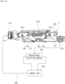
- the seat suspension mechanism 1 of this embodiment has a body weight adjustment mechanism 300 which adjusts the position of the upper frame 200 to the balanced point while a person is supported.
- the body weight adjustment mechanism 300 includes an elastic force adjusting unit 310, a torsion angle detection sensor 320, and a control unit 330.
- the elastic force adjusting unit 310 has a motor 311 and an adjusting member 312 which is put into operation by the motor 311.
- the adjusting member 312 has a rotary shaft 312a rotated by the motor 311 and a rotational force transmission frame 312b moved forward and rearward by the rotation of the rotary shaft 312a and provided substantially in parallel to one of the side frames 203 of the upper frame 200.
- a first engagement plate 312c engaged with the first upper frame-side torsion bar 141a is provided, and at its rear end portion, a second engagement plate 312d engaged with the second upper frame-side torsion bar 141b is provided.
- the rotational force of the motor 311 is transmitted to the rotational force transmission frame 312b through the rotary shaft 312a of the adjusting member 312. This displaces the rotational force transmission frame 312b forward or rearward to cause the forward or rearward rotation of the first engagement plate 312c and the second engagement plate 312d attached to the rotational force transmission frame 312b.
- the rotation of the first engagement plate 312c twists the first upper frame-side torsion bar 141a in either direction
- the rotation of the second engagement plate 312d twists the second upper frame-side torsion bar 141b in either direction. Consequently, the elastic force of the first and second upper frame-side torsion bars 141a, 141b is adjusted.
- the damping force of the dampers 150, 160 which does not practically act near the balanced point as described above, does not become large resistance force in controlling the motor 311, and therefore, a small-sized and small-power motor suffices for the motor 311.
- the torsion angle detection sensor 320 detects a torsion angle of the lower frame-side torsion bar 141c.
- An attachment frame 321 is provided on a rear frame 102 of the lower frame 100, and the torsion angle detection sensor 230 is disposed on the attachment frame 321.
- the torsion angle detection sensor 320 is constituted by, for example, a magnetic circuit sensor and detects the torsion angle from a magnetic field change caused by the twisting of the lower frame-side torsion bar 141c.
- the control unit 330 is attached to, for example, the attachment frame 321 of the seat suspension mechanism 1 (see FIG. 4 ) and includes a CPU and a circuit board on which a storage element and so on are mounted.
- the control unit 330 stores a characteristic of a detection signal of the torsion angle detection sensor 320 corresponding to the torsion angle that the lower frame-side torsion bar 141c has when the upper frame 200 is at the balanced point (balanced point torsion angle 01) (or stores a torsion angle corresponding to the characteristic) in advance.
- the upper frame 200 supporting the weight moves up/down, and accordingly, the link mechanism 130 moves up/down in a manner of depicting an arc around the lower portions 131a, 132a of the links 131, 132.
- the torsion angle detection sensor 320 transmits a detection signal corresponding to this change to the control unit 330.
- the control unit 330 receives the detection signal of the torsion angle detection sensor 320 to find a torsion angle at the current moment (current torsion angle ⁇ 2) corresponding to the characteristic of the detection signal.
- the control unit 330 After finding the current torsion angle ⁇ 2, the control unit 330 compares it with the balanced point torsion angle ⁇ 1 to find a difference therebetween, and according to the difference, performs the control to drive the motor 311 to twist the first and second upper frame-side torsion bars 141a, 141b by a predetermined angle through the adjusting member 312. As a result, the rotation angle of the front links 131 and the rear links 132 of the link mechanism 130 changes, and the current torsion angle ⁇ 2 of the lower frame-side torsion bar 141c becomes equal to the balanced point torsion angle ⁇ 1.
- the sensing-target angle of the lower frame-side torsion bar 141c when the upper frame 200 is at the middle position of the up-down displacement range is 23 degrees, for instance.
- the control unit 330 has stored it as the torsion angle that the lower frame-side torsion bar 141c has when the upper frame 200 is at the balanced point (balanced point torsion angle ⁇ 1).
- a person seats himself/herself on a seat of a vehicle, for example, an automobile, and starts the engine (S1).
- S1 the engine
- his/her weight displaces the upper frame 200 in the up-down direction.
- the control unit 330 preferably drives the motor 311 to make the upper frame 200 present at the uppermost end position (the position in FIG. 6(a) ) (see Step S8 to be described later).
- the displacement amount of the upper frame 200 is large because of the weight of the seated person, and to cope with this, the upper frame 200 is set to the uppermost end position.
- the torsion angle detection sensor 320 detects a signal corresponding to a current torsion angle ⁇ 2 of the lower frame-side torsion bar 141c in the state where the upper frame 200 has been displaced by the person seated (S2).
- the control unit 330 receives the detection signal corresponding to the current torsion angle ⁇ 2 and compares it with the pre-stored balanced point torsion angle ⁇ 1 (S3). In the case where the current torsion angle ⁇ 2 differs from the balanced point torsion angle ⁇ 1, the control unit 330 outputs a control signal according to the difference to the motor 311 of the elastic force adjusting unit 310.
- the rotational force transmission frame 312b is rotated forward or rearward by a predetermined amount through the rotary shaft 312a of the adjusting member 312 according to the rotation amount and the rotation direction of the motor 311, and further the first engagement plate 312c and the second engagement plate 312d rotate forward or rearward by a predetermined amount to twist the first upper frame-side torsion bar 141a and the second upper frame-side torsion bar 141b by a predetermined angle in either direction (S4).
- the control unit 330 causes the torsion angle detection sensor 320 to detect the current torsion angle ⁇ 2 of the lower frame-side torsion bar 141c for several seconds, and monitors how its output changes (S5).
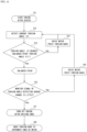
- the control unit 330 In the case where from the result of the monitoring, it turns out that the change in the current torsion angle ⁇ 2 falls out of a predetermined range ("No" at S5), the control unit 330 outputs a control signal to the motor 311 of the elastic force adjusting unit 310 to cause it to twist the first and second upper frame-side torsion bars 141a, 141b in either direction (S6). On the other hand, in the case where the control unit 330 determines at Step S5 that the change in the current torsion angle ⁇ 2 falls within the predetermined range ("Yes" at S5), it does not output the control signal to the motor 311. The above-described steps are repeated, and when the engine is turned off after the driving ends (S7), the control also ends.
- the motor 311 twists the first and second upper frame-side torsion bars 141a, 141b to return the upper frame 200 to the uppermost end position (the position in FIG. 6(a) ) (S8).
- This embodiment includes the body weight adjustment mechanism 300 for automatic adjustment as described above. Therefore, in the initial state when the person seats himself/herself (static state), only by the person seating himself/herself, the upper frame 200 is automatically brought to the neutral position irrespective of his/her weight. This makes it possible to improve vibration absorption characteristics and impact absorption characteristics.
- control unit 330 of the body weight adjustment mechanism 300 constantly monitors the angle of the lower frame-side torsion bar 141c. Then, in the case where the monitored current torsion angle ⁇ 2 differs from the pre-stored balanced point torsion angle ⁇ 1 when the upper frame 200 is at the neutral position (balanced point), the control unit 330 adjusts the torsion angles of the first and second upper frame-side torsion bars 141a, 141b to move the upper frame 200 up or down even during traveling.
- the body weight adjustment mechanism 300 successively obtains the information from the torsion angle detection sensor 320 not only in the static state but also in the dynamic state during traveling, and performs the control to move the seat suspension mechanism 1 up or down to make the current torsion angle ⁇ 2 of the lower frame-side torsion bar 141c agree with the balanced point torsion angle ⁇ 1, thereby constantly guiding the upper frame 200 to the balanced point position (the position in FIG. 6(b) ).
- the upper frame 200 is at the position in FIG.
- the characteristic of the constant load region with a low spring constant which is the characteristic of the spring mechanism 140 composed of the combination of the first spring part and the second spring part, is sufficiently made use of, and owing to the phase shift from the input vibration, high vibration absorption characteristics are obtained.
- the upper frame 200 is always guided to the balanced point position, and therefore, even if impact force is applied, there are sufficient strokes both in the upward and downward directions, and when the upper frame 200 approaches the stroke end, the dampers 150, 160 exhibit higher impact absorption characteristics.
Landscapes
- Engineering & Computer Science (AREA)
- General Engineering & Computer Science (AREA)
- Mechanical Engineering (AREA)
- Aviation & Aerospace Engineering (AREA)
- Transportation (AREA)
- Physics & Mathematics (AREA)
- Acoustics & Sound (AREA)
- Electromagnetism (AREA)
- Seats For Vehicles (AREA)
- Springs (AREA)
- Vibration Prevention Devices (AREA)
Claims (4)
- Sitzaufhängungsmechanismus, der Folgendes umfasst: einen oberen Rahmen (200) und einen unteren Rahmen (100), die gestützt sind, um mit einem Verbindungsmechanismus (130) dazwischen zu einem trennenden und sich annähernden Vorgang relativ zueinander fähig zu sein; und einen Federmechanismus (140), der den oberen Rahmen (200) elastisch vorspannt,
wobei der Federmechanismus (140) Folgendes einschließt:einen ersten Federteil, der den oberen Rahmen (200) in einer Richtung vorspannt, in der sich der obere Rahmen (200) von dem unteren Rahmen (100) trennt; undeinen zweiten Federteil, der, wenn sich der obere Rahmen (200) in einem vorbestimmten Aufwärts-Abwärts-Bewegungsbereich befindet, der einen Gleichgewichtspunkt einschließt, eine Federkennlinie vorweist, die den oberen Rahmen (200) in einer Richtung vorspannt, in der sich der obere Rahmen (200) dem unteren Rahmen (100) annähert, um durch Kombination mit dem ersten Federteil eine Federkennlinie bei konstanter Last zu erschaffen,wobei der Sitzaufhängungsmechanismus weiter einen Körpergewichtseinstellungsmechanismus (300) umfasst, der eine Position des oberen Rahmens (200) in einem Zustand, in dem eine Person gestützt ist, auf den Gleichgewichtspunkt einstellt,wobei der erste Federteil einen unteren rahmenseitigen Torsionsstab (141c), der mit dem unteren Rahmen (100) verbunden ist und durch Bewegung des Verbindungsmechanismus (130) verdreht wird, und einen oberen rahmenseitigen Torsionsstab (141a, b) einschließt, der mit dem oberen Rahmen (200) verbunden ist und durch die Bewegung des Verbindungsmechanismus (130) verdreht wird,wobei der Körpergewichtseinstellungsmechanismus (300) Folgendes einschließt:eine elastische Krafteinstellungseinheit (310), die mit dem oberen rahmenseitigen Torsionsstab (141a, b) verbunden ist und die Position des oberen Rahmens (200) durch Verdrehen des oberen rahmenseitigen Torsionsstabs (141a, b) einstellt;einen Torsionswinkeldetektierungssensor (320), der einen Torsionswinkel des unteren rahmenseitigen Torsionsstabs (141c) detektiert; undeine Steuereinheit (330), die den durch den Torsionswinkeldetektierungssensor (320) detektierten Torsionswinkel des unteren rahmenseitigen Torsionsstabs (141c) mit einem Gleichgewichtspunkt-Torsionswinkel vergleicht, den der untere rahmenseitige Torsionsstab (141c) aufweist, wenn sich der obere Rahmen (200) an dem Gleichgewichtspunkt befindet, und an die elastische Krafteinstellungseinheit (310) ein Steuersignal ausgibt, das anweist, den oberen rahmenseitigen Torsionsstab (141a, b) um einen vorbestimmten Betrag zu verdrehen, um den Torsionswinkel des unteren rahmenseitigen Torsionsstabs (141c) mit dem Gleichgewichtspunkt-Torsionswinkel in Übereinstimmung zu bringen. - Sitzaufhängungsmechanismus nach Anspruch 1, wobei ein Dämpfer (150, 160), dessen Dämpfungskraft in dem vorbestimmten Bereich kleiner ist, der den Gleichgewichtspunkt einschließt, als in einem anderen als dem vorbestimmten Bereich, zwischen dem unteren Rahmen (100) und dem oberen Rahmen (200) aufgehängt ist, und aufgrund dessen, dass die elastische Krafteinstellungseinheit (310) den oberen Rahmen (200) konstant zu dem Gleichgewichtspunkt führt, Eingangsvibration durch Phasensteuerung gedämpft wird.
- Sitzaufhängungsmechanismus nach Anspruch 1 oder 2, wobei der zweite Federteil eine Magnetfeder (142) einschließt, die einen stationären Magneten (1420) und einen beweglichen Magneten (1421) einschließt, dessen Position relativ zu dem stationären Magneten (1420) sich entsprechend der Aufwärts-Abwärts-Bewegung des oberen Rahmens (200) relativ zu dem unteren Rahmen (100) ändert, wobei die Magnetfeder (142) eine nichtlineare Kennlinie einer Änderung der Federkonstante gemäß der Position des beweglichen Magneten (1421) relativ zu dem stationären Magneten (1420) vorweist.
- Sitzaufhängungsmechanismus nach Anspruch 3, wobei der zweite Federteil weiter einen Hilfsfedermechanismus (143) einschließt, der zwischen dem unteren Rahmen (100) und dem oberen Rahmen (200) Folgendes einschließt: eine Storchenschnabelverbindung (1430), die eine bewegungsseitige Verbindung (1432) und eine befestigungsseitige Verbindung (1431) einschließt, deren Verbindungspunkt in einer Vorwärts-Rückwärts-Richtung verschoben ist; und eine Zug-Schraubenfeder (1435), die an der Storchenschnabelverbindung (1430) in der Vorwärts-Rückwärts-Richtung aufgehängt ist, wobei der Hilfsfedermechanismus (143) eine Federkennlinie vorweist, die den oberen Rahmen (200) nach unten vorspannt, wenn sich der obere Rahmen (200) in dem vorbestimmten Aufwärts-Abwärts-Bewegungsbereich befindet, der den Gleichgewichtspunkt einschließt.
Applications Claiming Priority (2)
| Application Number | Priority Date | Filing Date | Title |
|---|---|---|---|
| JP2019192370A JP7412733B2 (ja) | 2019-10-22 | 2019-10-22 | シートサスペンション機構 |
| PCT/JP2020/039739 WO2021079943A1 (ja) | 2019-10-22 | 2020-10-22 | シートサスペンション機構 |
Publications (4)
| Publication Number | Publication Date |
|---|---|
| EP4050233A1 EP4050233A1 (de) | 2022-08-31 |
| EP4050233A4 EP4050233A4 (de) | 2023-01-04 |
| EP4050233C0 EP4050233C0 (de) | 2024-02-21 |
| EP4050233B1 true EP4050233B1 (de) | 2024-02-21 |
Family
ID=75620106
Family Applications (1)
| Application Number | Title | Priority Date | Filing Date |
|---|---|---|---|
| EP20879301.8A Active EP4050233B1 (de) | 2019-10-22 | 2020-10-22 | Sitzaufhängungsmechanismus |
Country Status (4)
| Country | Link |
|---|---|
| US (1) | US12269382B2 (de) |
| EP (1) | EP4050233B1 (de) |
| JP (1) | JP7412733B2 (de) |
| WO (1) | WO2021079943A1 (de) |
Families Citing this family (2)
| Publication number | Priority date | Publication date | Assignee | Title |
|---|---|---|---|---|
| JP2020196328A (ja) * | 2019-05-31 | 2020-12-10 | デルタ工業株式会社 | リンク機構、乗物の上部収容棚構造及びシートサスペンション機構 |
| CN117621959B (zh) * | 2024-01-22 | 2024-04-05 | 无锡持胜车辆部件有限公司 | 一种可体重调节的小尺寸座椅减震装置 |
Family Cites Families (12)
| Publication number | Priority date | Publication date | Assignee | Title |
|---|---|---|---|---|
| JPS6072707U (ja) * | 1983-10-27 | 1985-05-22 | 中央発條株式会社 | ト−シヨンバ−装置 |
| JPH1130274A (ja) * | 1997-05-15 | 1999-02-02 | Delta Tsuuring:Kk | 磁気バネを有する振動機構 |
| JP2003320884A (ja) | 2002-04-26 | 2003-11-11 | Delta Tooling Co Ltd | シートサスペンションの平衡点調節装置 |
| JP4208641B2 (ja) * | 2003-05-29 | 2009-01-14 | 株式会社デルタツーリング | サスペンションユニット |
| US7975813B2 (en) * | 2007-11-27 | 2011-07-12 | Caterpillar Inc. | Electromagnetic suspension system for a seat assembly and machine using same |
| JP5382647B2 (ja) * | 2009-02-03 | 2014-01-08 | 株式会社デルタツーリング | シートサスペンション |
| US9527416B2 (en) * | 2012-05-21 | 2016-12-27 | Sears Manufacturing Co. | Vehicle seat scissors suspension with integrated stabilized isolator |
| US9783086B2 (en) * | 2013-04-23 | 2017-10-10 | Bose Corporation | Seat system for a vehicle |
| DE102014001890B4 (de) * | 2014-02-14 | 2019-08-22 | Grammer Ag | Vorrichtung zum Abfedern eines Federungsoberteils in wenigstens einer Raumrichtung gegenüber einem relativ dazu bewegbaren Federungsunterteil, Sitz und Fahrzeug mit einer derartigen Vorrichtung |
| JP2017210073A (ja) | 2016-05-24 | 2017-11-30 | デルタ工業株式会社 | サスペンション |
| CN110337381B (zh) * | 2016-10-17 | 2022-11-04 | 克利尔运动收购一代有限责任公司 | 主动振动隔离系统 |
| JP6804057B2 (ja) * | 2016-12-09 | 2020-12-23 | デルタ工業株式会社 | サスペンション |
-
2019
- 2019-10-22 JP JP2019192370A patent/JP7412733B2/ja active Active
-
2020
- 2020-10-22 US US17/770,790 patent/US12269382B2/en active Active
- 2020-10-22 WO PCT/JP2020/039739 patent/WO2021079943A1/ja not_active Ceased
- 2020-10-22 EP EP20879301.8A patent/EP4050233B1/de active Active
Also Published As
| Publication number | Publication date |
|---|---|
| JP2021066298A (ja) | 2021-04-30 |
| EP4050233C0 (de) | 2024-02-21 |
| EP4050233A1 (de) | 2022-08-31 |
| WO2021079943A1 (ja) | 2021-04-29 |
| JP7412733B2 (ja) | 2024-01-15 |
| US12269382B2 (en) | 2025-04-08 |
| US20220371487A1 (en) | 2022-11-24 |
| EP4050233A4 (de) | 2023-01-04 |
Similar Documents
| Publication | Publication Date | Title |
|---|---|---|
| EP4049891B1 (de) | Sitzaufhängungsmechanismus | |
| EP4050233B1 (de) | Sitzaufhängungsmechanismus | |
| EP1077157B1 (de) | Schwingungsdämpfungseinrichtung und dazu passender, magnetischer Dämpfungsmechanismus | |
| WO2014175291A1 (ja) | シートサスペンション | |
| EP3552872B1 (de) | Suspension | |
| US11440448B2 (en) | Suspension mechanism, multi-suspension mechanism and damper | |
| US12005820B2 (en) | Seat suspension mechanism | |
| JPH0244583Y2 (de) | ||
| EP3636486A1 (de) | Aufhängungsmechanismus | |
| KR20090006937A (ko) | 차량용 시트의 진동감쇄장치 | |
| JPH0585140A (ja) | 車両用サスペンシヨン | |
| US20220228637A1 (en) | Dampar and seat suspension mechanism | |
| WO2019225543A1 (ja) | サスペンション機構、マルチサスペンション機構及びダンパー | |
| KR102267137B1 (ko) | 차량용 부시 | |
| US20220234482A1 (en) | Link mechanism, vehicle upper storage-rack structure and seat suspension mechanism | |
| JP2557305Y2 (ja) | サスペンションシートの上下位置検出機構 | |
| KR0168107B1 (ko) | 마운팅 인슐레이터의 동작 제어장치 및 그 방법 | |
| WO2017130919A1 (ja) | サスペンション |
Legal Events
| Date | Code | Title | Description |
|---|---|---|---|
| STAA | Information on the status of an ep patent application or granted ep patent |
Free format text: STATUS: THE INTERNATIONAL PUBLICATION HAS BEEN MADE |
|
| PUAI | Public reference made under article 153(3) epc to a published international application that has entered the european phase |
Free format text: ORIGINAL CODE: 0009012 |
|
| STAA | Information on the status of an ep patent application or granted ep patent |
Free format text: STATUS: REQUEST FOR EXAMINATION WAS MADE |
|
| 17P | Request for examination filed |
Effective date: 20220510 |
|
| AK | Designated contracting states |
Kind code of ref document: A1 Designated state(s): AL AT BE BG CH CY CZ DE DK EE ES FI FR GB GR HR HU IE IS IT LI LT LU LV MC MK MT NL NO PL PT RO RS SE SI SK SM TR |
|
| A4 | Supplementary search report drawn up and despatched |
Effective date: 20221202 |
|
| RIC1 | Information provided on ipc code assigned before grant |
Ipc: B60N 2/90 20180101ALI20221128BHEP Ipc: B60N 2/54 20060101ALI20221128BHEP Ipc: B60N 2/50 20060101ALI20221128BHEP Ipc: F16F 15/03 20060101ALI20221128BHEP Ipc: F16F 1/06 20060101ALI20221128BHEP Ipc: F16F 6/00 20060101AFI20221128BHEP |
|
| DAV | Request for validation of the european patent (deleted) | ||
| DAX | Request for extension of the european patent (deleted) | ||
| GRAP | Despatch of communication of intention to grant a patent |
Free format text: ORIGINAL CODE: EPIDOSNIGR1 |
|
| STAA | Information on the status of an ep patent application or granted ep patent |
Free format text: STATUS: GRANT OF PATENT IS INTENDED |
|
| INTG | Intention to grant announced |
Effective date: 20230829 |
|
| GRAS | Grant fee paid |
Free format text: ORIGINAL CODE: EPIDOSNIGR3 |
|
| GRAA | (expected) grant |
Free format text: ORIGINAL CODE: 0009210 |
|
| STAA | Information on the status of an ep patent application or granted ep patent |
Free format text: STATUS: THE PATENT HAS BEEN GRANTED |
|
| RIN1 | Information on inventor provided before grant (corrected) |
Inventor name: OKA, MASARU Inventor name: MASUMURA, SHOGO Inventor name: MAEDA, SHINICHIRO Inventor name: MAKITA, SOICHI Inventor name: FUJITA, ETSUNORI |
|
| AK | Designated contracting states |
Kind code of ref document: B1 Designated state(s): AL AT BE BG CH CY CZ DE DK EE ES FI FR GB GR HR HU IE IS IT LI LT LU LV MC MK MT NL NO PL PT RO RS SE SI SK SM TR |
|
| REG | Reference to a national code |
Ref country code: GB Ref legal event code: FG4D |
|
| REG | Reference to a national code |
Ref country code: CH Ref legal event code: EP |
|
| REG | Reference to a national code |
Ref country code: IE Ref legal event code: FG4D |
|
| REG | Reference to a national code |
Ref country code: DE Ref legal event code: R096 Ref document number: 602020026218 Country of ref document: DE |
|
| U01 | Request for unitary effect filed |
Effective date: 20240223 |
|
| U07 | Unitary effect registered |
Designated state(s): AT BE BG DE DK EE FI FR IT LT LU LV MT NL PT SE SI Effective date: 20240301 |
|
| REG | Reference to a national code |
Ref country code: LT Ref legal event code: MG9D |
|
| PG25 | Lapsed in a contracting state [announced via postgrant information from national office to epo] |
Ref country code: IS Free format text: LAPSE BECAUSE OF FAILURE TO SUBMIT A TRANSLATION OF THE DESCRIPTION OR TO PAY THE FEE WITHIN THE PRESCRIBED TIME-LIMIT Effective date: 20240621 |
|
| PG25 | Lapsed in a contracting state [announced via postgrant information from national office to epo] |
Ref country code: GR Free format text: LAPSE BECAUSE OF FAILURE TO SUBMIT A TRANSLATION OF THE DESCRIPTION OR TO PAY THE FEE WITHIN THE PRESCRIBED TIME-LIMIT Effective date: 20240522 |
|
| PG25 | Lapsed in a contracting state [announced via postgrant information from national office to epo] |
Ref country code: HR Free format text: LAPSE BECAUSE OF FAILURE TO SUBMIT A TRANSLATION OF THE DESCRIPTION OR TO PAY THE FEE WITHIN THE PRESCRIBED TIME-LIMIT Effective date: 20240221 Ref country code: RS Free format text: LAPSE BECAUSE OF FAILURE TO SUBMIT A TRANSLATION OF THE DESCRIPTION OR TO PAY THE FEE WITHIN THE PRESCRIBED TIME-LIMIT Effective date: 20240521 |
|
| PG25 | Lapsed in a contracting state [announced via postgrant information from national office to epo] |
Ref country code: ES Free format text: LAPSE BECAUSE OF FAILURE TO SUBMIT A TRANSLATION OF THE DESCRIPTION OR TO PAY THE FEE WITHIN THE PRESCRIBED TIME-LIMIT Effective date: 20240221 |
|
| PG25 | Lapsed in a contracting state [announced via postgrant information from national office to epo] |
Ref country code: RS Free format text: LAPSE BECAUSE OF FAILURE TO SUBMIT A TRANSLATION OF THE DESCRIPTION OR TO PAY THE FEE WITHIN THE PRESCRIBED TIME-LIMIT Effective date: 20240521 Ref country code: NO Free format text: LAPSE BECAUSE OF FAILURE TO SUBMIT A TRANSLATION OF THE DESCRIPTION OR TO PAY THE FEE WITHIN THE PRESCRIBED TIME-LIMIT Effective date: 20240521 Ref country code: IS Free format text: LAPSE BECAUSE OF FAILURE TO SUBMIT A TRANSLATION OF THE DESCRIPTION OR TO PAY THE FEE WITHIN THE PRESCRIBED TIME-LIMIT Effective date: 20240621 Ref country code: HR Free format text: LAPSE BECAUSE OF FAILURE TO SUBMIT A TRANSLATION OF THE DESCRIPTION OR TO PAY THE FEE WITHIN THE PRESCRIBED TIME-LIMIT Effective date: 20240221 Ref country code: GR Free format text: LAPSE BECAUSE OF FAILURE TO SUBMIT A TRANSLATION OF THE DESCRIPTION OR TO PAY THE FEE WITHIN THE PRESCRIBED TIME-LIMIT Effective date: 20240522 Ref country code: ES Free format text: LAPSE BECAUSE OF FAILURE TO SUBMIT A TRANSLATION OF THE DESCRIPTION OR TO PAY THE FEE WITHIN THE PRESCRIBED TIME-LIMIT Effective date: 20240221 |
|
| PG25 | Lapsed in a contracting state [announced via postgrant information from national office to epo] |
Ref country code: PL Free format text: LAPSE BECAUSE OF FAILURE TO SUBMIT A TRANSLATION OF THE DESCRIPTION OR TO PAY THE FEE WITHIN THE PRESCRIBED TIME-LIMIT Effective date: 20240221 |
|
| PG25 | Lapsed in a contracting state [announced via postgrant information from national office to epo] |
Ref country code: PL Free format text: LAPSE BECAUSE OF FAILURE TO SUBMIT A TRANSLATION OF THE DESCRIPTION OR TO PAY THE FEE WITHIN THE PRESCRIBED TIME-LIMIT Effective date: 20240221 |
|
| PG25 | Lapsed in a contracting state [announced via postgrant information from national office to epo] |
Ref country code: SM Free format text: LAPSE BECAUSE OF FAILURE TO SUBMIT A TRANSLATION OF THE DESCRIPTION OR TO PAY THE FEE WITHIN THE PRESCRIBED TIME-LIMIT Effective date: 20240221 |
|
| PG25 | Lapsed in a contracting state [announced via postgrant information from national office to epo] |
Ref country code: CZ Free format text: LAPSE BECAUSE OF FAILURE TO SUBMIT A TRANSLATION OF THE DESCRIPTION OR TO PAY THE FEE WITHIN THE PRESCRIBED TIME-LIMIT Effective date: 20240221 |
|
| PG25 | Lapsed in a contracting state [announced via postgrant information from national office to epo] |
Ref country code: SK Free format text: LAPSE BECAUSE OF FAILURE TO SUBMIT A TRANSLATION OF THE DESCRIPTION OR TO PAY THE FEE WITHIN THE PRESCRIBED TIME-LIMIT Effective date: 20240221 |
|
| PG25 | Lapsed in a contracting state [announced via postgrant information from national office to epo] |
Ref country code: SM Free format text: LAPSE BECAUSE OF FAILURE TO SUBMIT A TRANSLATION OF THE DESCRIPTION OR TO PAY THE FEE WITHIN THE PRESCRIBED TIME-LIMIT Effective date: 20240221 Ref country code: SK Free format text: LAPSE BECAUSE OF FAILURE TO SUBMIT A TRANSLATION OF THE DESCRIPTION OR TO PAY THE FEE WITHIN THE PRESCRIBED TIME-LIMIT Effective date: 20240221 Ref country code: RO Free format text: LAPSE BECAUSE OF FAILURE TO SUBMIT A TRANSLATION OF THE DESCRIPTION OR TO PAY THE FEE WITHIN THE PRESCRIBED TIME-LIMIT Effective date: 20240221 Ref country code: CZ Free format text: LAPSE BECAUSE OF FAILURE TO SUBMIT A TRANSLATION OF THE DESCRIPTION OR TO PAY THE FEE WITHIN THE PRESCRIBED TIME-LIMIT Effective date: 20240221 |
|
| U20 | Renewal fee for the european patent with unitary effect paid |
Year of fee payment: 5 Effective date: 20241009 |
|
| REG | Reference to a national code |
Ref country code: DE Ref legal event code: R097 Ref document number: 602020026218 Country of ref document: DE |
|
| PLBE | No opposition filed within time limit |
Free format text: ORIGINAL CODE: 0009261 |
|
| STAA | Information on the status of an ep patent application or granted ep patent |
Free format text: STATUS: NO OPPOSITION FILED WITHIN TIME LIMIT |
|
| 26N | No opposition filed |
Effective date: 20241122 |
|
| REG | Reference to a national code |
Ref country code: CH Ref legal event code: PL |
|
| GBPC | Gb: european patent ceased through non-payment of renewal fee |
Effective date: 20241022 |
|
| PG25 | Lapsed in a contracting state [announced via postgrant information from national office to epo] |
Ref country code: MC Free format text: LAPSE BECAUSE OF FAILURE TO SUBMIT A TRANSLATION OF THE DESCRIPTION OR TO PAY THE FEE WITHIN THE PRESCRIBED TIME-LIMIT Effective date: 20240221 |
|
| PG25 | Lapsed in a contracting state [announced via postgrant information from national office to epo] |
Ref country code: GB Free format text: LAPSE BECAUSE OF NON-PAYMENT OF DUE FEES Effective date: 20241022 |
|
| PG25 | Lapsed in a contracting state [announced via postgrant information from national office to epo] |
Ref country code: CH Free format text: LAPSE BECAUSE OF NON-PAYMENT OF DUE FEES Effective date: 20241031 |
|
| PG25 | Lapsed in a contracting state [announced via postgrant information from national office to epo] |
Ref country code: IE Free format text: LAPSE BECAUSE OF NON-PAYMENT OF DUE FEES Effective date: 20241022 |
|
| U20 | Renewal fee for the european patent with unitary effect paid |
Year of fee payment: 6 Effective date: 20251031 |
|
| PG25 | Lapsed in a contracting state [announced via postgrant information from national office to epo] |
Ref country code: CY Free format text: LAPSE BECAUSE OF FAILURE TO SUBMIT A TRANSLATION OF THE DESCRIPTION OR TO PAY THE FEE WITHIN THE PRESCRIBED TIME-LIMIT; INVALID AB INITIO Effective date: 20201022 |
|
| PG25 | Lapsed in a contracting state [announced via postgrant information from national office to epo] |
Ref country code: HU Free format text: LAPSE BECAUSE OF FAILURE TO SUBMIT A TRANSLATION OF THE DESCRIPTION OR TO PAY THE FEE WITHIN THE PRESCRIBED TIME-LIMIT; INVALID AB INITIO Effective date: 20201022 |