EP4049709B1 - Medizinische rohrklemme - Google Patents
Medizinische rohrklemme Download PDFInfo
- Publication number
- EP4049709B1 EP4049709B1 EP20879880.1A EP20879880A EP4049709B1 EP 4049709 B1 EP4049709 B1 EP 4049709B1 EP 20879880 A EP20879880 A EP 20879880A EP 4049709 B1 EP4049709 B1 EP 4049709B1
- Authority
- EP
- European Patent Office
- Prior art keywords
- plate
- protrusion
- clamp
- medical tube
- sloped surface
- Prior art date
- Legal status (The legal status is an assumption and is not a legal conclusion. Google has not performed a legal analysis and makes no representation as to the accuracy of the status listed.)
- Active
Links
Images


Classifications
-
- A—HUMAN NECESSITIES
- A61—MEDICAL OR VETERINARY SCIENCE; HYGIENE
- A61M—DEVICES FOR INTRODUCING MEDIA INTO, OR ONTO, THE BODY; DEVICES FOR TRANSDUCING BODY MEDIA OR FOR TAKING MEDIA FROM THE BODY; DEVICES FOR PRODUCING OR ENDING SLEEP OR STUPOR
- A61M5/00—Devices for bringing media into the body in a subcutaneous, intra-vascular or intramuscular way; Accessories therefor, e.g. filling or cleaning devices, arm rests
- A61M5/14—Infusion devices, e.g. infusing by gravity; Blood infusion; Accessories therefor
- A61M5/168—Means for controlling media flow to the body or for metering media to the body, e.g. drip meters, counters
-
- A—HUMAN NECESSITIES
- A61—MEDICAL OR VETERINARY SCIENCE; HYGIENE
- A61M—DEVICES FOR INTRODUCING MEDIA INTO, OR ONTO, THE BODY; DEVICES FOR TRANSDUCING BODY MEDIA OR FOR TAKING MEDIA FROM THE BODY; DEVICES FOR PRODUCING OR ENDING SLEEP OR STUPOR
- A61M39/00—Tubes, tube connectors, tube couplings, valves, access sites or the like, specially adapted for medical use
- A61M39/22—Valves or arrangement of valves
- A61M39/28—Clamping means for squeezing flexible tubes, e.g. roller clamps
- A61M39/284—Lever clamps
-
- F—MECHANICAL ENGINEERING; LIGHTING; HEATING; WEAPONS; BLASTING
- F16—ENGINEERING ELEMENTS AND UNITS; GENERAL MEASURES FOR PRODUCING AND MAINTAINING EFFECTIVE FUNCTIONING OF MACHINES OR INSTALLATIONS; THERMAL INSULATION IN GENERAL
- F16B—DEVICES FOR FASTENING OR SECURING CONSTRUCTIONAL ELEMENTS OR MACHINE PARTS TOGETHER, e.g. NAILS, BOLTS, CIRCLIPS, CLAMPS, CLIPS OR WEDGES; JOINTS OR JOINTING
- F16B2/00—Friction-grip releasable fastenings
- F16B2/02—Clamps, i.e. with gripping action effected by positive means other than the inherent resistance to deformation of the material of the fastening
- F16B2/06—Clamps, i.e. with gripping action effected by positive means other than the inherent resistance to deformation of the material of the fastening external, i.e. with contracting action
- F16B2/10—Clamps, i.e. with gripping action effected by positive means other than the inherent resistance to deformation of the material of the fastening external, i.e. with contracting action using pivoting jaws
-
- F—MECHANICAL ENGINEERING; LIGHTING; HEATING; WEAPONS; BLASTING
- F16—ENGINEERING ELEMENTS AND UNITS; GENERAL MEASURES FOR PRODUCING AND MAINTAINING EFFECTIVE FUNCTIONING OF MACHINES OR INSTALLATIONS; THERMAL INSULATION IN GENERAL
- F16B—DEVICES FOR FASTENING OR SECURING CONSTRUCTIONAL ELEMENTS OR MACHINE PARTS TOGETHER, e.g. NAILS, BOLTS, CIRCLIPS, CLAMPS, CLIPS OR WEDGES; JOINTS OR JOINTING
- F16B2/00—Friction-grip releasable fastenings
- F16B2/20—Clips, i.e. with gripping action effected solely by the inherent resistance to deformation of the material of the fastening
- F16B2/22—Clips, i.e. with gripping action effected solely by the inherent resistance to deformation of the material of the fastening of resilient material, e.g. rubbery material
-
- F—MECHANICAL ENGINEERING; LIGHTING; HEATING; WEAPONS; BLASTING
- F16—ENGINEERING ELEMENTS AND UNITS; GENERAL MEASURES FOR PRODUCING AND MAINTAINING EFFECTIVE FUNCTIONING OF MACHINES OR INSTALLATIONS; THERMAL INSULATION IN GENERAL
- F16L—PIPES; JOINTS OR FITTINGS FOR PIPES; SUPPORTS FOR PIPES, CABLES OR PROTECTIVE TUBING; MEANS FOR THERMAL INSULATION IN GENERAL
- F16L55/00—Devices or appurtenances for use in, or in connection with, pipes or pipe systems
- F16L55/10—Means for stopping flow in pipes or hoses
Definitions
- the present invention relates to a medical tube clamp, and in particular to a clamp that presses and occludes a flexible medical tube.
- the present invention is defined by the appended claims.
- a flexible medical tube is used as a tube element which is a part of an extracorporeal circulation circuit of a body fluid such as blood, an auxiliary circuit connected to the extracorporeal circulation circuit, an infusion line of medical fluid, or the like.
- the medical tube is equipped with a clamp for pressing and occluding the tube at a desired position.
- a clamp which is made of a resin and which can be manipulated with one hand is known.
- Patent Document 1 discloses a clamp made of a resin, wherein a protrusion that presses a tube is formed on each of opposing surfaces of two plates which are connected to each other, and there is provided a locking unit that fixes the plates at positions at which the plates are closer to each other and that maintains an occluded state of the tube.
- the locking unit fixes (locks) the plates in a state in which the two plates are closer to each other and press the tube, to thereby maintain the occluded state of the tube.
- the clamp disclosed in Patent Document 1 has a centering function to guide the plates to predetermined normal positions so that the plates do not significantly deviate from the predetermined position at which a normal locked state is realized.
- Patent Document 1 WO 2012/111310
- the medical tube is not viewed while being manipulated, the clamp is locked, and the tube is not pressed normally. In this case, an occlusion property of the tube is reduced and leakage is caused.
- the clamp of Patent Document 1 discloses a centering function for guiding the plates to normal positions.
- the clamp of Patent Document 1 it was newly found that, in some cases, when the clamp is used for a tube of a large outer size, the clamp is locked while the centering function fails to be sufficiently realized. Specifically, a tube having a large outer size elastically deforms by the protrusions of the clamp at an early stage in the clamp manipulation.
- a medical tube clamp that presses and occludes a flexible medical tube
- the medical tube clamp comprising: a first plate on which a first protrusion is formed; a second plate placed opposing the first plate, and on which a second protrusion that presses the medical tube along with the first protrusion is formed; a connecting portion that connects one end of the first plate in a length direction and one end of the second plate in a length direction, and that can elastically deform so as to cause the plates to be closer to each other; and a locking unit that is formed extending from the first plate toward the second plate, that locks the other end of the second plate in the length direction, and that maintains an occluded state of the medical tube, wherein a pair of sidewalls that extend in a standing manner are formed on respective ends in the width direction on the first plate, a sloped surface is formed on the second plate, the sloped surface being inclined toward the first plate from both ends in the width direction toward the center in the width direction of the second plate
- a medical tube clamp according to an aspect of the present invention desirably has a structure in which the second plate is inclined with respect to the first plate in an unlocked state so that a spacing between the two plates which press the tube is widened at the other end side in a length direction distanced from the connecting portion.
- the medical tube clamp according to an aspect of the present invention is desirable for a medical tube having a large outer size.
- the medical tube clamp is desirable for a medical tube having an outer size which is equivalent to or larger than a spacing between the first protrusion and the second protrusion of the clamp before assembly; that is, a medical tube in which the first protrusion and the second protrusion of the clamp are in contact with an outer surface of the medical tube in the unlocked state.
- the other end in the length direction of the second plate is pushed toward the first plate so that the spacing between the first protrusion and the second protrusion of the plates is reduced and the tube is pressed.
- the other end in the length direction of the second plate which is pushed is locked by the locking unit, to thereby maintain the locked state in which the tube is occluded.
- the medical tube clamp having the above-described structure
- an inappropriate manipulation such as pushing the second plate in a slanted direction
- the sloped surface of the second plate contacts the side wall of the first plate, and a contact point of the sloped surface with the side wall slides toward an upper end of the sloped surface.
- the second plate moves to an inner side of the clamp. That is, even when an inappropriate manipulation is performed, the second plate can be centered at the normal position at which the tube can be reliably occluded, and the normal locked state can be easily secured. Therefore, with the medical tube clamp having the above-described structure, the medical tube can be occluded quickly and reliably.
- the inclination angle ⁇ of the sloped surface is 10° ⁇ 60°, and the sloped surface is a steeply inclined surface.
- a force in a lateral direction which acts from the inclined surface to the side wall is large.
- the inclination angle ⁇ of the sloped surface is desirably 25° ⁇ 45°, and is more desirably 30° ⁇ 45°.
- a configuration may be employed in which one of the first protrusion and the second protrusion is more sharply pointed than the other of the first protrusion and the second protrusion.
- a medical tube clamp can be provided in which the tube can be more reliably occluded even when an inappropriate manipulation is performed, while securing superior maneuverability.
- the medical tube clamp of the present invention for example, when a manipulation is performed such as pushing the second plate in a slanted direction, the second plate can be centered at the normal position at which the tube can be reliably occluded, and the normal locked state can be easily secured.
- a description of "a numerical value (A) ⁇ a numerical value (B)" means a value of greater than or equal to the numerical value (A) and less than or equal to the numerical value (B).
- a medical tube clamp 10 (hereinafter simply referred to as a "clamp 10") according to an embodiment of the present invention is equipped on a medical tube 1 exemplified in FIG. 3 or the like, but, alternatively, the clamp 10 may be applied to other medical tubes such as a tube having a smaller diameter than the medical tube 1.
- the medical tube on which the clamp 10 is equipped is a part of, for example, an extracorporeal circulation circuit, an auxiliary circuit, an infusion line, or the like.
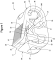
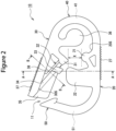
- FIG. 1 is a perspective diagram of the clamp 10, and FIG. 2 is a side view of the clamp 10.
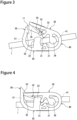
- FIGs. 3 and 4 are diagrams showing states in which the clamp 10 is equipped on the medical tube 1.
- FIG. 3 shows an unlocked state in which the medical tube 1 is not pressed or occluded
- FIG. 4 shows a locked state in which the medical tube 1 is pressed and occluded, and a second plate 30 is locked by a locking unit.
- the clamp 10 is a molded structure made of a resin and having a first plate 20 on which a first protrusion 21 is formed, and the second plate 30 which is placed opposing the first plate 20 and on which is formed a second protrusion 31 which presses the medical tube 1 along with the first protrusion 21.
- the clamp 10 presses and occludes the medical tube 1 with the two plates.
- the second plate 30 is placed opposing the first plate 20 with a gap between the second plate 30 and the first plate 20 through which the medical tube 1 can be passed.
- Each of the first plate 20 and the second plate 30 has an approximate rectangular shape.
- each of one end in a length direction of the first plate 20 and one end in a length direction of the second plate 30 connected by a connection portion 40 to be described below is referred to as a "base end", and each of the other ends in the length direction opposite from the base ends is referred to as a "tip end”.
- the terms base end and tip end are similarly used for the clamp 10.
- a direction along the length direction of each plate will be referred to as a "vertical direction” of the clamp 10
- a direction along a width direction will be referred to as a “lateral direction”
- a direction orthogonal to the vertical direction and the lateral direction will be referred to as an "up-and-down direction”.
- the clamp 10 is equipped at a desired position of the medical tube 1 in a state in which the length direction of each plate is along a length direction of the medical tube 1.
- the clamp 10 has a structure in which a spacing between the first plate 20 and the second plate 30 which press the medical tube 1 is widened at a tip end side of each plate, in an unlocked state in which the medical tube 1 is not occluded.
- a tip end portion of the second plate 30 is pressed toward the first plate 20 to reduce the spacing between the plates, so that a spacing X between the first protrusion 21 and the second protrusion 31 is reduced and the medical tube 1 is occluded.
- the spacing X means a length along the up-and-down direction, from an upper end of the first protrusion 21 to a lower end of the second protrusion 31.
- the clamp 10 has the connecting portion 40 which connects the tip end portions of the first plate 20 and the second plate 30.
- the connecting plate 40 is elastically deformable in the up-and-down direction so as to cause the first plate 20 and the second plate 30 to be closer to each other.
- the connecting portion 40 when the second plate 30 is pressed or the pressing force is released, the spacing X between the first protrusion 21 and the second protrusion 31 changes, and the medical tube 1 is opened or closed.
- the connecting portion 40 largely curves toward an outer side of the clamp 10, and is formed in an approximate U shape in side view.
- the spacing between the first plate 20 and the second plate 30 can be adjusted by changing a length in the up-and-down direction of the connecting portion 40 (diameter of an arc).
- a tube pass-through hole 41 is formed on the connecting portion 40 in a wide area other than respective end portions in the width direction.
- the clamp 10 includes a locking portion 50 formed extending from the first plate 20 toward the second plate 30.
- the locking portion 50 is a locking unit which locks the tip end portion of the second plate 30 and maintains the occluded state of the medical tube 1.
- a hook 52 protruding to an inner side of the clamp 10 is formed, on which the tip end portion of the second plate 30 is hooked.
- a slanted surface inclined toward the inner side of the clamp 10 and in a slanted downward direction is formed at the tip end portion of the locking portion 50, and a lower end of the slanted surface protrudes to the inner side of the clamp 10 to form the hook 52.
- the slanted surface and the hook 52 are formed over the entire width of the locking portion 50.
- the locking portion 50 is a plate-shaped portion extending from the tip of the first plate 20 in the upward direction, and is formed to have the same width as the first plate 20.
- the first plate 20, the second plate 30, the connecting portion 40, and the locking portion 50 are formed to have the same width, and, in the unlocked state and in the normal locked state, center parts of the two plates in the width direction overlap each other in the up-and-down direction.
- the locking portion 50 has a shape in which a base end portion close to the first plate 20 is curved toward the outer side of the clamp 10, and a tip end portion is slightly inclined toward the inner side.
- a tube pass-through hole 51 is formed on the locking portion 50, similar to the connecting portion 40.
- the locking portion 50 elastically deforms in the vertical direction of the clamp 10.
- the tip end portion of the second plate 30 When the tip end portion of the second plate 30 is pushed toward the first plate 20, the tip end portion contacts the slanted surface formed on the tip end portion of the locking portion 50, to thereby elastically deform the locking portion 50 toward the outer side, and the tip end portion moves over the hook 52 and close to the first plate 20.
- the locking portion 50 is restored to its original shape, and, when a hand is moved off from the second plate 30, the tip end portion of the second plate 30 is hooked and locked on the hook 52, and a locked state is realized in which the medical tube 1 is occluded.
- the second plate 30 is released from the hook 52 and the locked state is released.
- the second plate 30 returns to the position of the unlocked state due to a restoration force of the connecting portion 40.
- an opening 11 is formed between the tip end portion of the second plate 30 and the tip end portion of the locking portion 50.
- the opening 11 does not exist, and the first plate 20, the connecting portion 40, the second plate 30, and the locking portion 50 are connected in an annular shape.
- the clamp 10 is equipped on the medical tube 1 by passing the medical tube 1 through the tube pass-through holes 41 and 51 of the connecting portion 40 and the locking portion 50, in a state in which the medical tube 1 is sandwiched between the first plate 20 and the second plate 30.
- the clamp 10 is equipped in such a manner that the medical tube 1 passes through a region between the first protrusion 21 of the first plate 20 and the second protrusion 31 of the second plate 30. Therefore, the spacing X between the first protrusion 21 and the second protrusion 31 is set to be larger than the diameter of the medical tube onto which the clamp is equipped.
- the first plate 20 and the second plate 30, in particular, a structure related to a centering function of the second plate 30, will now be described in detail.
- the first plate 20 and the second plate 30 are pinched from above and below the structure, and pressure is applied to the second plate 30.
- a small unevenness 27 for preventing slippage is formed on the outer surface of the first plate 20.
- the thickness of the first plate 20 is, for example, about 0.5 mm ⁇ 3 mm in a flat portion where there is no large unevenness (this is similarly applicable to the second plate 30).
- the pair of sidewalls 22 is a structure related to the centering function of the second plate 30, and the second plate 30 is centered such that a centering guide 32 to be described below is positioned between the pair of sidewalls 22.
- the sidewalls 22 are desirably formed to be high in a range of not obstructing an appropriate locking manipulation, from the viewpoint of improving the centering function.
- the sidewalls 22 are formed in a thickness within a range of not obstructing an appropriate locking manipulation; that is, in a thickness to not interfere with the centering guide 32 when the pressure is applied on the second plate 30 straight toward the first plate 20.
- the pair of sidewalls 22 are identical in shape and size, and are formed between a tip of the first plate 20 and the first protrusion 21, aligned in the width direction of the first plate 20.
- each of the sidewalls 22 is formed at a side nearer to the tip of the clamp 10 than the second protrusion 31 of the second plate 30, and an upper end of each of the sidewalls 22 is positioned at an upper position than a lower end of the second protrusion 31 in the unlocked state.
- An upper end surface of the sidewall 22 is formed, for example, parallel to the opposing surface 20S of the first plate 20.
- the sidewall 22 also functions as a tube guide for preventing squeezing-out of the medical tube 1 to the lateral direction from between the two plates.
- a sloped surface which is inclined to be closer to the first plate 20 from the ends in the width direction toward the center in the width direction is formed. That is, the sloped surface is inclined with respect to the width direction in such a manner that the ends in the width direction of the second plate 30 are upper ends, and the center in the width direction is the lower end.
- the sloped surface is formed to contact the sidewall 22 of the first plate 20 when an inappropriate locking manipulation is performed such as pushing the second plate 30 in a slanted direction.
- an inappropriate locking manipulation such as pushing the second plate 30 in a slanted direction.
- the sloped surface is desirably formed to be symmetric in the left and right with respect to the center in the width direction of the second plate 30. In this case, the same centering process is applied in cases where the second plate 30 is pushed in a slanted direction to the left and to the right.
- the sloped surface of the present embodiment includes a first sloped surface 33 and a second sloped surface 34 having a smaller inclination angle ⁇ than the first sloped surface 33, and the centering guide 32 is formed from the two sloped surfaces.
- the centering guide 32 (sloped surface) is formed between the tip of the second plate 30 and the second protrusion 31.
- the centering guide may be formed from one sloped surface (for example, only the first sloped surface 33), or may be formed from three or more sloped surfaces having different inclination angles ⁇ from each other.
- the centering guide 32 is formed in a slanted direction with respect to the opposing surface 30S from a region near the tip of the second protrusion 31 protruding toward the first plate 20 to a region near the tip of the second plate 30.
- the opposing surface 30S, the second protrusion 31, and the centering guide 32 are placed to respectively form one side of a triangle.
- a reinforcement rib 38 having an approximate triangular shape in side view is formed.
- the reinforcement rib 38 is formed to be higher toward the second protrusion 31 in the center part in the width direction of the second plate 30.
- a biting-prevention piece 35 protruding toward the first plate 20 is formed on the opposing surface 30S of the second plate 30.
- the biting-prevention piece 35 extends beyond a tip end position of the locking portion 50 toward the first plate 20. Because the opening 11 is formed between the second plate 30 and the locking portion 50 of the clamp 10, for example, a situation may be considered in which, during transport or storage, another clamp 10 enters the inside of the clamp 10, and the clamps cannot be easily separated. With the provision of the biting-prevention piece 35, such a disadvantage can be avoided.
- the biting-prevention piece 35 is formed along the length direction from the tip of the second plate 30 to the second protrusion 31 at the center part in the width direction of the opposing surface 30S. With a connecting portion with the biting-prevention piece 35 on the second sloped surface 34 of the centering guide 32 being a lower end, the second sloped surface 34 is divided by the biting-prevention piece 35 into a one-end side and the other-end side in the width direction of the second plate 30. On the other hand, the lower end of the first sloped surface 33 formed at the center part in the width direction of the opposing surface 30S protrudes beyond a lower end of the biting-prevention piece 35 toward the first plate 20, and is thus not divided by the biting-prevention piece 35. Alternatively, the biting-prevention piece 35 may be omitted.
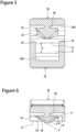
- FIG. 5 is a cross-sectional diagram along a line AA in FIG. 2
- FIG. 6 is a cross-sectional diagram along a line BB in FIG. 2 .
- the centering guide 32 is formed to be positioned at the inside of the pair of sidewalls 22 formed on the first plate 20 in the normal locked state. That is, on the opposing surface 30S of the second plate 30, the centering guide 32 is formed in a region not overlapping the pair of sidewalls 22 in the up-and-down direction. With this configuration, when an appropriate locking manipulation is performed to push the second plate 30 straight, interference between the sidewall 22 and the centering guide 32 is prevented.
- the sloped surface (the first sloped surface 33 and the second sloped surface 34) of the centering guide 32 is inclined by a predetermined angle ⁇ with respect to the width direction of the second plate 30.
- a pair of the first sloped surfaces 33 are provided, forming an approximate V-shaped portion.
- the first sloped surfaces 33 are formed in such a manner that a vertex of the approximate V-shaped portion is positioned at an upper position in relation to the second protrusion 31, so as to reduce influences of the approximate V-shaped portion on the tube during the clamping.
- the sloped surfaces are formed in such a manner that the sloped surfaces can contact the pair of the sidewalls 22 when the spacing X between the first protrusion 21 and the second protrusion 31 is reduced by 10% ⁇ 90%.
- the sloped surface does not contact the sidewalls 22.
- the sloped surfaces are formed in such a manner that the sloped surfaces contact the sidewalls 22 when the second plate 30 is pushed in the direction in which the plates move toward each other in a state in which the second plate 30 is deviated in the lateral direction with respect to the first plate, and the spacing X is reduced by 10% ⁇ 90%.
- Respective ends in the width direction of the first sloped surface 33 and the second sloped surface 34 are desirably placed near a position immediately above the sidewalls 22 in a range not obstructing the appropriate locking manipulation, and, in some configurations, may be formed immediately above the sidewalls 22.
- positions of the respective ends in the width direction of the first sloped surface 33 and the second sloped surface 34 coincide with each other, and the sloped surfaces are formed at a side slightly nearer to the center in the width direction of the second plate 30 than the positions immediately above the sidewalls 22.
- the inclination angle ⁇ of the sloped surface of the centering guide 32 with respect to the width direction of the second plate 30 is 10° ⁇ 60°.
- the inclination angle ⁇ is an angle of the sloped surface with respect to a virtual line ⁇ which is parallel to the width direction of the second plate 30 in a cross section (cross section shown in FIG. 6 ) in which the second plate 30 is cut in the width direction, perpendicular to the lower end of the sloped surface.
- the sloped surface includes the first sloped surface 33 and the second sloped surface 34
- at least the first sloped surface 33 having a steeper inclination is formed with the angle ⁇ of 10° ⁇ 60°, and, desirably, both sloped surfaces are formed with the angle ⁇ of 10° ⁇ 60°.
- the inclination angle ⁇ of the second sloped surface 34 (hereinafter, referred to as an "inclination angle ⁇ 2") is smaller than the inclination angle ⁇ 1 of the first sloped surface 33, and may be, for example, 10° or greater and less than 25°, or 20° or greater and less than 25°.
- the inclination angle ⁇ of the sloped surface is desirably 25° or greater, and is more desirably 30° or greater, similar to the first sloped surface 33.
- the centering guide 32 is formed at a position to contact the sidewall 22 when the second plate 30 is pushed in a slanted direction and the spacing X is reduced by 10% ⁇ 90%, desirably, 30% ⁇ 70%. If the centering guide 32 contacts the sidewall 22 at a stage of a small reduction percentage of the spacing X, the centering process would be performed when the frictional force is relatively small. Thus, with the above-described structure, a situation in which the centering does not function due to the frictional force can be reduced.
- a length in the vertical direction of the first sloped surface 33 is, for example, 10% ⁇ 50% of the length in the vertical direction of the sidewall 22.
- the contact area with the sidewall 22 becomes smaller, resulting in a smaller frictional resistance during the centering, and ease of manipulation.
- the sloped surface does not contact the sidewall 22 when the connecting portion 40 is significantly distorted. Therefore, an appropriate relationship is desirable.
- the centering guide 32 is desirably formed in such a manner that the centering guide 32 contacts the sidewall 22 before the second plate 30 is pushed in the slanted direction and the spacing X is reduced by 50%. In this case, the centering of the second plate 30 can be realized quickly, and the maneuverability is further improved.
- the spacing between the lower end of the first sloped surface 33 and the upper end of the sidewall 22 is, for example, 10% ⁇ 80%, and is desirably 20 % ⁇ 50%, of the spacing X between the first protrusion 21 and the second protrusion 31.
- the first sloped surface 33 protrudes more toward the first plate 20 than the second sloped surface 34 does, when the inappropriate locking manipulation is performed such as pushing the second plate 30 in the slanted direction, the first sloped surface 33 first contacts the sidewall 22.
- the second sloped surface 34 which is formed on the side nearer to the tip of the second plate 30 than the first sloped surface 33 contacts the sidewall 22, and, thus, the second plate 30 is centered using the second sloped surface 34.
- FIG. 7 is a diagram showing a relationship between the inclination angle ⁇ 1 of the first sloped surface 33 and the force necessary for locking the clamp 10 (pressurization force of the second plate 30).
- the pressurization force was measured using a precision universal testing machine autograph ("AG Xplus” manufactured by Shimadzu Corporation).
- AG Xplus manufactured by Shimadzu Corporation
- pressurization forces were measured 5 times for each inclination angle, and average values were determined.
- the shape of the tip portion of the second protrusion 31 which contacts the medical tube 1 was set to a semispherical shape in side view, similar to the first protrusion 21.
- a flexible tube having a diameter similar to the spacing X was used.
- the configuration labeled "Normal” in FIG. 7 indicates a case where the clamp is locked by an appropriate manipulation to push the second plate 30 straight toward the first plate 20.
- the configuration labeled “Abnormal” in FIG. 7 indicates a case where the second plate 30 is pushed in the slanted direction so that a region of the first sloped surface 33 near the lower end contacts the sidewall 22, and the clamp is locked after the centering of the second plate 30.
- the pressurization force is smaller by about 5% than the clamp having ⁇ 1 of 20°, but this difference may be considered to be caused by the shape of the tip end portion of the second protrusion 31.
- the tip end portion of the second protrusion 31 in the approximate V shape in side view, it becomes possible to reduce the force necessary for locking, and to improve maneuverability.
- the pressurization force necessary for locking when the inappropriate locking manipulation is performed is significantly increased, and the centering of the second plate 30 is difficult.
- the second plate 30° can be centered, and, when the inclination angle ⁇ 1 is 25° or greater, in particular, 30° or greater, the pressurization force necessary for the locking is specifically reduced, and the maneuverability is significantly improved.
- FIGs. 8 and 9 are diagrams showing alternative configurations of the first sloped surface 33 of the centering guide 32.
- a first sloped surface 33X exemplified in FIG. 8 is formed to be curved in a manner to be convex down, so that a distance between the sloped surface and the sidewall is reduced, and the centering is performed at an earlier stage when the plate is pushed in the slanted direction.
- a first sloped surface 33Y exemplified in FIG. 9 differs from the first sloped surface 33 formed in a flat shape in that the sloped surface 33Y is curved in a manner to be convex down, and there is a point of change of an angle.
- Each of the first sloped surfaces 33X and 33Y is a convex surface protruding downward in relation to a virtual line ⁇ connecting an upper end P1 and a lower end P2 of the sloped surface in the cross section in which the second plate 30 is cut in the width direction, perpendicular to the lower end of the sloped surface.
- an angle between the virtual line ⁇ parallel to the width direction of the second plate 30 and the virtual line ⁇ is assumed to be the inclination angle ⁇ 1.
- the sloped surface may be a curved or bent concave surface which is convex up.
- the angle between the virtual line ⁇ and a virtual line ⁇ connecting the upper end P1 and the lower end P2 of the sloped surface is assumed to be the inclination angle ⁇ .
- the sloped surface may be a concave surface, but desirably, the sloped surface is a flat surface or a convex surface.
- the first sloped surface 33Y exemplified in FIG. 9 is formed from two flat surfaces S1 and S2 having different inclination angles with respect to the virtual line ⁇ , and desirably, both of the flat surfaces S1 and S2 are inclined by an angle of 25° or greater with respect to the virtual line ⁇ .
- the second plate 30 can be centered at the normal position where the medical tube 1 can be reliably occluded, and the normal locked state can be easily secured. Therefore, with the clamp 10, the medical tube 1 can be quickly and reliably occluded. In addition, even when the clamp 10 is equipped on a medical tube 1 having a large diameter, the centering of the second plate 30 can be easily performed.
- the centering guide 32 including the sloped surface having the inclination angle ⁇ with respect to the width direction of the second plate 30 of 25° ⁇ 45°, and more desirably, 30° ⁇ 45°, the force necessary for the centering of the second plate 30 is significantly reduced, and a smoother centering is enabled.
Landscapes
- Health & Medical Sciences (AREA)
- Engineering & Computer Science (AREA)
- General Engineering & Computer Science (AREA)
- Heart & Thoracic Surgery (AREA)
- Anesthesiology (AREA)
- Biomedical Technology (AREA)
- Hematology (AREA)
- Life Sciences & Earth Sciences (AREA)
- Animal Behavior & Ethology (AREA)
- General Health & Medical Sciences (AREA)
- Public Health (AREA)
- Veterinary Medicine (AREA)
- Mechanical Engineering (AREA)
- Pulmonology (AREA)
- Vascular Medicine (AREA)
- Infusion, Injection, And Reservoir Apparatuses (AREA)
Claims (3)
- Medizinische Schlauchklemme (10), die einen flexiblen medizinischen Schlauch (1) zusammendrückt und verschließt, wobei die medizinische Schlauchklemme (10) umfasst:eine erste Platte (20), auf der ein erster Vorsprung (21) ausgebildet ist;eine zweite Platte (30), die gegenüber der ersten Platte (20) angeordnet ist und auf der ein zweiter Vorsprung (31) ausgebildet ist, der den medizinischen Schlauch (1) zusammen mit dem ersten Vorsprung (21) zusammendrückt;einen Verbindungsabschnitt (40), der ein Ende der ersten Platte (20) in einer Längsrichtung und ein Ende der zweiten Platte (30) in einer Längsrichtung verbindet, und der elastisch verformbar ist, um zu ermöglichen, dass die erste Platte (20) und die zweite Platte (30) näher aneinander sind; undeine Verriegelungseinheit (50), die von der ersten Platte (20) zu der zweiten Platte (30) sich erstreckend ausgebildet ist, die ein anderes Ende der zweiten Platte (30) in der Längsrichtung verriegelt, und die einen verschlossenen Zustand des medizinischen Schlauchs (1) aufrechterhält, wobeiein Paar stehend verlaufende Seitenwände (22) an beiden Enden in einer Breitenrichtung an der ersten Platte (20) ausgebildet sind,ein Beißschutzteil (35) ausgebildet ist, das sich vom anderen Ende der zweiten Platte in Längsrichtung (30) zu dem zweiten Vorsprung (31) entlang der Längsrichtung in einer Mitte in einer Breitenrichtung der zweiten Platte (30) erstreckt, wobei das Beißschutzteil (35) in Richtung der ersten Platte (20) vorsteht,eine schräge Fläche (33) an der zweiten Platte (30) ausgebildet ist, wobei die schräge Fläche (33) in Richtung der ersten Platte (20) von beiden Enden in der Breitenrichtung zur Mitte in der Breitenrichtung der zweiten Platte (30) geneigt ist, undein Neigungswinkel θ der schrägen Fläche (33) in Bezug auf die Breitenrichtung der zweiten Platte (30) 10° - 60° beträgt, und dadurch gekennzeichnet, dassdie schräge Fläche (33) in der Mitte in Breitenrichtung der zweiten Platte (30) über das Beißschutzteil (35) in Richtung der ersten Platte (20) vorsteht.
- Medizinische Schlauchklemme (1) nach Anspruch 1, wobei
der Neigungswinkel θ der schrägen Fläche (33) 25° ∼ 45° beträgt. - Medizinische Schlauchklemme (1) nach Anspruch 1 oder 2, wobei
einer des ersten Vorsprungs (21) und des zweiten Vorsprungs (31) spitzer ist als der andere des ersten Vorsprungs (21) und des zweiten Vorsprungs (31).
Applications Claiming Priority (2)
| Application Number | Priority Date | Filing Date | Title |
|---|---|---|---|
| JP2019194009 | 2019-10-25 | ||
| PCT/JP2020/039878 WO2021079980A1 (ja) | 2019-10-25 | 2020-10-23 | 医療用チューブクランプ |
Publications (3)
| Publication Number | Publication Date |
|---|---|
| EP4049709A1 EP4049709A1 (de) | 2022-08-31 |
| EP4049709A4 EP4049709A4 (de) | 2023-09-27 |
| EP4049709B1 true EP4049709B1 (de) | 2025-04-09 |
Family
ID=75620181
Family Applications (1)
| Application Number | Title | Priority Date | Filing Date |
|---|---|---|---|
| EP20879880.1A Active EP4049709B1 (de) | 2019-10-25 | 2020-10-23 | Medizinische rohrklemme |
Country Status (3)
| Country | Link |
|---|---|
| EP (1) | EP4049709B1 (de) |
| JP (2) | JP7480784B2 (de) |
| WO (1) | WO2021079980A1 (de) |
Family Cites Families (11)
| Publication number | Priority date | Publication date | Assignee | Title |
|---|---|---|---|---|
| DE9310226U1 (de) * | 1993-07-09 | 1993-09-30 | Spang & Brands GmbH, 61381 Friedrichsdorf | Schlauchklemme |
| US5951519A (en) * | 1997-04-25 | 1999-09-14 | Dsu Medical Corporation | Aseptic female connector |
| US6089527A (en) * | 1997-10-03 | 2000-07-18 | Medisystems Technology Corporation | Squeeze clamp for flexible tubing |
| EP2007474B1 (de) * | 2006-04-05 | 2018-12-05 | Noble House Group Pty. Ltd. | Nicht wiederöffnende arretierquetschklemme für schläuche |
| US8025645B2 (en) * | 2007-05-25 | 2011-09-27 | Medical Components, Inc. | Guard for flexible tubing clamp and method of using same |
| CN103391792B (zh) * | 2011-02-17 | 2016-03-16 | 尼普洛株式会社 | 医疗管夹 |
| DE102011110474A1 (de) * | 2011-07-29 | 2013-01-31 | Fresenius Medical Care Deutschland Gmbh | Haltevorrichtung zum Halten wenigstens einer Schlauchklemme an einem medizinischen Schlauch, medizinischer Schlauch sowie Verfahren zum Sterilisieren eines medizinischen Schlauchs |
| JP6052030B2 (ja) * | 2013-04-08 | 2016-12-27 | ニプロ株式会社 | 医療チューブ用クランプ |
| WO2015064233A1 (ja) * | 2013-10-29 | 2015-05-07 | ニプロ株式会社 | クランプ |
| JP6082433B2 (ja) * | 2015-06-22 | 2017-02-15 | 日機装株式会社 | クランプ装置 |
| US11040186B2 (en) * | 2015-10-28 | 2021-06-22 | Becton, Dickinson And Company | Pinch clamp device |
-
2020
- 2020-10-23 EP EP20879880.1A patent/EP4049709B1/de active Active
- 2020-10-23 JP JP2021553556A patent/JP7480784B2/ja active Active
- 2020-10-23 WO PCT/JP2020/039878 patent/WO2021079980A1/ja not_active Ceased
-
2024
- 2024-04-19 JP JP2024068452A patent/JP7639973B2/ja active Active
Also Published As
| Publication number | Publication date |
|---|---|
| JPWO2021079980A1 (de) | 2021-04-29 |
| EP4049709A1 (de) | 2022-08-31 |
| EP4049709A4 (de) | 2023-09-27 |
| JP2024086969A (ja) | 2024-06-28 |
| WO2021079980A1 (ja) | 2021-04-29 |
| JP7480784B2 (ja) | 2024-05-10 |
| JP7639973B2 (ja) | 2025-03-05 |
Similar Documents
| Publication | Publication Date | Title |
|---|---|---|
| CN103391792B (zh) | 医疗管夹 | |
| US8267370B2 (en) | Clamp for flexible tubing | |
| US9015912B2 (en) | Side release buckle | |
| JP4922246B2 (ja) | ワンタッチクランプ装置 | |
| US20170012368A1 (en) | Push-in Clamp Retainer, Push-in Clamp Assembly and Electric Connector Element | |
| JP7592142B2 (ja) | ピンチクランプ | |
| WO2014141387A1 (ja) | バックル | |
| US20220117362A1 (en) | Plug for buckle, and buckle | |
| US20190037973A1 (en) | Buckle | |
| KR100578255B1 (ko) | 2중 와류형 클램프 쇠장식 | |
| EP4049709A1 (de) | Medizinische rohrklemme | |
| WO2024016824A1 (zh) | 扣夹组件和电子装置 | |
| JP2023073275A (ja) | 医療用チューブクランプ | |
| CN106102792B (zh) | 具有对准闩锁且具有改进的耐倾斜性的流体盒、以及血液治疗设备 | |
| US10008806B2 (en) | Lever-type connector capable of operability | |
| JP7499065B2 (ja) | クランプ | |
| JP6290496B1 (ja) | ワンタッチクランプ装置 | |
| JP7437604B2 (ja) | クランプ | |
| CN115485012B (zh) | 夹紧件 | |
| JP7256955B2 (ja) | 医療チューブ用クランプ | |
| JP3717223B2 (ja) | 電線束クランプ | |
| KR200430659Y1 (ko) | 리셉터클 터미널 | |
| JP7510383B2 (ja) | ヒューズプラー | |
| US20240299727A1 (en) | Extracorporeal circulation circuit | |
| JP2005169146A (ja) | クランプ及び医療用具 |
Legal Events
| Date | Code | Title | Description |
|---|---|---|---|
| STAA | Information on the status of an ep patent application or granted ep patent |
Free format text: STATUS: THE INTERNATIONAL PUBLICATION HAS BEEN MADE |
|
| PUAI | Public reference made under article 153(3) epc to a published international application that has entered the european phase |
Free format text: ORIGINAL CODE: 0009012 |
|
| STAA | Information on the status of an ep patent application or granted ep patent |
Free format text: STATUS: REQUEST FOR EXAMINATION WAS MADE |
|
| 17P | Request for examination filed |
Effective date: 20220518 |
|
| AK | Designated contracting states |
Kind code of ref document: A1 Designated state(s): AL AT BE BG CH CY CZ DE DK EE ES FI FR GB GR HR HU IE IS IT LI LT LU LV MC MK MT NL NO PL PT RO RS SE SI SK SM TR |
|
| DAV | Request for validation of the european patent (deleted) | ||
| DAX | Request for extension of the european patent (deleted) | ||
| A4 | Supplementary search report drawn up and despatched |
Effective date: 20230828 |
|
| RIC1 | Information provided on ipc code assigned before grant |
Ipc: F16L 55/10 20060101ALI20230822BHEP Ipc: F16B 2/10 20060101ALI20230822BHEP Ipc: F16L 33/02 20060101ALI20230822BHEP Ipc: F16B 2/22 20060101ALI20230822BHEP Ipc: A61M 5/168 20060101ALI20230822BHEP Ipc: A61M 39/28 20060101AFI20230822BHEP |
|
| GRAP | Despatch of communication of intention to grant a patent |
Free format text: ORIGINAL CODE: EPIDOSNIGR1 |
|
| STAA | Information on the status of an ep patent application or granted ep patent |
Free format text: STATUS: GRANT OF PATENT IS INTENDED |
|
| INTG | Intention to grant announced |
Effective date: 20241106 |
|
| GRAS | Grant fee paid |
Free format text: ORIGINAL CODE: EPIDOSNIGR3 |
|
| GRAA | (expected) grant |
Free format text: ORIGINAL CODE: 0009210 |
|
| STAA | Information on the status of an ep patent application or granted ep patent |
Free format text: STATUS: THE PATENT HAS BEEN GRANTED |
|
| AK | Designated contracting states |
Kind code of ref document: B1 Designated state(s): AL AT BE BG CH CY CZ DE DK EE ES FI FR GB GR HR HU IE IS IT LI LT LU LV MC MK MT NL NO PL PT RO RS SE SI SK SM TR |
|
| REG | Reference to a national code |
Ref country code: GB Ref legal event code: FG4D |
|
| REG | Reference to a national code |
Ref country code: CH Ref legal event code: EP |
|
| REG | Reference to a national code |
Ref country code: DE Ref legal event code: R096 Ref document number: 602020049303 Country of ref document: DE |
|
| REG | Reference to a national code |
Ref country code: IE Ref legal event code: FG4D |
|
| REG | Reference to a national code |
Ref country code: NL Ref legal event code: MP Effective date: 20250409 |
|
| PG25 | Lapsed in a contracting state [announced via postgrant information from national office to epo] |
Ref country code: NL Free format text: LAPSE BECAUSE OF FAILURE TO SUBMIT A TRANSLATION OF THE DESCRIPTION OR TO PAY THE FEE WITHIN THE PRESCRIBED TIME-LIMIT Effective date: 20250409 |
|
| REG | Reference to a national code |
Ref country code: AT Ref legal event code: MK05 Ref document number: 1783019 Country of ref document: AT Kind code of ref document: T Effective date: 20250409 |
|
| PG25 | Lapsed in a contracting state [announced via postgrant information from national office to epo] |
Ref country code: PT Free format text: LAPSE BECAUSE OF FAILURE TO SUBMIT A TRANSLATION OF THE DESCRIPTION OR TO PAY THE FEE WITHIN THE PRESCRIBED TIME-LIMIT Effective date: 20250811 Ref country code: ES Free format text: LAPSE BECAUSE OF FAILURE TO SUBMIT A TRANSLATION OF THE DESCRIPTION OR TO PAY THE FEE WITHIN THE PRESCRIBED TIME-LIMIT Effective date: 20250409 Ref country code: FI Free format text: LAPSE BECAUSE OF FAILURE TO SUBMIT A TRANSLATION OF THE DESCRIPTION OR TO PAY THE FEE WITHIN THE PRESCRIBED TIME-LIMIT Effective date: 20250409 |
|
| REG | Reference to a national code |
Ref country code: LT Ref legal event code: MG9D |
|
| PG25 | Lapsed in a contracting state [announced via postgrant information from national office to epo] |
Ref country code: GR Free format text: LAPSE BECAUSE OF FAILURE TO SUBMIT A TRANSLATION OF THE DESCRIPTION OR TO PAY THE FEE WITHIN THE PRESCRIBED TIME-LIMIT Effective date: 20250710 Ref country code: NO Free format text: LAPSE BECAUSE OF FAILURE TO SUBMIT A TRANSLATION OF THE DESCRIPTION OR TO PAY THE FEE WITHIN THE PRESCRIBED TIME-LIMIT Effective date: 20250709 |
|
| PG25 | Lapsed in a contracting state [announced via postgrant information from national office to epo] |
Ref country code: PL Free format text: LAPSE BECAUSE OF FAILURE TO SUBMIT A TRANSLATION OF THE DESCRIPTION OR TO PAY THE FEE WITHIN THE PRESCRIBED TIME-LIMIT Effective date: 20250409 |
|
| PG25 | Lapsed in a contracting state [announced via postgrant information from national office to epo] |
Ref country code: BG Free format text: LAPSE BECAUSE OF FAILURE TO SUBMIT A TRANSLATION OF THE DESCRIPTION OR TO PAY THE FEE WITHIN THE PRESCRIBED TIME-LIMIT Effective date: 20250409 |
|
| PG25 | Lapsed in a contracting state [announced via postgrant information from national office to epo] |
Ref country code: HR Free format text: LAPSE BECAUSE OF FAILURE TO SUBMIT A TRANSLATION OF THE DESCRIPTION OR TO PAY THE FEE WITHIN THE PRESCRIBED TIME-LIMIT Effective date: 20250409 |
|
| PG25 | Lapsed in a contracting state [announced via postgrant information from national office to epo] |
Ref country code: AT Free format text: LAPSE BECAUSE OF FAILURE TO SUBMIT A TRANSLATION OF THE DESCRIPTION OR TO PAY THE FEE WITHIN THE PRESCRIBED TIME-LIMIT Effective date: 20250409 |
|
| PG25 | Lapsed in a contracting state [announced via postgrant information from national office to epo] |
Ref country code: RS Free format text: LAPSE BECAUSE OF FAILURE TO SUBMIT A TRANSLATION OF THE DESCRIPTION OR TO PAY THE FEE WITHIN THE PRESCRIBED TIME-LIMIT Effective date: 20250709 |
|
| PG25 | Lapsed in a contracting state [announced via postgrant information from national office to epo] |
Ref country code: IS Free format text: LAPSE BECAUSE OF FAILURE TO SUBMIT A TRANSLATION OF THE DESCRIPTION OR TO PAY THE FEE WITHIN THE PRESCRIBED TIME-LIMIT Effective date: 20250809 |
|
| PG25 | Lapsed in a contracting state [announced via postgrant information from national office to epo] |
Ref country code: LV Free format text: LAPSE BECAUSE OF FAILURE TO SUBMIT A TRANSLATION OF THE DESCRIPTION OR TO PAY THE FEE WITHIN THE PRESCRIBED TIME-LIMIT Effective date: 20250409 |
|
| PGFP | Annual fee paid to national office [announced via postgrant information from national office to epo] |
Ref country code: DE Payment date: 20251021 Year of fee payment: 6 |
|
| PGFP | Annual fee paid to national office [announced via postgrant information from national office to epo] |
Ref country code: GB Payment date: 20251022 Year of fee payment: 6 |
|
| REG | Reference to a national code |
Ref country code: DE Ref legal event code: R097 Ref document number: 602020049303 Country of ref document: DE |
|
| PG25 | Lapsed in a contracting state [announced via postgrant information from national office to epo] |
Ref country code: SM Free format text: LAPSE BECAUSE OF FAILURE TO SUBMIT A TRANSLATION OF THE DESCRIPTION OR TO PAY THE FEE WITHIN THE PRESCRIBED TIME-LIMIT Effective date: 20250409 Ref country code: DK Free format text: LAPSE BECAUSE OF FAILURE TO SUBMIT A TRANSLATION OF THE DESCRIPTION OR TO PAY THE FEE WITHIN THE PRESCRIBED TIME-LIMIT Effective date: 20250409 |
|
| PGFP | Annual fee paid to national office [announced via postgrant information from national office to epo] |
Ref country code: FR Payment date: 20251030 Year of fee payment: 6 |
|
| PG25 | Lapsed in a contracting state [announced via postgrant information from national office to epo] |
Ref country code: CZ Free format text: LAPSE BECAUSE OF FAILURE TO SUBMIT A TRANSLATION OF THE DESCRIPTION OR TO PAY THE FEE WITHIN THE PRESCRIBED TIME-LIMIT Effective date: 20250409 |
|
| PG25 | Lapsed in a contracting state [announced via postgrant information from national office to epo] |
Ref country code: EE Free format text: LAPSE BECAUSE OF FAILURE TO SUBMIT A TRANSLATION OF THE DESCRIPTION OR TO PAY THE FEE WITHIN THE PRESCRIBED TIME-LIMIT Effective date: 20250409 |
|
| PG25 | Lapsed in a contracting state [announced via postgrant information from national office to epo] |
Ref country code: SK Free format text: LAPSE BECAUSE OF FAILURE TO SUBMIT A TRANSLATION OF THE DESCRIPTION OR TO PAY THE FEE WITHIN THE PRESCRIBED TIME-LIMIT Effective date: 20250409 |
|
| PG25 | Lapsed in a contracting state [announced via postgrant information from national office to epo] |
Ref country code: IT Free format text: LAPSE BECAUSE OF FAILURE TO SUBMIT A TRANSLATION OF THE DESCRIPTION OR TO PAY THE FEE WITHIN THE PRESCRIBED TIME-LIMIT Effective date: 20250409 |
|
| PG25 | Lapsed in a contracting state [announced via postgrant information from national office to epo] |
Ref country code: RO Free format text: LAPSE BECAUSE OF FAILURE TO SUBMIT A TRANSLATION OF THE DESCRIPTION OR TO PAY THE FEE WITHIN THE PRESCRIBED TIME-LIMIT Effective date: 20250409 |
|
| PLBE | No opposition filed within time limit |
Free format text: ORIGINAL CODE: 0009261 |
|
| STAA | Information on the status of an ep patent application or granted ep patent |
Free format text: STATUS: NO OPPOSITION FILED WITHIN TIME LIMIT |
|
| REG | Reference to a national code |
Ref country code: CH Ref legal event code: L10 Free format text: ST27 STATUS EVENT CODE: U-0-0-L10-L00 (AS PROVIDED BY THE NATIONAL OFFICE) Effective date: 20260218 |
|
| 26N | No opposition filed |
Effective date: 20260112 |
|
| REG | Reference to a national code |
Ref country code: CH Ref legal event code: H13 Free format text: ST27 STATUS EVENT CODE: U-0-0-H10-H13 (AS PROVIDED BY THE NATIONAL OFFICE) Effective date: 20260527 |
|
| PG25 | Lapsed in a contracting state [announced via postgrant information from national office to epo] |
Ref country code: LU Free format text: LAPSE BECAUSE OF NON-PAYMENT OF DUE FEES Effective date: 20251023 |
|
| REG | Reference to a national code |
Ref country code: BE Ref legal event code: MM Effective date: 20251031 |
|
| PG25 | Lapsed in a contracting state [announced via postgrant information from national office to epo] |
Ref country code: LT Free format text: LAPSE BECAUSE OF FAILURE TO SUBMIT A TRANSLATION OF THE DESCRIPTION OR TO PAY THE FEE WITHIN THE PRESCRIBED TIME-LIMIT Effective date: 20250409 |
|
| PG25 | Lapsed in a contracting state [announced via postgrant information from national office to epo] |
Ref country code: MC Free format text: LAPSE BECAUSE OF FAILURE TO SUBMIT A TRANSLATION OF THE DESCRIPTION OR TO PAY THE FEE WITHIN THE PRESCRIBED TIME-LIMIT Effective date: 20250409 |
|
| PG25 | Lapsed in a contracting state [announced via postgrant information from national office to epo] |
Ref country code: CH Free format text: LAPSE BECAUSE OF NON-PAYMENT OF DUE FEES Effective date: 20251031 Ref country code: BE Free format text: LAPSE BECAUSE OF NON-PAYMENT OF DUE FEES Effective date: 20251031 |
|
| PG25 | Lapsed in a contracting state [announced via postgrant information from national office to epo] |
Ref country code: SE Free format text: LAPSE BECAUSE OF FAILURE TO SUBMIT A TRANSLATION OF THE DESCRIPTION OR TO PAY THE FEE WITHIN THE PRESCRIBED TIME-LIMIT Effective date: 20250409 |