EP4048848B1 - Beschlaganordnung - Google Patents
Beschlaganordnung Download PDFInfo
- Publication number
- EP4048848B1 EP4048848B1 EP20833744.4A EP20833744A EP4048848B1 EP 4048848 B1 EP4048848 B1 EP 4048848B1 EP 20833744 A EP20833744 A EP 20833744A EP 4048848 B1 EP4048848 B1 EP 4048848B1
- Authority
- EP
- European Patent Office
- Prior art keywords
- bayonet
- pin
- coupling position
- bolt
- bearing
- Prior art date
- Legal status (The legal status is an assumption and is not a legal conclusion. Google has not performed a legal analysis and makes no representation as to the accuracy of the status listed.)
- Active
Links
Images


Classifications
-
- E—FIXED CONSTRUCTIONS
- E05—LOCKS; KEYS; WINDOW OR DOOR FITTINGS; SAFES
- E05D—HINGES OR SUSPENSION DEVICES FOR DOORS, WINDOWS OR WINGS
- E05D15/00—Suspension arrangements for wings
- E05D15/48—Suspension arrangements for wings allowing alternative movements
- E05D15/52—Suspension arrangements for wings allowing alternative movements for opening about a vertical as well as a horizontal axis
- E05D15/5205—Suspension arrangements for wings allowing alternative movements for opening about a vertical as well as a horizontal axis with horizontally-extending checks
-
- E—FIXED CONSTRUCTIONS
- E05—LOCKS; KEYS; WINDOW OR DOOR FITTINGS; SAFES
- E05Y—INDEXING SCHEME ASSOCIATED WITH SUBCLASSES E05D AND E05F, RELATING TO CONSTRUCTION ELEMENTS, ELECTRIC CONTROL, POWER SUPPLY, POWER SIGNAL OR TRANSMISSION, USER INTERFACES, MOUNTING OR COUPLING, DETAILS, ACCESSORIES, AUXILIARY OPERATIONS NOT OTHERWISE PROVIDED FOR, APPLICATION THEREOF
- E05Y2600/00—Mounting or coupling arrangements for elements provided for in this subclass
- E05Y2600/50—Mounting methods; Positioning
- E05Y2600/52—Toolless
- E05Y2600/528—Hooking, e.g. using bayonets; Locking
-
- E—FIXED CONSTRUCTIONS
- E05—LOCKS; KEYS; WINDOW OR DOOR FITTINGS; SAFES
- E05Y—INDEXING SCHEME ASSOCIATED WITH SUBCLASSES E05D AND E05F, RELATING TO CONSTRUCTION ELEMENTS, ELECTRIC CONTROL, POWER SUPPLY, POWER SIGNAL OR TRANSMISSION, USER INTERFACES, MOUNTING OR COUPLING, DETAILS, ACCESSORIES, AUXILIARY OPERATIONS NOT OTHERWISE PROVIDED FOR, APPLICATION THEREOF
- E05Y2800/00—Details, accessories and auxiliary operations not otherwise provided for
- E05Y2800/15—Applicability
- E05Y2800/17—Universally applicable
- E05Y2800/172—Universally applicable on different wing or frame locations
- E05Y2800/174—Universally applicable on different wing or frame locations on the left or right side
-
- E—FIXED CONSTRUCTIONS
- E05—LOCKS; KEYS; WINDOW OR DOOR FITTINGS; SAFES
- E05Y—INDEXING SCHEME ASSOCIATED WITH SUBCLASSES E05D AND E05F, RELATING TO CONSTRUCTION ELEMENTS, ELECTRIC CONTROL, POWER SUPPLY, POWER SIGNAL OR TRANSMISSION, USER INTERFACES, MOUNTING OR COUPLING, DETAILS, ACCESSORIES, AUXILIARY OPERATIONS NOT OTHERWISE PROVIDED FOR, APPLICATION THEREOF
- E05Y2900/00—Application of doors, windows, wings or fittings thereof
- E05Y2900/10—Application of doors, windows, wings or fittings thereof for buildings or parts thereof
- E05Y2900/13—Type of wing
- E05Y2900/148—Windows
Definitions
- the invention relates to a fitting arrangement for the sash of a window, a door or the like, in particular for a sash that can be opened in a tilt-turn manner.
- Such a fitting arrangement can movably mount the sash on a frame of the window or door.
- the fitting arrangement is attached to the sash and corresponding counterparts are attached to the frame on the so-called hinge side of the window or door, on which the fitting arrangement can then be movably, in particular pivotably, mounted by means of a bearing band.
- the fitting arrangement can, for example, comprise an elongated pivot arm which is attached to the sash and is connected at its hinge-side end via the bearing band to a pivot bearing to be provided on the frame, for example by hooking the bearing band onto the pivot bearing, so that the pivot arm and with it the sash are held by the pivot bearing, but at the same time can be moved, in particular pivoted about an axis of rotation defined by the pivot bearing.
- a so-called hinge angle which can be angled once or several times, comes into consideration as the bearing band.
- a so-called scissor arm is used as a swivel arm, which enables the side of the sash on which it is intended to be positioned to be able to pivot in relation to a position that is only aligned radially to the respective bearing. to be extended parallel so that the sash is tilted to its opposite side.
- the swivel arm mentioned can also be designed as a pure hinge arm or a pure tilt arm (or a hinge arm or tilt arm) or enable other kinematics of the sash in relation to the frame.
- the same variability as with the swivel arms is not required for the swivel bearings, especially for the so-called scissor bearings, which are typically provided at the top of the respective hinge side of the sash. This is because they generally only have to enable the respective swivel arm to swivel and are therefore essentially independent of the shape of the sash and the way it can be opened.
- the bearing band via which a swivel arm is mounted on a swivel bearing, can therefore be designed in the same way for different swivel arms.
- the bearing bands are advisable not to manufacture as an integral part of the swivel arms, but as separate parts, which are then each firmly connected to a swivel arm. In this way, different swivel arms can be manufactured, but each of them has the same bearing band.
- a respective swivel arm is not predetermined as to where the hinge side of the sash is, i.e. which side the sash can be swiveled around.
- a respective swivel arm can in principle be used on both left- and right-opening sashes. Only by coupling it with a bearing hinge is the swivel arm then fixed to a specific hinge side. This determination can result from the choice of bearing hinge and/or the type of arrangement of the bearing hinge on the swivel arm. In the latter case, the fitting arrangement can also be changed by changing the orientation of the bearing hinge on the swivel arm. be reconfigurable. This allows the fitting arrangement to be used particularly flexibly.
- the swivel arm typically extends radially to the axis of rotation and is therefore attached to one of the sides of the sash that is perpendicular to the hinge side.
- the bearing band on the other hand, is usually arranged on the hinge side of the sash so that it can interact with the swivel bearing. It is therefore useful if the swivel arm has a carrying bracket on its hinge-side end that includes a leg that is angled relative to the rest of the swivel arm and can be used to couple it to the bearing band.
- the bearing band can simply be screwed or riveted to the angled leg of the carrying handle.
- this type of coupling requires the use of tools and therefore means additional work when assembling the fitting arrangement.
- a riveted connection is also irreversible, so that the fitting arrangement can no longer be reconfigured if the wrong swivel arm is selected or the wrong hinge side is set.
- a type of connection that is easy to close, yet reliable and can also be released again can be made possible by means of a bayonet lock.
- a bayonet mount is provided on the carrying handle of the swivel arm and on a coupling section of the bearing band a rotating bayonet bolt is provided. This allows the carrying handle and the bearing band to be inserted into one another and secured to one another by rotating the bayonet bolt in the bayonet mount.
- a disadvantage of this type of connection is that tools may be required to turn the bayonet bolt, which is typically difficult to grip. There is also the risk that the rotating bayonet bolt will turn back over time, for example due to the operation of the sash or due to vibrations, and the connection will therefore come loose.
- the fitting arrangement according to the invention for the sash of a window, a door or the like comprises a swivel arm which is designed to be attached to the sash and which has a support bracket with a leg angled transversely to the longitudinal extension at a hinge-side end of its longitudinal extension.
- the sash can in particular be a tilt-turn sash.
- the swivel arm can for this purpose in particular be designed as a scissor arm.
- the swivel arm has in particular an elongated shape which extends between the said end on the belt side and an opposite end remote from the belt. The two ends define a longitudinal axis of the swivel arm, along which the said longitudinal extension is defined.
- the carrying handle with the leg that is angled relative to the rest of the length of the swivel arm can basically be designed as a structural unit with the swivel arm.
- the carrying handle can correspond to a section of the swivel arm and essentially be formed by the swivel arm being bent at its end on the band side, so that the bent part forms the leg mentioned.
- the carrying handle is a component that is manufactured separately from the swivel arm and is firmly connected to the swivel arm, e.g. riveted.
- the carrying handle can essentially be designed as an angle with two legs, one of which forms the angled leg mentioned. The other leg of the carrying handle then serves to attach the carrying handle to the swivel arm and is expediently aligned parallel to the length of the swivel arm.
- the swivel arm is preferably designed to be attached in the rebate on one side of the sash, in particular on its upper side.
- the carrying handle can then be arranged on a corner of the sash and can grip around it, in particular in such a way that the angled leg is at least substantially vertically aligned.
- the fitting arrangement further comprises a bearing band which is designed to be pivotably mounted with a bearing section on a pivot bearing to be provided on the frame of the window or door about a rotation axis of the pivot bearing, and which has a coupling section which is connected by means of a Bayonet lock can be coupled to the angled leg of the carrying handle of the swivel arm.
- the mentioned bearing section can be designed, for example, as a sleeve into which a bearing pin of the frame-side pivot bearing can engage, so that the bearing band can be rotated about the bearing pin.
- the mentioned coupling section of the bearing band can, for example, at least essentially have a plate shape.
- the bearing band can in particular be designed as a so-called band angle.
- the bearing band can be angled (also multiple times) in such a way that the plane defined by the plate shape of the coupling section deviates from a radial alignment to the axis of rotation, for example by an angle of at least 30° and/or at most 60°, in particular about 45°.
- the pivot bearing can in particular be a so-called scissor bearing.
- the bayonet lock comprises a bayonet bolt extending along a bolt axis and a bayonet receptacle, which are designed in such a way that to close the bayonet lock, the bayonet bolt is inserted axially into the bayonet receptacle with respect to the bolt axis and then rotated relative to the bayonet receptacle about the bolt axis into a coupling position in which the form-locking means of the bayonet bolt engage behind corresponding form-locking means of the bayonet receptacle and thereby block the bayonet bolt from axially emerging from the bayonet receptacle (with respect to the bolt axis).
- the said insertion is a pure translational movement, i.e. is not superimposed by any rotation.
- the subsequent rotation into the coupling position can also be superimposed by movement components in the axial direction, for example in the manner of a screw movement and/or for overcoming a locking edge. In principle, however, it can also be a pure rotation without any movement in the axial direction.
- the bayonet bolt After the bayonet bolt is inserted into the bayonet mount, but before it is subsequently rotated relative to the bayonet mount, the bayonet bolt is in a release position in which the form-locking means of the bayonet bolt do not engage behind the corresponding form-locking means of the bayonet mount and the bayonet bolt can therefore exit axially from the bayonet mount again.
- the bayonet bolt By turning the bayonet bolt back from the coupling position to the release position, the form-locking can be canceled again and the bayonet lock can be released again.
- the bayonet bolt and the bayonet receptacle are designed in particular such that, in order to close the bayonet lock, the bayonet bolt is inserted axially into the bayonet receptacle with respect to the bolt axis and is then rotated relative to the bayonet receptacle about the bolt axis from a release position into a coupling position, wherein in the coupling position, form-locking means of the bayonet bolt engage behind corresponding form-locking means of the bayonet receptacle and thereby block the bayonet bolt against axially emerging from the bayonet receptacle, but not in the release position;
- the bayonet bolt and the bayonet receptacle can advantageously also be designed such that, in order to open the bayonet lock, the bayonet bolt is rotated relative to the bayonet receptacle about the bolt axis from the coupling position into the release position and is then removed axially from the bayonet recepta
- the bayonet bolt is arranged on the bearing band, with the bayonet receptacle then being provided on the carrying handle.
- the bayonet bolt can also be arranged on the carrying handle in the opposite way; in this case, the bayonet receptacle is then provided on the bearing band.
- the form-locking means can each be provided in particular by radial projections with respect to the bolt axis, for example bayonet wings, and/or radial recesses, for example undercuts, grooves or guide rails.
- the bayonet bolt can have one or more such projections, preferably at least two bayonet wings, and the bayonet receptacle can have one or more such recesses, preferably at least two undercuts.
- the bayonet receptacle can also have one or more radial projections and/or the bayonet bolt can have one or more radial recesses.
- the bayonet bolt is arranged rigidly, in particular rotationally fixed, on the carrying handle or on the bearing band.
- the bayonet bolt is rigidly mounted on the respective element on which it is provided (carrying handle or bearing band), in that it cannot be rotated relative to this element, preferably cannot be moved at all.
- the bayonet bolt cannot be rotated separately for the described plug-and-turn movement to close the bayonet connection, but that the entire element on which it is provided must be rotated with it.
- the entire bearing band must be rotated around the bolt axis relative to the carrying handle or relative to the entire scissor arm. Since the reverse movement sequence (first turning, then axially removing the bayonet bolt from the bayonet mount) must be carried out to open the bayonet lock, the same applies to opening the bayonet lock.
- the bayonet bolt can basically be designed as a single piece with the carrying handle or the bearing band. However, the bayonet bolt can be manufactured more simply as a separate component, which is then connected to the carrying handle or the bearing band so firmly, in particular in a rotationally fixed manner, that it is rigidly arranged thereon in the sense described.
- the bayonet bolt can be attached by riveting, for example.
- the bayonet bolt is preferably bolted to the carrying handle or the bearing band.
- the attachment is such that the bayonet bolt is secured against rotation relative to the carrying handle or the bearing band at least by friction.
- the bayonet bolt is alternatively or additionally secured against rotation relative to the carrying handle or the bearing band by positive locking.
- the cross section of a base section of the bayonet bolt and the cross section of a rivet hole in the carrying handle or in the bearing band through which the base section extends can have essentially corresponding contours, wherein the contours each deviate from a circular shape, so that the base section in the rivet hole is positively locked against rotation about the bolt axis.
- the attachment can in principle also be at least partially material-locking.
- the rotation required to close or open the bayonet lock advantageously extends over an angle of at least 60°, preferably at least substantially 90°.
- the bayonet lock is expediently aligned in such a way that when the bayonet bolt assumes its coupling position in the bayonet mount, the swivel arm and the bearing band assume their normal functional position, i.e. are aligned relative to one another in such a way that they can be attached to a wing and can fulfill their function of pivotally supporting the wing there.
- this also means that the swivel arm and the bearing band can only be inserted into or detached from one another in a rotational position that differs from the functional position by the rotation angle mentioned.
- Another advantage of a rigid bayonet bolt is that no tools are required to turn the bayonet bolt. This is because the bayonet bolt itself does not have to be gripped to turn it, but rather the element to which the bayonet bolt is attached can be gripped, i.e. the bearing band or the carrying handle or the scissor arm as a whole. Since both the bearing band and the scissor arm are much larger than the bayonet bolt, they can be gripped more easily and usually without tools; this also makes it easier to generate sufficient torque for the rotational movement that closes or opens the bayonet lock.
- the bayonet bolt and the bayonet receptacle are designed in such a way that the bayonet bolt, after the axial insertion into the bayonet receptacle, can be rotated either into the coupling position mentioned or in the opposite direction of rotation around the bolt axis into a further coupling position, in which the form-locking means of the bayonet bolt also engage behind corresponding form-locking means of the bayonet receptacle and thereby block the bayonet bolt against axially emerging from the bayonet receptacle.
- the bayonet bolt is preferably rotated by 180° in the further coupling position compared to the coupling position.
- the bearing strip can advantageously be coupled to the carrying handle (and thus to the swivel arm) by means of the same bayonet lock in two different orientations, which are preferably exactly opposite to one another.
- the two orientations can in particular correspond to two different assembly configurations of the fitting arrangement, whereby one configuration may, for example, be suitable for a left-opening sash and the other for a right-opening sash.
- the bearing strip is designed to be mirror-symmetrical to a mirror plane which is orthogonal to the said axis of rotation and/or contains the bolt axis.
- the relationship to the axis of rotation of the pivot bearing results from the type of mounting of the bearing strip on the pivot bearing and is clearly defined in particular by the design of the bearing section of the bearing strip.
- the mirror-symmetrical design of the bearing strip enables the fitting arrangement to have two configurations which differ in that the bearing strip in one configuration is rotated by 180° compared to the orientation in the other, and the bearing strip can be mounted on the pivot bearing in an essentially identical manner in both configurations despite the different orientation.
- anti-twisting means are provided between the coupling section of the bearing band and the angled leg of the carrying handle, which automatically become effective in the coupling position of the bayonet bolt, i.e. when the bayonet lock is closed, and then secure the bayonet bolt against leaving the coupling position.
- Such anti-twisting means thus also secure the bayonet lock as a whole against unintentional opening. If the above-mentioned additional coupling position exists, anti-twisting means can also be provided to secure the bayonet bolt against leaving the additional coupling position, or the same anti-twisting means can also fulfill this function at the same time.
- the carrying handle has a locking projection that protrudes parallel to the bolt axis and the bearing band has a corresponding locking recess; or it is just the other way around, so that the bearing band has the locking projection and the carrying handle has the locking recess.
- the locking projection and the locking recess are each arranged in such a way that the locking projection engages in the locking recess in the coupling position of the bayonet bolt, i.e. when the bayonet lock is closed.
- the locking projection preferably engages in the locking recess axially with respect to the bolt axis.
- engagement preferably takes place at least substantially when the coupling position is reached, for example by pre-tensioning the locking projection into the engaging position and, when the coupling position is reached, the locking recess is positioned in such a way that engagement is possible.
- the engagement of the locking projection in the locking recess can, advantageously in a form-fitting manner, prevent the bayonet lock from being turned back from the coupling position, in particular into the release position.
- the locking projection and the locking recess can represent anti-twisting means in the sense of the embodiment described above.
- both the carrying handle and the bearing strip each have at least one locking projection protruding parallel to the bolt axis and at least one locking recess corresponding to a locking projection of the other component, wherein the locking projections and locking recesses are arranged such that in the coupling position of the bayonet bolt, i.e. when the bayonet lock is closed, the at least one locking projection of the carrying handle engages in the at least one locking receptacle of the bearing strip and the at least one locking projection of the bearing strip engages in the at least one locking receptacle of the carrying handle.
- the locking projection can be integrally formed in the carrying handle or the bearing strip, depending on which of these two elements the locking projection is provided on.
- This integral formation of the locking projection can be produced in particular by deformation, preferably by embossing. In this way, no separate component needs to be provided for the locking projection.
- the locking projection can be formed together with the carrying handle or the bearing strip during its manufacture.
- the locking projection is part of an elastic spring device.
- the spring device is not an integral part of the carrying handle or the bearing strip, but is basically designed separately from it, although it is preferably firmly connected to the carrying handle or the bearing strip.
- the locking projection can be designed as a structure attached to the spring device or can be formed by a section of the spring device itself.
- the spring device can in particular comprise a leaf spring on which the locking projection is formed, or can be designed as a whole as such a leaf spring.
- the leaf spring can have a spring-mounted tongue, on the free end of which the locking projection is formed.
- the locking projection can be formed, for example, by an end section of the tongue that is bent over once or several times and, as a result of the bend, protrudes at least partially parallel to the bolt axis from the rest of the leaf spring and/or the carrying handle or the bearing strip.
- the fitting arrangement has several locking projections for securing the bayonet lock, these can also be designed differently.
- at least one of the locking projections can be integrally formed in the carrying handle or the bearing band in the manner described and at least one other of the locking projections can be part of an elastic spring device, in particular designed as a leaf spring.
- At least one locking projection is designed as part of an elastic spring device, it is further preferred according to an advantageous development if, in the coupling position of the bayonet bolt, the locking recess is at least partially aligned with a securing recess which is formed on the component on which the spring device is provided and in which the spring device engages in order to thereby be secured against rotation relative to the component.
- the bearing band has the locking recess and the carrying handle has a securing recess in which a part of the spring device engages in order to thereby be secured against rotation relative to the carrying handle, or - just the other way around - the carrying handle has the locking recess and the bearing band has a securing recess in which a part of the spring device engages in order to thereby be secured against rotation relative to the bearing band; whereby (in both cases) the securing recess in the coupling position of the bayonet bolt is at least partially aligned with the locking recess.
- Alignment is to be understood in particular as referring to a direction parallel to the bolt axis.
- the securing recess is at least partially aligned with the locking recess when, when looking in a direction parallel to the bolt axis, the securing recess and the locking recess at least partially overlap each other.
- the securing recess and the locking recess are preferably spaced apart by a small distance.
- the securing recess and the locking recess are at least substantially directly adjacent to each other in the coupling position of the bayonet bolt or are only spaced apart from each other by the spring device.
- the spring device extends completely around a base section of the bayonet bolt with which the bayonet bolt is fastened to the bearing band or the carrying handle.
- the spring device which is preferably a leaf spring, can have a hole through which the base section of the bayonet bolt extends.
- the spring device does not need to be fastened to the bearing band or the carrying handle by separate fastening means, e.g. riveted, but can be fastened indirectly by fastening the bayonet bolt to the bearing band or the carrying handle.
- the spring device can be clamped between the bayonet bolt and the bearing band or the carrying handle.
- the bayonet bolt can be riveted to the bearing band or the carrying handle via its base section.
- the spring device can then be riveted by riveting the bayonet bolt to the bearing band or the carrying handle.
- a run-on slope is formed on the bearing band or on the carrying handle, which is arranged in such a way that the locking projection runs against the run-on slope when the bayonet bolt is rotated into the coupling position and is thereby pushed back axially with respect to the bolt axis.
- Such a run-on slope can help to prevent the locking projection, which protrudes parallel to the bolt axis, from striking an edge when the bearing band is rotated relative to the carrying handle in the direction of rotation, thereby blocking further rotation into the coupling position. This is because the run-on slope pushes the locking projection back axially, i.e.
- the pushing back in the axial direction can cause a corresponding axial restoring force to act on the locking projection, which can be the cause or at least contribute to the locking projection automatically engaging axially in the locking recess, in particular locking into place, when the coupling position is reached.
- the locking recess is formed with perforations in the radial direction with respect to the bolt axis, wherein a starting contour is formed on the bearing band or on the carrying bracket, which is arranged in such a way that the locking projection runs against the starting contour when the bayonet bolt is rotated into the coupling position and is thereby pushed back radially with respect to the bolt axis.
- Such a starting contour can basically act in a similar way to the starting bevel described above and prevent the rotational movement from being blocked as a result of the locking projection striking an edge.
- the starting contour pushes the locking projection that runs against it back radially rather than axially with respect to the bolt axis.
- the locking projection is therefore guided radially around a step, for example by the course of an edge of the bearing strip or the carrying bracket.
- the radial pushing back can advantageously result in a restoring force acting radially on the locking projection.
- the radially perforated design of the locking recess enables the locking projection, which is pushed back radially and guided along the starting contour, to penetrate radially into the locking recess as a result of the aforementioned restoring force when the coupling position is reached, into which it then engages axially due to its protrusion parallel to the bolt axis.
- the locking recess is closed in the circumferential direction around the bolt axis, in particular in the circumferential direction in which the bayonet bolt can be rotated from the coupling position into the release position, so that the locking projection protruding parallel to the bolt axis and engaging in the locking recess cannot leave the locking recess in the circumferential direction, but must first be moved out of the locking recess in the axial and/or radial direction, in particular manually. In this way, automatic release of the bayonet lock can be almost ruled out.
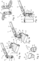
- the fitting arrangements 11 are each intended for use on the sash of a window, a door or the like (not shown) and each comprise a pivot arm 13 which is designed as a scissor arm and has a support bracket 15 at its hinge-side end.
- the support bracket 15 is designed as an angle with a leg 17 and a further leg 19, wherein the further leg 19 rests on the pivot arm 13 aligned parallel to the longitudinal extension of the pivot arm 13 and is firmly connected to it, while the leg 17 is aligned at an angle transverse to the longitudinal extension.
- the fitting arrangements 11 also each comprise a bearing band 21, which is designed as a band angle.
- the bearing band 21 has a substantially sleeve-shaped bearing section 23, into which a bearing pin of a frame-side pivot bearing (not shown) can engage in order to mount the bearing band 21 and, via the carrying bracket 15, ultimately the entire pivot arm 13 on the pivot bearing so that it can pivot about a rotation axis of the pivot bearing.
- the bearing band 21 also has a plate-shaped coupling section 25, which is angled relative to the bearing section 23 in such a way that it is offset parallel to an alignment radial to the rotation axis.
- a bayonet lock 27 which comprises a bayonet bolt 29 formed on the coupling section 25 of the bearing strip 21 and a bayonet receptacle 31 formed in the leg 17 of the carrying handle 15.
- the bayonet bolt 29 extends along a bolt axis B, to which it is rotationally symmetrical (see in particular Fig.2 ).
- Fig.1 , 4 , 6 , 9 and 12 illustrate, to close the bayonet lock 27, the bayonet bolt 29 is inserted axially, ie parallel to the bolt axis B, into the bayonet receptacle 31 and then rotated relative to the bolt receptacle 31 about the bolt axis B into the Fig. 1c , 4c , 6c , 9c and 12c shown coupling position.
- the form-locking means 33 of the bayonet bolt 29 engage behind corresponding form-locking means 35 of the bayonet receptacle 31, whereby the bayonet bolt 29 is secured in a form-locking manner against axially escaping from the bayonet receptacle 31.
- the form-locking means 33 of the bayonet bolt 29 are designed as two bayonet wings, which are connected by two radially outwardly projecting projections diametrically opposite to one another with respect to the bolt axis B. projections are formed.
- the corresponding form-locking means 35 of the bayonet receptacle 31 are formed by two undercuts which are arranged diametrically opposite one another in a manner similar to the bayonet wings of the bayonet bolt 29 and are thus each engaged by one of the bayonet wings when the bayonet bolt 29 is in its coupling position.
- the bayonet wings can be guided past the undercuts so that the bayonet bolt 29 can be inserted axially into the bayonet receptacle 31 or can be removed axially from the bayonet receptacle 31 to release the coupling.
- the bayonet bolt 29 of the first embodiment is shown separately in two representations from different angles.
- the fifth embodiment shown are each, particularly with regard to the design of the form-locking means 33, at least substantially identical to the one shown in Fig. 2 shown bayonet bolt 29.
- the bayonet bolt 29 has a base section 45, the cross section of which has a circular shape with two flattened areas arranged diametrically opposite one another.
- the bayonet bolt 29 can be inserted into a rivet hole 47 (cf. Fig.7 and 10 , in which the bearing band 21 of the third and fourth embodiments is shown without the bayonet bolt 29), which is formed in the coupling section 25 of the bearing band 21 and has a corresponding cross section, is inserted and then firmly connected to the bearing strip 21 (see also Fig. 13 ).
- the rigid arrangement of the bayonet bolt 29 according to the invention results in particular from the described cross-sectional shape of the base section 45 and the rivet hole 47, due to which the bayonet bolt 29 is positively locked against rotation relative to the bearing strip 21.
- the bayonet bolt 29 is arranged rigidly, in particular rotationally fixed, on the coupling section 25 of the bearing band 21, the entire bearing band 21 must be rotated relative to the carrying handle 15 in order to rotate the bayonet bolt 29 in the bayonet receptacle 31.
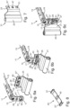
- the movement sequence required for closing the bayonet lock 27 is determined for the various embodiments by the Fig. 1a-1c , 4a-4c, 6a-6c , 9a-9c or 12a-12c clarified.
- the bearing strip 21 In order for the bayonet bolt 29 of the bearing strip 21 to be inserted into the bayonet receptacle 31 of the carrying handle 15, the bearing strip 21 must first be rotated by 90° relative to the carrying handle 15 in comparison to the orientation in which these components are ultimately to be coupled together and then takes the Fig. 1a , 4a , 6a , 9a or 12a, which corresponds to a release position of the bayonet bolt 29 relative to the bayonet receptacle 31. In Fig. 1b , 4b , 6b , 9b or 12b, the bayonet bolt 29 is already axially inserted into the bayonet receptacle 31, but is still in the release position so that the bayonet lock 27 is not yet closed.
- the intermediate state in which the bayonet bolt 29 is already axially inserted into the bayonet receptacle 31, but is not yet (completely) rotated into the coupling position (cf. Fig. 1b , 4b , 6b , 9b or 12b), can be clearly distinguished from an actually closed state of the bayonet catch 27 based on the alignment of the bearing band 21 relative to the carrying handle 15. This reliably excludes the possibility of the bayonet catch 27 being considered closed even though the bayonet bolt 29 is not yet in the coupling position.
- no tools are advantageously required for the described turning, since the bearing band 21 and the carrying handle 15 (or the entire swivel arm 13) can simply be grasped by hand and rotated against each other.
- the bearing band 21 can be moved not only into the intermediate position shown in the five embodiments shown Fig. 1c , 4c , 6c , 9c or 12c, but can also be rotated in the opposite direction of rotation by 90° into an alternative position that corresponds to a further coupling position of the bayonet bolt 29 in the bayonet receptacle 31.
- the two bayonet wings of the bayonet bolt 29 engage behind the one of the two undercuts of the bayonet receptacle 31 that they do not engage behind in the coupling position shown.
- the form-fitting effect in the alternative coupling position is the same as in the coupling position shown.
- the bearing section 23 in the alternative Position compared to the position shown with respect to the bolt axis B is arranged exactly diametrically opposite.
- the fitting arrangement 11 can be configured for a left-opening or a right-opening sash depending on which of the two positions the bearing band 21 is rotated into. This is also helped by the fact that the bearing band 21 is designed to be mirror-symmetrical to a mirror plane containing the bolt axis B.
- anti-twisting means are provided between the coupling section 25 of the bearing band 21 and the angled leg 17 of the carrying handle 15, which prevent rotation of the bearing band 21 relative to the carrying handle 15 when the bayonet lock 27 is closed.
- the various embodiments differ in particular with regard to the respective design of these anti-twisting means.
- the carrying handle 15 has on its leg 17 a locking projection 37 which projects parallel to the bolt axis B (cf. Fig.3 ), while the coupling section 25 of the bearing band 21 has two locking recesses 39, 39', which each correspond to the locking projection 37, i.e. are designed to be at least substantially complementary for interaction.
- the locking recesses 39, 39' are arranged such that the locking projection 37 of the carrying bracket 15 engages in one locking recess 39 when the bearing band 21 is coupled to the carrying bracket 15 and aligned such that the bayonet bolt 29 assumes its coupling position, and engages in the other locking recess 39' when the bearing band 21 is coupled to the carrying bracket 15 and aligned such that the bayonet bolt 29 assumes its further coupling position.
- the locking projection 37 is formed integrally with the day bracket 15 by embossing (cf. Fig.3 , in which the carrying handle 15 of the first embodiment is shown separately).
- the locking recesses 39, 39' are designed as holes in the Coupling section 25 of the bearing band 21 is formed.
- the cross sections of the locking projection 37 and the locking recesses 39, 39' are each circular.
- run-on bevels 41, 41' are formed on two corresponding edge sections of the coupling section 25.
- the run-on bevels 41, 41' are arranged in such a way that the locking projection 37 runs against one run-on bevel 41 when the bayonet bolt 29 is rotated into the coupling position, or against the other run-on bevel 41' when the bayonet bolt 29 is rotated into the further coupling position, thereby being axially pushed back in relation to the bolt axis B and thus sliding onto the coupling section 25.
- the leg 17 of the carrying bracket 15 and the coupling section 25 of the bearing band 21 are clamped against each other so that the locking projection 37 is pressed against the coupling section 25 until it automatically locks into the locking recess 39 or 39' when the coupling position or the further coupling position is reached.
- the second embodiment shown differs from the first embodiment essentially in that on the leg 17 of the carrying handle 15 there is no locking projection, but rather a locking recess 39 of the type described above, and instead on the coupling section 25 of the bearing band 21 there are no locking recesses, but rather locking projections 37, 37' of the type described above, each integrally formed. Since the carrying handle 15 has no locking projection (cf. Fig.5 , in which the carrying handle 15 of the second embodiment is shown separately), no run-on bevel needs to be formed on the coupling section 25. Instead, beveled lateral edges of the leg 17 of the carrying handle 15 can be used as run-on bevels 41, 41' (cf. Fig.5 ) act in a corresponding manner as described above in order to axially push back a respective one of the locking projections 37, 37' depending on the direction of rotation so that it can slide onto the leg 17 and finally engage in the locking recess 39.
- two locking projections 37, 37' are also provided, both of which are part of an elastic spring device 43 designed as a leaf spring.
- This spring device 43 which in Fig.8 is shown separately, has two end sections which are bent over compared to the otherwise flat spring device 43.
- the locking projections 37, 37' are formed by these bent over end sections and thus protrude from the rest of the spring device 43.
- To attach the spring device 43 it has a rivet hole 47 of the bearing strip 21 (cf. Fig.7 ) has a hole 49 corresponding in shape through which the bayonet bolt 29 extends with its base section 45.
- the spring device 43 therefore extends completely around the base section 45 of the bayonet bolt 29.
- the coupling section 25 of the bearing band 21 has, in addition to the rivet hole 47, two securing recesses 51, 51', which are provided in the area of the locking projections 37, 37' and are therefore aligned with the locking recess 39 in the coupling position or the further coupling position of the bayonet bolt 29 (with respect to a viewing direction parallel to the bolt axis B).
- These securing recesses 51, 51' enable the resilient locking projections 37, 37' to retreat axially in the direction away from the leg 17 of the carrying handle 15 when they run into the coupling position or the further coupling position against the leg 17 as a result of the rotation of the bearing band 21 and are thereby pushed back.
- the respective locking projection 37 or 37' can finally spring back into the locking recess 39.
- the end sections of the spring device 43 which form the locking projections 37, 37', are further bent back in such a way that the spring device 43 engages with the ends of its longitudinal extension in the securing recesses 51, 51' even in the relaxed state. This additionally secures the spring device 43 against twisting relative to the bearing strip 21.
- the spring device 43 also engages in the securing recesses 51, 51' in this way, so that the end section which forms the locking projection 37 or 37' engaging in the locking recess 39 simultaneously engages at least partially in the corresponding securing recess 51 or 51'. Due to the small distance between the locking recess 39 and the respective securing recess 51 or 51' and the simultaneous engagement of the same end section in both recesses, a particularly reliable locking against rotation of the bearing strip 21 relative to the carrying bracket 15 is achieved.
- the fourth embodiment shown differs from the third embodiment primarily in terms of the shape of the elastic spring device 43.
- the spring device 43 is also designed as a leaf spring, which, however, is laterally expanded compared to the third embodiment and therefore essentially covers the entire coupling section 25 of the bearing band 21.
- the end sections of the spring device 43, which form the locking projections 37, 37' are bent several times in a different way, namely in such a way that first a partial section is bent backwards, ie in the direction away from the carrying handle 15, in order to engage in the respective securing recess 51 or 51', and a partial section adjoining it radially outwards is bent forwards, ie in the direction towards the carrying handle 15. is bent to engage in the locking recess 39 when the bayonet lock 27 is closed.
- the securing recesses 51, 51' have a different design compared to the third embodiment.
- the securing recesses 51, 51' in the fourth embodiment are not closed circumferentially, but are perforated radially outwards with respect to the bolt axis B.
- the locking projections 37, 37' and the locking recess 39 can also extend radially further outwards or be arranged radially further outwards. Due to the greater distance from the bolt axis B, the anti-twisting device can withstand greater torques due to the engagement of the respective locking projection 37 or 37' in the locking recess 39 and can therefore be particularly secure.
- the elastic spring device 43 is not arranged on the bearing band 21, but on the leg 17 of the carrying handle 15.
- the carrying handle 15 is in Fig. 14 shown separately, with the spring device 43 shown twice in this figure, namely once on the carrying handle 15 and also once separately for better differentiation.
- the spring device 43 is designed as a leaf spring which is inserted into a spring receptacle 53 formed on the leg 17 of the carrying handle 15 and is braced therein.
- a bent end section of the spring device 43 which protrudes from the leg 17 in the direction of the coupling section 25 of the bearing band 21, forms the locking projection 37.
- the coupling section 25 of the bearing strip 21 has two locking recesses 39, 39' arranged diametrically opposite to each other with respect to the bolt axis B of the bayonet bolt 29.
- the locking recesses 39, 39' are not closed circumferentially, but perforated outwards in a radial direction with respect to the bolt axis B.
- the coupling section 25 has two starting contours 55, 55', each of which extends to one of the locking recesses 39, 39'.
- the starting contours 55, 55' are arranged in such a way that when the bearing strip 21 is inserted into the bayonet receptacle 31 with the bayonet bolt 29 and is rotated in the direction of the coupling position or the further coupling position, the locking projection 37 runs against one of the two starting contours 55, 55' and is thereby pushed back radially with respect to the bolt axis B.
- the Fig. 13 which shows an intermediate state of rotation of the bearing band 21 relative to the carrying bracket 15, in which the locking projection 37 is deflected radially by the starting contour 55.
- the locking projection 37 experiences a restoring force which prestresses it radially inwards so that it finally locks into the locking recess 39 shortly before or when the coupling position is reached.
- the locking projection 37 penetrates into the respective locking recess 39 or 39' in a radial direction. Subsequently, in the coupling position or the further coupling position (as in the other embodiments), the locking projection 37 then axially engages in the respective locking recess 39 or 39', which positively locks the bearing band 21 against rotation about the bolt axis B relative to the carrying handle 15. In this way, the fitting arrangement 11 is particularly reliably secured against the bayonet lock 27 coming loose automatically.
Landscapes
- Engineering & Computer Science (AREA)
- Mechanical Engineering (AREA)
- Pivots And Pivotal Connections (AREA)
- Hinges (AREA)
- Snaps, Bayonet Connections, Set Pins, And Snap Rings (AREA)
Description
- Die Erfindung betrifft eine Beschlaganordnung für den Flügel eines Fensters, einer Tür oder dergleichen, insbesondere für einen Flügel, der dreh-kipp-öffenbar ist.
- Eine solche Beschlaganordnung kann den Flügel beweglich an einem Rahmen des Fensters oder der Tür lagern. Dazu wird die Beschlaganordnung am Flügel befestigt und werden auf der sogenannten Bandseite des Fensters oder der Tür entsprechende Gegenstücke am Rahmen befestigt, an denen die Beschlaganordnung dann mittels eines Lagerbandes beweglich, insbesondere schwenkbar, gelagert werden kann. Die Beschlaganordnung kann beispielsweise einen länglichen Schwenkarm umfassen, der an dem Flügel befestigt wird und an seinem bandseitigen Ende über das Lagerband mit einem am Rahmen vorzusehenden Schwenklager verbunden wird, beispielsweise indem das Lagerband an dem Schwenklager eingehängt wird, so dass der Schwenkarm und mit ihm der Flügel durch das Schwenklager gehalten werden, aber zugleich bewegt, insbesondere um eine durch das Schwenklager definierte Drehachse geschwenkt, werden können. Als Lagerband kommt insbesondere ein sogenannter Bandwinkel in Betracht, der ein- oder mehrfach abgewinkelt sein kann, um einen gewissen Versatz zwischen dem Schwenkarm und dem Schwenklagern zu erzielen.
- Je nach Form, Gewicht und gewünschter Funktion, insbesondere je nach Art der Öffenbarkeit, des Flügels können dabei sehr unterschiedliche Beschlaganordnungen zum Einsatz kommen. Typischerweise wird für einen Flügel, der sowohl drehals auch kipp-öffenbar sein soll, als Schwenkarm ein sogenannter Scherenarm genutzt, der es derjenigen Seite des Flügels, an der er vorgesehen ist, ermöglicht, gegenüber einer ausschließlich radial zum jeweiligen Lager ausgerichteten Lage parallel ausgestellt zu werden, so dass der Flügel dadurch um seine entgegengesetzte Seite gekippt wird. Der genannte Schwenkarm kann aber grundsätzlich auch als reiner Drehbandarm oder reiner Kippbandarm (bzw. Dreh- oder Kippbandstulp) ausgebildet sein oder eine sonstige Kinematik des Flügels gegenüber dem Rahmen ermöglichen.
- Eine entsprechende Variabilität wie bei den Schwenkarmen ist bei den Schwenklagern, insbesondere bei den sogenannten Scherenlagern, die an der jeweiligen Bandseite des Flügels typischerweise oben vorgesehen werden, nicht erforderlich. Denn sie müssen in der Regel lediglich die Schwenkbarkeit des jeweiligen Schwenkarms ermöglichen und sind somit im Wesentlichen unabhängig von der Form des Flügels und von der Art seiner Öffenbarkeit. Das Lagerband, über das ein Schwenkarm an einem Schwenklager gelagert wird, kann daher für verschiedene Schwenkarme jeweils gleichartig ausgebildet sein. Aus diesem Grund ist es zweckmäßig, die Lagerbänder nicht als integraler Bestandteil der Schwenkarme, sondern als separate Teile zu fertigen, die dann jeweils mit einem Schwenkarm fest verbunden werden. Auf diese Weise können unterschiedliche Schwenkarme herstellt werden, die aber jeweils dasselbe Lagerband aufweisen.
- Ein weiterer Vorteil einer zweiteiligen Ausbildung besteht zudem darin, dass ein jeweiliger Schwenkarm auf diese Weise nicht von vornherein darauf festgelegt ist, wo die Bandseite des Flügels ist, also um welche seiner Seiten der Flügel schwenkbar ist. Insbesondere kann ein jeweiliger Schwenkarm für sich grundsätzlich sowohl an links- als auch an rechtsöffnenden Flügeln verwendbar sein. Erst durch die Kopplung mit einem Lagerband wird der Schwenkarm dann auf eine bestimmte Bandseite festgelegt. Diese Festlegung kann sich dabei durch die Wahl des Lagerbandes und/oder durch die Art der Anordnung des Lagerbandes an dem Schwenkarm ergeben. In letztgenanntem Fall kann die Beschlaganordnung somit durch Änderung der Ausrichtung des Lagerbandes an dem Schwenkarm auch umkonfigurierbar sein. Dadurch kann die Beschlaganordnung besonders flexibel einsetzbar sein.
- Bei einer separaten Ausbildung des Schwenkarms und des Lagerbandes ist es jedoch wichtig, dass diese Teile spätestens bei der Montage der Beschlaganordnung an einem jeweiligen Flügel zuverlässig miteinander gekoppelt werden. Denn insbesondere in aufgeschwenktem Zustand wird der Flügel zu einem wesentlichen Anteil über diese Kopplung von dem Rahmen getragen.
- Der Schwenkarm erstreckt sich typischerweise radial zur Drehachse und ist daher an einer der senkrecht zur Bandseite ausgerichteten Seiten des Flügels an diesem befestigt. Das Lagerband dagegen ist für das Zusammenwirken mit dem Schwenklager in der Regel an der Bandseite des Flügels angeordnet. Daher ist es zweckmäßig, wenn der Schwenkarm an seinem bandseitigen Ende einen Tragebügel aufweist, der einen gegenüber dem übrigen Schwenkarm abgewinkelten Schenkel umfasst, welcher zur Kopplung mit dem Lagerband genutzt werden kann.
- Beispielsweise kann das Lagerband mit dem abgewinkelten Schenkel des Tragebügels einfach verschraubt oder vernietet werden. Eine solche Art der Kopplung setzt jedoch die Verwendung von Werkzeug voraus und bedeutet somit zusätzlichen Aufwand bei der Montage der Beschlaganordnung. Eine Nietverbindung ist zudem irreversibel, so dass die Beschlaganordnung nicht mehr umkonfiguriert werden kann, falls der falsche Schwenkarm ausgewählt wurde oder die falsche Bandseite eingestellt wurde.
- Eine einfach zu schließende, dabei aber zuverlässige und zudem wieder lösbare Art der Verbindung kann mittels eines Bajonettverschlusses ermöglicht werden. Dazu kann insbesondere vorgesehen sein, dass an dem Tragebügel des Schwenkarms eine Bajonettaufnahme und an einem Kopplungsabschnitt des Lagerbandes ein drehbarer Bajonettbolzen vorgesehen wird. So können der Tragebügel und das Lagerband ineinandergesteckt und durch Drehen des Bajonettbolzens in der Bajonettaufnahme aneinander befestigt werden.
- Nachteilig an einer solchen Art der Verbindung kann aber sein, dass zum Drehen des typischerweise schlecht greifbaren Bajonettbolzens wiederum Werkzeug erforderlich sein kann. Zudem besteht die Gefahr, dass sich der drehbare Bajonettbolzen mit der Zeit, etwa aufgrund der Betätigung des Flügels oder durch auftretende Erschütterungen, zurückdreht und sich die Verbindung dadurch löst.
- Schließlich besteht auch die Gefahr, dass bei der Montage der Beschlaganordnung das Drehen des in die Bajonettaufnahme eingesteckten Bajonettbolzens zum Verriegeln des Bajonettverschlusses einfach vergessen wird, da der Schwenkarm und das Lagerband bereits durch das bloße Einstecken verbunden erscheinen, obwohl sie noch gar nicht formschlüssig aneinander gesichert sind.
DE3024746A1 offenbart ein Beispiel einer Beschlaganordnung. - Es ist eine Aufgabe der Erfindung, eine Beschlaganordnung der eingangs genannten Art bereitzustellen, die flexibel einsetzbar ist, sich besonders einfach und sicher montieren lässt und zugleich eine zuverlässige Kopplung des Lagerbandes am Schwenkarm gewährleistet.
- Die Aufgabe wird gelöst durch eine Beschlaganordnung mit den Merkmalen des Anspruchs 1. Vorteilhafte Ausführungsformen der Erfindung ergeben sich aus den Unteransprüchen, der vorliegenden Beschreibung sowie den Figuren.
- Die erfindungsgemäße Beschlaganordnung für den Flügel eines Fensters, einer Tür oder dergleichen umfasst einen Schwenkarm, der dazu ausgebildet ist, an dem Flügel befestigt zu werden, und der an einem bandseitigen Ende seiner Längserstreckung einen Tragebügel mit einem quer zu der Längserstreckung abgewinkelten Schenkel aufweist. Bei dem Flügel kann es sich insbesondere um einen dreh-kipp-öffenbaren Flügel handeln. Der Schwenkarm kann hierfür insbesondere als Scherenarm ausgebildet sein. Der Schwenkarm weist insbesondere eine längliche Form auf, die sich zwischen dem genannten bandseitigen Ende und einem dazu entgegengesetzten bandfernen Ende erstreckt. Die beiden Enden definieren eine Längsachse des Schwenkarms, entlang welcher die genannte Längserstreckung definiert ist.
- Der Tragebügel mit dem gegenüber der sonstigen Längserstreckung des Schwenkarms abgewinkelten Schenkel kann grundsätzlich mit dem Schwenkarm als bauliche Einheit ausgebildet sein. Beispielsweise kann der Tragebügel einem Abschnitt des Schwenkarms entsprechen und im Wesentlichen dadurch gebildet sein, dass der Schwenkarm an seinem bandseitigen Ende umgebogen ist, so dass der umgebogene Teil den genannten Schenkel bildet. Vorzugsweise ist der Tragebügel jedoch ein von dem Schwenkarm separat gefertigtes Bauteil, das fest mit dem Schwenkarm verbunden, z.B. vernietet, ist. Dabei kann der Tragebügel im Wesentlichen als ein Winkel mit zwei Schenkeln ausgebildet sein, von denen einer den genannten abgewinkelten Schenkel bildet. Der weitere Schenkel des Tragebügels dient dann der Befestigung des Tragebügels an dem Schwenkarm und ist zweckmäßigerweise parallel zur Längserstreckung des Schwenkarms ausgerichtet.
- Der Schwenkarm ist vorzugsweise dazu ausgebildet, im Falz an einer Seite des Flügels, insbesondere an dessen Oberseite, befestigt zu werden. Der Tragebügel kann dabei dann an einer Ecke des Flügels angeordnet werden und diese umgreifen, insbesondere derart, dass der genannte abgewinkelte Schenkel zumindest im Wesentlichen vertikal ausgerichtet ist.
- Die Beschlaganordnung umfasst ferner ein Lagerband, das dazu ausgebildet ist, mit einem Lagerabschnitt an einem am Rahmen des Fensters oder der Tür vorzusehenden Schwenklager um eine Drehachse des Schwenklagers schwenkbar gelagert zu werden, und das einen Kopplungsabschnitt aufweist, der mittels eines Bajonettverschlusses mit dem abgewinkelten Schenkel des Tragebügels des Schwenkarms koppelbar ist.
- Der genannte Lagerabschnitt kann beispielsweise als Hülse ausgebildet sein, in die ein Lagerstift des rahmenseitigen Schwenklagers eingreifen kann, so dass das Lagerband um den Lagerstift drehbar ist. Der genannte Kopplungsabschnitt des Lagerbandes kann beispielsweise zumindest im Wesentlichen eine Plattenform aufweisen. Das Lagerband kann insbesondere als sogenannter Bandwinkel ausgebildet sein. Dabei kann das Lagerband derart (auch mehrfach) abgewinkelt sein, dass die durch die Plattenform des Kopplungsabschnitts definierte Ebene von einer zur Drehachse radialen Ausrichtung abweicht, beispielsweise um einen Winkel von zumindest 30° und/oder höchstens 60°, insbesondere etwa 45°. Bei dem Schwenklager kann es sich insbesondere um ein sogenanntes Scherenlager handeln.
- Der Bajonettverschluss umfasst einen sich entlang einer Bolzenachse erstreckenden Bajonettbolzen sowie eine Bajonettaufnahme, die derart ausgebildet sind, dass zum Schließen des Bajonettverschlusses der Bajonettbolzen bezüglich der Bolzenachse axial in die Bajonettaufnahme eingesteckt und anschließend relativ zu der Bajonettaufnahme um die Bolzenachse in eine Kopplungsstellung gedreht wird, in der Formschlussmittel des Bajonettbolzens korrespondierende Formschlussmittel der Bajonettaufnahme hintergreifen und den Bajonettbolzen dadurch gegen ein (bezüglich der Bolzenachse) axiales Austreten aus der Bajonettaufnahme sperren. Dabei kann insbesondere vorgesehen sein, dass das genannte Einstrecken eine reine Translationsbewegung ist, also durch keine Drehung überlagert wird. Das anschließende Drehen in die Kopplungsstellung dagegen kann auch durch Bewegungsanteile in axialer Richtung überlagert sein, beispielsweise nach Art einer Schraubbewegung und/oder für das Überwinden einer Rastkante. Grundsätzlich kann es sich aber auch um eine reine Drehung ohne Bewegungsanteile in axialer Richtung handeln.
- Nachdem der Bajonettbolzen in die Bajonettaufnahme eingesteckt ist, aber bevor er anschließend relativ zu der Bajonettaufnahme gedreht wird, befindet sich der Bajonettbolzen dabei in einer Freigabestellung, in der die Formschlussmittel des Bajonettbolzens die korrespondierenden Formschlussmittel der Bajonettaufnahme nicht hintergreifen und der Bajonettbolzen daher wieder axial aus der Bajonettaufnahme austreten kann. Durch Zurückdrehen des Bajonettbolzens aus der Kopplungsstellung in die Freigabestellung kann der Formschluss daher auch wieder aufgehoben und der Bajonettverschluss somit wieder gelöst werden.
- Mit anderen Worten sind der Bajonettbolzen und die Bajonettaufnahme insbesondere derart ausgebildet, dass zum Schließen des Bajonettverschlusses der Bajonettbolzen bezüglich der Bolzenachse axial in die Bajonettaufnahme eingesteckt und anschließend relativ zu der Bajonettaufnahme um die Bolzenachse aus einer Freigabestellung in eine Kopplungsstellung gedreht wird, wobei in der Kopplungsstellung Formschlussmittel des Bajonettbolzens korrespondierende Formschlussmittel der Bajonettaufnahme hintergreifen und den Bajonettbolzen dadurch gegen ein axiales Austreten aus der Bajonettaufnahme sperren, in der Freigabestellung dagegen nicht; somit können der Bajonettbolzen und die Bajonettaufnahme vorteilhafterweise zudem derart ausgebildet sein, dass zum Öffnen des Bajonettverschlusses der Bajonettbolzen relativ zu der Bajonettaufnahme um die Bolzenachse aus der Kopplungsstellung in die Freigabestellung gedreht und anschließend bezüglich der Bolzenachse axial aus der Bajonettaufnahme entnommen wird.
- Vorzugsweise ist der Bajonettbolzen an dem Lagerband angeordnet, wobei die Bajonettaufnahme dann an dem Tragebügel vorgesehen ist. Grundsätzlich kann aber auch gerade umgekehrt der Bajonettbolzen an dem Tragebügel angeordnet sein; in diesem Fall ist die Bajonettaufnahme dann am Lagerband vorgesehen. Die Formschlussmittel können jeweils insbesondere durch bezüglich der Bolzenachse radiale Vorsprünge, beispielsweise Bajonettflügel, und/oder radiale Vertiefungen, beispielsweise Hinterschneidungen, Nuten oder Kulissenführungen, gebildet werden. Insbesondere kann der Bajonettbolzen einen oder mehrere derartige Vorsprünge, vorzugsweise zumindest zwei Bajonettflügel, aufweisen und die Bajonettaufnahme eine oder mehrere derartige Vertiefungen, vorzugsweise zumindest zwei Hinterschneidungen, aufweisen. Grundsätzlich kann aber auch die Bajonettaufnahme ein oder mehrere radiale Vorsprünge aufweisen und/oder der Bajonettbolzen ein oder mehrere radiale Vertiefungen aufweisen.
- Erfindungsgemäß ist der Bajonettbolzen an dem Tragebügel oder an dem Lagerband starr, insbesondere drehfest, angeordnet.
- Der Bajonettbolzen ist dabei insbesondere insofern an dem jeweiligen Element, an dem er vorgesehen ist, (Tragebügel bzw. Lagerband), starr angeordnet, als er relativ zu diesem Element nicht drehbar, vorzugsweis überhaupt nicht bewegbar, ist. Das hat zur Folge, dass der Bajonettbolzen für die beschriebene Steck-DrehBewegung zum Schließen der Bajonettverbindung nicht separat gedreht werden kann, sondern dass das gesamte Element, an dem er vorgesehen ist, mitgedreht werden muss. Insbesondere muss zum Schließen der Bajonettverbindung das gesamte Lagerband gegenüber dem Tragebügel oder auch gegenüber dem gesamten Scherenarm um die Bolzenachse gedreht werden. Da zum Öffnen des Bajonettverschlusses gerade der umgekehrte Bewegungsablauf (erst Drehen, dann axiales Herausführen des Bajonettbolzens aus der Bajonettaufnahme) ausgeführt werden muss, gilt entsprechendes auch für das Öffnen des Bajonettverschlusses.
- Der Bajonettbolzen kann grundsätzlich einteilig mit dem Tragebügel oder dem Lagerband ausgebildet sein. Einfacher kann der Bajonettbolzen jedoch als separates Bauteil gefertigt werden, das dann mit dem Tragebügel oder dem Lagerband derart fest, insbesondere drehfest, verbunden wird, dass er in dem beschriebenen Sinne starr daran angeordnet ist.
- Die Befestigung des Bajonettbolzens kann beispielsweise durch Vernieten erfolgen. Vorzugsweise ist der Bajonettbolzen an dem Tragebügel oder dem Lagerband vertaumelt. Die Befestigung ist dabei derart, dass der Bajonettbolzen relativ zu dem Tragebügel bzw. dem Lagerband zumindest reibschlüssig gegen ein Drehen gesichert ist. Bevorzugt ist der Bajonettbolzen alternativ oder zusätzlich formschlüssig gegen ein Drehen relativ zu dem Tragebügel bzw. dem Lagerband gesichert. Dazu können beispielsweise der Querschnitt eines Sockelabschnitts des Bajonettbolzens und der Querschnitt eines Nietlochs im Tragebügel oder im Lagerband, durch welches sich der Sockelabschnitt erstreckt, im Wesentlichen einander entsprechende Konturen aufweisen, wobei die Konturen jeweils von einer Kreisform abweichen, so dass der Sockelabschnitt in dem Nietloch formschlüssig gegen ein Drehen um die Bolzenachse gesperrt ist. Für eine noch zuverlässigere starre Verbindung kann die Befestigung grundsätzlich auch zumindest teilweise stoffschlüssig sein.
- Die für das Schließen oder Öffnen des Bajonettverschlusses erforderliche Drehung erstreckt sich vorteilhafterweise über einen Winkel von mindestens 60°, vorzugsweise von zumindest im Wesentlichen 90°. Dabei ist der Bajonettverschluss zweckmäßigerweise gerade derart ausgerichtet, dass, wenn der Bajonettbolzen in der Bajonettaufnahme seine Kopplungsstellung einnimmt, der Schwenkarm und das Lagerband ihre normale Funktionsstellung einnehmen, also derart relativ zueinander ausgerichtet sind, dass sie an einem Flügel befestigt werden können und dort ihre Funktion der schwenkbaren Lagerung des Flügels erfüllen können. Das bedeutet aber auch, dass der Schwenkarm und das Lagerband nur in einer um den genannten Drehwinkel von der Funktionsstellung verschiedenen Drehstellung ineinandergesteckt bzw. voneinander gelöst werden können. Das hat den Vorteil, dass dadurch zuverlässig ausgeschlossen wird, dass die Drehbewegung zum vollständigen Schließen der Bajonettverbindung vergessen wird. Denn solange der Bajonettbolzen nur in die Bajonettaufnahme eingesteckt wurde, nicht aber nach dem Einstecken auch in die Kopplungsstellung gedreht wurde, nehmen der Schwenkarm und das Lagerband nicht ihre normale Funktionsstellung ein, sondern sind relativ zueinander verdreht. Dies fällt dann deutlich auf; insbesondere kann die Beschlaganordnung in diesem Zustand unter Umständen gar nicht am Flügel montierbar sein.
- Ein weiterer Vorteil eines starren Bajonettbolzens besteht darin, dass zum Drehen des Bajonettbolzens kein Werkzeug erforderlich ist. Denn für das Drehen muss nicht der Bajonettbolzen selbst gegriffen werden, sondern es kann das Element gegriffen werden, an dem der Bajonettbolzen vorgesehen ist, also das Lagerband oder der Tragebügel bzw. der Scherenarm als Ganzes. Da sowohl das Lagerband als auch der Scherenarm wesentlich größer ausgebildet sind als der Bajonettbolzen, lassen sie sich leichter und in der Regel ohne Werkzeug greifen; zudem kann dadurch auf einfachere Weise ein hinreichendes Drehmoment für die den Bajonettverschluss schließende bzw. öffnende Drehbewegung erzeugt werden.
- Gemäß einer vorteilhaften Ausführungsform sind der Bajonettbolzen und die Bajonettaufnahme derart ausgebildet, dass der Bajonettbolzen nach dem genannten axialen Einsetzen in die Bajonettaufnahme wahlweise entweder in die genannte Kopplungsstellung oder in entgegengesetzter Drehrichtung um die Bolzenachse in eine weitere Kopplungsstellung gedreht werden kann, in der ebenfalls Formschlussmittel des Bajonettbolzens korrespondierende Formschlussmittel der Bajonettaufnahme hintergreifen und den Bajonettbolzen dadurch gegen ein axiales Austreten aus der Bajonettaufnahme sperren. Vorzugsweise ist der Bajonettbolzen in der weiteren Kopplungsstellung im Vergleich zu der Kopplungsstellung dabei um 180° gedreht. Auf diese Weise kann das Lagerband vorteilhafterweise mittels desselben Bajonettverschlusses in zwei unterschiedlichen Ausrichtungen, die vorzugsweise gerade entgegengesetzt zueinander sind, mit dem Tragebügel (und somit mit dem Schwenkarm) gekoppelt werden. Die zwei Ausrichtungen können dabei insbesondere gerade zwei unterschiedlichen Montagekonfigurationen der Beschlaganordnung entsprechen, wobei die eine Konfiguration beispielsweise für einen linksöffnenden Flügel und die andere für einen rechtöffnenden Flügel geeignet sein kann.
- Insbesondere in diesem Zusammenhang kann es ferner vorteilhaft sein, wenn das Lagerband zu einer Spiegelebene, welche zu der genannten Drehachse orthogonal ist und/oder die Bolzenachse enthält, spiegelsymmetrisch ausgebildet ist. Der Bezug zu der Drehachse des Schwenklagers ergibt durch die Art der Lagerung des Lagerbandes an dem Schwenklager und wird insbesondere durch die Ausbildung des Lagerabschnitts des Lagerbandes eindeutig definiert. Die spiegelsymmetrische Ausbildung des Lagerbandes ermöglicht es, dass die Beschlaganordnung zwei Konfigurationen aufweisen kann, die sich dadurch unterscheiden, dass das Lagerband in der einen Konfiguration um 180° gegenüber der Ausrichtung in der anderen verdreht ist, und das Lagerband trotz der unterschiedlichen Ausrichtung in beiden Konfigurationen auf im Wesentlichen identische Weise an dem Schwenklager gelagert werden kann.
- Gemäß einer weiteren vorteilhaften Ausführungsform sind zwischen dem Kopplungsabschnitt des Lagerbands und dem abgewinkelten Schenkel des Tragebügels Verdrehsicherungsmittel vorgesehen, die in der Kopplungsstellung des Bajonettbolzens, also bei geschlossenem Bajonettverschluss, automatisch wirksam werden und den Bajonettbolzen dann gegen ein Verlassen der Kopplungsstellung sichern. Durch derartige Verdrehsicherungsmittel wird somit auch der Bajonettverschluss als Ganzes gegen ein unbeabsichtigtes Öffnen gesichert. Sofern die oben genannte weitere Kopplungsstellung existiert, können auch Verdrehsicherungsmittel zum Sichern des Bajonettbolzens gegen ein Verlassen der weiteren Kopplungsstellung vorgesehen sein oder dieselben Verdrehsicherungsmittel zugleich auch diese Funktion erfüllen.
- Erfindungsgemäß weist der Tragebügel einen parallel zur Bolzenachse vorstehenden Rastvorsprung auf und weist das Lagerband eine korrespondierende Rastausnehmung auf; oder es ist gerade umgekehrt, so dass das Lagerband den Rastvorsprung aufweist und der Tragebügel die Rastausnehmung aufweist. Dabei sind dann jeweils der Rastvorsprung und die Rastausnehmung derart angeordnet, dass der Rastvorsprung in der Kopplungsstellung des Bajonettbolzens, also bei geschlossenem Bajonettverschluss, in die Rastausnehmung eingreift. Vorzugsweise greift der Rastvorsprung dabei bezüglich der Bolzenachse axial in die Rastausnehmung ein. Ferner erfolgt das Eingreifen bevorzugt zumindest im Wesentlichen mit Erreichen der Kopplungsstellung, beispielsweise indem der Rastvorsprung in die eingreifende Stellung vorgespannt ist und durch das Erreichen der Kopplungsstellung die Rastausnehmung gerade so platziert wird, dass das Eingreifen möglich wird. Das Eingreifen des Rastvorsprungs in die Rastausnehmung kann, vorteilhafterweise formschlüssig, verhindern, dass der Bajonettverschluss aus der Kopplungsstellung, insbesondere bis in die Freigabestellung, zurückgedreht werden kann. Insofern können der Rastvorsprung und die Rastausnehmung Verdrehsicherungsmittel im Sinne der vorstehend beschriebenen Ausführungsform darstellen.
- Grundsätzlich ist auch denkbar, dass sowohl der Tragebügel als auch das Lagerband jeweils zumindest einen parallel zur Bolzenachse vorstehenden Rastvorsprung sowie zumindest eine mit einem Rastvorsprung des jeweils anderen Bauteils korrespondierende Rastausnehmung aufweisen, wobei die Rastvorsprünge und Rastausnehmungen derart angeordnet sind, dass in der Kopplungsstellung des Bajonettbolzens, also bei geschlossenem Bajonettverschluss, der zumindest eine Rastvorsprung des Tragebügels in die zumindest eine Rastaufnahme des Lagerbandes und der zumindest eine Rastvorsprung des Lagerbandes in die zumindest eine Rastaufnahme des Tragebügels eingreift.
- Gemäß einer vorteilhaften Weiterbildung kann der Rastvorsprung in dem Tragebügel oder dem Lagerband, je nachdem, an welchem dieser beiden Elemente der Rastvorsprung vorgesehen ist, integral ausgebildet sein. Dabei kann diese integrale Ausbildung des Rastvorsprungs insbesondere durch Verformung, vorzugsweise durch Prägung, erzeugt sein. Auf diese Weise braucht für den Rastvorsprung kein gesondertes Bauteil vorgesehen zu werden. Insbesondere kann der Rastvorsprung zusammen mit dem Tragebügel bzw. dem Lagerband bei dessen Herstellung ausgebildet werden.
- Gemäß einer alternativen Weiterbildung kann vorgesehen sein, dass der Rastvorsprung Teil einer elastischen Federvorrichtung ist. Die Federvorrichtung ist dabei kein integraler Bestandteil des Tragebügels oder des Lagerbandes, sondern grundsätzlich separat davon ausgebildet, wobei sie aber mit dem Tragebügel oder dem Lagerband vorzugsweise fest verbunden ist. Der Rastvorsprung kann dabei als an der Federvorrichtung befestigte Struktur ausgebildet sein oder durch einen Abschnitt der Federvorrichtung selbst gebildet werden. Die Federvorrichtung kann insbesondere eine Blattfeder umfassen, an welcher der Rastvorsprung ausgebildet ist, oder insgesamt als derartige Blattfeder ausgebildet sein. Beispielsweise kann die Blattfeder eine federnd gelagerte Zunge aufweisen, an deren freiem Ende der Rastvorsprung ausgebildet ist. Der Rastvorsprung kann etwa durch einen ein- oder mehrfach umgebogenen Endabschnitt der Zunge gebildet werden, der infolge der Umbiegung zumindest teilweise parallel zur Bolzenachse von der übrigen Blattfeder und/oder dem Tragebügel bzw. dem Lagerband vorsteht.
- Wenn die Beschlaganordnung mehrere Rastvorsprünge zum Sichern des Bajonettverschlusses aufweist, können diese auch unterschiedlich ausgebildet sein. Beispielsweise kann zumindest einer der Rastvorsprünge auf die beschriebene Weise in dem Tragebügel oder dem Lagerband integral ausgebildet sein und zumindest ein anderer der Rastvorsprünge Teil einer, insbesondere als Blattfeder ausgebildeten, elastischen Federvorrichtung sein.
- Wenn zumindest ein Rastvorsprung als Teil einer elastischen Federvorrichtung ausgebildet ist, ist es gemäß einer vorteilhaften Weiterbildung ferner bevorzugt, wenn in der Kopplungsstellung des Bajonettbolzens die Rastausnehmung zumindest teilweise mit einer Sicherungsausnehmung fluchtet, die an dem Bauteil, an dem die Federvorrichtung vorgesehen ist, ausgebildet ist und in welche die Federvorrichtung eingreift, um dadurch gegen ein Verdrehen relativ zu dem Bauteil gesichert zu sein. Mit anderen Worten ist bei dieser Ausführungsform vorgesehen, dass entweder das Lagerband die Rastausnehmung aufweist und der Tragebügel eine Sicherungsausnehmung aufweist, in welche ein Teil der Federvorrichtung eingreift, um dadurch gegen ein Verdrehen relativ zu dem Tragebügel gesichert zu sein, oder - gerade umgekehrt - der Tragebügel die Rastausnehmung aufweist und das Lagerband eine Sicherungsausnehmung aufweist, in welche ein Teil der Federvorrichtung eingreift, um dadurch gegen ein Verdrehen relativ zu dem Lagerband gesichert zu sein; wobei (in beiden Fällen) die Sicherungsausnehmung in der Kopplungsstellung des Bajonettbolzens zumindest teilweise mit der Rastausnehmung fluchtet.
- Das Fluchten ist dabei insbesondere auf eine zur Bolzenachse parallele Richtung bezogen zu verstehen. Mit anderen Worten fluchtet die Sicherungsausnehmung dann zumindest teilweise mit der Rastausnehmung, wenn bei Blick in eine zu der Bolzenachse parallele Blickrichtung die Sicherungsausnehmung und die Rastausnehmung einander zumindest teilweise überlappen. In axialer Richtung, d.h. parallel zur Bolzenachse, weisen die Sicherungsausnehmung und die Rastausnehmung dabei vorzugsweise einen geringen Abstand auf. Insbesondere grenzen die Sicherungsausnehmung und die Rastausnehmung in der Kopplungsstellung des Bajonettbolzens zumindest im Wesentlichen unmittelbar aneinander an oder sind nur durch die Federvorrichtung voneinander beabstandet.
- Da in der Kopplungsstellung der als Teil der Federvorrichtung ausgebildete Rastvorsprung in die Rastausnehmung des einen der zwei Bauteile (Lagerband und Tragebügel) eingreift und ein Teil der Federvorrichtung zugleich in die Sicherungsausnehmung am jeweils anderen der zwei Bauteile eingreift, wobei diese Sicherungsausnehmung mit der Rastausnehmung fluchtet, ergibt sich eine relativ unmittelbare gegenseitige Sperrung des Lagerbandes und des Tragebügels gegen ein Verdrehen relativ zueinander. Aufgrund des vorzugsweise geringen Abstandes der Sicherungsausnehmung und der Rastausnehmung zueinander treten daher auch bei einem Versuch, das Lagerband relativ zu dem Tragebügel aus der Kopplungsstellung heraus zu verdrehen, keine besonders hohen Drehmomente an der in beide Ausnehmungen eingreifenden Federvorrichtung auf. Somit wird durch eine solche Ausführungsform der Bajonettverschluss besonders zuverlässig in seinem geschlossenen Zustand gesichert.
- Wenn zumindest ein Rastvorsprung als Teil einer elastischen Federvorrichtung ausgebildet ist, ist es ferner (zusätzlich zu oder auch völlig unabhängig von dem vorstehend beschriebenen Vorsehen einer Sicherungsausnehmung) vorteilhaft, wenn sich die Federvorrichtung um einen Sockelabschnitt des Bajonettbolzens, mit dem der Bajonettbolzen an dem Lagerband oder dem Tragebügel befestigt ist, vollständig herum erstreckt. Beispielsweise kann die Federvorrichtung, bei der es sich vorzugsweise um eine Blattfeder handelt, ein Loch aufweisen, durch welches sich der Sockelabschnitt des Bajonettbolzens hindurch erstreckt. Bei einer solchen Ausbildung braucht die Federvorrichtung nicht durch gesonderte Befestigungsmittel an dem Lagerband bzw. dem Tragebügel befestigt, z.B. vernietet, zu werden, sondern kann indirekt durch die Befestigung des Bajonettbolzens an dem Lagerband bzw. dem Tragebügel mitbefestigt werden. Insbesondere kann die Federvorrichtung dabei zwischen dem Bajonettbolzen und dem Lagerband bzw. dem Tragebügel eingeklemmt sein. Ferner kann der Bajonettbolzen über seinen Sockelabschnitt an dem Lagerband oder dem Tragebügel vernietet sein. Die Federvorrichtung kann dann durch das Vernieten des Bajonettbolzens an dem Lagerband bzw. dem Tragebügel mitvernietet sein.
- Gemäß einer ersten erfindungsgemäßen Variante ist an dem Lagerband oder an dem Tragebügel eine Anlaufschräge ausgebildet, die derart angeordnet ist, dass der Rastvorsprung beim Drehen des Bajonettbolzens in die Kopplungsstellung gegen die Anlaufschräge anläuft und dadurch bezüglich der Bolzenachse axial zurückgedrängt wird. Eine solche Anlaufschräge kann dazu beitragen zu verhindern, dass der parallel zur Bolzenachse vorstehende Rastvorsprung beim Drehen des Lagerbandes relativ zu dem Tragebügel in Umlaufrichtung gegen eine Kante anschlägt und dadurch das Weiterdrehen bis in die Kopplungsstellung blockiert. Denn durch die Anlaufschräge wird der Rastvorsprung axial, also parallel zur Bolzenachse, zurückgedrängt, so dass durch geeignete Anordnung der Anlaufschräge auch eine Stufe über eine Kante hinweg überwunden werden kann. Zugleich kann durch das Zurückdrängen in axialer Richtung eine dementsprechend axiale Rückstellkraft auf den Rastvorsprung wirken, die ursächlich dafür sein oder zumindest dazu beitragen kann, dass der Rastvorsprung, wenn die Kopplungsstellung erreicht ist, automatisch axial in die Rastausnehmung eingreift, insbesondere einrastet.
- Gemäß einer zweiten erfindungsgemäßen Variante ist die Rastausnehmung in bezüglich der Bolzenachse radialer Richtung durchbrochen ausgebildet, wobei an dem Lagerband oder an dem Tragebügel eine Anlaufkontur ausgebildet ist, die derart angeordnet ist, dass der Rastvorsprung beim Drehen des Bajonettbolzens in die Kopplungsstellung gegen die Anlaufkontur anläuft und dadurch bezüglich der Bolzenachse radial zurückgedrängt wird.
- Eine solche Anlaufkontur kann dabei grundsätzlich in ähnlicher Weise wie die vorstehend beschriebene Anlaufschräge wirken und ein Blockieren der Drehbewegung infolge eines Anschlagens des Rastvorsprungs an einer Kante verhindern.
- Ein wesentlicher Unterschied der Anlaufkontur im Vergleich zu der Anlaufschräge besteht aber darin, dass die Anlaufkontur den gegen sie anlaufenden Rastvorsprung bezüglich der Bolzenachse nicht axial, sondern radial zurückdrängt. Der Rastvorsprung wird dadurch also radial um eine Stufe herumgeführt, beispielsweise durch den Verlauf eines Randes des Lagerbandes bzw. des Tragebügels. Das radiale Zurückdrängen kann dabei vorteilhafterweise eine radial auf den Rastvorsprung wirkende Rückstellkraft zur Folge haben. Die radial durchbrochene Ausbildung der Rastausnehmung ermöglicht dabei, dass der radial zurückgedrängte und entlang der Anlaufkontur geführte Rastvorsprung, wenn die Kopplungsstellung erreicht ist, infolge der genannten Rückstellkraft radial in die Rastausnehmung eindringen kann, in die er dann aufgrund seines zur Bolzenachse parallelen Vorstehendes gleichwohl axial eingreift.
- Grundsätzlich unabhängig von den vorstehend beschriebenen Varianten der Erfindung und davon, auf welchem Weg der Rastvorsprung in die Rastausnehmung gelangt, ist es ferner bevorzugt, wenn die Rastausnehmung jedenfalls in Umfangsrichtung um die Bolzenachse, insbesondere in diejenige Umfangsrichtung, in die der Bajonettbolzen aus der Kopplungsstellung in die Freigabestellung gedreht werden kann, geschlossen ist, so dass der parallel zur Bolzenachse vorstehende und in die Rastausnehmung eingreifende Rastvorsprung die Rastausnehmung nicht in Umfangsrichtung verlassen kann, sondern zunächst, insbesondere manuell, in axialer und/oder radialer Richtung aus der Rastausnehmung bewegt werden muss. Auf diese Weise kann ein selbsttätiges Lösen des Bajonettverschlusses nahezu ausgeschlossen werden.
- Die Erfindung wird im Folgenden lediglich beispielhaft anhand der Figuren weiter erläutert.
- Fig. 1a-1c
- zeigen eine erste Ausführungsform einer erfindungsgemäßen Beschlaganordnung in drei verschiedenen Stellungen des Lagerbandes relativ zu dem Schwenkarm.
- Fig. 2
- zeigt den Bajonettbolzen der ersten Ausführungsform in zwei Ansichten aus unterschiedlicher Perspektive.
- Fig. 3
- zeigt den Tragebügel der ersten Ausführungsform in zwei Ansichten aus unterschiedlicher Perspektive.
- Fig. 4a-4c
- zeigen eine zweite Ausführungsform einer erfindungsgemäßen Beschlaganordnung in drei verschiedenen Stellungen des Lagerbandes relativ zu dem Schwenkarm.
- Fig. 5
- zeigt den Tragebügel der zweiten Ausführungsform in zwei Ansichten aus unterschiedlicher Perspektive.
- Fig. 6a-6c
- zeigen eine dritte Ausführungsform einer erfindungsgemäßen Beschlaganordnung in drei verschiedenen Stellungen des Lagerbandes relativ zu dem Schwenkarm.
- Fig. 7
- zeigt das Lagerband der dritten Ausführungsform.
- Fig. 8
- zeigt eine Federvorrichtung der dritten Ausführungsform.
- Fig. 9a-9c
- zeigen eine vierte Ausführungsform einer erfindungsgemäßen Beschlaganordnung in drei verschiedenen Stellungen des Lagerbandes relativ zu dem Schwenkarm.
- Fig. 10
- zeigt das Lagerband der vierten Ausführungsform.
- Fig. 11
- zeigt eine Federvorrichtung der vierten Ausführungsform.
- Fig. 12a-12c
- zeigen eine fünfte Ausführungsform einer erfindungsgemäßen Beschlaganordnung in drei verschiedenen Stellungen des Lagerbandes relativ zu dem Schwenkarm.
- Fig. 13
- zeigt einen Ausschnitt der Beschlaganordnung gemäß der fünften Ausführungsform in einer weiteren Stellung des Lagerbandes relativ zu dem Schwenkarm aus einem im Vergleich zu den
Fig. 12a-12c veränderten Blickwinkel. - Fig. 14
- zeigt den Tragebügel der fünften Ausführungsform mit einer Feder-vorrichtung, die einmal am Tragebügel angeordnet und zusätzlich einmal separat dargestellt ist.
- Die Figuren zeigen verschiedene Ausführungsformen erfindungsgemäßer Beschlaganordnungen 11 oder Teile von solchen. Dabei sind Bauteile verschiedener Ausführungsformen, die einander entsprechen, jeweils mit demselben Bezugszeichen gekennzeichnet.
- Die Beschlaganordnungen 11 sind jeweils zur Verwendung an dem Flügel eines Fensters, einer Tür oder dergleichen (nicht gezeigt) gedacht und umfassen jeweils einen Schwenkarm 13, der als Scherenarm ausgebildet ist und an seinem bandseitigen Ende einen Tragebügel 15 aufweist. Der Tragebügel 15 ist als ein Winkel mit einem Schenkel 17 und einem weiteren Schenkel 19 ausgebildet, wobei der weitere Schenkel 19 parallel zur Längserstreckung des Schwenkarms 13 ausgerichtet an dem Schwenkarm 13 anliegt und mit diesem fest verbunden ist, während der Schenkel 17 quer zur Längserstreckung abgewinkelt ausgerichtet ist.
- Die Beschlaganordnungen 11 umfassen ferner jeweils ein Lagerband 21, das als Bandwinkel ausgebildet ist. Das Lagerband 21 weist einen im Wesentlichen hülsenförmigen Lagerabschnitt 23 auf, in den ein Lagerstift eines nicht gezeigten rahmenseitigen Schwenklagers eingreifen kann, um das Lagerband 21 und über den Tragebügel 15 letztlich den gesamten Schwenkarm 13 um eine Drehachse des Schwenklagers schwenkbar an dem Schwenklager zu lagern. Das Lagerband 21 weist ferner einen plattenförmigen Kopplungsabschnitt 25 auf, der gegenüber dem Lagerabschnitt 23 derart abgewinkelt ist, dass er gegenüber einer zur Drehachse radialen Ausrichtung parallelversetzt ist.
- Über den abgewinkelten Schenkel 17 und den Kopplungsabschnitt 25 sind der Tragebügel 15 und das Lagerband 21 miteinander koppelbar. Dazu ist ein Bajonettverschluss 27 vorgesehen, der einen an dem Kopplungsabschnitt 25 des Lagerbandes 21 ausgebildeten Bajonettbolzen 29 sowie eine in dem Schenkel 17 des Tragebügels 15 ausgebildete Bajonettaufnahme 31 umfasst. Der Bajonettbolzen 29 erstreckt sich entlang einer Bolzenachse B, zu der er rotationssymmetrisch ausgebildet ist (vgl. insbesondere
Fig. 2 ). - Wie insbesondere die
Fig. 1 ,4 ,6 ,9 und12 veranschaulichen, wird zum Schließen des Bajonettverschlusses 27 jeweils der Bajonettbolzen 29 axial, d.h. parallel zu der Bolzenachse B, in die Bajonettaufnahme 31 eingesteckt und anschließend relativ zu der Bolzenaufnahme 31 um die Bolzenachse B in die in denFig. 1c ,4c ,6c ,9c und12c gezeigte Kopplungsstellung gedreht. - In der Kopplungsstellung hintergreifen Formschlussmittel 33 des Bajonettbolzens 29 korrespondierende Formschlussmittel 35 der Bajonettaufnahme 31, wodurch der Bajonettbolzen 29 gegen ein axiales Austreten aus der Bajonettaufnahme 31 formschlüssig gesichert ist. Die Formschlussmittel 33 des Bajonettbolzens 29 sind dabei als zwei Bajonettflügel ausgebildet, die durch zwei bezüglich der Bolzenachse B diametral entgegengesetzt zueinander radial nach außen vorstehende Vorsprünge gebildet werden. Die dazu korrespondierenden Formschlussmittel 35 der Bajonettaufnahme 31 werden durch zwei Hinterschneidungen gebildet, die in entsprechender Weise wie die Bajonettflügel des Bajonettbolzens 29 diametral entgegengesetzt zueinander angeordnet sind und dadurch jeweils von einem der Bajonettflügel hintergriffen werden, wenn sich der Bajonettbolzen 29 in seiner Kopplungsstellung befindet.
- Wenn sich der Bajonettbolzen 29 dagegen relativ zu der Kopplungsstellung um 90° gedreht in der in den
Fig. 1a ,4a ,6a ,9a und12a gezeigten Freigabestellung befindet, können die Bajonettflügel an den Hinterschneidungen vorbeigeführt werden, so dass der Bajonettbolzen 29 axial in die Bajonettaufnahme 31 eingesteckt bzw. zum Lösen der Kopplung auch wieder axial aus der Bajonettaufnahme 31 entnommen werden kann. - In
Fig. 2 ist der Bajonettbolzen 29 der ersten Ausführungsform in zwei Darstellungen aus unterschiedlichen Blickwinkeln separat gezeigt. Die Bajonettbolzen 29 der in denFig. 4 und 5 gezeigten zweiten Ausführungsform, der in denFig. 6 bis 8 gezeigten dritten Ausführungsform, der in denFig. 9 bis 11 gezeigten vierten Ausführungsform und der in denFig. 12 bis 14 gezeigten fünften Ausführungsform sind jeweils, insbesondere hinsichtlich der Ausbildung der Formschlussmittel 33, zumindest im Wesentlichen identisch zu dem inFig. 2 gezeigten Bajonettbolzen 29 ausgebildet. - Der Bajonettbolzen 29 weist einen Sockelabschnitt 45 auf, dessen Querschnitt eine Kreisform mit zwei diametral zueinander angeordneten Abflachungen aufweist. Der Bajonettbolzen 29 kann mit diesem Sockelabschnitt 45 in ein Nietloch 47 (vgl.
Fig. 7 und10 , in denen das Lagerband 21 der dritten bzw. vierten Ausführungsform jeweils ohne den Bajonettbolzen 29 gezeigt ist), das in dem Kopplungsabschnitts 25 des Lagerbandes 21 ausgebildet ist und einen entsprechenden Querschnitt aufweist, eingesteckt und anschließend zur festen Verbindung mit dem Lagerband 21 vernietet werden (vgl. auchFig. 13 ). Die erfindungsgemäß starre Anordnung des Bajonettbolzens 29 ergibt sich insbesondere aus der beschriebenen Querschnittsform des Sockelabschnitts 45 und des Nietlochs 47, aufgrund welcher der Bajonettbolzen 29 formschlüssig gegen ein Drehen relativ zu dem Lagerband 21 gesperrt ist. - Da der Bajonettbolzen 29 an dem Kopplungsabschnitt 25 des Lagerbandes 21 starr, insbesondere drehfest, angeordnet ist, muss zum Drehen des Bajonettbolzens 29 in der Bajonettaufnahme 31 das ganze Lagerband 21 relativ zu dem Tragebügel 15 gedreht werden. Der für das Schließen des Bajonettverschlusses 27 erforderliche Bewegungsablauf wird für die verschiedenen Ausführungsformen durch die
Fig. 1a-1c , 4a-4c,6a-6c ,9a-9c bzw.12a-12c verdeutlicht. - Damit der Bajonettbolzen 29 des Lagerbandes 21 in die Bajonettaufnahme 31 des Tragebügels 15 eingesteckt werden kann, muss das Lagerband 21 relativ zu dem Tragebügel 15 im Vergleich zu der Ausrichtung, in der diese Bauteile letztlich miteinander gekoppelt sein sollen, zunächst um 90° gedreht werden und nimmt dann die in
Fig. 1a ,4a ,6a ,9a bzw. 12a gezeigte Stellung ein, die einer Freigabestellung des Bajonettbolzens 29 relativ zu der Bajonettaufnahme 31 entspricht. InFig. 1b ,4b ,6b ,9b bzw. 12b ist der Bajonettbolzen 29 bereits in die Bajonettaufnahme 31 axial eingesteckt, befindet sich aber weiterhin in der Freigabestellung, so dass der Bajonettverschluss 27 noch nicht geschlossen ist. - Erst durch anschließendes Drehen des Lagerbandes 21 um 90° relativ zu dem Tragebügel wird der Bajonettbolzen 29 in der Bajonettaufnahme 31 in die Kopplungsstellung gedreht, in welcher die als Bajonettflügel ausgebildeten Formschlussmittel 33 des Bajonettbolzens 29 die als Hinterschneidungen ausgebildeten korrespondierenden Formschlussmittel 35 der Bajonettaufnahme 31 hintergreifen. Dieser geschlossene Zustand des Bajonettverschlusses 27, in dem der Bajonettbolzen 29 mit der Bajonettaufnahme 31 formschlüssig gekoppelt ist und somit das Lagerband 21 über den Bajonettverschluss 27 mit dem Tragebügel 15 bzw. dem gesamten Schwenkarm 13 zuverlässig verbunden ist, ist in
Fig. 1c ,4c ,6c ,9c bzw. 12c gezeigt. - Durch die starre Anordnung des Bajonettbolzens 29 am Lagerband 21 ist der Zwischenzustand, in welchem der Bajonettbolzen 29 bereits in die Bajonettaufnahme 31 axial eingesteckt, jedoch noch nicht (vollständig) in die Kopplungsstellung gedreht ist (vgl.
Fig. 1b ,4b ,6b ,9b bzw. 12b), deutlich anhand der Ausrichtung des Lagerbandes 21 relativ zu dem Tragebügel 15 von einem tatsächlich geschlossenen Zustand des Bajonettverschlusses 27 zu unterscheiden. Dadurch wird zuverlässig ausgeschlossen, dass der Bajonettverschluss 27 für geschlossen gehalten wird, obwohl sich der Bajonettbolzen 29 noch nicht in der Kopplungsstellung befindet. Zudem ist aufgrund der starren Anordnung des Bajonettbolzens 29 für das beschriebene Drehen vorteilhafterweise kein Werkzeug erforderlich, da einfach das Lagerband 21 und der Tragebügel 15 (bzw. der gesamte Schwenkarm 13) von Hand gegriffen und gegeneinander verdreht werden können. - Aus der in
Fig. 1b ,4b ,6b ,9b bzw. 12b dargestellten Zwischenstellung kann bei den fünf dargestellten Ausführungsformen das Lagerband 21 nicht nur in die inFig. 1c ,4c ,6c ,9c bzw. 12c gezeigte Stellung gedreht werden, sondern auch gerade in entgegengesetzte Drehrichtung ebenfalls um 90° in eine alternative Stellung gedreht werden, die einer weiteren Kopplungsstellung des Bajonettbolzens 29 in der Bajonettaufnahme 31 entspricht. In dieser weiteren Kopplungsstellung hintergreifen die zwei Bajonettflügel des Bajonettbolzens 29 gerade diejenige der zwei Hinterschneidungen der Bajonettaufnahme 31, die sie in der gezeigten Kopplungsstellung nicht hintergreifen. Die Formschlusswirkung ist dabei in der alternativen Kopplungsstellung dieselbe wie in der gezeigten Kopplungsstellung. - Da sich die alternative Stellung somit von der gezeigten Stellung durch Drehung um insgesamt 180° unterscheidet, ist der Lagerabschnitt 23 in der alternativen Stellung im Vergleich zu der gezeigten Stellung bezüglich der Bolzenachse B genau diametral entgegengesetzt angeordnet. Auf diese Weise kann die Beschlaganordnung 11 je nachdem, in welche der beiden Stellungen das Lagerband 21 gedreht wird, für einen linksöffnenden oder für einen rechtsöffnenden Flügel konfiguriert werden. Hierzu trägt auch bei, dass das Lagerband 21 zu einer die Bolzenachse B enthaltenden Spiegelebene spiegelsymmetrisch ausgebildet ist.
- Bei allen fünf gezeigten Ausführungsformen sind jeweils zwischen dem Kopplungsabschnitt 25 des Lagebandes 21 und dem abgewinkelten Schenkel 17 des Tragebügels 15 Verdrehsicherungsmittel vorgesehen, die bei geschlossenem Bajonettverschluss 27 ein Drehen des Lagerbandes 21 relativ zu dem Tragebügel 15 sperren. Dabei unterscheiden sich die verschiedenen Ausführungsformen insbesondere hinsichtlich der jeweiligen Ausbildung dieser Verdrehsicherungsmittel.
- Bei der in den
Fig. 1 bis 3 gezeigten ersten Ausführungsform weist der Tragebügel 15 an seinem Schenkel 17 einen parallel zur Bolzenachse B vorstehenden Rastvorsprung 37 auf (vgl.Fig. 3 ), während der Kopplungsabschnitt 25 des Lagerbandes 21 zwei Rastausnehmungen 39, 39' aufweist, die jeweils mit dem Rastvorsprung 37 korrespondieren, also insbesondere für ein Zusammenwirken zumindest im Wesentlichen komplementär ausgebildet sind. Die Rastausnehmungen 39, 39' sind derart angeordnet, dass der Rastvorsprung 37 des Tragebügels 15 in die eine Rastausnehmung 39 eingreift, wenn das Lagerband 21 mit dem Tragebügel 15 gekoppelt und so ausgerichtet ist, dass der Bajonettbolzen 29 seine Kopplungsstellung einnimmt, und in die andere Rastausnehmung 39' eingreift, wenn das Lagerband 21 mit dem Tragebügel 15 gekoppelt und so ausgerichtet ist, dass der Bajonettbolzen 29 seine weitere Kopplungsstellung einnimmt. - Der Rastvorsprung 37 ist dabei durch Prägung integral mit dem Tagebügel 15 ausgebildet (vgl.
Fig. 3 , in welcher der Tragebügel 15 der ersten Ausführungsform gesondert dargestellt ist). Die Rastausnehmungen 39, 39' sind als Löcher in dem Kopplungsabschnitt 25 des Lagerbandes 21 ausgebildet. Die Querschnitte des Rastvorsprungs 37 und der Rastausnehmungen 39, 39' sind dabei jeweils kreisrund. - Damit der Rastvorsprung 37 beim Drehen des mit dem Bajonettbolzen 29 in die Bajonettaufnahme 31 eingesteckten Lagerbandes 21 nicht gegen den Rand des Kopplungsabschnitts 25 einfach anschlägt und dadurch ein weiteres Drehen bis in die Kopplungsstellung blockiert wird, sind an zwei entsprechenden Randabschnitten des Kopplungsabschnitts 25 Anlaufschrägen 41, 41' ausgebildet. Die Anlaufschrägen 41, 41' sind derart angeordnet, dass der Rastvorsprung 37 beim Drehen des Bajonettbolzens 29 in die Kopplungsstellung gegen die eine Anlaufschräge 41 anläuft bzw. beim Drehen des Bajonettbolzens 29 in die weitere Kopplungsstellung gegen die andere Anlaufschräge 41' anläuft, dadurch jeweils bezüglich der Bolzenachse B axial zurückgedrängt wird und somit auf den Kopplungsabschnitt 25 aufgleitet. Dabei werden der Schenkel 17 des Tragebügels 15 und der Kopplungsabschnitt 25 des Lagerbandes 21 gegeneinander verspannt, so dass der Rastvorsprung 37 gegen den Kopplungsabschnitt 25 gedrückt wird, bis er mit Erreichen der Kopplungsstellung oder der weiteren Kopplungsstellung in die Rastausnehmung 39 bzw. 39' automatisch einrastet.
- Die in den
Fig. 4 und 5 gezeigte zweite Ausführungsform unterscheidet sich von der ersten Ausführungsform im Wesentlichen dadurch, dass an dem Schenkel 17 des Tragebügels 15 kein Rastvorsprung, sondern eine Rastausnehmung 39 der vorstehend beschriebenen Art und dafür an dem Kopplungsabschnitt 25 des Lagerbandes 21 keine Rastausnehmungen, sondern Rastvorsprünge 37, 37' der vorstehend beschriebenen Art jeweils integral ausgebildet sind. Da der Tragebügel 15 keinen Rastvorsprung aufweist (vgl.Fig. 5 , in welcher der Tragebügel 15 der zweiten Ausführungsform gesondert dargestellt ist), braucht an dem Kopplungsabschnitt 25 auch keine Anlaufschräge ausgebildet zu sein. Stattdessen können abgeschrägte seitliche Kanten des Schenkels 17 des Tragebügels 15 als Anlaufschrägen 41, 41' (vgl.Fig. 5 ) in entsprechender Weise wie vorstehend beschrieben wirken, um je nach Drehrichtung einen jeweiligen der Rastvorsprünge 37, 37' axial zurückzudrängen, so dass er auf den Schenkel 17 aufgleiten und schließlich in die Rastausnehmung 39 einrasten kann. - Bei der in den
Fig. 6 bis 8 gezeigten dritten Ausführungsform sind ebenfalls zwei Rastvorsprünge 37, 37' vorgesehen, die beide Teil einer als Blattfeder ausgebildeten elastischen Federvorrichtung 43 sind. Diese Federvorrichtung 43, die inFig. 8 gesondert dargestellt ist, weist zwei Endabschnitte auf, die gegenüber der ansonsten flach ausgebildeten Federvorrichtung 43 umgebogen sind. Die Rastvorsprünge 37, 37' werden durch diese umgebogenen Endabschnitte gebildet und stehen dadurch von der übrigen Federvorrichtung 43 vor. Zur Befestigung der Federvorrichtung 43 weist diese ein dem Nietloch 47 des Lagerbandes 21 (vgl.Fig. 7 ) hinsichtlich seiner Form entsprechendes Loch 49 auf, durch das sich der Bajonettbolzen 29 mit seinem Sockelabschnitt 45 hindurch erstreckt. Die Federvorrichtung 43 erstreckt sich also vollständig um den Sockelabschnitt 45 des Bajonettbolzens 29 herum. Durch das Vernieten des Bajonettbolzens 29 an dem Kopplungsabschnitt 25 des Lagerbandes 21 ist die Federvorrichtung 43 daher zwischen dem Bajonettbolzen 29 und dem Lagerband 21 gefangen. - Wie insbesondere in
Fig. 7 zu erkennen ist, weist der Kopplungsabschnitt 25 des Lagerbands 21 zusätzlich zu dem Nietloch 47 zwei Sicherungsausnehmungen 51, 51' auf, die im Bereich der Rastvorsprünge 37, 37' vorgesehen sind und daher in der Kopplungsstellung bzw. der weiteren Kopplungsstellung des Bajonettbolzens 29 mit der Rastausnehmung 39 fluchten (bezüglich einer zur Bolzenachse B parallelen Blickrichtung). Diese Sicherungsausnehmungen 51, 51' ermöglichen es den federnden Rastvorsprüngen 37, 37' axial in Richtung von dem Schenkel 17 des Tragebügels 15 weg zurückzuweichen, wenn sie infolge des Drehens des Lagerbandes 21 in die Kopplungsstellung bzw. die weitere Kopplungsstellung gegen den Schenkel 17 auflaufen und dadurch zurückgedrängt werden. Mit Erreichen der Kopplungsstellung bzw. der weiteren Kopplungsstellung kann der jeweilige Rastvorsprung 37 bzw. 37' schließlich in die Rastausnehmung 39 zurückfedernd einrasten. - Die Endabschnitte der Federvorrichtung 43, welche die Rastvorsprünge 37, 37' bilden, sind ferner derart zurückgebogen, dass die Federvorrichtung 43 auch in relaxiertem Zustand mit den Enden ihrer Längserstreckung in die Sicherungsausnehmungen 51, 51' eingreift. Dadurch wird die Federvorrichtung 43 noch zusätzlich gegen ein Verdrehen relativ zu dem Lagerband 21 gesichert. Auch in der Kopplungsstellung bzw. der weiteren Kopplungsstellung greift die Federvorrichtung 43 auf diese Weise in die Sicherungsausnehmungen 51, 51' ein, so dass der Endabschnitt, der den in die Rastausnehmung 39 eingreifenden Rastvorsprung 37 bzw. 37' bildet, zugleich zumindest teilweise in die entsprechende Sicherungsausnehmung 51 bzw. 51' eingreift. Aufgrund des geringen Abstandes der Rastausnehmung 39 und der jeweiligen Sicherungsausnehmung 51 bzw. 51' zueinander sowie des gleichzeitigen Eingreifens desselben Endabschnitts in beide Ausnehmungen wird eine besonders zuverlässige Sperrung gegen ein Drehen des Lagerbandes 21 relativ zu Tragebügel 15 erreicht.
- Die in den
Fig. 9 bis 11 gezeigte vierte Ausführungsform unterscheidet sich von der dritten Ausführungsform vor allem hinsichtlich der Form der elastischen Federvorrichtung 43. Auch bei der vierten Ausführungsform ist die Federvorrichtung 43 als Blattfeder ausgebildet, die jedoch im Vergleich zu der dritten Ausführungsform seitlich erweitert ist und daher im Wesentlichen den gesamten Kopplungsabschnitt 25 des Lagerbands 21 bedeckt. Zudem sind die Endabschnitte der Federvorrichtung 43, welche die Rastvorsprünge 37, 37' bilden, in anderer Weise mehrfach umgebogen, nämlich derart, dass zunächst ein Teilabschnitt nach hinten, d.h. in Richtung von dem Tragebügel 15 weg, gebogen ist, um in die jeweilige Sicherungsausnehmung 51 bzw. 51' einzugreifen, und ein radial nach außen daran anschließender Teilabschnitt nach vorne, d.h. in Richtung auf den Tragebügel 15 zu, gebogen ist, um bei geschlossenem Bajonettverschluss 27 in die Rastausnehmung 39 einzugreifen. - Bei der vierten Ausführungsform weisen ferner die Sicherungsausnehmungen 51, 51' eine im Vergleich zu dritten Ausführungsform veränderte Ausbildung auf. Wie insbesondere in
Fig. 10 zu erkennen ist, in der das Lagerband 21 gesondert gezeigt ist, sind die Sicherungsausnehmungen 51, 51' bei der vierten Ausführungsform nicht umfänglich geschlossen, sondern bezüglich der Bolzenachse B radial nach außen durchbrochen. Dadurch können sich auch die Rastvorsprünge 37, 37' und die Rastausnehmung 39 radial weiter nach außen erstrecken bzw. radial weiter außen angeordnet sein. Aufgrund des somit größeren Abstands von der Bolzenachse B kann die Verdrehsicherung durch das Eingreifen des jeweiligen Rastvorsprungs 37 bzw. 37' in die Rastausnehmung 39 größeren Drehmomenten standhalten und dadurch besonders sicher sein. - Bei der in den
Fig. 12 bis 14 gezeigten fünften Aufführungsform ist die elastische Federvorrichtung 43 nicht an dem Lagerband 21, sondern an dem Schenkel 17 des Tragebügels 15 angeordnet. Der Tragebügel 15 ist inFig. 14 gesondert dargestellt, wobei die Federvorrichtung 43 in dieser Figur zweimal, nämlich einmal an dem Tragebügel 15 angeordnet sowie zur besseren Unterscheidbarkeit zusätzlich auch einmal separat, abgebildet ist. Die Federvorrichtung 43 ist als eine Blattfeder ausgebildet, die in eine am Schenkel 17 des Tragebügels 15 ausgebildete Federaufnahme 53 eingesteckt und darin verspannt ist. Ein umgebogener Endabschnitt der Federvorrichtung 43, der von dem Schenkel 17 in Richtung zum Koppelabschnitt 25 des Lagerbandes 21 vorsteht, bildet dabei den Rastvorsprung 37. - Der Kopplungsabschnitt 25 des Lagerbandes 21 weist zwei bezüglich der Bolzenachse B des Bajonettbolzens 29 diametral entgegengesetzt zueinander angeordnete Rastausnehmungen 39, 39' auf. Die Rastausnehmungen 39, 39' sind dabei nicht umfänglich geschlossen, sondern in bezüglich der Bolzenachse B radialer Richtung nach außen hin durchbrochen.
- Zudem weist der Kopplungsabschnitt 25 zwei Anlaufkonturen 55, 55' auf, die sich jeweils bis zu einer der Rastausnehmungen 39, 39' erstrecken. Die Anlaufkonturen 55, 55' sind derart angeordnet, dass, wenn das Lagerband 21 mit dem Bajonettbolzen 29 in die Bajonettaufnahme 31 eingesteckt ist und in Richtung der Kopplungsstellung bzw. der weiteren Kopplungsstellung gedreht wird, der Rastvorsprung 37 gegen eine der beiden Anlaufkonturen 55, 55' anläuft und dadurch bezüglich der Bolzenachse B radial zurückgedrängt wird. Dies wird insbesondere durch die
Fig. 13 veranschaulicht, die einen Zwischenzustand der Drehung des Lagerbandes 21 relativ zu dem Tragebügel 15 zeigt, in dem der Rastvorsprung 37 durch die Anlaufkontur 55 radial ausgelenkt ist. Dadurch erfährt der Rastvorsprung 37 eine Rückstellkraft, die ihn radial nach innen vorspannt, so dass er schließlich kurz vor oder mit Erreichen der Kopplungsstellung in die Rastausnehmung 39 einrastet. - Das Eindringen des Rastvorsprungs 37 in die jeweilige Rastausnehmung 39 bzw. 39' erfolgt bei der fünften Ausführungsform also in radialer Richtung. Anschließend liegt in der Kopplungsstellung bzw. der weiteren Kopplungsstellung dann allerdings (wie auch bei den anderen Ausführungsformen) ein axiales Eingreifen der Rastvorsprung 37 in die jeweilige Rastausnehmung 39 bzw. 39' vor, welches das Lagerband 21 gegen eine Drehung um die Bolzenachse B relativ zu dem Tragebügel 15 formschlüssig sperrt. Auf diese Weise ist die Beschlaganordnung 11 besonders zuverlässig gegen ein selbsttätiges Lösen des Bajonettverschlusses 27 gesichert.
-
- 11
- Beschlaganordnung
- 13
- Schwenkarm
- 15
- Tragebügel
- 17
- Schenkel
- 19
- weiterer Schenkel
- 21
- Lagerband
- 23
- Lagerabschnitt
- 25
- Kopplungsabschnitt
- 27
- Bajonettverschluss
- 29
- Bajonettbolzen
- 31
- Bajonettaufnahme
- 33
- Formschlussmittel
- 35
- korrespondiere Formschlussmittel
- 37, 37'
- Rastvorsprung
- 39, 39'
- Rastausnehmung
- 41, 41'
- Anlaufschräge
- 43
- Federvorrichtung
- 45
- Sockelabschnitt
- 47
- Nietloch
- 49
- Loch
- 51, 51'
- Sicherungsausnehmung
- 53
- Federaufnahme
- 55, 55'
- Anlaufkontur
- B
- Bolzenachse
Claims (9)
- Beschlaganordnung (11) für den Flügel eines Fensters, einer Tür oder dergleichen, umfassend- einen Schwenkarm (13), der dazu ausgebildet ist, an dem Flügel befestigt zu werden, und der an einem bandseitigen Ende seiner Längserstreckung einen Tragebügel (15) mit einem quer zu der Längserstreckung abgewinkelten Schenkel (17) aufweist, sowie- ein Lagerband (21), das dazu ausgebildet ist, mit einem Lagerabschnitt (23) an einem am Rahmen des Fensters oder der Tür vorzusehenden Schwenklager um eine Drehachse des Schwenklagers schwenkbar gelagert zu werden, und das einen Kopplungsabschnitt (25) aufweist, der mittels eines Bajonettverschlusses (27) mit dem abgewinkelten Schenkel (17) des Tragebügels (15) des Schwenkarms (13) koppelbar ist,wobei der Bajonettverschluss (27) einen sich entlang einer Bolzenachse (B) erstreckenden Bajonettbolzen (29) sowie eine Bajonettaufnahme (31) umfasst, die derart ausgebildet sind, dass zum Schließen des Bajonettverschlusses (27) der Bajonettbolzen (27) bezüglich der Bolzenachse (B) axial in die Bajonettaufnahme (31) eingesteckt und anschließend relativ zu der Bajonettaufnahme (31) um die Bolzenachse (B) in eine Kopplungsstellung gedreht wird, in der Formschlussmittel (33) des Bajonettbolzens (29) korrespondierende Formschlussmittel (35) der Bajonettaufnahme (31) hintergreifen und den Bajonettbolzen (29) dadurch gegen ein axiales Austreten aus der Bajonettaufnahme (31) sperren,wobei der Bajonettbolzen (29) an dem Tragebügel (14) oder an dem Lagerband (21) starr, insbesondere drehfest, angeordnet ist,wobei der Tragebügel (15) einen parallel zur Bolzenachse (B) vorstehenden Rastvorsprung (37, 37') aufweist und das Lagerband (21) eine korrespondierende Rastausnehmung (39, 39') aufweist, oder umgekehrt das Lagerband (21) den Rastvorsprung (37, 37') aufweist und der Tragebügel (15) die Rastausnehmung (39, 39') aufweist,und wobei der Rastvorsprung (37, 37') und die Rastausnehmung (39, 39') derart angeordnet sind, dass der Rastvorsprung (37, 37') in der Kopplungsstellung des Bajonettbolzens (29), vorzugsweise axial, in die Rastausnehmung (39, 39') eingreift,dadurch gekennzeichnet,dass an dem Lagerband (21) oder an dem Tragebügel (15) eine Anlaufschräge (41, 41') ausgebildet ist, die derart angeordnet ist, dass der Rastvorsprung (37, 37') beim Drehen des Bajonettbolzens (29) in die Kopplungsstellung gegen die Anlaufschräge (41, 41') anläuft und dadurch bezüglich der Bolzenachse (B) axial zurückgedrängt wird,oderdass die Rastausnehmung (39, 39') in bezüglich der Bolzenachse (B) radialer Richtung durchbrochen ausgebildet ist, wobei an dem Lagerband (21) oder an dem Tragebügel (15) eine Anlaufkontur (55, 55') ausgebildet ist, die derart angeordnet ist, dass der Rastvorsprung (37, 37') beim Drehen des Bajonettbolzens (29) in die Kopplungsstellung gegen die Anlaufkontur (55, 55') anläuft und dadurch bezüglich der Bolzenachse (B) radial zurückgedrängt wird.
- Beschlaganordnung nach Anspruch 1,
wobei sich die für das Schließen des Bajonettverschlusses (27) erforderliche Drehung vorteilhafterweise über einen Winkel von mindestens 60°, vorzugsweise von zumindest im Wesentlichen 90°, erstreckt. - Beschlaganordnung nach Anspruch 1 oder 2,wobei der Bajonettbolzen (29) und die Bajonettaufnahme (31) derart ausgebildet sind, dass der Bajonettbolzen (29) nach dem genannten axialen Einsetzen in die Bajonettaufnahme (31) wahlweise entweder in die genannte Kopplungsstellung oder in entgegengesetzter Drehrichtung um die Bolzenachse (B) in eine weitere Kopplungsstellung gedreht werden kann, in der ebenfalls Formschlussmittel (33) des Bajonettbolzens (29) korrespondierende Formschlussmittel (35) der Bajonettaufnahme (31) hintergreifen und den Bajonettbolzen (29) dadurch gegen ein axiales Austreten aus der Bajonettaufnahme (31) sperren,wobei der Bajonettbolzen (29) in der weiteren Kopplungsstellung im Vergleich zu der Kopplungsstellung vorzugsweise um 180° gedreht ist.
- Beschlaganordnung nach einem der vorstehenden Ansprüche,
wobei das Lagerband (21) zu einer Spiegelebene, welche zu der genannten Drehachse orthogonal ist und/oder die Bolzenachse (B) enthält, spiegelsymmetrisch ausgebildet ist. - Beschlaganordnung nach einem der vorstehenden Ansprüche,
wobei zwischen dem Kopplungsabschnitt (25) des Lagerbands (21) und dem abgewinkelten Schenkel (17) des Tragebügels (15) Verdrehsicherungsmittel vorgesehen sind, die in der Kopplungsstellung des Bajonettbolzens (29) automatisch wirksam werden und den Bajonettbolzen (29) dann gegen ein Verlassen der Kopplungsstellung sichern. - Beschlaganordnung nach einem der vorstehenden Ansprüche,
wobei der Rastvorsprung (37, 37') in dem Tragebügel (15) oder dem Lagerband (21), insbesondere durch Verformung, vorzugsweise durch Prägung, integral ausgebildet ist. - Beschlaganordnung nach einem der Ansprüche 1 bis 5,
wobei der Rastvorsprung (37, 37') Teil einer, insbesondere als Blattfeder ausgebildeten, elastischen Federvorrichtung (43) ist. - Beschlaganordnung nach Anspruch 7,wobei das Lagerband (21) die Rastausnehmung (39, 39') aufweist und der Tragebügel (15) eine Sicherungsausnehmung (51, 51') aufweist, in welche ein Teil der Federvorrichtung (43) eingreift, um dadurch gegen ein Verdrehen relativ zu dem Tragebügel (15) gesichert zu sein, oder umgekehrt der Tragebügel (15) die Rastausnehmung (39, 39') aufweist und das Lagerband (21) eine Sicherungsausnehmung (51, 51') aufweist, in welche ein Teil der Federvorrichtung (43) eingreift, um dadurch gegen ein Verdrehen relativ zu dem Lagerband (21) gesichert zu sein,wobei die Sicherungsausnehmung (51, 51') in der Kopplungsstellung des Bajonettbolzens (29) zumindest teilweise mit der Rastausnehmung (39, 39') fluchtet.
- Beschlaganordnung nach Anspruch 7 oder 8,
wobei sich die Federvorrichtung (43) um einen Sockelabschnitt (45) des Bajonettbolzens (29), mit dem der Bajonettbolzen (29) an dem Lagerband (21) oder dem Tragebügel (15) befestigt, insbesondere vernietet, ist, vollständig herum erstreckt.
Priority Applications (1)
| Application Number | Priority Date | Filing Date | Title |
|---|---|---|---|
| EP24187171.4A EP4421276A3 (de) | 2019-12-13 | 2020-12-14 | Beschlaganordnung |
Applications Claiming Priority (2)
| Application Number | Priority Date | Filing Date | Title |
|---|---|---|---|
| DE102019134406.9A DE102019134406A1 (de) | 2019-12-13 | 2019-12-13 | Beschlaganordnung |
| PCT/EP2020/085974 WO2021116491A1 (de) | 2019-12-13 | 2020-12-14 | Beschlaganordnung |
Related Child Applications (2)
| Application Number | Title | Priority Date | Filing Date |
|---|---|---|---|
| EP24187171.4A Division EP4421276A3 (de) | 2019-12-13 | 2020-12-14 | Beschlaganordnung |
| EP24187171.4A Division-Into EP4421276A3 (de) | 2019-12-13 | 2020-12-14 | Beschlaganordnung |
Publications (2)
| Publication Number | Publication Date |
|---|---|
| EP4048848A1 EP4048848A1 (de) | 2022-08-31 |
| EP4048848B1 true EP4048848B1 (de) | 2024-09-18 |
Family
ID=74105981
Family Applications (2)
| Application Number | Title | Priority Date | Filing Date |
|---|---|---|---|
| EP20833744.4A Active EP4048848B1 (de) | 2019-12-13 | 2020-12-14 | Beschlaganordnung |
| EP24187171.4A Pending EP4421276A3 (de) | 2019-12-13 | 2020-12-14 | Beschlaganordnung |
Family Applications After (1)
| Application Number | Title | Priority Date | Filing Date |
|---|---|---|---|
| EP24187171.4A Pending EP4421276A3 (de) | 2019-12-13 | 2020-12-14 | Beschlaganordnung |
Country Status (4)
| Country | Link |
|---|---|
| EP (2) | EP4048848B1 (de) |
| CN (1) | CN114829730B (de) |
| DE (1) | DE102019134406A1 (de) |
| WO (1) | WO2021116491A1 (de) |
Family Cites Families (9)
| Publication number | Priority date | Publication date | Assignee | Title |
|---|---|---|---|---|
| DE2064358C3 (de) * | 1970-12-30 | 1983-11-24 | August Bilstein GmbH & Co KG, 5828 Ennepetal | Ausstellvorrichtung für Drehkippflügel von Fenstern, Türen o.dgl. |
| DE2224499B2 (en) * | 1972-05-19 | 1980-02-21 | Siegenia-Frank Kg, 5900 Siegen | Connector for window or door actuating rod - has countersunk hole with slots to receive mating plug rotated by slotted tool |
| DE3024746C2 (de) * | 1980-06-30 | 1991-07-25 | August Bilstein GmbH & Co KG, 5828 Ennepetal | Ausstellvorrichtung für Kipp-Schwenk-Flügel von Fenstern, Türen o.dgl. |
| DE4040233C2 (de) * | 1990-12-15 | 1994-11-03 | Bilstein August Gmbh Co Kg | Schwenklager an einer Ausstellvorrichtung von Dreh-Kipp-Flügeln von Fenstern, Türen oder dergleichen |
| DE4102295C1 (de) * | 1991-01-26 | 1992-03-12 | August Bilstein Gmbh & Co. Kg, 5828 Ennepetal, De | |
| DE4232945C2 (de) * | 1992-10-01 | 1996-03-21 | Siegenia Frank Kg | Scharnierbeschlag für Fenster, Türen od. dgl. |
| EP0600103B1 (de) * | 1992-10-29 | 1994-10-05 | W. Hautau Gmbh | Wahlweise links oder rechts anschlagbares Schwenklager für Ausstellvorrichtungen |
| DE9308671U1 (de) * | 1993-06-10 | 1994-10-27 | Gretsch-Unitas GmbH Baubeschläge, 71254 Ditzingen | Lagerelement eines oberen Drehlagers für einen wenigstens drehbar gelagerten Flügel eines Fensters, einer Tür o.dgl. |
| DE202008005218U1 (de) * | 2008-04-15 | 2008-07-03 | Siegenia-Aubi Kg | Beschlagsatz |
-
2019
- 2019-12-13 DE DE102019134406.9A patent/DE102019134406A1/de active Pending
-
2020
- 2020-12-14 WO PCT/EP2020/085974 patent/WO2021116491A1/de not_active Ceased
- 2020-12-14 CN CN202080086689.8A patent/CN114829730B/zh active Active
- 2020-12-14 EP EP20833744.4A patent/EP4048848B1/de active Active
- 2020-12-14 EP EP24187171.4A patent/EP4421276A3/de active Pending
Also Published As
| Publication number | Publication date |
|---|---|
| CN114829730B (zh) | 2024-12-06 |
| WO2021116491A1 (de) | 2021-06-17 |
| EP4421276A2 (de) | 2024-08-28 |
| CN114829730A (zh) | 2022-07-29 |
| DE102019134406A1 (de) | 2021-06-17 |
| EP4421276A3 (de) | 2024-10-30 |
| EP4048848A1 (de) | 2022-08-31 |
Similar Documents
| Publication | Publication Date | Title |
|---|---|---|
| EP2019178A2 (de) | Gelenkstabschloss | |
| EP3702562B1 (de) | Sicherungsbeschlagsteil sowie beschlaganordnung und rahmen- und flügelanordnung | |
| DE19517924B4 (de) | Möbelbeschlagteil | |
| EP3187671B1 (de) | Verriegelungsvorrichtung als einbruchssicherung für z. b. fenster und türen | |
| EP4048848B1 (de) | Beschlaganordnung | |
| EP4045744B1 (de) | Beschlaganordnung | |
| DE202016101091U1 (de) | Türverriegelung | |
| DE102014104130B4 (de) | Schließzylinder-Adapter | |
| DE3345814C2 (de) | ||
| EP3613929B1 (de) | Beschlag zum einbau zwischen einem flügel und einem festen rahmen eines fensters, einer tür oder dergleichen sowie fenster, tür oder dergleichen mit einem derartigen beschlag | |
| EP3018269B1 (de) | Griffanordnung für ein fenster oder dergleichen sowie fenster oder dergleichen mit griffanordnung | |
| DE10015095C2 (de) | Verriegelungsvorrichtung für einen Türflügel | |
| EP2947241B1 (de) | Riegelschloss für ein türblatt einer tür sowie montageverfahren | |
| EP3839184B1 (de) | Beschlaganordnung | |
| WO2010003435A1 (de) | Bandsystem | |
| DE2928032A1 (de) | Tuerdrueckerverbindung fuer eine aus zwei axial einander gegenueberliegenden nusshaelften bestehende schlossnuss | |
| EP3741935B1 (de) | Gelenkschloss | |
| EP0199270A2 (de) | Feststellvorrichtung für einen Fenster- oder Türflügel in wenigstens einer Spaltlüftungsstellung | |
| AT411085B (de) | Drehkippbeschlag für ein rundbogenfenster | |
| EP3029242B1 (de) | System zur Anordnung eines Türelements an einer Türanlage | |
| EP4219870B1 (de) | Rasthaken und rückhalteeinrichtung mit einem solchen rasthaken | |
| EP1031695B1 (de) | Seitenbeschlag | |
| DE19743772B4 (de) | Ausstellvorrichtung mit Haltekörper | |
| EP0913546A2 (de) | Getriebebeschlag für einen Flügelrahmen | |
| DE102024124457A1 (de) | Beschlag |
Legal Events
| Date | Code | Title | Description |
|---|---|---|---|
| STAA | Information on the status of an ep patent application or granted ep patent |
Free format text: STATUS: UNKNOWN |
|
| STAA | Information on the status of an ep patent application or granted ep patent |
Free format text: STATUS: THE INTERNATIONAL PUBLICATION HAS BEEN MADE |
|
| PUAI | Public reference made under article 153(3) epc to a published international application that has entered the european phase |
Free format text: ORIGINAL CODE: 0009012 |
|
| STAA | Information on the status of an ep patent application or granted ep patent |
Free format text: STATUS: REQUEST FOR EXAMINATION WAS MADE |
|
| 17P | Request for examination filed |
Effective date: 20220519 |
|
| AK | Designated contracting states |
Kind code of ref document: A1 Designated state(s): AL AT BE BG CH CY CZ DE DK EE ES FI FR GB GR HR HU IE IS IT LI LT LU LV MC MK MT NL NO PL PT RO RS SE SI SK SM TR |
|
| DAV | Request for validation of the european patent (deleted) | ||
| DAX | Request for extension of the european patent (deleted) | ||
| GRAP | Despatch of communication of intention to grant a patent |
Free format text: ORIGINAL CODE: EPIDOSNIGR1 |
|
| STAA | Information on the status of an ep patent application or granted ep patent |
Free format text: STATUS: GRANT OF PATENT IS INTENDED |
|
| INTG | Intention to grant announced |
Effective date: 20240430 |
|
| GRAS | Grant fee paid |
Free format text: ORIGINAL CODE: EPIDOSNIGR3 |
|
| P01 | Opt-out of the competence of the unified patent court (upc) registered |
Free format text: CASE NUMBER: APP_40567/2024 Effective date: 20240709 |
|
| GRAA | (expected) grant |
Free format text: ORIGINAL CODE: 0009210 |
|
| STAA | Information on the status of an ep patent application or granted ep patent |
Free format text: STATUS: THE PATENT HAS BEEN GRANTED |
|
| AK | Designated contracting states |
Kind code of ref document: B1 Designated state(s): AL AT BE BG CH CY CZ DE DK EE ES FI FR GB GR HR HU IE IS IT LI LT LU LV MC MK MT NL NO PL PT RO RS SE SI SK SM TR |
|
| REG | Reference to a national code |
Ref country code: GB Ref legal event code: FG4D Free format text: NOT ENGLISH |
|
| REG | Reference to a national code |
Ref country code: CH Ref legal event code: EP |
|
| REG | Reference to a national code |
Ref country code: IE Ref legal event code: FG4D Free format text: LANGUAGE OF EP DOCUMENT: GERMAN |
|
| REG | Reference to a national code |
Ref country code: DE Ref legal event code: R096 Ref document number: 502020009295 Country of ref document: DE |
|
| REG | Reference to a national code |
Ref country code: LT Ref legal event code: MG9D |
|
| PG25 | Lapsed in a contracting state [announced via postgrant information from national office to epo] |
Ref country code: NO Free format text: LAPSE BECAUSE OF FAILURE TO SUBMIT A TRANSLATION OF THE DESCRIPTION OR TO PAY THE FEE WITHIN THE PRESCRIBED TIME-LIMIT Effective date: 20241218 |
|
| PG25 | Lapsed in a contracting state [announced via postgrant information from national office to epo] |
Ref country code: GR Free format text: LAPSE BECAUSE OF FAILURE TO SUBMIT A TRANSLATION OF THE DESCRIPTION OR TO PAY THE FEE WITHIN THE PRESCRIBED TIME-LIMIT Effective date: 20241219 Ref country code: FI Free format text: LAPSE BECAUSE OF FAILURE TO SUBMIT A TRANSLATION OF THE DESCRIPTION OR TO PAY THE FEE WITHIN THE PRESCRIBED TIME-LIMIT Effective date: 20240918 |
|
| PG25 | Lapsed in a contracting state [announced via postgrant information from national office to epo] |
Ref country code: BG Free format text: LAPSE BECAUSE OF FAILURE TO SUBMIT A TRANSLATION OF THE DESCRIPTION OR TO PAY THE FEE WITHIN THE PRESCRIBED TIME-LIMIT Effective date: 20240918 |
|
| PG25 | Lapsed in a contracting state [announced via postgrant information from national office to epo] |
Ref country code: LV Free format text: LAPSE BECAUSE OF FAILURE TO SUBMIT A TRANSLATION OF THE DESCRIPTION OR TO PAY THE FEE WITHIN THE PRESCRIBED TIME-LIMIT Effective date: 20240918 |
|
| PG25 | Lapsed in a contracting state [announced via postgrant information from national office to epo] |
Ref country code: HR Free format text: LAPSE BECAUSE OF FAILURE TO SUBMIT A TRANSLATION OF THE DESCRIPTION OR TO PAY THE FEE WITHIN THE PRESCRIBED TIME-LIMIT Effective date: 20240918 |
|
| REG | Reference to a national code |
Ref country code: NL Ref legal event code: MP Effective date: 20240918 |
|
| PG25 | Lapsed in a contracting state [announced via postgrant information from national office to epo] |
Ref country code: RS Free format text: LAPSE BECAUSE OF FAILURE TO SUBMIT A TRANSLATION OF THE DESCRIPTION OR TO PAY THE FEE WITHIN THE PRESCRIBED TIME-LIMIT Effective date: 20241218 |
|
| PG25 | Lapsed in a contracting state [announced via postgrant information from national office to epo] |
Ref country code: RS Free format text: LAPSE BECAUSE OF FAILURE TO SUBMIT A TRANSLATION OF THE DESCRIPTION OR TO PAY THE FEE WITHIN THE PRESCRIBED TIME-LIMIT Effective date: 20241218 Ref country code: NO Free format text: LAPSE BECAUSE OF FAILURE TO SUBMIT A TRANSLATION OF THE DESCRIPTION OR TO PAY THE FEE WITHIN THE PRESCRIBED TIME-LIMIT Effective date: 20241218 Ref country code: LV Free format text: LAPSE BECAUSE OF FAILURE TO SUBMIT A TRANSLATION OF THE DESCRIPTION OR TO PAY THE FEE WITHIN THE PRESCRIBED TIME-LIMIT Effective date: 20240918 Ref country code: HR Free format text: LAPSE BECAUSE OF FAILURE TO SUBMIT A TRANSLATION OF THE DESCRIPTION OR TO PAY THE FEE WITHIN THE PRESCRIBED TIME-LIMIT Effective date: 20240918 Ref country code: GR Free format text: LAPSE BECAUSE OF FAILURE TO SUBMIT A TRANSLATION OF THE DESCRIPTION OR TO PAY THE FEE WITHIN THE PRESCRIBED TIME-LIMIT Effective date: 20241219 Ref country code: FI Free format text: LAPSE BECAUSE OF FAILURE TO SUBMIT A TRANSLATION OF THE DESCRIPTION OR TO PAY THE FEE WITHIN THE PRESCRIBED TIME-LIMIT Effective date: 20240918 Ref country code: BG Free format text: LAPSE BECAUSE OF FAILURE TO SUBMIT A TRANSLATION OF THE DESCRIPTION OR TO PAY THE FEE WITHIN THE PRESCRIBED TIME-LIMIT Effective date: 20240918 |
|
| PG25 | Lapsed in a contracting state [announced via postgrant information from national office to epo] |
Ref country code: NL Free format text: LAPSE BECAUSE OF FAILURE TO SUBMIT A TRANSLATION OF THE DESCRIPTION OR TO PAY THE FEE WITHIN THE PRESCRIBED TIME-LIMIT Effective date: 20240918 |
|
| PG25 | Lapsed in a contracting state [announced via postgrant information from national office to epo] |
Ref country code: PT Free format text: LAPSE BECAUSE OF FAILURE TO SUBMIT A TRANSLATION OF THE DESCRIPTION OR TO PAY THE FEE WITHIN THE PRESCRIBED TIME-LIMIT Effective date: 20250120 Ref country code: IS Free format text: LAPSE BECAUSE OF FAILURE TO SUBMIT A TRANSLATION OF THE DESCRIPTION OR TO PAY THE FEE WITHIN THE PRESCRIBED TIME-LIMIT Effective date: 20250118 |
|
| PG25 | Lapsed in a contracting state [announced via postgrant information from national office to epo] |
Ref country code: SM Free format text: LAPSE BECAUSE OF FAILURE TO SUBMIT A TRANSLATION OF THE DESCRIPTION OR TO PAY THE FEE WITHIN THE PRESCRIBED TIME-LIMIT Effective date: 20240918 Ref country code: RO Free format text: LAPSE BECAUSE OF FAILURE TO SUBMIT A TRANSLATION OF THE DESCRIPTION OR TO PAY THE FEE WITHIN THE PRESCRIBED TIME-LIMIT Effective date: 20240918 |
|
| PG25 | Lapsed in a contracting state [announced via postgrant information from national office to epo] |
Ref country code: ES Free format text: LAPSE BECAUSE OF FAILURE TO SUBMIT A TRANSLATION OF THE DESCRIPTION OR TO PAY THE FEE WITHIN THE PRESCRIBED TIME-LIMIT Effective date: 20240918 |
|
| PG25 | Lapsed in a contracting state [announced via postgrant information from national office to epo] |
Ref country code: EE Free format text: LAPSE BECAUSE OF FAILURE TO SUBMIT A TRANSLATION OF THE DESCRIPTION OR TO PAY THE FEE WITHIN THE PRESCRIBED TIME-LIMIT Effective date: 20240918 |
|
| PG25 | Lapsed in a contracting state [announced via postgrant information from national office to epo] |
Ref country code: PL Free format text: LAPSE BECAUSE OF FAILURE TO SUBMIT A TRANSLATION OF THE DESCRIPTION OR TO PAY THE FEE WITHIN THE PRESCRIBED TIME-LIMIT Effective date: 20240918 Ref country code: CZ Free format text: LAPSE BECAUSE OF FAILURE TO SUBMIT A TRANSLATION OF THE DESCRIPTION OR TO PAY THE FEE WITHIN THE PRESCRIBED TIME-LIMIT Effective date: 20240918 |
|
| PG25 | Lapsed in a contracting state [announced via postgrant information from national office to epo] |
Ref country code: SK Free format text: LAPSE BECAUSE OF FAILURE TO SUBMIT A TRANSLATION OF THE DESCRIPTION OR TO PAY THE FEE WITHIN THE PRESCRIBED TIME-LIMIT Effective date: 20240918 |
|
| REG | Reference to a national code |
Ref country code: DE Ref legal event code: R097 Ref document number: 502020009295 Country of ref document: DE |
|
| PG25 | Lapsed in a contracting state [announced via postgrant information from national office to epo] |
Ref country code: MC Free format text: LAPSE BECAUSE OF FAILURE TO SUBMIT A TRANSLATION OF THE DESCRIPTION OR TO PAY THE FEE WITHIN THE PRESCRIBED TIME-LIMIT Effective date: 20240918 |
|
| PG25 | Lapsed in a contracting state [announced via postgrant information from national office to epo] |
Ref country code: DK Free format text: LAPSE BECAUSE OF FAILURE TO SUBMIT A TRANSLATION OF THE DESCRIPTION OR TO PAY THE FEE WITHIN THE PRESCRIBED TIME-LIMIT Effective date: 20240918 |
|
| PLBE | No opposition filed within time limit |
Free format text: ORIGINAL CODE: 0009261 |
|
| STAA | Information on the status of an ep patent application or granted ep patent |
Free format text: STATUS: NO OPPOSITION FILED WITHIN TIME LIMIT |
|
| REG | Reference to a national code |
Ref country code: CH Ref legal event code: PL |
|
| PG25 | Lapsed in a contracting state [announced via postgrant information from national office to epo] |
Ref country code: LU Free format text: LAPSE BECAUSE OF NON-PAYMENT OF DUE FEES Effective date: 20241214 |
|
| 26N | No opposition filed |
Effective date: 20250619 |
|
| GBPC | Gb: european patent ceased through non-payment of renewal fee |
Effective date: 20241218 |
|
| PG25 | Lapsed in a contracting state [announced via postgrant information from national office to epo] |
Ref country code: SE Free format text: LAPSE BECAUSE OF FAILURE TO SUBMIT A TRANSLATION OF THE DESCRIPTION OR TO PAY THE FEE WITHIN THE PRESCRIBED TIME-LIMIT Effective date: 20240918 |
|
| REG | Reference to a national code |
Ref country code: BE Ref legal event code: MM Effective date: 20241231 |
|
| PG25 | Lapsed in a contracting state [announced via postgrant information from national office to epo] |
Ref country code: BE Free format text: LAPSE BECAUSE OF NON-PAYMENT OF DUE FEES Effective date: 20241231 Ref country code: GB Free format text: LAPSE BECAUSE OF NON-PAYMENT OF DUE FEES Effective date: 20241218 |
|
| PG25 | Lapsed in a contracting state [announced via postgrant information from national office to epo] |
Ref country code: CH Free format text: LAPSE BECAUSE OF NON-PAYMENT OF DUE FEES Effective date: 20241231 |
|
| PG25 | Lapsed in a contracting state [announced via postgrant information from national office to epo] |
Ref country code: IE Free format text: LAPSE BECAUSE OF NON-PAYMENT OF DUE FEES Effective date: 20241214 |
|
| PGFP | Annual fee paid to national office [announced via postgrant information from national office to epo] |
Ref country code: DE Payment date: 20251211 Year of fee payment: 6 |
|
| PGFP | Annual fee paid to national office [announced via postgrant information from national office to epo] |
Ref country code: AT Payment date: 20260113 Year of fee payment: 5 |
|
| PGFP | Annual fee paid to national office [announced via postgrant information from national office to epo] |
Ref country code: IT Payment date: 20251223 Year of fee payment: 6 |
|
| PGFP | Annual fee paid to national office [announced via postgrant information from national office to epo] |
Ref country code: FR Payment date: 20251229 Year of fee payment: 6 |