EP4047409B1 - Endoskop - Google Patents
Endoskop Download PDFInfo
- Publication number
- EP4047409B1 EP4047409B1 EP20877921.5A EP20877921A EP4047409B1 EP 4047409 B1 EP4047409 B1 EP 4047409B1 EP 20877921 A EP20877921 A EP 20877921A EP 4047409 B1 EP4047409 B1 EP 4047409B1
- Authority
- EP
- European Patent Office
- Prior art keywords
- flexible tube
- bending section
- tube portion
- bending
- endoscope
- Prior art date
- Legal status (The legal status is an assumption and is not a legal conclusion. Google has not performed a legal analysis and makes no representation as to the accuracy of the status listed.)
- Active
Links
Images


Classifications
-
- A—HUMAN NECESSITIES
- A61—MEDICAL OR VETERINARY SCIENCE; HYGIENE
- A61B—DIAGNOSIS; SURGERY; IDENTIFICATION
- A61B1/00—Instruments for performing medical examinations of the interior of cavities or tubes of the body by visual or photographical inspection, e.g. endoscopes; Illuminating arrangements therefor
- A61B1/005—Flexible endoscopes
- A61B1/0051—Flexible endoscopes with controlled bending of insertion part
-
- A—HUMAN NECESSITIES
- A61—MEDICAL OR VETERINARY SCIENCE; HYGIENE
- A61B—DIAGNOSIS; SURGERY; IDENTIFICATION
- A61B1/00—Instruments for performing medical examinations of the interior of cavities or tubes of the body by visual or photographical inspection, e.g. endoscopes; Illuminating arrangements therefor
- A61B1/00064—Constructional details of the endoscope body
- A61B1/0011—Manufacturing of endoscope parts
-
- A—HUMAN NECESSITIES
- A61—MEDICAL OR VETERINARY SCIENCE; HYGIENE
- A61B—DIAGNOSIS; SURGERY; IDENTIFICATION
- A61B1/00—Instruments for performing medical examinations of the interior of cavities or tubes of the body by visual or photographical inspection, e.g. endoscopes; Illuminating arrangements therefor
- A61B1/00112—Connection or coupling means
- A61B1/00119—Tubes or pipes in or with an endoscope
-
- A—HUMAN NECESSITIES
- A61—MEDICAL OR VETERINARY SCIENCE; HYGIENE
- A61B—DIAGNOSIS; SURGERY; IDENTIFICATION
- A61B1/00—Instruments for performing medical examinations of the interior of cavities or tubes of the body by visual or photographical inspection, e.g. endoscopes; Illuminating arrangements therefor
- A61B1/005—Flexible endoscopes
-
- A—HUMAN NECESSITIES
- A61—MEDICAL OR VETERINARY SCIENCE; HYGIENE
- A61B—DIAGNOSIS; SURGERY; IDENTIFICATION
- A61B1/00—Instruments for performing medical examinations of the interior of cavities or tubes of the body by visual or photographical inspection, e.g. endoscopes; Illuminating arrangements therefor
- A61B1/012—Instruments for performing medical examinations of the interior of cavities or tubes of the body by visual or photographical inspection, e.g. endoscopes; Illuminating arrangements therefor characterised by internal passages or accessories therefor
- A61B1/018—Instruments for performing medical examinations of the interior of cavities or tubes of the body by visual or photographical inspection, e.g. endoscopes; Illuminating arrangements therefor characterised by internal passages or accessories therefor for receiving instruments
-
- A—HUMAN NECESSITIES
- A61—MEDICAL OR VETERINARY SCIENCE; HYGIENE
- A61B—DIAGNOSIS; SURGERY; IDENTIFICATION
- A61B1/00—Instruments for performing medical examinations of the interior of cavities or tubes of the body by visual or photographical inspection, e.g. endoscopes; Illuminating arrangements therefor
- A61B1/12—Instruments for performing medical examinations of the interior of cavities or tubes of the body by visual or photographical inspection, e.g. endoscopes; Illuminating arrangements therefor with cooling or rinsing arrangements
- A61B1/126—Instruments for performing medical examinations of the interior of cavities or tubes of the body by visual or photographical inspection, e.g. endoscopes; Illuminating arrangements therefor with cooling or rinsing arrangements provided with means for cleaning in-use
-
- A—HUMAN NECESSITIES
- A61—MEDICAL OR VETERINARY SCIENCE; HYGIENE
- A61M—DEVICES FOR INTRODUCING MEDIA INTO, OR ONTO, THE BODY; DEVICES FOR TRANSDUCING BODY MEDIA OR FOR TAKING MEDIA FROM THE BODY; DEVICES FOR PRODUCING OR ENDING SLEEP OR STUPOR
- A61M25/00—Catheters; Hollow probes
- A61M25/0043—Catheters; Hollow probes characterised by structural features
- A61M25/005—Catheters; Hollow probes characterised by structural features with embedded materials for reinforcement, e.g. wires, coils, braids
- A61M25/0051—Catheters; Hollow probes characterised by structural features with embedded materials for reinforcement, e.g. wires, coils, braids made from fenestrated or weakened tubing layer
-
- A—HUMAN NECESSITIES
- A61—MEDICAL OR VETERINARY SCIENCE; HYGIENE
- A61M—DEVICES FOR INTRODUCING MEDIA INTO, OR ONTO, THE BODY; DEVICES FOR TRANSDUCING BODY MEDIA OR FOR TAKING MEDIA FROM THE BODY; DEVICES FOR PRODUCING OR ENDING SLEEP OR STUPOR
- A61M25/00—Catheters; Hollow probes
- A61M25/01—Introducing, guiding, advancing, emplacing or holding catheters
- A61M25/0105—Steering means as part of the catheter or advancing means; Markers for positioning
- A61M25/0133—Tip steering devices
- A61M25/0141—Tip steering devices having flexible regions as a result of using materials with different mechanical properties
-
- G—PHYSICS
- G02—OPTICS
- G02B—OPTICAL ELEMENTS, SYSTEMS OR APPARATUS
- G02B23/00—Telescopes, e.g. binoculars; Periscopes; Instruments for viewing the inside of hollow bodies; Viewfinders; Optical aiming or sighting devices
- G02B23/24—Instruments or systems for viewing the inside of hollow bodies, e.g. fibrescopes
- G02B23/2476—Non-optical details, e.g. housings, mountings, supports
Definitions
- the present invention relates to an endoscope.
- An endoscope device generally includes an insertion portion to be inserted into a body (such as a digestive organ) of a subject.
- the insertion portion includes a light guide configured for transmission of light and an electrical wiring for transmission of an electrical signal from an imaging unit.
- the insertion portion includes a channel configured for water supply or air supply, and a treatment instrument channel configured for insertion and removal a treatment instrument therein.
- the insertion portion of the endoscope is required to flexibly change its shape in the body of the subject. For this reason, it is desirable that various channels included inside the insertion portion also have high pliability.
- a treatment instrument channel has a two-layer structure in which an inner layer is made of polytetrafluoroethylene (PTFE) having a solid structure and an outer layer is made of PTFE having a porous structure.
- PTFE polytetrafluoroethylene
- the insertion portion of the endoscope generally includes a bending section, which can be actively bent by an operation of an operator, at a distal end. Further, the insertion portion also includes a flexible tube portion that is passively bent regardless of the operation of the operator, for example, when a distal end portion abuts on a wall surface of a digestive organ. In this manner, the insertion portion has the bending section capable of the active bending operation and the flexible tube portion in which only the passive bending operation occurs, and thus, it is easy to capture an image of an arbitrary point inside the digestive organ. Note that the flexible tube portion is sometimes further divided into a plurality of portions having different degrees of bending.
- the conventional endoscope includes the bending section capable of the active bending operation and the flexible tube portion in which the passive bending operation occurs.
- the degree of pliability of the treatment instrument channel is substantially uniform over the entire length of the bending section and the insertion portion. For this reason, there may be a case where it is difficult to obtain an expected operation without sufficiently obtaining the degree of pliability of the flexible tube portion. Conversely, if the degree of pliability of the channel in the bending section is high, the breakage of the channel including buckling of the channel or the like sometimes occurs.
- An object of the present invention is to provide an endoscope capable of effectively suppressing breakage of a channel while sufficiently exhibiting performance of a plurality of portions having different degrees of bending.
- an endoscope includes an insertion portion and a channel arranged inside the insertion portion.
- the insertion portion includes a bending section that is bendable based on an operation, and a flexible tube portion that is bendable by an external force unrelated to the operation.
- the channel includes an inner layer and an outer layer formed outside the inner layer, the inner layer is made of polytetrafluoroethylene having a solid structure, and the outer layer is made of polytetrafluoroethylene having a porous structure.
- a porosity of the outer layer in the bending section is smaller than a porosity of the outer layer in the flexible tube portion.
- the endoscope of the present invention it is possible to provide the endoscope capable of effectively suppressing the breakage of the channel while sufficiently exhibiting the performance of the plurality of portions having different degrees of bending.
- Fig. 1 is an exterior view of an endoscope system 1 according to the first embodiment
- Fig. 2 is a perspective view illustrating a structure of a distal end portion 104 of an endoscope 100.
- the endoscope system 1 generally includes the endoscope 100, a processor 200, alight source device 300, a water/air supply unit 400, a suction unit 500, a display 600, and an input unit 700.
- the endoscope 100 is configured to be insertable into a body of an object and has a function of capturing an image of a subject and transmitting an image signal of the captured image to the processor 200.
- the processor 200 receives the image signal from the endoscope 100 and performs predetermined signal processing.
- the light source device 300 is configured to be connectable to the processor 200, and includes a light source that emits irradiation light configured for irradiation of the object therein. The light from the light source is emitted toward the subject through a light guide to be described later.
- the light source device 300 may be configured separately from the processor 200 and connectable to the processor 200, or may be incorporated in the processor 200.
- the water/air supply unit 400 includes an air pump configured to discharge a water flow or an air flow supplied to the subject.
- the suction unit 500 includes a pump and a tank (not illustrated) configured to suck a body fluid and an excised material sucked from the body of the subject through the endoscope 100.
- the display 600 is a display device configured to perform display based on, for example, a data processing result in the processor 200.
- the input unit 700 is a device configured to input instructions from an operator in various measurement operations.
- the endoscope 100 includes an insertion portion 10, a hand operation unit 102, a universal cable 105, and a connector unit 106.
- the insertion portion 10 further includes a flexible tube portion 101, a connecting portion 103A, a bending section 103, and a distal end portion 104.
- the insertion portion 10 of the endoscope 100 includes the flexible tube portion 101 which has flexibility and is configured to be inserted into the body of the subject.
- the flexible tube portion 101 is connected to the hand operation unit 102 at one end thereof.
- the hand operation unit 102 includes, for example, a bending operation knob 102A and other operation units that can be operated by a user, and is a portion configured to allow the operator to perform various operations for imaging by the endoscope system 1.
- the hand operation unit 102 is provided with a treatment instrument insertion port 102B for insertion of a treatment instrument.
- a portion close to the bending section 103 is a first flexible tube portion 101A
- a portion close to the hand operation unit 102 is a second flexible tube portion 101B.
- a shape of the bending section 103 can be actively changed by the operation of the bending operation knob 102A by the operator, but the first flexible tube portion 101A is a portion whose shape is passively changed due to an external force unrelated to the operation of the bending operation knob 102A, for example, an external force caused by the distal end portion 104 or the bending section 103 abutting on a wall surface of a digestive organ.
- the flexible tube portion 101 has two types of flexible tube portions in the example of Fig. 1 , but the present invention is not limited thereto, and three or more types of flexible tube portions may be provided, or one type may be provided.
- the bending section 103 (active bending section) configured to be bendable is provided at a distal end of the flexible tube portion 101. As described above, the bending section 103 is bent by pulling an operation wire (not illustrated in Fig. 1 ) in conjunction with a rotation operation of the bending operation knob 102Aprovided in the hand operation unit 102. Note that the connecting portion 103A that is not deformed by a bending wire W or the external force may be provided between the bending section 103 and the first flexible tube portion 101A.
- the distal end portion 104 including an image sensor (imaging unit) is connected to a distal end of the bending section 103.
- an image sensor imaging unit
- the universal cable 105 extends from the opposite side of the hand operation unit 102 to the connector unit 106.
- the universal cable 105 includes a light guide, various wirings, and various channels therein, which is similar to the insertion portion 10.
- the connector unit 106 includes various connectors configured to connect the endoscope 100 to the processor 200. Further, the connector unit 106 includes a water/air supply channel 108 as a path configured to send a water flow and an air flow toward the insertion portion 10.
- a structure of the distal end portion 104 of the endoscope 100 will be described with reference to Fig. 2 .
- Light distribution lenses 112A and 112B are arranged at the distal end portion 104 of the endoscope 100, and light guides LGa and LGb extend from the distal end portion 104 to the connector unit 106 inside the insertion portion 10.
- Light from the light source of the light source device 300 is guided by the light guides LGa and LGb, and is emitted toward the subject by the light distribution lenses 112A and 112B arranged at the distal end portion 104.
- the endoscope 100 includes an objective lens 113 and an image sensor 133 at the distal end portion 104.
- the objective lens 113 provided at the distal end portion 104 collects scattered light or reflected light from the subject to form an image of the subject on a light receiving surface of the image sensor 133.
- the image sensor 133 can be configured using a charge coupled device (CCD) or a complementary metal oxide semiconductor sensor (CMOS sensor).
- CMOS sensor complementary metal oxide semiconductor sensor
- the image sensor 133 is controlled by signals (a gain control signal, an exposure control signal, a shutter speed control signal, and the like) supplied from the processor 200 through an electrical wiring 138, and supplies an image signal of a captured image to the processor 200 through the electrical wiring 138 and an A/D conversion circuit (not illustrated).
- an air/water supply port 114 is provided, as end portions or openings of various channels, on an end surface of the distal end portion 104.
- the air/water supply port 114 (nozzle) is connected to an air/water supply channel 121 to introduce a water flow or an air flow for cleaning or the like of the distal end portion 104.
- auxiliary water supply port 115 is connected to an auxiliary water supply channel 122 to introduce the auxiliary water supply for removing dirt in the visual field.
- the channels 121 to 122 are arranged so as to extend along the inside of the distal end portion 104, the bending section 103, the insertion portion 10, the hand operation unit 102, and the universal cable 105.
- a treatment instrument channel 141 is provided inside the endoscope 100.
- a treatment instrument such as forceps is arranged inside the treatment instrument channel 141 so as to freely advance and retreat.
- a distal end of the treatment instrument channel 141 forms the treatment instrument port 116 at the distal end portion 104.
- the treatment instrument channel 141 may also serve as a suction channel.
- FIG. 3 A cross-sectional structure of the distal end portion 104 will be described in more detail with reference to Fig. 3 .
- This cross-sectional view illustrates details of structures of the objective lens 113 to the electrical wiring 138, the air/water supply channel 121, and the treatment instrument channel 141. Structures of the light distribution lenses 112A and 112B and the light guides LGa and LGb are not illustrated. Further, a structure of the auxiliary water supply channel 122 is not illustrated either.
- the distal end portion 104 has a distal-end rigid portion 104M.
- the distal-end rigid portion 104M includes holes respectively forming the air/water supply port 114, the auxiliary water supply port 115, and the treatment instrument port 116 described above. As illustrated in Fig. 3 , the air/water supply channel 121 and the treatment instrument channel 141 are inserted into corresponding holes of the distal-end rigid portion 104M.
- the distal-end rigid portion 104M also has a hole configured for fitting of a lens frame 136 that holds the objective lens 113, an aperture AP, and alight shielding mask 131.
- the lens frame 136 is fixed to the hole of the distal-end rigid portion 104M with a sealant 137 interposed therebetween.
- the light shielding mask 131, a cover glass 132, the image sensor (CCD) 133, and a circuit board 134 are held by a CCD unit frame 135 on the rear side of the objective lens 113, and the CCD unit frame 135 is inserted and fixed to the hole of the distal-end rigid portion 104M.
- the electrical wiring 138 is connected to the circuit board 134.
- the distal end portion 104 (distal-end rigid portion 104M) configured as described above is fitted into the distal end of the bending section 103.
- the bending section 103 is formed by rotatably connecting bending pieces 153 each of which is formed in a substantially cylindrical shape to each other by a rivet.
- An outer surface of the bending piece 153 is covered with a reticular tube 152.
- the reticular tube 152 is joined to the distal-end rigid portion 104M at its end portion through an annular joining tube 151.
- an outer surface of the reticular tube 152 is covered with an outer rubber tube 155 made of a synthetic resin.
- the outer rubber tube 155 and the distal-end rigid portion l04M are fixed at end portions thereof by, for example, a fixing yarn S1.
- a wire guide 154 is provided between the plurality of bending pieces 153, and the bending wire W for the bending operation passes through the wire guide 154.
- the bending wire W for the bending operation passes through the wire guide 154.
- four bending wires W are provided at substantially equal intervals in the circumferential direction in one insertion portion 10.
- One end of each of the bending wires W is fixed to the foremost bending piece 153.
- the other end of the bending wire W is tensioned and relaxed by the operation of the bending operation knob 102A, whereby the bending section 103 is bent.
- the connecting portion 103A is a member that connects the bending section 103 and the first flexible tube portion 101A, and is a rigid portion whose outer shape is not deformed by the operation of the bending wire W or the external force.
- the first flexible tube portion 101A includes a plurality of bending pieces 153A, which is similar to the bending section 103.
- the bending pieces 153A are rotatably connected to each other by a rivet, which is similar to the bending pieces 153
- the second flexible tube portion 101B may include a spiral tube 153B (flat coil made of metal), a metal mesh 153C, and an outer resin 153D (polyurethane or the like) from the inside.
- first flexible tube portion 101A and the second flexible tube portion 101B are provided with a coil sheath 161 configured to allow the bending wire W extending from the hand operation unit 102 to pass therethrough.
- the bending wire W is arranged so as to be slidable inside the coil sheath 161, and thus, the shapes of the first flexible tube portion 101A and the second flexible tube portion 101B do not change even when the bending wire W is tensioned or relaxed.
- the first flexible tube portion 101A and the second flexible tube portion 101B can be deformed within a movable range of the bending piece 153A and the spiral tube 153B by the external force or the like caused by, for example, the outer wall of the digestive organ abutting on the insertion portion 10.
- the bending section 103, the first flexible tube portion 101A, and the second flexible tube portion 101B can be deformed by the operation of the bending wire W or the external force, but the deformation limits (maximum curvature radii) are different from each other. Further, since the maximum curvature radii are different, buckling strengths (kink resistances) required for tubes for channels inserted therein are also different from each other.
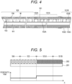
- the treatment instrument channel 141 is configured as illustrated in Fig. 5 such that characteristics of the bending section 103, the first flexible tube portion 101A, and the second flexible tube portion 101B can be maximized.
- Fig. 5 is a cross-sectional view illustrating a cross-sectional structure of the treatment instrument channel 141 and a graph illustrating a characteristic (porosity Rah) thereof.
- the treatment instrument channel 141 has a two-layer structure of an inner layer 201 and an outer layer 202 arranged outside the inner layer 201.
- the inner layer 201 is made of PTFE having a solid structure over the entire length (the distal end portion 104 to the second flexible tube portion 101B) in order to suppress breakage due to contact with the treatment instrument passing through the channel.
- the outer layer 202 is made of porous PTFE.
- the PTFE having the solid structure is hard and has a high resistance to breakage, but is easily buckled, whereas the porous PTFE is flexible and has a low resistance to breakage, but is hardly buckled.
- the treatment instrument channel 141 has the two-layer structure of the PTFE having the solid structure and the porous PTFE, both the resistance to breakage and buckling resistance can be achieved.
- the PTFE having the solid structure of the inner layer 201 is held by the porous PTFE of the outer layer 202 that is hardly buckled, so that a tube that is flexible but hardly buckled can be obtained.
- porous PTFE of the outer layer 202 of the first embodiment has a different porosity Rah depending on a location.
- the porosity Rah of the outer layer 202 is large, the pliability of the treatment instrument channel 141 is enhanced accordingly.
- the outer layer 202 located in the bending section 103 that is bendable by the bending operation knob 102A has q porosity Rah set to about 10 to 40%, for example.
- the outer layer 202 located in the first flexible tube portion 101A and the second flexible tube portion 101B has a higher porosity Rah (for example, 30 to 80% which is a value higher than that of the inside of the bending section 103) than the inside of the bending section 103.
- the bending section 103 Since the degree of bending of the bending section 103 can be adjusted by operating the bending wire W with the bending operation knob 102A, the bending section 103 does not need to have a higher pliability than that of the insertion portion 10. Therefore, it is sufficient for the outer layer 202 in the bending section 103 to have pliability to such an extent that the operation of the bending wire W is not hindered.
- the outer layer 202 of the treatment instrument channel 141 inside the bending section 103 is provided with a smaller porosity than those of the first flexible tube portion 101A and the second flexible tube portion 101B.
- the bending section 103 has pliability to such an extent that the bending wire W can be deformed, and has a high resistance to the buckling.
- the first flexible tube portion 101A and the second flexible tube portion 101B need to be flexibly deformed by the external force based on abutment of the distal end portion 104 or the like on the inner wall of the digestive organ or the like, and to have a higher pliability than that of the bending section 103 in order reduce burden on a patient.
- the outer layer 202 of the treatment instrument channel 141 of the first embodiment is provided with a higher porosity Rah inside the first flexible tube portion 101A and the second flexible tube portion 101B than inside the bending section 103.
- the first flexible tube portion 101A and the second flexible tube portion 101B are provided with a high pliability, and the burden on the patient is reduced.
- the porosities Rah of the first flexible tube portion 101A and the second flexible tube portion 101B are the same in the above example, but different porosities may be given.
- the porosity Rah of the outer layer 202 inside the distal end portion 104 is arbitrary, and may be, for example, the same as the porosity Rah inside the bending section 103. Since the distal end portion 104 is not bent (deformed), the hardness of the treatment instrument channel 141 passing through the distal end portion is irrelevant. Only the outer layer 202 of the distal end portion 104 may be made of the PTFE having the solid structure.
- the treatment instrument channel 141 has the two-layer structure of the inner layer 201 and the outer layer 202, the inner layer 201 is made of polytetrafluoroethylene having a solid structure, the outer layer 202 is made of polytetrafluoroethylene having a porous structure, and the porosity of the outer layer 202 in the bending section 103 is smaller than the porosity of the outer layer 202 in the first flexible tube portion 101A and the second flexible tube portion 101B.
- a certain degree of pliability and a sufficient buckling resistance can be obtained in the bending section 103, while a high pliability can be obtained in the first flexible tube portion 101A and the second flexible tube portion 101B.
- the endoscope that sufficiently exhibits the functions of the flexible tube portion 101 and the bending section 103.
- the two-layer structure is adopted for the treatment instrument channel 141 in the above-described example, but it goes without saying that a similar structure may be adopted for a channel other than the treatment instrument channel 141.
- FIG. 6 The overall configuration of the endoscope of the second embodiment is similar to that of the first embodiment ( Fig. 1 ). Further, configurations of the distal end portion 104, the bending section 103, and the insertion portion 10 are also similar to those of the first embodiment ( Figs. 2 to 3 ) except for the following points.
- the second embodiment is similar to the first embodiment in that the porosity Rah of the outer layer 202 inside the bending section 103 is smaller than the porosity Rah of the outer layer 202 inside the flexible tube portion 101.
- the porosity Rah of the bending section 103 is set to a low value on the distal end portion 104 side, gradually increases at an end portion of the bending section 103 on the first flexible tube portion 101A side, and becomes substantially the same as the porosity Rah inside the first flexible tube portion 101A in the vicinity of a boundary between the bending section 103 and the flexible tube portion 101.
- the porosity Rah of the outer layer 202 inside the distal end portion 104 may be substantially the same as the porosity Rah inside the bending section 103 as in the first embodiment, but may be a value larger than the porosity Rah inside the bending section 103 as illustrated in Fig. 7 .
- the boundary between the bending section 103 and the flexible tube portion 101 does not need to be strictly defined, and can be set at any location in the connecting portion 0103A.
- the function of the bending section 103 can be further enhanced.
- a curvature is small at the end portion on the distal end portion 104 side, and the curvature is large on the flexible tube portion 101 side.
- a buckling resistance can be enhanced at the end portion of the bending section 103 on the distal end portion 104 side, and pliability can be enhanced on the insertion portion 10 side.
- the present invention is not limited to the above-described embodiments, and includes various modifications.
- the above-described embodiments have been described in detail in order to describe the present invention in an easy-to-understand manner, and are not necessarily limited to those having all the described configurations.
- a part of a configuration of a certain embodiment can be replaced with a configuration of another embodiment, and a configuration of another embodiment can be added to a configuration of a certain embodiment.
Landscapes
- Health & Medical Sciences (AREA)
- Life Sciences & Earth Sciences (AREA)
- Surgery (AREA)
- Engineering & Computer Science (AREA)
- Biomedical Technology (AREA)
- Molecular Biology (AREA)
- Pathology (AREA)
- Radiology & Medical Imaging (AREA)
- Nuclear Medicine, Radiotherapy & Molecular Imaging (AREA)
- Biophysics (AREA)
- Physics & Mathematics (AREA)
- Heart & Thoracic Surgery (AREA)
- Medical Informatics (AREA)
- Optics & Photonics (AREA)
- Animal Behavior & Ethology (AREA)
- General Health & Medical Sciences (AREA)
- Public Health (AREA)
- Veterinary Medicine (AREA)
- Manufacturing & Machinery (AREA)
- Endoscopes (AREA)
- Instruments For Viewing The Inside Of Hollow Bodies (AREA)
Claims (2)
- Endoskop, umfassend:einen Einführabschnitt; undeinen in dem Einführabschnitt angeordneten Kanal,wobei der Einführabschnitt Folgendes beinhaltet:einen Biegebereich, der auf Basis einer Tätigkeit biegbar ist; undeinen flexiblen Schlauchabschnitt, der durch eine äußere Kraft, die nicht in Zusammenhang mit der Tätigkeit steht, biegbar ist,wobei der Kanal eine Innenschicht und eine Außenschicht, die außerhalb der Innenschicht ausgebildet ist, beinhaltet,wobei die Innenschicht aus Polytetrafluorethylen, das eine solide Struktur aufweist, hergestellt ist,wobei die Außenschicht aus Polytetrafluorethylen, das eine poröse Struktur aufweist, hergestellt ist, gekennzeichnet dadurch, dass eine Porosität der Außenschicht in dem Biegebereich kleiner ist als eine Porosität der Außenschicht in dem flexiblen Schlauchabschnitt.
- Endoskop nach Anspruch 1, wobei die Porosität der Außenschicht in dem Biegebereich an einem Endabschnitt des flexiblen Schlauchabschnitts schrittweise zunimmt.
Applications Claiming Priority (2)
| Application Number | Priority Date | Filing Date | Title |
|---|---|---|---|
| JP2019190065A JP7372809B2 (ja) | 2019-10-17 | 2019-10-17 | 内視鏡 |
| PCT/JP2020/037103 WO2021075262A1 (ja) | 2019-10-17 | 2020-09-30 | 内視鏡 |
Publications (4)
| Publication Number | Publication Date |
|---|---|
| EP4047409A1 EP4047409A1 (de) | 2022-08-24 |
| EP4047409A4 EP4047409A4 (de) | 2023-11-29 |
| EP4047409B1 true EP4047409B1 (de) | 2024-12-11 |
| EP4047409C0 EP4047409C0 (de) | 2024-12-11 |
Family
ID=75486941
Family Applications (1)
| Application Number | Title | Priority Date | Filing Date |
|---|---|---|---|
| EP20877921.5A Active EP4047409B1 (de) | 2019-10-17 | 2020-09-30 | Endoskop |
Country Status (6)
| Country | Link |
|---|---|
| US (1) | US12318070B2 (de) |
| EP (1) | EP4047409B1 (de) |
| JP (1) | JP7372809B2 (de) |
| CN (1) | CN114599262B (de) |
| ES (1) | ES2998659T3 (de) |
| WO (1) | WO2021075262A1 (de) |
Families Citing this family (3)
| Publication number | Priority date | Publication date | Assignee | Title |
|---|---|---|---|---|
| JP7270829B2 (ja) * | 2020-02-27 | 2023-05-10 | オリンパス株式会社 | 内視鏡、内視鏡の挿入部、内視鏡の製造方法 |
| CN114903409A (zh) * | 2022-05-06 | 2022-08-16 | 深圳市罗伯医疗科技有限公司 | 内镜适配器及内镜手术辅助器械 |
| CN116421127B (zh) * | 2023-03-01 | 2025-11-21 | 浙江优亿医疗器械股份有限公司 | 一种内窥镜及其蛇骨结构 |
Family Cites Families (17)
| Publication number | Priority date | Publication date | Assignee | Title |
|---|---|---|---|---|
| JP3184387B2 (ja) * | 1992-12-25 | 2001-07-09 | ジャパンゴアテックス株式会社 | 可とう性多層チューブ |
| JP3345786B2 (ja) * | 1993-03-17 | 2002-11-18 | ジャパンゴアテックス株式会社 | 可とう性チューブ及びその製造方法 |
| US5789047A (en) | 1993-12-21 | 1998-08-04 | Japan Gore-Tex, Inc | Flexible, multilayered tube |
| US5885209A (en) * | 1996-02-02 | 1999-03-23 | Green; Anthony D. | Endoscopic working channel and method of making same |
| JP3808246B2 (ja) * | 1999-08-09 | 2006-08-09 | オリンパス株式会社 | 内視鏡 |
| US20100256445A1 (en) * | 2006-12-07 | 2010-10-07 | International Polymer Engineering, Inc. | Endoscopic Working Channel and Method of Making Same |
| JP4905785B2 (ja) | 2007-01-18 | 2012-03-28 | 日立工機株式会社 | 電動工具 |
| US8137293B2 (en) * | 2009-11-17 | 2012-03-20 | Boston Scientific Scimed, Inc. | Guidewires including a porous nickel-titanium alloy |
| JP2012136020A (ja) * | 2010-12-09 | 2012-07-19 | Daikin Industries Ltd | 多層チューブ、及び、該多層チューブの製造方法 |
| JP2012153076A (ja) * | 2011-01-28 | 2012-08-16 | Sumitomo Electric Fine Polymer Inc | 可とう性多層チューブ及びその製造方法 |
| WO2013088791A1 (ja) * | 2011-12-16 | 2013-06-20 | オリンパスメディカルシステムズ株式会社 | 樹脂チューブ |
| JP2015175385A (ja) * | 2014-03-13 | 2015-10-05 | 日星電気株式会社 | マルチルーメンチューブ |
| JP6461442B2 (ja) * | 2016-11-09 | 2019-01-30 | オリンパス株式会社 | 内視鏡 |
| JP7274485B2 (ja) * | 2017-12-15 | 2023-05-16 | パーヒューズ・リミテッド | 改善されたカテーテル並びにそうしたカテーテルを組み込んだ装置およびシステム |
| WO2020059643A1 (ja) * | 2018-09-20 | 2020-03-26 | 富士フイルム株式会社 | 内視鏡用チューブ及び内視鏡 |
| CN113164020B (zh) * | 2018-12-12 | 2024-08-06 | 奥林巴斯株式会社 | 内窥镜用通道单元、内窥镜 |
| JP2020171420A (ja) * | 2019-04-09 | 2020-10-22 | オリンパス株式会社 | 医療機器用チューブおよび医療機器 |
-
2019
- 2019-10-17 JP JP2019190065A patent/JP7372809B2/ja active Active
-
2020
- 2020-09-30 ES ES20877921T patent/ES2998659T3/es active Active
- 2020-09-30 US US17/767,214 patent/US12318070B2/en active Active
- 2020-09-30 WO PCT/JP2020/037103 patent/WO2021075262A1/ja not_active Ceased
- 2020-09-30 EP EP20877921.5A patent/EP4047409B1/de active Active
- 2020-09-30 CN CN202080072454.3A patent/CN114599262B/zh active Active
Also Published As
| Publication number | Publication date |
|---|---|
| CN114599262A (zh) | 2022-06-07 |
| EP4047409A1 (de) | 2022-08-24 |
| EP4047409C0 (de) | 2024-12-11 |
| JP7372809B2 (ja) | 2023-11-01 |
| US12318070B2 (en) | 2025-06-03 |
| EP4047409A4 (de) | 2023-11-29 |
| US20220369896A1 (en) | 2022-11-24 |
| WO2021075262A1 (ja) | 2021-04-22 |
| CN114599262B (zh) | 2025-08-22 |
| JP2021062169A (ja) | 2021-04-22 |
| ES2998659T3 (en) | 2025-02-21 |
Similar Documents
| Publication | Publication Date | Title |
|---|---|---|
| EP4047409B1 (de) | Endoskop | |
| JP5390048B1 (ja) | 内視鏡システム | |
| EP4094671B1 (de) | Multifunktionskatheter | |
| EP2896348A1 (de) | Reinigungshülle für endoskop und endoskopvorrichtung | |
| CN103889306B (zh) | 电子内窥镜装置 | |
| EP4062820B1 (de) | Endoskop | |
| JPH07308283A (ja) | カバー方式内視鏡 | |
| US12171404B2 (en) | Endoscope | |
| JPH10192223A (ja) | 内視鏡 | |
| EP2394568A1 (de) | Endoskop | |
| JP3762600B2 (ja) | 電子内視鏡 | |
| JP2020075043A (ja) | 内視鏡 | |
| JP2009183619A (ja) | 内視鏡 |
Legal Events
| Date | Code | Title | Description |
|---|---|---|---|
| STAA | Information on the status of an ep patent application or granted ep patent |
Free format text: STATUS: THE INTERNATIONAL PUBLICATION HAS BEEN MADE |
|
| PUAI | Public reference made under article 153(3) epc to a published international application that has entered the european phase |
Free format text: ORIGINAL CODE: 0009012 |
|
| STAA | Information on the status of an ep patent application or granted ep patent |
Free format text: STATUS: REQUEST FOR EXAMINATION WAS MADE |
|
| 17P | Request for examination filed |
Effective date: 20220512 |
|
| AK | Designated contracting states |
Kind code of ref document: A1 Designated state(s): AL AT BE BG CH CY CZ DE DK EE ES FI FR GB GR HR HU IE IS IT LI LT LU LV MC MK MT NL NO PL PT RO RS SE SI SK SM TR |
|
| DAV | Request for validation of the european patent (deleted) | ||
| DAX | Request for extension of the european patent (deleted) | ||
| A4 | Supplementary search report drawn up and despatched |
Effective date: 20231027 |
|
| RIC1 | Information provided on ipc code assigned before grant |
Ipc: A61M 25/01 20060101ALI20231023BHEP Ipc: A61M 25/00 20060101ALI20231023BHEP Ipc: A61B 1/005 20060101ALI20231023BHEP Ipc: G02B 23/24 20060101AFI20231023BHEP |
|
| GRAP | Despatch of communication of intention to grant a patent |
Free format text: ORIGINAL CODE: EPIDOSNIGR1 |
|
| STAA | Information on the status of an ep patent application or granted ep patent |
Free format text: STATUS: GRANT OF PATENT IS INTENDED |
|
| INTG | Intention to grant announced |
Effective date: 20240710 |
|
| RIN1 | Information on inventor provided before grant (corrected) |
Inventor name: HIRAYAMA, TETSU |
|
| GRAS | Grant fee paid |
Free format text: ORIGINAL CODE: EPIDOSNIGR3 |
|
| GRAA | (expected) grant |
Free format text: ORIGINAL CODE: 0009210 |
|
| STAA | Information on the status of an ep patent application or granted ep patent |
Free format text: STATUS: THE PATENT HAS BEEN GRANTED |
|
| AK | Designated contracting states |
Kind code of ref document: B1 Designated state(s): AL AT BE BG CH CY CZ DE DK EE ES FI FR GB GR HR HU IE IS IT LI LT LU LV MC MK MT NL NO PL PT RO RS SE SI SK SM TR |
|
| REG | Reference to a national code |
Ref country code: GB Ref legal event code: FG4D |
|
| REG | Reference to a national code |
Ref country code: CH Ref legal event code: EP |
|
| REG | Reference to a national code |
Ref country code: IE Ref legal event code: FG4D |
|
| REG | Reference to a national code |
Ref country code: DE Ref legal event code: R096 Ref document number: 602020043134 Country of ref document: DE |
|
| U01 | Request for unitary effect filed |
Effective date: 20250110 |
|
| U07 | Unitary effect registered |
Designated state(s): AT BE BG DE DK EE FI FR IT LT LU LV MT NL PT RO SE SI Effective date: 20250116 |
|
| REG | Reference to a national code |
Ref country code: ES Ref legal event code: FG2A Ref document number: 2998659 Country of ref document: ES Kind code of ref document: T3 Effective date: 20250221 |
|
| PG25 | Lapsed in a contracting state [announced via postgrant information from national office to epo] |
Ref country code: HR Free format text: LAPSE BECAUSE OF FAILURE TO SUBMIT A TRANSLATION OF THE DESCRIPTION OR TO PAY THE FEE WITHIN THE PRESCRIBED TIME-LIMIT Effective date: 20241211 |
|
| PG25 | Lapsed in a contracting state [announced via postgrant information from national office to epo] |
Ref country code: NO Free format text: LAPSE BECAUSE OF FAILURE TO SUBMIT A TRANSLATION OF THE DESCRIPTION OR TO PAY THE FEE WITHIN THE PRESCRIBED TIME-LIMIT Effective date: 20250311 |
|
| PG25 | Lapsed in a contracting state [announced via postgrant information from national office to epo] |
Ref country code: GR Free format text: LAPSE BECAUSE OF FAILURE TO SUBMIT A TRANSLATION OF THE DESCRIPTION OR TO PAY THE FEE WITHIN THE PRESCRIBED TIME-LIMIT Effective date: 20250312 |
|
| PG25 | Lapsed in a contracting state [announced via postgrant information from national office to epo] |
Ref country code: RS Free format text: LAPSE BECAUSE OF FAILURE TO SUBMIT A TRANSLATION OF THE DESCRIPTION OR TO PAY THE FEE WITHIN THE PRESCRIBED TIME-LIMIT Effective date: 20250311 |
|
| PG25 | Lapsed in a contracting state [announced via postgrant information from national office to epo] |
Ref country code: SM Free format text: LAPSE BECAUSE OF FAILURE TO SUBMIT A TRANSLATION OF THE DESCRIPTION OR TO PAY THE FEE WITHIN THE PRESCRIBED TIME-LIMIT Effective date: 20241211 |
|
| PG25 | Lapsed in a contracting state [announced via postgrant information from national office to epo] |
Ref country code: PL Free format text: LAPSE BECAUSE OF FAILURE TO SUBMIT A TRANSLATION OF THE DESCRIPTION OR TO PAY THE FEE WITHIN THE PRESCRIBED TIME-LIMIT Effective date: 20241211 |
|
| PG25 | Lapsed in a contracting state [announced via postgrant information from national office to epo] |
Ref country code: IS Free format text: LAPSE BECAUSE OF FAILURE TO SUBMIT A TRANSLATION OF THE DESCRIPTION OR TO PAY THE FEE WITHIN THE PRESCRIBED TIME-LIMIT Effective date: 20250411 |
|
| PG25 | Lapsed in a contracting state [announced via postgrant information from national office to epo] |
Ref country code: SK Free format text: LAPSE BECAUSE OF FAILURE TO SUBMIT A TRANSLATION OF THE DESCRIPTION OR TO PAY THE FEE WITHIN THE PRESCRIBED TIME-LIMIT Effective date: 20241211 |
|
| PG25 | Lapsed in a contracting state [announced via postgrant information from national office to epo] |
Ref country code: CZ Free format text: LAPSE BECAUSE OF FAILURE TO SUBMIT A TRANSLATION OF THE DESCRIPTION OR TO PAY THE FEE WITHIN THE PRESCRIBED TIME-LIMIT Effective date: 20241211 |
|
| U20 | Renewal fee for the european patent with unitary effect paid |
Year of fee payment: 6 Effective date: 20250807 |
|
| PGFP | Annual fee paid to national office [announced via postgrant information from national office to epo] |
Ref country code: GB Payment date: 20250807 Year of fee payment: 6 |
|
| PLBE | No opposition filed within time limit |
Free format text: ORIGINAL CODE: 0009261 |
|
| STAA | Information on the status of an ep patent application or granted ep patent |
Free format text: STATUS: NO OPPOSITION FILED WITHIN TIME LIMIT |
|
| 26N | No opposition filed |
Effective date: 20250912 |
|
| PGFP | Annual fee paid to national office [announced via postgrant information from national office to epo] |
Ref country code: ES Payment date: 20251013 Year of fee payment: 6 |