EP4046879B1 - Dispositif de protection pour une face avant de cabine de véhicule de travail - Google Patents
Dispositif de protection pour une face avant de cabine de véhicule de travail Download PDFInfo
- Publication number
- EP4046879B1 EP4046879B1 EP22157863.6A EP22157863A EP4046879B1 EP 4046879 B1 EP4046879 B1 EP 4046879B1 EP 22157863 A EP22157863 A EP 22157863A EP 4046879 B1 EP4046879 B1 EP 4046879B1
- Authority
- EP
- European Patent Office
- Prior art keywords
- protection
- mobile
- fixed foot
- work vehicle
- grid
- Prior art date
- Legal status (The legal status is an assumption and is not a legal conclusion. Google has not performed a legal analysis and makes no representation as to the accuracy of the status listed.)
- Active
Links
Images


Classifications
-
- B—PERFORMING OPERATIONS; TRANSPORTING
- B60—VEHICLES IN GENERAL
- B60R—VEHICLES, VEHICLE FITTINGS, OR VEHICLE PARTS, NOT OTHERWISE PROVIDED FOR
- B60R21/00—Arrangements or fittings on vehicles for protecting or preventing injuries to occupants or pedestrians in case of accidents or other traffic risks
- B60R21/02—Occupant safety arrangements or fittings, e.g. crash pads
- B60R21/11—Overhead guards, e.g. against loads falling down
-
- E—FIXED CONSTRUCTIONS
- E02—HYDRAULIC ENGINEERING; FOUNDATIONS; SOIL SHIFTING
- E02F—DREDGING; SOIL-SHIFTING
- E02F9/00—Component parts of dredgers or soil-shifting machines, not restricted to one of the kinds covered by groups E02F3/00 - E02F7/00
- E02F9/16—Cabins, platforms, or the like, for drivers
- E02F9/163—Structures to protect drivers, e.g. cabins, doors for cabins; Falling object protection structure [FOPS]; Roll over protection structure [ROPS]
Definitions
- the invention relates to a protective device for a work vehicle cab front according to the preamble of claim 1.
- a cab protection for an excavator comprising a front protective grille and a cab canopy, the front protective grille being able to be pushed at least partially into the cab protective roof, the front protective grille comprising an upper part and a lower part.
- the GB 2 430 696 A and the JP 2004 074 853 A disclose further cabin protection devices known from the prior art.
- JP 201 2 1 62932 A to name which discloses a protective device for a work vehicle cab front, which is accessible.
- JP 201 1 084876 A cite discloses a front protection bar mounting device for a construction machine, which allows a front protection bar to be exchanged.
- a protective device for a working vehicle cab front according to the preamble of claim 1 is by the JP H 09 228 422 A disclosed.
- the object of the present invention is to overcome the disadvantages of the prior art.
- a protective device should be provided in which it should be easier for the user to open a viewing window in the front protective grille.
- the protective device according to the invention serves to protect a work vehicle cab front.
- This is a protective device that can be attached to the front of a cabin and consists of a front safety device.
- the front guard curves slightly away from the front of the cab, with the front guard consisting of a fixed foot guard and a mobile guard. It is envisaged that the design of the front safety device is adapted to the circumstances of the respective cabin front.
- the fixed foot protection is designed in such a way that it cannot be moved and covers about half of the work vehicle cab front and thus the window mounted there.
- an adaptation to the respective work vehicle cab front is provided here, so that the cover of the fixed foot protection can also be well below half of the work vehicle cab front.
- the lower area is that area which, when the protective device is properly installed, is arranged towards a subsurface on which the work vehicle can move accordingly.
- the above is defined within the scope of the invention as being located away from the ground on which the vehicle can move.
- the mobile protection represents the part of the front protection which can be moved out of the field of vision of the user sitting in the working vehicle cab in order to be able to provide the view free of the mobile protection. This can be the case, for example, if the user does not actually need the front safety device due to the lack of danger and would like to have a better view of the working area of his work vehicle.
- the mobile protection In a closed position, the mobile protection is arranged complementarily on the fixed foot protection.
- the wording according to which the mobile protection is arranged in the closed position on or above the fixed foot protection is to be understood in such a way that in the closed position the mobile protection forms a visual unit with the fixed foot protection.
- the mobile protection is folded down in an open position and is arranged in front of the fixed foot protection.
- Folded down means in this context that the mobile protection can be folded towards a base.
- the arrangement in front of the fixed foot protection means that the mobile protection is folded down in such a way that it moves away from the work vehicle cab front, in order to then arrive in an open position in front of the fixed foot protection.
- the fixed foot protection is arranged in the open position between the mobile protection and the cab front of the work vehicle.
- This swivel link supports the folding down of the mobile protection in the open position and the folding up of the mobile protection in the closed position. Folding upwards here means that it is essentially in the opposite direction to the ground.
- a gas pressure spring is arranged between the fixed foot protection and the mobile protection.
- the gas pressure spring can support the downward folding of the mobile protection in such a way that the gas pressure spring, for example, accompanies a hinge or a lever construction downwards and develops force upwards.
- the gas pressure spring is arranged in such a way that it enters into an operative connection with the pivot link.
- the gas pressure spring is arranged between the fixed foot protection and the pivot link.
- the swivel link can preferably be a four-point rotation lever construction, with the gas pressure spring again acting as a force absorber on part of the swivel link, during the opening process acting as a force emitter and during the closing process on the four points of the rotation lever construction, which are designed as joints acts. There is also an open lock.
- the open lock serves to fix the handset to the fixed foot protection in the open position. In this way, it is advantageously prevented that the mobile protection unintentionally pivots upwards in the open position.
- the closing lock advantageously serves to ensure that the mobile protection is above the fixed foot protection in the closed position can be locked or fixed in order to prevent the mobile protection from swiveling away unintentionally.
- the front safety can have a fixed head protection.
- the fixed head protection is present in such a way that it is designed above the mobile protection arranged in the closed position.
- the fixed head protection like the fixed foot protection, is usually firmly and immovably connected to the work vehicle cab. In the closed position, the mobile protection is therefore arranged between the fixed foot protection and the fixed head protection.
- the fixed foot protection is connected to the fixed head protection via two ridges on the edge.
- the two edge bars also form a frame into which the mobile protection can move in or out in the closed position.
- the two ridges on the edge give the front safety device the appropriate strength during work.
- each of the two edge-side webs has at least one fitting plate. These are fitting plates attached to the two edge webs, which can lead the mobile protection to the closed position and thereby additionally increase the strength.
- a handle is also provided on the mobile protection, since the mobile protection can easily be folded down manually by the user, for example with or against the force of the gas pressure spring, due to its low weight. In the same way, the mobile protection can also be easily pivoted into the closed position by the user with or against the force of the gas pressure spring.
- Mobile protection is a first in a preferred embodiment grid executed.
- the fixed foot protection is designed as a second grid.
- the first grille comes to rest on the second grille.
- any lattice struts running from bottom to top are arranged in a common linear extension.
- the first grid comes to rest on the second grid in such a way that the grid struts of the first and second grid form a common widening in an extension away from the work vehicle cab, so that the length running from bottom to top does not increase of the fixed foot protection is lengthened, but the width running away from the work vehicle cab front is widened by the bars of the mobile protection.
- the lattice bars have a depth of 1 to 4 cm, arranged away from the front of the cabin, and a width of 4 to 8 mm, arranged essentially at right angles to the depth. In this way, the user always has a perfect view of his work area.
- This has the advantage that the protective device can be applied and fastened to existing work vehicle cab fronts in a simple manner.
- This can be, for example, angle plates, which are connected to the protective device on the one hand and can be connected to the cab front of the working vehicle on the other.
- the cab roof protection extends over a roof of the work vehicle cab and, in addition to the front, also protects the roof area of the work vehicle cab. All essential parts can be made of a metallic material here.
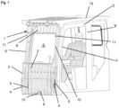
- a work vehicle cab B can be seen.
- the work vehicle cab B has a work vehicle cab front F.
- the work vehicle cab B has a work vehicle cab roof D.
- the protective device consists primarily of a front safety device 1, with the front safety device 1 consisting of a fixed foot protection 2 and a mobile protection 3.
- the open position shown is that the mobile protection 1 is folded down to a surface that is not shown in detail here and is arranged in front of the fixed foot protection 2 . You can continue in the figure 1 recognize well that in the open position a viewing window S is created in the front lock 1, with the view always being guaranteed even in the closed position.
- a pivot link 4 is also shown, with a second pivot link 4 being present here.
- the two swivel links 4 are arranged on the side of the front safety device 1 in such a way that they should allow the mobile protection 3 to be folded up and down.
- a gas pressure spring 5 which supports the respective pivot link 4 connected to it in a force-receiving or force-emitting manner.
- an open locking mechanism 6 is used, which is designed in such a way that, for example, a spring-loaded dowel pin of the mobile protection 3 can move into a corresponding receptacle in the fixed foot protection 2 .
- the open lock 6 is located on the downward-pointing end of the mobile protection 3 and the fixed foot protection 2.
- a handle 12 is also provided.
- the handle 12 is arranged on the mobile protection 3 . In doing so, it protrudes from the mobile protection 3 .
- other constructions of a handle for handling the mobile protection device 3 are also possible.
- the handle 12 is arranged in the open position away from the fixed foot protection 2 on the mobile protection 3 .
- a hard head guard 8 Also shown as part of the front guard 1 is a hard head guard 8 .
- the fixed head protection 8 is arranged above the viewing window S.
- the fixed head protection 8 is connected to the fixed foot protection 2 via two webs 9, 10 on the edge.
- the two edge webs 9 , 10 each have a fitting plate 11 .
- the number, shape and design of the fitting plates 11 is due to the respective requirement.
- a connection, not shown in detail, of the front safety device 1 to the cab protective roof 15 is also present.
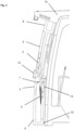
- a middle position is shown.
- the mobile protection 3 In the middle position, the mobile protection 3 is in a position between the open position and the closed position. There it is easy to see in the side view how the pressure spring 5 is partially extended and the mobile protection 3 has become detached from the fixed foot protection 2 and has not yet reached the viewing window S between the two webs 9, 10.
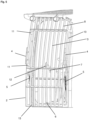
- the one in the figure 4 shown closed position is in the figure 5 shown again from an oblique front view. It is also easy to see how the bars of a first bar of the mobile protection 3 are arranged in the closed position in the extension of the bars of the second bar of the fixed foot protection 2 and form a common linear extension.
- figure 2 is shown how in the open position the bars of the first grid of the mobile protection 3 rest on the bars of the second grid of the fixed foot protection 2 and widen the overall construction.
Landscapes
- Engineering & Computer Science (AREA)
- Mining & Mineral Resources (AREA)
- Civil Engineering (AREA)
- General Engineering & Computer Science (AREA)
- Structural Engineering (AREA)
- Mechanical Engineering (AREA)
- Component Parts Of Construction Machinery (AREA)
- Body Structure For Vehicles (AREA)
Claims (12)
- Dispositif de protection pour une face avant de cabine de véhicule de travail, composé d'une protection frontale (1), la protection frontale (1) étant composée d'une protection fixe de pied (2) et d'une protection mobile (3), dans une position fermée la protection mobile (3) étant disposée de façon complémentaire sur la protection fixe de pied (2), dans une position ouverte la protection mobile (3) étant repliée vers le bas et ainsi disposée devant la protection fixe de pied (2)
caractérisé en ce que
une coulisse de pivotement (4) est présente entre la protection fixe de pied (2) et la protection mobile (3), un ressort pneumatique (5) étant disposé entre la protection fixe de pied (2) et la protection mobile (3) ou la coulisse de pivotement (4). - Dispositif de protection selon l'une des revendications précédentes, caractérisé en ce qu'un dispositif de blocage d'ouverture (6) est présent.
- Dispositif de protection selon l'une des revendications précédentes, caractérisé en ce qu'un dispositif de blocage de fermeture (7) est présent.
- Dispositif de protection selon l'une des revendications précédentes, caractérisé en ce qu'une protection fixe de tête (8) est présente.
- Dispositif de protection selon la revendication 4, caractérisé en ce que, dans la position fermée, la protection mobile (3) est disposée entre la protection fixe de pied (2) et la protection fixe de tête (8).
- Dispositif de protection selon la revendication 4, caractérisé en ce que la protection fixe de pied (2) est reliée à la protection fixe de tête (8) par l'intermédiaire de deux traverses (9, 10) latérales.
- Dispositif de protection selon la revendication 6,
caractérisé en ce qu'une plaque d'ajustement (11) est présente respectivement pour les deux traverses (9, 10) latérales. - Dispositif de protection selon l'une des revendications précédentes, caractérisé en ce que la protection mobile (3) présente une poignée (12).
- Dispositif de protection selon l'une des revendications précédentes, caractérisé en ce que la protection mobile (3) présente une première grille et la protection fixe de pied (2) présente une seconde grille, dans la position ouverte la première grille venant se poser sur la seconde grille et dans la position fermée la première grille étant disposée dans la prolongation de la seconde grille.
- Dispositif de protection selon l'une des revendications précédentes, caractérisé en ce qu'un dispositif d'attache de cabine (13) est présent.
- Dispositif de protection selon l'une des revendications précédentes, caractérisé en ce qu'une liaison à une protection de toit de cabine (15) est présente.
- Utilisation d'un dispositif de protection selon l'une des revendications 1 à 11 pour la liaison à une cabine de véhicule de travail.
Applications Claiming Priority (1)
| Application Number | Priority Date | Filing Date | Title |
|---|---|---|---|
| DE102021104164.3A DE102021104164B3 (de) | 2021-02-22 | 2021-02-22 | Schutzeinrichtung für eine Arbeitsfahrzeug-Kabinenfront |
Publications (2)
| Publication Number | Publication Date |
|---|---|
| EP4046879A1 EP4046879A1 (fr) | 2022-08-24 |
| EP4046879B1 true EP4046879B1 (fr) | 2023-08-09 |
Family
ID=80447021
Family Applications (1)
| Application Number | Title | Priority Date | Filing Date |
|---|---|---|---|
| EP22157863.6A Active EP4046879B1 (fr) | 2021-02-22 | 2022-02-22 | Dispositif de protection pour une face avant de cabine de véhicule de travail |
Country Status (2)
| Country | Link |
|---|---|
| EP (1) | EP4046879B1 (fr) |
| DE (1) | DE102021104164B3 (fr) |
Families Citing this family (2)
| Publication number | Priority date | Publication date | Assignee | Title |
|---|---|---|---|---|
| CN117465564B (zh) * | 2023-12-28 | 2024-03-22 | 高邮市迅达工程机械集团有限公司 | 一种工程车辆驾驶室以及工程车辆 |
| CN120739193B (zh) * | 2025-09-01 | 2025-11-14 | 福建省新华都工程有限责任公司 | 一种矿用挖掘机防护罩 |
Family Cites Families (11)
| Publication number | Priority date | Publication date | Assignee | Title |
|---|---|---|---|---|
| JPS6091649U (ja) | 1983-11-29 | 1985-06-22 | 日立建機株式会社 | 作業機用ヘツドガ−ド |
| DE4404415A1 (de) | 1994-02-11 | 1995-08-17 | Caterpillar Inc | Fahrerhaus für ein Fahrzeug insbesondere einen Bagger und Frontfenster dafür |
| JPH08100442A (ja) | 1994-09-30 | 1996-04-16 | Yutani Heavy Ind Ltd | 建設機械のキャブガード装置 |
| JPH09228422A (ja) | 1996-02-22 | 1997-09-02 | Hitachi Constr Mach Co Ltd | 建設機械運転室のガード |
| JP2003232053A (ja) | 2002-02-07 | 2003-08-19 | Sumitomo (Shi) Construction Machinery Manufacturing Co Ltd | 作業機のキャブガード装置 |
| JP2004074853A (ja) | 2002-08-12 | 2004-03-11 | Shin Caterpillar Mitsubishi Ltd | キャブ |
| KR100903981B1 (ko) | 2005-05-13 | 2009-06-25 | 가부시키가이샤 고마쓰 세이사쿠쇼 | 작업기계용 캡 |
| JP5173976B2 (ja) * | 2009-10-13 | 2013-04-03 | 日立建機株式会社 | 建設機械のフロントガード取付装置 |
| JP2012162932A (ja) | 2011-02-08 | 2012-08-30 | Hitachi Constr Mach Co Ltd | 建設機械の運転室ガラスのガード構造 |
| DE102012102140A1 (de) | 2012-03-12 | 2013-09-12 | Echle Hartstahl Gmbh | Kabinenschutz |
| DE102014105868A1 (de) | 2014-04-25 | 2015-10-29 | Jürgen Wolf | Schutzvorrichtung für eine Fahrerkabine eines Nutzfahrzeugs |
-
2021
- 2021-02-22 DE DE102021104164.3A patent/DE102021104164B3/de active Active
-
2022
- 2022-02-22 EP EP22157863.6A patent/EP4046879B1/fr active Active
Also Published As
| Publication number | Publication date |
|---|---|
| DE102021104164B3 (de) | 2022-07-07 |
| EP4046879A1 (fr) | 2022-08-24 |
Similar Documents
| Publication | Publication Date | Title |
|---|---|---|
| DE10005196B4 (de) | Kopfstütze an einem Fahrzeugsitz | |
| DE10136897A1 (de) | Doppelarmgelenkscharnier für die Fronthaube eines Kraftfahrzeuges | |
| WO2013102456A1 (fr) | Grille de barrière | |
| EP1305192B1 (fr) | Systeme de protection de conducteur pour engins mobiles | |
| EP4046879B1 (fr) | Dispositif de protection pour une face avant de cabine de véhicule de travail | |
| DE10307149A1 (de) | Klappbarer Fahrzeugsitz | |
| DE10128101B4 (de) | Ährenheber | |
| EP0483533A1 (fr) | Cabine de véhicule, en particulier pour un tracteur industriel | |
| DE29921860U1 (de) | Fensterrollo für ein Dreiecksfenster eines Kraftfahrzeugs | |
| EP3708439A1 (fr) | Charnière d'articulation pour capot soulevable | |
| EP0265882A1 (fr) | Dispositif de fixation d'une pelle rétro avec un engin de terrassement | |
| DE102014012196B4 (de) | Scharnier für eine Frontklappe eines Kraftfahrzeugs | |
| DE6800555U (de) | Verschliessbarer behaelter zur aufnahme von werkzeugen, der batterie od. dgl. | |
| DE4021779B4 (de) | Sicherungsschere | |
| DE10207408C1 (de) | Vorrichtung für die zeitweilige geschützte Halterung einer unteren Scheibe der Fahrerkabine eines schweren Geräts in der Fahrerkabine | |
| EP0043529B1 (fr) | Siège de véhicule, en particulier siège rabattable pour véhicule agricole | |
| DE10314073B4 (de) | Stützeinrichtung an einer verstellbaren Fahrzeughaube | |
| DE19840909B4 (de) | Sicherheitsanhaltevorrichtung für einen Kran | |
| EP1957739B1 (fr) | Dispositif de protection d'arête | |
| EP1464213B1 (fr) | Dispositif de protection contre surcharge pour une machine de travail du sol | |
| EP2277746B1 (fr) | Véhicule automobile doté d'un capot avant | |
| DE1533582C (de) | Rollenblock für Hebezeuge | |
| DE102023123535A1 (de) | Laufwagenanordnung mit montagehilfe zur anbringung an einem hebe-schiebeelement | |
| AT2232U1 (de) | Klapptisch | |
| DE1996050U (de) | Hebelschneidmaschine |
Legal Events
| Date | Code | Title | Description |
|---|---|---|---|
| PUAI | Public reference made under article 153(3) epc to a published international application that has entered the european phase |
Free format text: ORIGINAL CODE: 0009012 |
|
| STAA | Information on the status of an ep patent application or granted ep patent |
Free format text: STATUS: THE APPLICATION HAS BEEN PUBLISHED |
|
| AK | Designated contracting states |
Kind code of ref document: A1 Designated state(s): AL AT BE BG CH CY CZ DE DK EE ES FI FR GB GR HR HU IE IS IT LI LT LU LV MC MK MT NL NO PL PT RO RS SE SI SK SM TR |
|
| STAA | Information on the status of an ep patent application or granted ep patent |
Free format text: STATUS: REQUEST FOR EXAMINATION WAS MADE |
|
| GRAP | Despatch of communication of intention to grant a patent |
Free format text: ORIGINAL CODE: EPIDOSNIGR1 |
|
| STAA | Information on the status of an ep patent application or granted ep patent |
Free format text: STATUS: GRANT OF PATENT IS INTENDED |
|
| 17P | Request for examination filed |
Effective date: 20230112 |
|
| RBV | Designated contracting states (corrected) |
Designated state(s): AL AT BE BG CH CY CZ DE DK EE ES FI FR GB GR HR HU IE IS IT LI LT LU LV MC MK MT NL NO PL PT RO RS SE SI SK SM TR |
|
| INTG | Intention to grant announced |
Effective date: 20230214 |
|
| GRAS | Grant fee paid |
Free format text: ORIGINAL CODE: EPIDOSNIGR3 |
|
| GRAA | (expected) grant |
Free format text: ORIGINAL CODE: 0009210 |
|
| STAA | Information on the status of an ep patent application or granted ep patent |
Free format text: STATUS: THE PATENT HAS BEEN GRANTED |
|
| AK | Designated contracting states |
Kind code of ref document: B1 Designated state(s): AL AT BE BG CH CY CZ DE DK EE ES FI FR GB GR HR HU IE IS IT LI LT LU LV MC MK MT NL NO PL PT RO RS SE SI SK SM TR |
|
| REG | Reference to a national code |
Ref country code: GB Ref legal event code: FG4D Free format text: NOT ENGLISH |
|
| REG | Reference to a national code |
Ref country code: CH Ref legal event code: EP |
|
| REG | Reference to a national code |
Ref country code: DE Ref legal event code: R096 Ref document number: 502022000076 Country of ref document: DE |
|
| REG | Reference to a national code |
Ref country code: IE Ref legal event code: FG4D Free format text: LANGUAGE OF EP DOCUMENT: GERMAN |
|
| REG | Reference to a national code |
Ref country code: NL Ref legal event code: FP |
|
| P01 | Opt-out of the competence of the unified patent court (upc) registered |
Effective date: 20230915 |
|
| REG | Reference to a national code |
Ref country code: LT Ref legal event code: MG9D |
|
| PG25 | Lapsed in a contracting state [announced via postgrant information from national office to epo] |
Ref country code: GR Free format text: LAPSE BECAUSE OF FAILURE TO SUBMIT A TRANSLATION OF THE DESCRIPTION OR TO PAY THE FEE WITHIN THE PRESCRIBED TIME-LIMIT Effective date: 20231110 |
|
| PG25 | Lapsed in a contracting state [announced via postgrant information from national office to epo] |
Ref country code: IS Free format text: LAPSE BECAUSE OF FAILURE TO SUBMIT A TRANSLATION OF THE DESCRIPTION OR TO PAY THE FEE WITHIN THE PRESCRIBED TIME-LIMIT Effective date: 20231209 |
|
| PG25 | Lapsed in a contracting state [announced via postgrant information from national office to epo] |
Ref country code: SE Free format text: LAPSE BECAUSE OF FAILURE TO SUBMIT A TRANSLATION OF THE DESCRIPTION OR TO PAY THE FEE WITHIN THE PRESCRIBED TIME-LIMIT Effective date: 20230809 Ref country code: RS Free format text: LAPSE BECAUSE OF FAILURE TO SUBMIT A TRANSLATION OF THE DESCRIPTION OR TO PAY THE FEE WITHIN THE PRESCRIBED TIME-LIMIT Effective date: 20230809 Ref country code: PT Free format text: LAPSE BECAUSE OF FAILURE TO SUBMIT A TRANSLATION OF THE DESCRIPTION OR TO PAY THE FEE WITHIN THE PRESCRIBED TIME-LIMIT Effective date: 20231211 Ref country code: NO Free format text: LAPSE BECAUSE OF FAILURE TO SUBMIT A TRANSLATION OF THE DESCRIPTION OR TO PAY THE FEE WITHIN THE PRESCRIBED TIME-LIMIT Effective date: 20231109 Ref country code: LV Free format text: LAPSE BECAUSE OF FAILURE TO SUBMIT A TRANSLATION OF THE DESCRIPTION OR TO PAY THE FEE WITHIN THE PRESCRIBED TIME-LIMIT Effective date: 20230809 Ref country code: LT Free format text: LAPSE BECAUSE OF FAILURE TO SUBMIT A TRANSLATION OF THE DESCRIPTION OR TO PAY THE FEE WITHIN THE PRESCRIBED TIME-LIMIT Effective date: 20230809 Ref country code: IS Free format text: LAPSE BECAUSE OF FAILURE TO SUBMIT A TRANSLATION OF THE DESCRIPTION OR TO PAY THE FEE WITHIN THE PRESCRIBED TIME-LIMIT Effective date: 20231209 Ref country code: HR Free format text: LAPSE BECAUSE OF FAILURE TO SUBMIT A TRANSLATION OF THE DESCRIPTION OR TO PAY THE FEE WITHIN THE PRESCRIBED TIME-LIMIT Effective date: 20230809 Ref country code: GR Free format text: LAPSE BECAUSE OF FAILURE TO SUBMIT A TRANSLATION OF THE DESCRIPTION OR TO PAY THE FEE WITHIN THE PRESCRIBED TIME-LIMIT Effective date: 20231110 Ref country code: FI Free format text: LAPSE BECAUSE OF FAILURE TO SUBMIT A TRANSLATION OF THE DESCRIPTION OR TO PAY THE FEE WITHIN THE PRESCRIBED TIME-LIMIT Effective date: 20230809 |
|
| PG25 | Lapsed in a contracting state [announced via postgrant information from national office to epo] |
Ref country code: PL Free format text: LAPSE BECAUSE OF FAILURE TO SUBMIT A TRANSLATION OF THE DESCRIPTION OR TO PAY THE FEE WITHIN THE PRESCRIBED TIME-LIMIT Effective date: 20230809 |
|
| PG25 | Lapsed in a contracting state [announced via postgrant information from national office to epo] |
Ref country code: ES Free format text: LAPSE BECAUSE OF FAILURE TO SUBMIT A TRANSLATION OF THE DESCRIPTION OR TO PAY THE FEE WITHIN THE PRESCRIBED TIME-LIMIT Effective date: 20230809 |
|
| PG25 | Lapsed in a contracting state [announced via postgrant information from national office to epo] |
Ref country code: SM Free format text: LAPSE BECAUSE OF FAILURE TO SUBMIT A TRANSLATION OF THE DESCRIPTION OR TO PAY THE FEE WITHIN THE PRESCRIBED TIME-LIMIT Effective date: 20230809 Ref country code: RO Free format text: LAPSE BECAUSE OF FAILURE TO SUBMIT A TRANSLATION OF THE DESCRIPTION OR TO PAY THE FEE WITHIN THE PRESCRIBED TIME-LIMIT Effective date: 20230809 Ref country code: ES Free format text: LAPSE BECAUSE OF FAILURE TO SUBMIT A TRANSLATION OF THE DESCRIPTION OR TO PAY THE FEE WITHIN THE PRESCRIBED TIME-LIMIT Effective date: 20230809 Ref country code: EE Free format text: LAPSE BECAUSE OF FAILURE TO SUBMIT A TRANSLATION OF THE DESCRIPTION OR TO PAY THE FEE WITHIN THE PRESCRIBED TIME-LIMIT Effective date: 20230809 Ref country code: DK Free format text: LAPSE BECAUSE OF FAILURE TO SUBMIT A TRANSLATION OF THE DESCRIPTION OR TO PAY THE FEE WITHIN THE PRESCRIBED TIME-LIMIT Effective date: 20230809 Ref country code: CZ Free format text: LAPSE BECAUSE OF FAILURE TO SUBMIT A TRANSLATION OF THE DESCRIPTION OR TO PAY THE FEE WITHIN THE PRESCRIBED TIME-LIMIT Effective date: 20230809 Ref country code: SK Free format text: LAPSE BECAUSE OF FAILURE TO SUBMIT A TRANSLATION OF THE DESCRIPTION OR TO PAY THE FEE WITHIN THE PRESCRIBED TIME-LIMIT Effective date: 20230809 |
|
| REG | Reference to a national code |
Ref country code: DE Ref legal event code: R097 Ref document number: 502022000076 Country of ref document: DE |
|
| PLBE | No opposition filed within time limit |
Free format text: ORIGINAL CODE: 0009261 |
|
| STAA | Information on the status of an ep patent application or granted ep patent |
Free format text: STATUS: NO OPPOSITION FILED WITHIN TIME LIMIT |
|
| 26N | No opposition filed |
Effective date: 20240513 |
|
| PG25 | Lapsed in a contracting state [announced via postgrant information from national office to epo] |
Ref country code: SI Free format text: LAPSE BECAUSE OF FAILURE TO SUBMIT A TRANSLATION OF THE DESCRIPTION OR TO PAY THE FEE WITHIN THE PRESCRIBED TIME-LIMIT Effective date: 20230809 |
|
| PG25 | Lapsed in a contracting state [announced via postgrant information from national office to epo] |
Ref country code: MC Free format text: LAPSE BECAUSE OF FAILURE TO SUBMIT A TRANSLATION OF THE DESCRIPTION OR TO PAY THE FEE WITHIN THE PRESCRIBED TIME-LIMIT Effective date: 20230809 |
|
| PG25 | Lapsed in a contracting state [announced via postgrant information from national office to epo] |
Ref country code: LU Free format text: LAPSE BECAUSE OF NON-PAYMENT OF DUE FEES Effective date: 20240222 |
|
| PG25 | Lapsed in a contracting state [announced via postgrant information from national office to epo] |
Ref country code: LU Free format text: LAPSE BECAUSE OF NON-PAYMENT OF DUE FEES Effective date: 20240222 |
|
| PG25 | Lapsed in a contracting state [announced via postgrant information from national office to epo] |
Ref country code: BG Free format text: LAPSE BECAUSE OF FAILURE TO SUBMIT A TRANSLATION OF THE DESCRIPTION OR TO PAY THE FEE WITHIN THE PRESCRIBED TIME-LIMIT Effective date: 20230809 |
|
| PG25 | Lapsed in a contracting state [announced via postgrant information from national office to epo] |
Ref country code: BG Free format text: LAPSE BECAUSE OF FAILURE TO SUBMIT A TRANSLATION OF THE DESCRIPTION OR TO PAY THE FEE WITHIN THE PRESCRIBED TIME-LIMIT Effective date: 20230809 |
|
| REG | Reference to a national code |
Ref country code: BE Ref legal event code: MM Effective date: 20240229 |
|
| PG25 | Lapsed in a contracting state [announced via postgrant information from national office to epo] |
Ref country code: BE Free format text: LAPSE BECAUSE OF NON-PAYMENT OF DUE FEES Effective date: 20240229 |
|
| PG25 | Lapsed in a contracting state [announced via postgrant information from national office to epo] |
Ref country code: IE Free format text: LAPSE BECAUSE OF NON-PAYMENT OF DUE FEES Effective date: 20240222 |
|
| PG25 | Lapsed in a contracting state [announced via postgrant information from national office to epo] |
Ref country code: IE Free format text: LAPSE BECAUSE OF NON-PAYMENT OF DUE FEES Effective date: 20240222 Ref country code: BE Free format text: LAPSE BECAUSE OF NON-PAYMENT OF DUE FEES Effective date: 20240229 |
|
| PGFP | Annual fee paid to national office [announced via postgrant information from national office to epo] |
Ref country code: DE Payment date: 20250424 Year of fee payment: 4 |
|
| PG25 | Lapsed in a contracting state [announced via postgrant information from national office to epo] |
Ref country code: CY Free format text: LAPSE BECAUSE OF FAILURE TO SUBMIT A TRANSLATION OF THE DESCRIPTION OR TO PAY THE FEE WITHIN THE PRESCRIBED TIME-LIMIT; INVALID AB INITIO Effective date: 20220222 |
|
| PG25 | Lapsed in a contracting state [announced via postgrant information from national office to epo] |
Ref country code: TR Free format text: LAPSE BECAUSE OF FAILURE TO SUBMIT A TRANSLATION OF THE DESCRIPTION OR TO PAY THE FEE WITHIN THE PRESCRIBED TIME-LIMIT Effective date: 20230809 |
|
| REG | Reference to a national code |
Ref country code: CH Ref legal event code: U11 Free format text: ST27 STATUS EVENT CODE: U-0-0-U10-U11 (AS PROVIDED BY THE NATIONAL OFFICE) Effective date: 20260301 |
|
| PGFP | Annual fee paid to national office [announced via postgrant information from national office to epo] |
Ref country code: NL Payment date: 20260218 Year of fee payment: 5 |
|
| PGFP | Annual fee paid to national office [announced via postgrant information from national office to epo] |
Ref country code: GB Payment date: 20260219 Year of fee payment: 5 |
|
| PGFP | Annual fee paid to national office [announced via postgrant information from national office to epo] |
Ref country code: AT Payment date: 20260301 Year of fee payment: 5 |
|
| PGFP | Annual fee paid to national office [announced via postgrant information from national office to epo] |
Ref country code: IT Payment date: 20260227 Year of fee payment: 5 |
|
| PGFP | Annual fee paid to national office [announced via postgrant information from national office to epo] |
Ref country code: FR Payment date: 20260223 Year of fee payment: 5 |
|
| PGFP | Annual fee paid to national office [announced via postgrant information from national office to epo] |
Ref country code: CH Payment date: 20260301 Year of fee payment: 5 |