EP4046877B1 - Système de connecteur, véhicule automobile et procédé de fonctionnement d'un tel système de connecteur - Google Patents
Système de connecteur, véhicule automobile et procédé de fonctionnement d'un tel système de connecteur Download PDFInfo
- Publication number
- EP4046877B1 EP4046877B1 EP22157241.5A EP22157241A EP4046877B1 EP 4046877 B1 EP4046877 B1 EP 4046877B1 EP 22157241 A EP22157241 A EP 22157241A EP 4046877 B1 EP4046877 B1 EP 4046877B1
- Authority
- EP
- European Patent Office
- Prior art keywords
- switching
- cable
- contact
- electrical
- connector system
- Prior art date
- Legal status (The legal status is an assumption and is not a legal conclusion. Google has not performed a legal analysis and makes no representation as to the accuracy of the status listed.)
- Active
Links
Images


Classifications
-
- B—PERFORMING OPERATIONS; TRANSPORTING
- B60—VEHICLES IN GENERAL
- B60R—VEHICLES, VEHICLE FITTINGS, OR VEHICLE PARTS, NOT OTHERWISE PROVIDED FOR
- B60R16/00—Electric or fluid circuits specially adapted for vehicles and not otherwise provided for; Arrangement of elements of electric or fluid circuits specially adapted for vehicles and not otherwise provided for
- B60R16/02—Electric or fluid circuits specially adapted for vehicles and not otherwise provided for; Arrangement of elements of electric or fluid circuits specially adapted for vehicles and not otherwise provided for electric constitutive elements
- B60R16/03—Electric or fluid circuits specially adapted for vehicles and not otherwise provided for; Arrangement of elements of electric or fluid circuits specially adapted for vehicles and not otherwise provided for electric constitutive elements for supply of electrical power to vehicle subsystems or for
Definitions
- the invention relates to a connector system according to claim 1, a motor vehicle according to claim 7 and a method according to claim 9.
- Cable harnesses for connecting electrical components in a motor vehicle are known. These cable harnesses have a contact device on both sides, each of which has a predefined assignment. If an error occurs when plugging in the respective contact device, it is only detected during the cable harness inspection. The error cannot be corrected or can only be corrected with great effort.
- EP 2 824 003 A2 shows a method for equipping a vehicle with a control unit.
- an improved connector system can be provided in that the connector system, which is designed in particular as a cable harness system, has a first switching device, a cable harness and a first contact device, wherein the cable harness has an arrangement of a plurality of electrical cables.
- the first switching device has a first side and a second side, wherein one of the two sides is electrically connected to the first contact device.
- the cable harness is connected to the first Contact device directly or indirectly electrically connected.
- the first switching device is switched into a corrective switching position depending on a first desired assignment of the first contact device.
- the connector system has a second switching device and a second contact device, wherein the second switching device has a third side and a fourth side.
- the fourth side is electrically connected to the second contact device and the third side is electrically connected to the cable harness.
- the second switching device electrically connects the cable harness to the second contact device depending on a second desired assignment of the second contact device.
- the cable harness has a spare cable, wherein the spare cable electrically connects the first contact device to the second switching device. The first and second switching devices are switched in such a way that the spare cable electrically bridges the first electrical cable or is connected in parallel to the first electrical cable.
- This design has the advantage that even when the connector system is installed, for example if the first electrical cable is damaged, no additional cable needs to be pulled/installed, but this can be bridged with the replacement cable within the connector system by appropriately switching the two switching devices.
- the design further has the advantage that the cables of the cable harness between the first contact device and the second contact device can be connected to the third side and to the second side depending on their spatial position, and the first switching device and the second switching device establish the desired assignment of the associated contact device. This reduces mechanical stresses in the cable harness and prevents mechanical damage to the electrical conductors of the cable harness.
- the design has the further advantage that a zero-defect cable quota can be ensured for the manufacture of the connector system, since errors in the wiring of the cable harness can be corrected by the corrective switching position of the first switching device.
- the cable harness particularly if the connector system is designed as a cable harness system, can also be designed as a stepped cable harness, so that at least one of the electrical cables is designed as a dead cable/spare cable, which has a function in one of numerous equipment variants of the motor vehicle.
- the non-functional dead cable/spare cable can also be used by the first switching device in a specific equipment variant of the Motor vehicle can be functionally connected, so that the connector system does not have to be manufactured in numerous variants and the number of components in the motor vehicle can be reduced.
- the first switching device is arranged between the cable harness and the first contact device, wherein the first side is electrically connected to the first contact device and the second side is connected to the cable harness.
- the first switching device in the first corrective switching position electrically connects the cable harness to the first contact device, and the first contact device is assigned the first desired assignment.
- the second side can be assigned a first actual assignment of electrical cables of the cable harness.
- the first contact device is arranged between the first switching device and the cable harness.
- the first side can be electrically connected to an electrical component, for example a control unit, and the second side is electrically connected to the first contact device.
- a contact element of the first contact device is electrically and mechanically connected to a respective electrical cable of the cable harness, wherein the contact elements of the first contact device with the first actual assignment are arranged in a first contact housing.
- the corrective switching position is determined as a function of the first actual assignment and the first target assignment.
- the first switching device has at least one first switching unit, wherein the first switching unit is switchable at least between a first switching position and a second switching position. In the first switching position, the first switching unit electrically connects a first terminal of the first side to a third terminal of the second side. In the second switching position, the first switching unit electrically connects the first terminal to a fourth terminal of the second side. The first switching unit is switched to the first switching position or to the second switching position depending on the correction switching position.
- This embodiment has the advantage that the first desired assignment can be established by means of a particularly simply designed switching unit of the first contact device.
- the first switching device can have at least one second switching unit, wherein the second switching unit is switchable at least between a third switching position and a fourth switching position, wherein the second switching unit, in the third switching position, electrically connects a second terminal of the first side to the third terminal of the second side. In the fourth switching position, the second switching unit electrically connects the second terminal to the fourth terminal of the second side. Depending on the correction switching position, the second switching unit is switched to the third switching position or to the fourth switching position.
- This embodiment has the advantage that reverse polarity of the cables in the strand can also be compensated for by the first switching device, so that the first contact device is electrically connected to the electrical cables of the cable harness in accordance with the first desired assignment.
- the first switching unit and/or the second switching unit comprise an arrangement of at least two switching elements arranged in parallel, wherein the switching element comprises a semiconductor component, in particular a transistor, in particular a power transistor, for example a MOSFET, and/or a diode, in particular a blocking diode.
- the switching element comprises a semiconductor component, in particular a transistor, in particular a power transistor, for example a MOSFET, and/or a diode, in particular a blocking diode.
- the switching element is designed as an electronic semiconductor component.
- the first switching device can comprise at least one integrated circuit, in particular a Field Programmable Gate Array (FPGA), Programmable Logic Array (PLA), Programmable Logic Device (PLD), Generic Array Logic (GAL) and/or Complex Programmable Logic Device (CPLD).
- FPGA Field Programmable Gate Array
- PLA Programmable Logic Array
- PLD Programmable Logic Device
- GAL Generic Array Logic
- CPLD Complex Programmable Logic Device
- the parallel connection also prevents thermal overheating of the first electrical cable, for example, in the case of minor damage while simultaneously transmitting high currents.
- a motor vehicle has a connector system and a vehicle control unit, wherein the connector system is designed as described above.
- the vehicle control unit is coupled to the first switching device and designed to control the first switching device.
- the coupling can be achieved, for example, by means of a CAN bus.
- the first switching device can be used, for example, to switch an electrical component connected to the connector system on and off. This eliminates the need for additional control components, in particular relays or semiconductor switching elements, for example MOSFETs, for switching the electrical component on and off. This makes the motor vehicle particularly simple and cost-effective.
- the vehicle control unit is connected to a sensor of the connector system and configured to detect information from the sensor about an operating parameter of the connector system.
- the vehicle control unit is further configured to take the operating parameter into account when controlling the first switching device.
- electrical cables of a cable harness of a connector system are laid, wherein the cable harness is electrically connected to a contact device of the connector system, wherein a corrective switching position of a first switching device of the connector system is determined as a function of a first desired assignment of the first contact device, wherein the first switching device is switched as a function of the determined corrective switching position.
- a brightness of, for example, an environment is measured, wherein the measured brightness is compared with a predefined brightness, wherein if the determined brightness falls below the predefined brightness, the switching device is switched to the correction switching position, wherein if the determined brightness exceeds the predefined brightness, the switching device is opened and current transmission through the switching device is interrupted.
- a continuity test is performed for each electrical cable in the cable harness, and the actual assignment of the contact device is determined based on the result of the continuity test for all electrical cables.
- the first actual assignment is taken into account when determining the corrective switching position. This also allows the corrective switching position to be determined automatically based on the actual assignment and the first target assignment.
- an electrical resistance of at least one electrical cable is determined.
- the electrical resistance of the electrical cable is compared with a predefined resistance. If the determined resistance exceeds the predefined resistance, the correction switch position is adjusted such that the electrical cable whose electrical resistance exceeds the predefined resistance is bypassed by a replacement cable.
- the electrical resistance of each electrical cable in the cable harness is determined, with the electrical cable with the highest electrical resistance being identified.
- the corrective switching position is determined such that a replacement cable is connected in parallel with the cable with the highest electrical resistance.
- connection system 10 In the Figures 1 to 7 the first to third exemplary embodiments of a connection system are explained. These embodiments serve to explain the general structure of the connection system 10, wherein in the Figures 8 and 9 the connection system 10 according to the invention is discussed.
- Figure 1 shows a schematic representation of a connector system 10 according to a first embodiment for a motor vehicle 500.
- the connector system 10 is designed, in particular, as a cable harness system.
- the connector system 10 has a first programmable switching device 15, a cable harness 20, a first contact device 25, and, for example, a second contact device 30.
- the first contact device 25 can directly electrically contact a first mating contact device 35.
- the first mating contact device 35 can be arranged, for example, on a circuit board of a control unit 40.
- the first contact device 25 and the first mating contact device 35 are designed to correspond to one another.
- the first contact device 25 has, for example, a first contact element 45, a second contact element 50, and a first contact housing 55.
- the first contact housing 55 has a first contact receptacle 56 and, for example, a second contact receptacle 57.
- a first number of contact receptacles 56, 57 is essentially limited only by installation space constraints and can be greater than a second number of the first and second contact elements 45, 50.
- first contact receptacle 56 and the second contact receptacle 57 are configured identically to one another.
- first contact element 45 and the second contact element 50 are configured identically to one another, so that the first contact element 45 can be secured in both the first contact receptacle 56 and the second contact receptacle 57.
- the second contact element 50 can be arranged in the first contact receptacle 56 or in the second contact receptacle 57.
- the first contact housing 55 has a first nominal configuration by the first and second contact elements 45, 50.
- the first nominal configuration is such that the first contact element 45 is arranged in the first contact receptacle 56 and the second contact element 50 is arranged in the second contact receptacle 57.
- the cable harness 20 has, for example, a first electrical cable 60 and a second electrical cable 65.
- a third number of electrical cables 60, 65 is freely selectable and can be significantly larger than in Figure 1 be shown.
- the first electrical cable 60 and the second electrical cable 65 are covered by a sheath 70.
- the sheath 70 connects the first electrical cable 60 with the second electrical cable 65 mechanically.
- the sheath 70 can be designed, for example, as a winding.
- the sheath 70 can also comprise a foam material that at least partially accommodates the first electrical cable 60 and the second electrical cable 65. It is particularly advantageous if the first electrical cable 60 and the second electrical cable 65 are embedded in the sheath 70.
- the first electrical cable 60 has a first electrical conductor 75 and a first conductor insulation 76
- the second electrical cable 65 has a second electrical conductor 80 and a second conductor insulation 77.
- the conductor insulation 76, 77 surrounds the respective associated electrical conductor 75, 80 on the circumference and insulates the respective electrical conductor 75, 80 from the other electrical conductor 75, 80.
- the first and second electrical conductors 75, 80 can transmit a data signal and/or electrical power.
- the second contact device 30 has a third contact element 85, a fourth contact element 90, and a second contact housing 95.
- the second contact housing 95 has a third contact receptacle 100 and at least one fourth contact receptacle 105.
- a fourth number of the third and fourth contact receptacles 100, 105 of the second contact housing 95 is essentially limited only by space constraints and can be greater than a fifth number of the contact elements 45, 50 arranged in the second contact housing 95.
- the third contact receptacle 100 and the fourth contact receptacle 105 are configured identically to one another.
- the third contact element 85 and the fourth contact element 90 are configured identically to one another, so that the third contact element 85 can be fastened in both the third contact receptacle 100 and the fourth contact receptacle 105.
- the fourth contact element 90 can be arranged in the third contact receptacle 100 or in the fourth contact receptacle 105.
- the second contact housing 95 has a second nominal configuration by the third and fourth contact elements 85, 90.
- the second nominal configuration is such that the third contact element 85 is arranged in the third contact receptacle 100 and the fourth contact element 90 is arranged in the fourth contact receptacle 105.
- the first and/or second contact receptacle 56, 57 can be configured differently or identically to the third and/or fourth contact receptacle 100, 105.
- the first and/or second contact element 45, 50 can be configured differently or identically to the third and/or fourth contact element 85, 90. It is particularly advantageous if the first and/or second contact element 45, 50 is configured as a plug contact and the third and/or fourth contact element 85, 90 is configured as a socket contact.
- the first electrical conductor 75 is electrically and mechanically connected to the third contact element 85 at one end opposite the first contact element 45.
- the first and third contact elements 45, 85 can each be positively and/or force-fitted to the first electrical conductor 75, for example, crimped and/or pressed and/or soldered.
- the second electrical conductor 80 is electrically and mechanically connected to the fourth contact element 90 at the end opposite the second contact element 50.
- the electrical cables 60, 65 are connected to the first switching device 15 according to a first actual assignment.
- the second contact device 30 Due to the possibility of inserting the third contact element 85 into both the third contact receptacle 100 and the fourth contact receptacle 105, the second contact device 30 has a second actual assignment, which ideally corresponds to the second target assignment, but can also deviate from the second target assignment.
- the second actual assignment differs from the second target assignment.
- the third contact element 85 and the fourth contact element 90 in the second actual assignment are interchanged and inserted into the second contact housing 95.
- the third contact element 85 is arranged in the fourth contact receptacle 105 and the fourth contact element 90 in the third contact receptacle 100.
- This arrangement has the consequence, for example, that, symbolically in Figure 1 shown, the electrical cables 60, 65 of the cable harness 20 cross each other.
- the first mating contact device 35 contacts the first contact device 25 and has a first mating contact 110 and a second mating contact 115.
- the first mating contact 110 can contact the first contact element 45 in the first target configuration or the second contact element 50 in the exemplary first actual configuration.
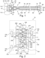
- FIG 2 shows a schematic representation of the first switching device 15 of the Figure 1 shown connector system 10.
- the first switching device 15 has a first switching unit 120 (marked by a dashed rectangle), a second switching unit 155, a first side 125, and a second side 130.
- the first switching unit 120 and the second switching unit 155 are electrically arranged between the first side 125 and the second side 130.
- the first side 125 is connected to the first contact device 25, and the second side 130 is connected to the cable harness 20.
- a sixth number of the first and second switching units 120, 155 corresponds at least to the second number of the first and second contact elements 45, 50 of the first contact device 25.
- a first terminal 135 of the first side 125 is electrically connected to the first contact element 45, and a second terminal 140 of the first side 125 is electrically connected to the second contact element 50.
- a third terminal 145 of the second side 130 can be electrically connected to the first electrical conductor 75, and a fourth terminal 150 of the second side 130 can be electrically connected to the second electrical conductor 80. Contacting of the first side 125 can also be reversed. The first side 125 is thus contacted with the electrical contacts 60, 65 according to the first actual assignment.
- the first switching unit 120 and/or the second switching unit 155 can, for example, comprise an integrated circuit, in particular a field programmable gate array (FPGA), a programmable logic array (PLA), a programmable logic device (PLD), a generic array logic (GAL), and/or a complex programmable logic device (CPLD).
- FPGA field programmable gate array
- PLA programmable logic array
- PLD programmable logic device
- GAL generic array logic
- CPLD complex programmable logic device
- the first switching unit 120 has a first arrangement of two parallel-arranged first and second switching elements 160, 165.
- the first switching unit 120 has at least a seventh number of first and second switching elements 160, 165, which corresponds to the second number of first and second contact elements 45, 50 of the first contact device 25.
- the second switching unit 155 has a second arrangement of at least two parallel arranged third and fourth switching elements 170, 175.
- the second switching unit 155 has at least an eighth number of third and fourth switching elements 170, 175, which correspond to the second number of first and second Contact elements 45, 50 of the first contact device 25.
- the seventh number and the eighth number of first to fourth switching elements 160, 165, 170, 175 are preferably identical.
- the first switching device 15 has a control device 180.
- the switching elements 160, 165, 170, 175 are configured identically to one another.
- the switching element 160, 165, 170, 175 can be configured as an electronic semiconductor component, in particular as a MOSFET.
- the electronic semiconductor component can also be configured differently.
- a first drain terminal 185 of the first switching element 160 is electrically connected to the first terminal 135 via a first connection 190.
- a first node 195 is arranged in the first connection 190, and a second drain terminal 205 of the second switching element 165 is electrically connected to the first node 195 via a second connection 200.
- a first source terminal 210 is electrically connected to the third terminal 145 by means of a third electrical connection 215.
- a second source terminal 220 of the second switching element 165 is connected to the fourth terminal 150 via a fourth connection 225.
- a second node 230 is arranged in the third connection 215 and a third node 235 is arranged in the fourth connection 225.
- the first switching unit 120 has at least a first switching position and a second switching position.
- the control device 180 controls the first switching element 160 via the gate terminal 285 of the first switching element 160 such that the first drain terminal 185 is electrically connected to the first source terminal 210 and the first switching element 160 is switched to the conducting state.
- voltage can be applied to the first gate terminal 285.
- the control device 180 controls the second switching element 165 such that the second switching element 165 is open and the second source terminal 220 is electrically separated from the second drain terminal 205.
- the first terminal 135 is electrically connected to the third terminal 145 via the first connection 190 and the third connection 215.
- the first switching element 160 and the second switching element 165 are reversed to the first switching position by the Control device 180 is switched, wherein the control device 180 controls and closes the second switching element 165 via the gate connection 285, so that the second source connection 220 is electrically connected to the second drain connection 205.
- the first switching element 160 is controlled by the control device 180 such that the first source connection 210 is electrically separated from the first drain connection 185.
- the first connection 135 is connected to the fourth connection 225 and thus to the fourth connection 150 via the first connection 190 and the first node 195 as well as via the second connection 200 and the closed second switching element 165.
- the second switching unit 155 is, by way of example, essentially identical to the first switching unit 120.
- a third source terminal 240 of the third switching element 170 is connected to the second node 230 via a fifth connection 250.
- a fourth source terminal 245 is electrically connected to the second node 230 via a sixth connection 255.
- a third drain terminal 260 of the third switching element 170 is electrically connected to a fourth node 265 via a seventh connection 270.
- the fourth node 265 is arranged in an eighth electrical connection 275, which electrically connects a fourth drain terminal 280 of the fourth switching element 175 to the second terminal 140.
- a gate terminal 285 of each of the switching elements 160, 165, 170, 175 is electrically connected to the control device 180 via a ninth connection 290.
- the second switching unit 155 is configured and switchable essentially analogously to the first switching unit 120.
- the second switching unit 155 has a third switching position and a fourth switching position, wherein in the third switching position, the control device 180 controls and closes the third switching element 170 via the gate terminal 285.
- the third switching position the second terminal 140 is electrically connected to the seventh connection 270 via the eighth connection 275 and the fourth node 265.
- the seventh connection 270 is electrically connected to the fifth connection 250 and the third node 235.
- the second terminal 140 is electrically connected to the fourth terminal 150.
- the control device 180 controls the fourth switching element 175 such that the fourth switching element 175 is open and the fourth source terminal 245 is electrically separated from the fourth drain terminal 280.
- the second switching unit 155 is switched inversely to the third switching position.
- the third switching element 170 is open, and the third drain terminal 260 is electrically isolated from the third source terminal 240.
- the fourth switching element 175 is controlled by the control device 180 at the gate terminal 285 such that the fourth switching element 175 is closed.
- the closed fourth switching element 175 connects the second terminal 140 via the eighth connection 275 to the sixth connection 255 and the second node 230, so that the third terminal 145 is electrically connected to the second terminal 140.
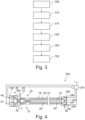
- Figure 3 shows a flow chart of a process for producing the Figures 1 and 2 shown connector system 10.
- Figure 4 shows a schematic representation of a test system 300 with the connector system 10.
- the first contact device 25 is contacted with a first test contact device 291 of the test system 300.
- the first test contact device 291 can be configured identically to the first mating contact device 35.
- the control device 180 is connected to the test device 301 for data purposes.
- the test device 301 uses a continuity test to determine an electrical wiring harness assignment that corresponds to a combination of the first and second actual assignments.
- the first and second switching units 120, 155 are switched by the control device 180 as if the first actual assignment corresponds to the first target assignment and the second actual assignment corresponds to the second target assignment.
- the test device 301 determines that the first mating contact 110 is electrically connected to the fourth mating contact 297 and the second mating contact 115 is electrically connected to the third mating contact 296. For example, if the second contact device 30 were plugged in according to the second nominal assignment, the first mating contact 110 would be electrically connected to the third mating contact 296 by the connector system 10, and the fourth mating contact 297 would be electrically connected to the second mating contact 115 by the connector system 10.
- test device 301 compares the determined actual wiring harness assignment of the connector system 10 with a nominal wiring harness assignment stored in a data memory of the test device 301.
- test device 301 proceeds to a sixth method step 330. If the actual wiring harness configuration corresponds to the nominal wiring harness configuration, the test device 301 outputs information. In this case, the method can be terminated and the test contact devices 291, 295 can be unplugged.
- the test device 301 determines, for example, on the basis of the determined actual wiring harness assignment and the desired wiring harness assignment, a correction switching position of the first to fourth switching elements 160, 165, 170, 175 and provides the determined correction switching position to the control device 180 as a data signal.
- a seventh method step 335 following the sixth method step 330 the control device 180 detects the correction switching position and switches the first to fourth switching elements 160, 165, 170, 175 based on the determined correction switching position and stores the correction switching position.
- the switching of the first to fourth switching elements 160, 165, 170, 175 can be bistable.
- the corrective switching position comprises the switching of the first switching unit 120 into the second switching position and the switching of the second switching unit 155 into the fourth switching position.
- the first and/or second actual assignment and the actual wiring harness assignment are corrected such that the first contact device 25 is assigned the first nominal assignment and the second contact device 30 is assigned the second nominal assignment, even though the second contact device 30 is plugged in incorrectly.
- This configuration has the advantage that the incorrect wiring harness assignment is corrected by the corrective switching position of the first switching device 15, thus avoiding time-consuming troubleshooting or disassembly of an incorrectly assigned wiring harness already installed in the motor vehicle 500.
- the connector system 10 can be connected to the control unit 40 without further rework (see FIG. Figure 1 ) and, for example, connect the control unit 40 to another electrical component 415, for example a consumer 515, for example a window lifter or a headlight.
- Figure 5 shows a schematic representation of a connector system 10 according to a second embodiment.
- the connector system 10 is essentially identical to that shown in the Figures 1 to 4 The following will focus exclusively on the differences between the connector system 10 Figure 5 shown design compared to the one in the Figures 1 to 4 shown design.
- the first switching device 15 is electrically arranged between the first counter-contact device 35 and the control unit 40.
- the first switching device 15 can be part of the control unit 40 and, in particular, can be integrated into the control unit 40.
- the second side 130 is connected to the first counter-contact device 35, and the first side 125 is connected to the control unit 40.
- the third terminal 145 is connected to the first mating contact 110 and the fourth terminal 150 is connected to the second mating contact 115.
- the first contact element 45 is electrically and mechanically connected to the first electrical conductor 75 at an end opposite the third contact element 85
- the second contact element 50 is electrically and mechanically connected to the second contact element 50 at an end opposite the fourth contact element 90.
- the first contact device 25 Due to the possibility of inserting the first contact element 45 into both the first contact receptacle 56 and the second contact receptacle 57, the first contact device 25 has the first actual assignment, which ideally corresponds to the first target assignment, but may also deviate from the first target assignment.
- the incorrect assignment of the connector system 10 can be detected by means of the Figure 3 described method, so that the connector system 10, regardless of whether the first and/or second actual assignment deviates from the respective target assignment, by appropriately switching the first switching device 15 into the first correction switching position, the electrical connector system 10 has the target wiring harness assignment and correct signal transmission and/or power transmission is ensured.
- Figure 6 shows a schematic representation of a connector system 10 according to a third embodiment.
- the connector system 10 is essentially identical to that shown in the Figures 1 to 4 shown connector system 10. Deviating from the shown Figures 1 to 3 In the embodiment shown, the third number of electrical cables 60, 65 in the cable harness 20 is higher than that shown in the Figures 1 and 2 shown design significantly increased. In Figure 6 The nominal assignment of the contact device 25, 30 is shown.
- a correspondingly increased second and fifth number of contact elements 45, 50, 85, 90 is also provided.
- Figure 5 The electrical cables 60, 65 are plugged in according to their intended assignment and thus routed parallel to each other. This prevents kinking of the electrical cables 60, 65 in the cable harness 20. Furthermore, excessive tensile stress on the electrical cables 60, 65 is prevented.
- the first and second The intended assignment of the contact devices 25, 30 is such that crossing of the electrical cables 60, 65 in the cable harness 20 is prevented.
- Figure 7 shows a schematic representation of the Figure 6 shown connector system 10.
- the first switching device 15 has a sixth number of first and second switching units 120, 155 corresponding to the electrical cables 60, 65 of the cable harness 20.
- the terminals 135, 140, 145, 150 were selected in their ninth number corresponding to the sixth number.
- the first side 125 and the second side 130 are Figures 1 to 4 shown design.
- each of the third and fourth terminals 145, 150 can be electrically connected to one of the electrical cables 60, 65.
- the Figure 7 The method described is also applicable accordingly, so that even with a large number of crossed electrical cables 60, 65 and incorrectly plugged contact elements 45, 50, 85, 90, the first and second nominal assignments of the first and second contact devices 25, 30 are established by determining the corrective switching states and corresponding switching of the first switching device 15.
- This embodiment has the advantage that when contacting the contact devices 25, 30 with the contact elements 45, 50, 85, 90, no consideration has to be given to the respective nominal assignment of the contact device 25, 30, but the corresponding first and/or second nominal assignment is established by the corrective switching position of the first switching device 15.
- the first switching device 15 can be part of the cable harness 20, so that the first and second sides 125, 130 are each mechanically and electrically connected to electrical cables 60, 65 of the cable harness 20. This allows both contact devices 25, 30 to be particularly well equipped with contact elements 45, 50, 85, 90.
- Figure 8 shows a schematic representation of a connector system 10 according to a fourth embodiment.
- the connector system 10 is essentially identical to that shown in the Figures 1 to 4 shown connector system 10. In the following, only the differences of the Figure 8 shown connector system 10 compared to the one shown in the Figures 1 to 4 The connector system 10 shown in Figure 1 is discussed. Figure 8 the connection system 10 according to the invention.
- the cable harness 20 additionally has a replacement cable 400 and a second switching device 405.
- the second switching device 405 is electrically arranged between the second contact device 30 and the cable harness 20.
- the second switching device 405 could also be arranged, similar to Figure 5 shown, for example, between a second mating contact device 410 and another electrical component 415, for example, a consumer.
- the second mating contact device 410 mechanically and electrically contacts the second contact device 30 in the assembled state of the connector system 10 in the motor vehicle 500.
- the first switching device 15 is additionally electrically connected to the replacement cable 400 on the second side 130.
- the second switching device 405 is, for example, identical to the first switching device 15 and has, for example, a third side 420 and a fourth side 425.
- the fourth side 425 is electrically connected to the second contact device 30.
- the third side 420 is electrically connected to all electrical cables 60, 65 and to the replacement cable 400 of the cable harness 20.
- the second switching device 405 preferably has at least a third switching unit 430 and a fourth switching unit 435, wherein a tenth number of the provided third and fourth switching units 430, 435 corresponds to the fifth number of the third and fourth contact elements 85, 90 of the second contact device 30 or the second number of the first and second contact elements 45, 50 of the first contact device 25.
- Figure 8 is exemplary, as in the Figures 1 to 4 described, the first and second electrical cables 60, 65 are unintentionally twisted, so that with normal contacting of the contact elements 45, 50, 85, 90 the contact devices 25, 30 are incorrectly assigned and deviate from the first and second nominal assignment of the contact devices 25, 30.
- the first electrical conductor 75 is damaged, so that the first electrical conductor 75 is interrupted and does not allow an electrical connection between the first switching device 15 and the second switching device 405.
- the first electrical conductor 75 can also be damaged in such a way that an ohmic resistance of the first electrical conductor 75 is increased.
- the first switching device 15 and the second switching device 405 are adapted to the increased number of electrical cables 60, 65, 400 in the cable harness 20 compared to the Figures 1 to 4
- the design is adapted such that the seventh and eighth number of first to fourth switching elements 160, 165, 170, 175 corresponds to the third number of electrical cables 60, 65 and a total of 400 spare cables (if more than one spare cable 400 is installed in the cable harness 20).
- the sixth number of first and second switching units 120, 155 corresponds to the second and fifth number of contact elements 45, 50, 85, 90.
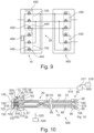
- Figure 9 shows a section of a schematic representation of the Figure 8 shown connector system 10.
- the first and second switching units 120, 155 are each supplemented by an additional fifth and sixth switching element 440, 445 for each replacement cable 400.
- the additional fifth and sixth switching elements 440, 445 are embodied, for example, as MOSFETs and are each connected to the control device 180 at an additional gate terminal 450, for example.
- the third and fourth switching units 430, 435 are also identical to the first and second switching units 120, 155.
- test device 301 not only controls the control device 180 of the first switching device 15, but also the control device 180 of the second switching device 405 in the fourth method step 320 in such a way as if the first Actual occupancy corresponds to the first target occupancy and the second actual occupancy corresponds to the second target occupancy.
- the continuity test of the electrical cables 60, 65 determines which of the electrical conductors 75, 80 of the cable harness 20 is damaged or interrupted.
- the test device 301 can determine, in particular measure, the electrical resistance of each electrical cable 60, 65 of the cable harness 20 as part of the continuity test.
- the replacement cable 400 can also be tested as part of the continuity test, and if necessary, an electrical resistance of the replacement cable 400 can be measured.
- the test device 301 accordingly controls the control device 180 such that the replacement cable 400 is electrically connected to the test device 301 via the contact devices 25, 30 and the switching devices 15, 405.
- the test device 301 compares the determined electrical resistances with a predefined resistance stored in a data memory of the test device 301. If the measured resistance falls below the predefined resistance, the corresponding electrical cable 60, 65 and/or the replacement cable 400 is not damaged. If the measured resistance for the associated electrical cable 60, 65 exceeds the predefined resistance, the electrical cable 60, 65 and/or the replacement cable 400 is damaged.
- the test device 301 takes this into account when determining the corrective switching position.
- the first and second switching devices 15, 405 are switched according to the determined corrective switching position.
- the corrective switching position is determined such that, on the one hand, the contact devices 25, 30 are connected to one another according to the first and second nominal assignments, and, on the other hand, the defective electrical cable 60, 65, for example, the first electrical cable 60, is electrically bridged by the replacement cable 400.
- the first and/or second switching devices 15, 405 may be connected such that the defective first electrical cable 60 is electrically separated from the contact devices 25, 30.
- This configuration has the advantage that no additional cable harness needs to be laid in addition to the connector system 10 described above, in order to ensure redundancy in the motor vehicle 500 in the event of a failure or damage, for example, during assembly of the cable harness 20.
- the damaged first or second electrical cable 60, 65 can be bridged by the replacement cable 400.
- the replacement cable 400 allows the cable harness 20 to remain compact, as the outer diameter of the additional replacement cable 400 of the cable harness 20 only increases slightly.
- the switching device 15, 405 can also be controlled by the test device 301 such that the first and second switching devices 15, 405, the replacement cable 400, are connected in parallel to the first or second electrical cable 60.
- the parallel connection allows a particularly high electrical current to be transmitted through the first or second electrical cable 60, 65 and the replacement cable 400 between the first and second switching devices 15, 405.
- thermal overheating of the first electrical cable 60 and the replacement cable 400 is avoided.
- This embodiment further has the advantage that derating of the cable harness 20, in particular of the first or second electrical cable 60, 65 and the replacement cable 400, is minimized or avoided.
- the corrective switching position is permanently stored by the control unit 180 of the first and second switching devices 15, 405. This allows the corresponding switching of the switching devices 15, 405 to be maintained even after the test system 300 is disconnected from the connector system 10.
- the first switching device 15 and the second switching device 405 are each configured identically to one another. This allows the number of components of the connector system 10 to be kept particularly low.
- the second switching device 405 could also be configured as an arrangement of parallel-arranged diodes, in particular blocking diodes, wherein the diodes have the same orientation relative to one another. This prevents backflow via the bridged first electrical cable 60 from the second switching device 405 to the first switching device 15 through the diodes.
- the first or second switching device 15, 405 can have a first sensor 460, wherein the first sensor 460 provides information about an operating parameter of the connector system 10 to the control device 180.
- the first sensor 460 can be integrated into the first and second switching devices 15, 405.
- the first sensor 460 is, for example, connected to the control device 180 for data purposes and provides, for example, a temperature of the switching device 15, 405 and/or a current transmitted via the switching device 15, 405 as an operating parameter.
- the control device 180 can take the information into account when switching the switching units 120, 155, 430, 435. In particular, for example, in the event of a sharp increase in temperature or current, the control device 180 can connect the replacement cable 400 in parallel with the electrical cable 60, 65 that is preferably the most heated or loaded with electrical current.
- Figure 10 shows a schematic representation of the motor vehicle 500.
- the motor vehicle 500 has a vehicle control unit 505, an electrical consumer 515, an electrical power source 516 and a connector system 10.
- the connector system 10 is exemplary as shown in Figure 5 explained.
- the vehicle control unit 505 is connected for data purposes to the control device 180 of the connector system 10 by means of a tenth connection 510.
- the tenth connection 510 can, for example, be part of a bus system, for example a CAN bus.
- the connector system 10 can, for example, be installed in the motor vehicle 500.
- the connector system 10 is connected to the electrical power source 516 via the first contact device 25 and the first switching device 15, and to the load 30 via the second contact device 30.
- the connector system 10 electrically connects the load 515 to the electrical power source 516 for transmitting electrical power.
- the load 515 can be, for example, a headlight, an electric window lifter, an electric window heater, or a fan motor.
- the electrical power source 516 can be, for example, a 12V, 24V, or 48V electrical supply network of the motor vehicle.
- the vehicle control unit 505 can be connected to a switch 518 for data purposes by means of an eleventh connection 517.
- the switch 518 can be arranged, for example, in the area of the dashboard of the motor vehicle 500, with the Switch 518 detects a request from the driver of the motor vehicle to activate or deactivate the consumer 515.
- the switch 518 provides information about a switching position of the switch 518 to the vehicle control unit 505 by means of a switch signal via the eleventh connection 517.
- the vehicle control unit 505 controls the control device 180 by means of a control signal such that the control device 180 switches the first and second switching units 120, 155 to the corrective switching position for power transmission between the electrical power source 516 and the load 515.
- the first to fourth switching elements 160, 165, 170, 175 are opened. For example, no electrical voltage is applied to the gate terminal 285, 450.
- the load 515 can be a headlight.
- the motor vehicle 500 can further have an additional second sensor 520.
- the second sensor 520 is data-connected to the first switching device 15 via a twelfth connection 525.
- the twelfth connection 525 can, for example, be part of a bus system in the motor vehicle 500.
- the second sensor 520 can be configured, for example, as a brightness sensor. Another configuration of the second sensor 520 is also conceivable. In the embodiment as a brightness sensor, the second sensor 520 provides the information about the detected brightness via the twelfth connection 525 to the first switching device 15.
- the first switching device 15 detects the information provided via the twelfth connection 525.
- the control device 180 takes the provided information into account during operation of the motor vehicle 500. For example, the control device 180 can compare a brightness determined by the sensor 460, 520 with a predefined brightness value stored in the control device 180.
- the control device 180 is designed to control the first and second switching units 120, 155 depending on the determined brightness.
- the control device 180 can switch the first and second switching units 120, 155 when the predefined brightness is exceeded by the determined brightness in such a way that the current transmission between electrical power source 516 and consumer 515 is interrupted. If the determined brightness falls below the predefined brightness, the control device 180 switches the first and second switching units 120, 155 into the correction switching position, so that electrical current is transmitted between the consumer 515, for example the headlight, and the electrical power source 516.
- This configuration has the advantage that the load 515 of the motor vehicle 500, in this embodiment, for example, the headlight, is activated or deactivated autonomously, without control by the vehicle control unit 505. Due to the direct data connection of the second sensor 520 to the first switching device 15 of the connector system 10, the response is particularly fast. Furthermore, this relieves the load on the vehicle control unit 505. In the event of a fault, for example, a fault in the vehicle control unit 505, emergency operation and the switching on of the load 515, for example, the headlight, are still ensured. A data connection of the second sensor 520 to the vehicle control unit 505 is thereby dispensed with.
Landscapes
- Engineering & Computer Science (AREA)
- Mechanical Engineering (AREA)
- Details Of Connecting Devices For Male And Female Coupling (AREA)
Claims (12)
- Système de connexion (10), en particulier système de faisceau de câbles,- le système de connexion (10) comprenant un premier dispositif de commutation (15), un faisceau de câbles (20) ; un premier dispositif de contact (25), un deuxième dispositif de commutation (405) et un deuxième dispositif de contact (30),- le faisceau de câbles (20) comprenant un ensemble d'une pluralité de câbles électriques (60, 65),- un premier câble électrique (60) des câbles électriques (60, 65) étant endommagé ou interrompu,- le premier dispositif de commutation (15) présentant un premier côté (125) et un deuxième côté (130),- l'un des deux côtés (125, 130) étant connecté électriquement au premier dispositif de contact (25),- le faisceau de câbles (20) étant connecté électriquement au premier dispositif de contact (25),- le premier dispositif de commutation (15) étant commuté dans une position de commutation de correction en fonction d'une première affectation souhaitée du premier dispositif de contact (25) ;- le deuxième dispositif de commutation (405) présentant un troisième côté (420) et un quatrième côté (425),- le quatrième côté (425) étant connecté électriquement au deuxième dispositif de contact (30) et le troisième côté (420) étant connecté électriquement au faisceau de câbles (20),- le deuxième dispositif de commutation (405) reliant électriquement le faisceau de câbles (20) au deuxième dispositif de contact (30) en fonction d'une deuxième affectation souhaitée du deuxième dispositif de contact (30) ;
caractérisé en ce que- le faisceau de câbles (20) comporte un câble de remplacement (400),- le câble de remplacement (400) reliant électriquement le premier dispositif de contact (25) au deuxième dispositif de commutation (405),- les premier et deuxième dispositifs de commutation (15, 405) étant commutés dans la position de commutation de correction de telle sorte que le câble de remplacement (400) est connecté électriquement en dérivation par rapport au premier câble électrique (60). - Système de connexion (10) selon la revendication 1,- dans lequel le premier dispositif de commutation (15) est agencé entre le faisceau de câbles (20) et le premier dispositif de contact (25),- le premier côté (125) étant relié électriquement au premier dispositif de contact (25) et le deuxième côté (130) étant relié au faisceau de câbles (20),- le premier dispositif de commutation (15) reliant électriquement le faisceau de câbles (20) au premier dispositif de contact (25) dans la position de commutation de correction et le premier dispositif de contact (25) étant occupé par la première affectation souhaitée.
- Système de connexion (10) selon la revendication 1,- dans lequel le faisceau de câbles (20) est relié électriquement et mécaniquement au premier dispositif de contact (25),- le premier dispositif de contact (25) étant agencé entre le premier dispositif de commutation (15) et le faisceau de câbles (20),- le premier côté (125) étant apte à être relié électriquement à un composant électrique (40) et le deuxième côté (130) étant relié électriquement au premier dispositif de contact (25),- un élément de contact (45, 50) du premier dispositif de contact (25) étant respectivement relié électriquement et mécaniquement à un câble électrique (60, 65) du faisceau de câbles (20),- les éléments de contact (45, 50) du premier dispositif de contact (25) étant agencés avec une première affectation réelle dans un premier boîtier de contact (55),- la position de commutation de correction étant déterminée en fonction de la première affectation réelle et de la première affectation souhaitée.
- Système de connexion (10) selon l'une des revendications précédentes,- dans lequel le premier dispositif de commutation (15) comporte au moins une première unité de commutation (120),- la première unité de commutation (120) étant apte à être commutée au moins entre une première position de commutation et une deuxième position de commutation,- la première unité de commutation (120) reliant électriquement, dans la première position de commutation, une première borne (135) du premier côté (125) à une troisième borne (145) du deuxième côté (130),- la première unité de commutation (120) reliant électriquement, dans la deuxième position de commutation, la première borne (135) à une quatrième borne (150) du deuxième côté (130),- la première unité de commutation (120) étant commutée dans la première position de commutation ou dans la deuxième position de commutation en fonction de la position de commutation de correction du premier dispositif de commutation (15).
- Système de connexion (10) selon la revendication 4,- dans lequel le premier dispositif de commutation (15) comporte au moins une deuxième unité de commutation (155),- la deuxième unité de commutation (155) étant apte à être commutée au moins entre une troisième position de commutation et une quatrième position de commutation,- la deuxième unité de commutation (155) reliant électriquement, dans la troisième position de commutation, une deuxième borne (140) du premier côté (125) à la troisième borne (145) du deuxième côté (130),- la deuxième unité de commutation (155) reliant électriquement, dans la quatrième position de commutation, la deuxième borne (140) à la quatrième borne (150) du deuxième côté (130),- la deuxième unité de commutation (155) étant commutée dans la troisième position de commutation ou dans la quatrième position de commutation en fonction de la position de commutation de correction.
- Système de connexion (10) selon la revendication 4 ou la revendication 5,- dans lequel la première unité de commutation (120) et/ou la deuxième unité de commutation (155) présente un agencement d'au moins deux éléments de commutation (160, 165, 170, 175) agencés en parallèle,- l'élément de commutation (160, 165, 170, 175) comprenant un MOSFET et/ou une diode, en particulier une diode de blocage,
et/ou- l'élément de commutation (160, 165, 170, 175) étant conçu sous la forme d'un composant électronique à semiconducteur (160, 165, 170, 175),- et/ou dans lequel le premier dispositif de commutation (15) présente au moins un circuit intégré, en particulier un réseau de portes programmables par l'utilisateur (Field Programmable Gate Array, FPGA). - Véhicule automobile (500)- présentant un système de connexion (10) selon l'une des revendications précédentes et un appareil de commande de véhicule (505),- l'appareil de commande de véhicule (505) étant relié au premier dispositif de commutation (15) et étant configuré pour commander le premier dispositif de commutation (15).
- Véhicule automobile (500) selon la revendication 7,- dans lequel l'appareil de commande de véhicule (505) est relié à un capteur (460) du système de connexion (10) et est configuré pour détecter une information provenant du capteur (460), concernant un paramètre de fonctionnement du système de connexion (10),- l'appareil de commande du véhicule (505) étant conçu pour prendre en compte le paramètre de fonctionnement lors de la commande du premier dispositif de commutation (15).
- Procédé de fabrication d'un système de connexion (10) selon l'une des revendications 1 à 6,- dans lequel il est réalisé la pose d'un câble électrique (60, 65) d'un faisceau de câbles (20) d'un système de connexion (10),- le faisceau de câbles (20) étant connecté électriquement à un premier dispositif de contact (25) du système de connexion (10),- une position de commutation de correction d'un premier dispositif de commutation (15) étant déterminée en fonction d'une première affectation souhaitée du premier dispositif de contact (25),- le dispositif de commutation (15, 405) étant commuté dans la position de commutation de correction ;- une résistance électrique d'au moins un câble électrique (60, 65), de préférence de tous les câbles électriques (60, 65) du faisceau de câbles (20), étant déterminée,- la résistance électrique étant comparée à une résistance prédéfinie,
caractérisé en ce que- en cas de dépassement de la résistance prédéfinie par la résistance déterminée, la position de commutation de correction est adaptée de telle sorte que le câble électrique (60, 65) dont la résistance électrique dépasse la résistance prédéfinie soit ponté par un câble de remplacement (400). - Procédé selon la revendication 9,- dans lequel on mesure une luminosité, notamment d'un environnement,- la luminosité mesurée étant comparée à une luminosité prédéfinie,- si la luminosité déterminée tombe en dessous de la luminosité prédéfinie, le dispositif de commutation (15) est commuté dans la position de commutation de correction,- dans lequel, en cas de dépassement de la luminosité prédéfinie par la luminosité déterminée, le dispositif de commutation (15) est ouvert et une transmission de courant par le dispositif de commutation (15) est interrompue.
- Procédé selon la revendication 9 ou la revendication 10,- dans lequel un contrôle de continuité est effectué pour chaque câble électrique (60, 65) du faisceau de câbles (20),- une première affectation réelle du dispositif de contact (25, 30) étant déterminée sur la base d'un résultat du contrôle de continuité pour tous les câbles électriques (60, 65),- la première affectation réelle étant prise en compte lors de la détermination de la position de commutation de correction.
- Procédé selon l'une des revendications 9 à 11,- dans lequel une résistance électrique de chaque câble électrique (60, 65) du faisceau de câbles (20) est déterminée,- le câble électrique (60, 65) présentant la plus grande résistance électrique est déterminé,- la position de commutation de correction étant déterminée de telle sorte qu'un câble de remplacement (400) soit connecté en parallèle au câble électrique (60, 65) présentant la plus grande résistance électrique.
Applications Claiming Priority (1)
| Application Number | Priority Date | Filing Date | Title |
|---|---|---|---|
| DE102021103765.4A DE102021103765A1 (de) | 2021-02-17 | 2021-02-17 | Verbindersystem, Kraftfahrzeug und Verfahren zum Betrieb solch eines Verbindersystems |
Publications (2)
| Publication Number | Publication Date |
|---|---|
| EP4046877A1 EP4046877A1 (fr) | 2022-08-24 |
| EP4046877B1 true EP4046877B1 (fr) | 2025-03-26 |
Family
ID=80683228
Family Applications (1)
| Application Number | Title | Priority Date | Filing Date |
|---|---|---|---|
| EP22157241.5A Active EP4046877B1 (fr) | 2021-02-17 | 2022-02-17 | Système de connecteur, véhicule automobile et procédé de fonctionnement d'un tel système de connecteur |
Country Status (2)
| Country | Link |
|---|---|
| EP (1) | EP4046877B1 (fr) |
| DE (1) | DE102021103765A1 (fr) |
Family Cites Families (8)
| Publication number | Priority date | Publication date | Assignee | Title |
|---|---|---|---|---|
| DE7236053U (de) | 1973-03-01 | Hellige F & Co Gmbh | Gerät zur Prüfung von vieladrigen Leitungsverbindungen | |
| DE2609047C3 (de) | 1976-03-05 | 1979-03-22 | Daimler-Benz Ag, 7000 Stuttgart | Vorrichtung zum Prüfen von Kabelsätzen |
| SE9202600L (sv) * | 1992-09-09 | 1993-08-23 | Scarinus Dev Ab | Anordning foer att koda en kabelhaerva |
| US6833713B2 (en) * | 2003-01-31 | 2004-12-21 | Delphi Technologies, Inc. | Smart wire harness for an electrical circuit |
| DE102004010003A1 (de) | 2004-03-01 | 2005-09-29 | Siemens Ag | Automatisierungssystem und Verfahren zur Erkennung und Korrektur von Anschlussfehlern |
| DE202009004988U1 (de) * | 2009-07-03 | 2009-11-12 | Rüttgerodt, Werner | Umprogrammierung eines Anhängererkennungsmoduls |
| JP2013191335A (ja) | 2012-03-13 | 2013-09-26 | Sanpa Kogyo Kk | 多芯ケーブルの芯線接続チェック方法およびその装置 |
| DE102013213597A1 (de) * | 2013-07-11 | 2015-01-29 | Volkswagen Aktiengesellschaft | Verfahren zum Ausrüsten eines Fahrzeugs mit einem Steuergerät |
-
2021
- 2021-02-17 DE DE102021103765.4A patent/DE102021103765A1/de not_active Withdrawn
-
2022
- 2022-02-17 EP EP22157241.5A patent/EP4046877B1/fr active Active
Also Published As
| Publication number | Publication date |
|---|---|
| DE102021103765A1 (de) | 2022-08-18 |
| EP4046877A1 (fr) | 2022-08-24 |
Similar Documents
| Publication | Publication Date | Title |
|---|---|---|
| DE69735639T2 (de) | Elektronisches bussystem | |
| DE69827028T2 (de) | Intelligentes stromverteilungssystem und sein herstellungsverfahren | |
| EP3891021B1 (fr) | Procédé de fabrication pour un réseau de bord d'un véhicule ainsi que réseau de bord de véhicule | |
| DE112017000932B4 (de) | Kabelbaumstruktur | |
| DE102008026737A1 (de) | Kraftfahrzeug-Überstromschutz | |
| EP3338149B1 (fr) | Méthode d'exploitation d'un distributeur de courant et distributeur de courant | |
| DE102016111690A1 (de) | Stromverteiler für ein Fahrzeug | |
| EP1258957B1 (fr) | Ensemble d'interrupteurs | |
| EP3622675B1 (fr) | Connecteur programmable | |
| DE10235788A1 (de) | Elektrisches Verbindungssystem für ein Kraftfahrzeug | |
| EP3539192A1 (fr) | Répartiteur de puissance et réseau de bord comprenant au moins un répartiteur de puissance | |
| EP3884627B1 (fr) | Agencement d'appareil compatible bus muni d'une résistance terminale commutable | |
| DE19826028B4 (de) | Vorrichtung zur Überwachung eines in einem Fahrzeug verwendeten Kabels | |
| EP4046877B1 (fr) | Système de connecteur, véhicule automobile et procédé de fonctionnement d'un tel système de connecteur | |
| DE102013221578A1 (de) | Elektronische Vorrichtung und Verfahren zum Betreiben einer elektronischen Vorrichtung | |
| DE102022209548B3 (de) | Vorrichtung zum Steuern zumindest eines Hochvoltaktuators und Fahrzeug | |
| DE102010038459A1 (de) | Sicherheitssystem | |
| DE102010010845A1 (de) | Elektrischer Steckverbinder | |
| DE102019213254A1 (de) | Steuergerät zur Ansteuerung mindestens eines elektrischen Verbrauchers | |
| DE102015206616A1 (de) | Leiterplatte zur elektronischen Funktionssteuerung für ein Fahrzeug | |
| EP3340200A1 (fr) | Système de détection d'incendie pour un véhicule ferroviaire | |
| DE10213732B4 (de) | Verfahren für die elektrische Versorgung von elektrischen Lasten in einem Fahrzeug | |
| DE102004013486A1 (de) | Fernsteuerzonenverbinder und zugehöriges System | |
| DE10243372B4 (de) | Sicherheitseinrichtung für Leistungsschaltung und Sicherungskasten | |
| DE102019203515A1 (de) | Verfahren zur Energieversorgung von Verbrauchern eines Bordnetzes für ein Fahrzeug sowie ein Bordnetz für ein Fahrzeug |
Legal Events
| Date | Code | Title | Description |
|---|---|---|---|
| PUAI | Public reference made under article 153(3) epc to a published international application that has entered the european phase |
Free format text: ORIGINAL CODE: 0009012 |
|
| STAA | Information on the status of an ep patent application or granted ep patent |
Free format text: STATUS: THE APPLICATION HAS BEEN PUBLISHED |
|
| AK | Designated contracting states |
Kind code of ref document: A1 Designated state(s): AL AT BE BG CH CY CZ DE DK EE ES FI FR GB GR HR HU IE IS IT LI LT LU LV MC MK MT NL NO PL PT RO RS SE SI SK SM TR |
|
| STAA | Information on the status of an ep patent application or granted ep patent |
Free format text: STATUS: REQUEST FOR EXAMINATION WAS MADE |
|
| 17P | Request for examination filed |
Effective date: 20230224 |
|
| RBV | Designated contracting states (corrected) |
Designated state(s): AL AT BE BG CH CY CZ DE DK EE ES FI FR GB GR HR HU IE IS IT LI LT LU LV MC MK MT NL NO PL PT RO RS SE SI SK SM TR |
|
| GRAP | Despatch of communication of intention to grant a patent |
Free format text: ORIGINAL CODE: EPIDOSNIGR1 |
|
| STAA | Information on the status of an ep patent application or granted ep patent |
Free format text: STATUS: GRANT OF PATENT IS INTENDED |
|
| INTG | Intention to grant announced |
Effective date: 20241002 |
|
| GRAS | Grant fee paid |
Free format text: ORIGINAL CODE: EPIDOSNIGR3 |
|
| GRAA | (expected) grant |
Free format text: ORIGINAL CODE: 0009210 |
|
| STAA | Information on the status of an ep patent application or granted ep patent |
Free format text: STATUS: THE PATENT HAS BEEN GRANTED |
|
| AK | Designated contracting states |
Kind code of ref document: B1 Designated state(s): AL AT BE BG CH CY CZ DE DK EE ES FI FR GB GR HR HU IE IS IT LI LT LU LV MC MK MT NL NO PL PT RO RS SE SI SK SM TR |
|
| REG | Reference to a national code |
Ref country code: GB Ref legal event code: FG4D Free format text: NOT ENGLISH |
|
| REG | Reference to a national code |
Ref country code: CH Ref legal event code: EP |
|
| REG | Reference to a national code |
Ref country code: DE Ref legal event code: R096 Ref document number: 502022003292 Country of ref document: DE |
|
| REG | Reference to a national code |
Ref country code: IE Ref legal event code: FG4D Free format text: LANGUAGE OF EP DOCUMENT: GERMAN |
|
| PG25 | Lapsed in a contracting state [announced via postgrant information from national office to epo] |
Ref country code: RS Free format text: LAPSE BECAUSE OF FAILURE TO SUBMIT A TRANSLATION OF THE DESCRIPTION OR TO PAY THE FEE WITHIN THE PRESCRIBED TIME-LIMIT Effective date: 20250626 |
|
| PG25 | Lapsed in a contracting state [announced via postgrant information from national office to epo] |
Ref country code: FI Free format text: LAPSE BECAUSE OF FAILURE TO SUBMIT A TRANSLATION OF THE DESCRIPTION OR TO PAY THE FEE WITHIN THE PRESCRIBED TIME-LIMIT Effective date: 20250326 |
|
| REG | Reference to a national code |
Ref country code: LT Ref legal event code: MG9D |
|
| PG25 | Lapsed in a contracting state [announced via postgrant information from national office to epo] |
Ref country code: NO Free format text: LAPSE BECAUSE OF FAILURE TO SUBMIT A TRANSLATION OF THE DESCRIPTION OR TO PAY THE FEE WITHIN THE PRESCRIBED TIME-LIMIT Effective date: 20250626 |
|
| PG25 | Lapsed in a contracting state [announced via postgrant information from national office to epo] |
Ref country code: HR Free format text: LAPSE BECAUSE OF FAILURE TO SUBMIT A TRANSLATION OF THE DESCRIPTION OR TO PAY THE FEE WITHIN THE PRESCRIBED TIME-LIMIT Effective date: 20250326 |
|
| PG25 | Lapsed in a contracting state [announced via postgrant information from national office to epo] |
Ref country code: LV Free format text: LAPSE BECAUSE OF FAILURE TO SUBMIT A TRANSLATION OF THE DESCRIPTION OR TO PAY THE FEE WITHIN THE PRESCRIBED TIME-LIMIT Effective date: 20250326 |
|
| PG25 | Lapsed in a contracting state [announced via postgrant information from national office to epo] |
Ref country code: GR Free format text: LAPSE BECAUSE OF FAILURE TO SUBMIT A TRANSLATION OF THE DESCRIPTION OR TO PAY THE FEE WITHIN THE PRESCRIBED TIME-LIMIT Effective date: 20250627 Ref country code: BG Free format text: LAPSE BECAUSE OF FAILURE TO SUBMIT A TRANSLATION OF THE DESCRIPTION OR TO PAY THE FEE WITHIN THE PRESCRIBED TIME-LIMIT Effective date: 20250326 |
|
| REG | Reference to a national code |
Ref country code: NL Ref legal event code: MP Effective date: 20250326 |
|
| PG25 | Lapsed in a contracting state [announced via postgrant information from national office to epo] |
Ref country code: NL Free format text: LAPSE BECAUSE OF FAILURE TO SUBMIT A TRANSLATION OF THE DESCRIPTION OR TO PAY THE FEE WITHIN THE PRESCRIBED TIME-LIMIT Effective date: 20250326 |
|
| PG25 | Lapsed in a contracting state [announced via postgrant information from national office to epo] |
Ref country code: SE Free format text: LAPSE BECAUSE OF FAILURE TO SUBMIT A TRANSLATION OF THE DESCRIPTION OR TO PAY THE FEE WITHIN THE PRESCRIBED TIME-LIMIT Effective date: 20250326 |
|
| PG25 | Lapsed in a contracting state [announced via postgrant information from national office to epo] |
Ref country code: SM Free format text: LAPSE BECAUSE OF FAILURE TO SUBMIT A TRANSLATION OF THE DESCRIPTION OR TO PAY THE FEE WITHIN THE PRESCRIBED TIME-LIMIT Effective date: 20250326 |
|
| PG25 | Lapsed in a contracting state [announced via postgrant information from national office to epo] |
Ref country code: ES Free format text: LAPSE BECAUSE OF FAILURE TO SUBMIT A TRANSLATION OF THE DESCRIPTION OR TO PAY THE FEE WITHIN THE PRESCRIBED TIME-LIMIT Effective date: 20250326 Ref country code: PT Free format text: LAPSE BECAUSE OF FAILURE TO SUBMIT A TRANSLATION OF THE DESCRIPTION OR TO PAY THE FEE WITHIN THE PRESCRIBED TIME-LIMIT Effective date: 20250728 |
|
| PG25 | Lapsed in a contracting state [announced via postgrant information from national office to epo] |
Ref country code: PL Free format text: LAPSE BECAUSE OF FAILURE TO SUBMIT A TRANSLATION OF THE DESCRIPTION OR TO PAY THE FEE WITHIN THE PRESCRIBED TIME-LIMIT Effective date: 20250326 Ref country code: IT Free format text: LAPSE BECAUSE OF FAILURE TO SUBMIT A TRANSLATION OF THE DESCRIPTION OR TO PAY THE FEE WITHIN THE PRESCRIBED TIME-LIMIT Effective date: 20250326 |
|
| PG25 | Lapsed in a contracting state [announced via postgrant information from national office to epo] |
Ref country code: EE Free format text: LAPSE BECAUSE OF FAILURE TO SUBMIT A TRANSLATION OF THE DESCRIPTION OR TO PAY THE FEE WITHIN THE PRESCRIBED TIME-LIMIT Effective date: 20250326 |
|
| PG25 | Lapsed in a contracting state [announced via postgrant information from national office to epo] |
Ref country code: RO Free format text: LAPSE BECAUSE OF FAILURE TO SUBMIT A TRANSLATION OF THE DESCRIPTION OR TO PAY THE FEE WITHIN THE PRESCRIBED TIME-LIMIT Effective date: 20250326 |
|
| PG25 | Lapsed in a contracting state [announced via postgrant information from national office to epo] |
Ref country code: SK Free format text: LAPSE BECAUSE OF FAILURE TO SUBMIT A TRANSLATION OF THE DESCRIPTION OR TO PAY THE FEE WITHIN THE PRESCRIBED TIME-LIMIT Effective date: 20250326 |
|
| PG25 | Lapsed in a contracting state [announced via postgrant information from national office to epo] |
Ref country code: IS Free format text: LAPSE BECAUSE OF FAILURE TO SUBMIT A TRANSLATION OF THE DESCRIPTION OR TO PAY THE FEE WITHIN THE PRESCRIBED TIME-LIMIT Effective date: 20250726 |
|
| REG | Reference to a national code |
Ref country code: DE Ref legal event code: R097 Ref document number: 502022003292 Country of ref document: DE |
|
| PG25 | Lapsed in a contracting state [announced via postgrant information from national office to epo] |
Ref country code: DK Free format text: LAPSE BECAUSE OF FAILURE TO SUBMIT A TRANSLATION OF THE DESCRIPTION OR TO PAY THE FEE WITHIN THE PRESCRIBED TIME-LIMIT Effective date: 20250326 |
|
| PG25 | Lapsed in a contracting state [announced via postgrant information from national office to epo] |
Ref country code: CZ Free format text: LAPSE BECAUSE OF FAILURE TO SUBMIT A TRANSLATION OF THE DESCRIPTION OR TO PAY THE FEE WITHIN THE PRESCRIBED TIME-LIMIT Effective date: 20250326 |
|
| PLBE | No opposition filed within time limit |
Free format text: ORIGINAL CODE: 0009261 |
|
| STAA | Information on the status of an ep patent application or granted ep patent |
Free format text: STATUS: NO OPPOSITION FILED WITHIN TIME LIMIT |
|
| REG | Reference to a national code |
Ref country code: CH Ref legal event code: L10 Free format text: ST27 STATUS EVENT CODE: U-0-0-L10-L00 (AS PROVIDED BY THE NATIONAL OFFICE) Effective date: 20260211 |
|
| 26N | No opposition filed |
Effective date: 20260105 |
|
| PGFP | Annual fee paid to national office [announced via postgrant information from national office to epo] |
Ref country code: GB Payment date: 20260219 Year of fee payment: 5 |
|
| PGFP | Annual fee paid to national office [announced via postgrant information from national office to epo] |
Ref country code: DE Payment date: 20260130 Year of fee payment: 5 |
|
| PGFP | Annual fee paid to national office [announced via postgrant information from national office to epo] |
Ref country code: AT Payment date: 20260301 Year of fee payment: 5 |
|
| PGFP | Annual fee paid to national office [announced via postgrant information from national office to epo] |
Ref country code: FR Payment date: 20260223 Year of fee payment: 5 |