EP4046877B1 - Connector system, motor vehicle and method for operating such a connector system - Google Patents
Connector system, motor vehicle and method for operating such a connector system Download PDFInfo
- Publication number
- EP4046877B1 EP4046877B1 EP22157241.5A EP22157241A EP4046877B1 EP 4046877 B1 EP4046877 B1 EP 4046877B1 EP 22157241 A EP22157241 A EP 22157241A EP 4046877 B1 EP4046877 B1 EP 4046877B1
- Authority
- EP
- European Patent Office
- Prior art keywords
- switching
- cable
- contact
- electrical
- connector system
- Prior art date
- Legal status (The legal status is an assumption and is not a legal conclusion. Google has not performed a legal analysis and makes no representation as to the accuracy of the status listed.)
- Active
Links
Images


Classifications
-
- B—PERFORMING OPERATIONS; TRANSPORTING
- B60—VEHICLES IN GENERAL
- B60R—VEHICLES, VEHICLE FITTINGS, OR VEHICLE PARTS, NOT OTHERWISE PROVIDED FOR
- B60R16/00—Electric or fluid circuits specially adapted for vehicles and not otherwise provided for; Arrangement of elements of electric or fluid circuits specially adapted for vehicles and not otherwise provided for
- B60R16/02—Electric or fluid circuits specially adapted for vehicles and not otherwise provided for; Arrangement of elements of electric or fluid circuits specially adapted for vehicles and not otherwise provided for electric constitutive elements
- B60R16/03—Electric or fluid circuits specially adapted for vehicles and not otherwise provided for; Arrangement of elements of electric or fluid circuits specially adapted for vehicles and not otherwise provided for electric constitutive elements for supply of electrical power to vehicle subsystems or for
Definitions
- the invention relates to a connector system according to claim 1, a motor vehicle according to claim 7 and a method according to claim 9.
- Cable harnesses for connecting electrical components in a motor vehicle are known. These cable harnesses have a contact device on both sides, each of which has a predefined assignment. If an error occurs when plugging in the respective contact device, it is only detected during the cable harness inspection. The error cannot be corrected or can only be corrected with great effort.
- EP 2 824 003 A2 shows a method for equipping a vehicle with a control unit.
- an improved connector system can be provided in that the connector system, which is designed in particular as a cable harness system, has a first switching device, a cable harness and a first contact device, wherein the cable harness has an arrangement of a plurality of electrical cables.
- the first switching device has a first side and a second side, wherein one of the two sides is electrically connected to the first contact device.
- the cable harness is connected to the first Contact device directly or indirectly electrically connected.
- the first switching device is switched into a corrective switching position depending on a first desired assignment of the first contact device.
- the connector system has a second switching device and a second contact device, wherein the second switching device has a third side and a fourth side.
- the fourth side is electrically connected to the second contact device and the third side is electrically connected to the cable harness.
- the second switching device electrically connects the cable harness to the second contact device depending on a second desired assignment of the second contact device.
- the cable harness has a spare cable, wherein the spare cable electrically connects the first contact device to the second switching device. The first and second switching devices are switched in such a way that the spare cable electrically bridges the first electrical cable or is connected in parallel to the first electrical cable.
- This design has the advantage that even when the connector system is installed, for example if the first electrical cable is damaged, no additional cable needs to be pulled/installed, but this can be bridged with the replacement cable within the connector system by appropriately switching the two switching devices.
- the design further has the advantage that the cables of the cable harness between the first contact device and the second contact device can be connected to the third side and to the second side depending on their spatial position, and the first switching device and the second switching device establish the desired assignment of the associated contact device. This reduces mechanical stresses in the cable harness and prevents mechanical damage to the electrical conductors of the cable harness.
- the design has the further advantage that a zero-defect cable quota can be ensured for the manufacture of the connector system, since errors in the wiring of the cable harness can be corrected by the corrective switching position of the first switching device.
- the cable harness particularly if the connector system is designed as a cable harness system, can also be designed as a stepped cable harness, so that at least one of the electrical cables is designed as a dead cable/spare cable, which has a function in one of numerous equipment variants of the motor vehicle.
- the non-functional dead cable/spare cable can also be used by the first switching device in a specific equipment variant of the Motor vehicle can be functionally connected, so that the connector system does not have to be manufactured in numerous variants and the number of components in the motor vehicle can be reduced.
- the first switching device is arranged between the cable harness and the first contact device, wherein the first side is electrically connected to the first contact device and the second side is connected to the cable harness.
- the first switching device in the first corrective switching position electrically connects the cable harness to the first contact device, and the first contact device is assigned the first desired assignment.
- the second side can be assigned a first actual assignment of electrical cables of the cable harness.
- the first contact device is arranged between the first switching device and the cable harness.
- the first side can be electrically connected to an electrical component, for example a control unit, and the second side is electrically connected to the first contact device.
- a contact element of the first contact device is electrically and mechanically connected to a respective electrical cable of the cable harness, wherein the contact elements of the first contact device with the first actual assignment are arranged in a first contact housing.
- the corrective switching position is determined as a function of the first actual assignment and the first target assignment.
- the first switching device has at least one first switching unit, wherein the first switching unit is switchable at least between a first switching position and a second switching position. In the first switching position, the first switching unit electrically connects a first terminal of the first side to a third terminal of the second side. In the second switching position, the first switching unit electrically connects the first terminal to a fourth terminal of the second side. The first switching unit is switched to the first switching position or to the second switching position depending on the correction switching position.
- This embodiment has the advantage that the first desired assignment can be established by means of a particularly simply designed switching unit of the first contact device.
- the first switching device can have at least one second switching unit, wherein the second switching unit is switchable at least between a third switching position and a fourth switching position, wherein the second switching unit, in the third switching position, electrically connects a second terminal of the first side to the third terminal of the second side. In the fourth switching position, the second switching unit electrically connects the second terminal to the fourth terminal of the second side. Depending on the correction switching position, the second switching unit is switched to the third switching position or to the fourth switching position.
- This embodiment has the advantage that reverse polarity of the cables in the strand can also be compensated for by the first switching device, so that the first contact device is electrically connected to the electrical cables of the cable harness in accordance with the first desired assignment.
- the first switching unit and/or the second switching unit comprise an arrangement of at least two switching elements arranged in parallel, wherein the switching element comprises a semiconductor component, in particular a transistor, in particular a power transistor, for example a MOSFET, and/or a diode, in particular a blocking diode.
- the switching element comprises a semiconductor component, in particular a transistor, in particular a power transistor, for example a MOSFET, and/or a diode, in particular a blocking diode.
- the switching element is designed as an electronic semiconductor component.
- the first switching device can comprise at least one integrated circuit, in particular a Field Programmable Gate Array (FPGA), Programmable Logic Array (PLA), Programmable Logic Device (PLD), Generic Array Logic (GAL) and/or Complex Programmable Logic Device (CPLD).
- FPGA Field Programmable Gate Array
- PLA Programmable Logic Array
- PLD Programmable Logic Device
- GAL Generic Array Logic
- CPLD Complex Programmable Logic Device
- the parallel connection also prevents thermal overheating of the first electrical cable, for example, in the case of minor damage while simultaneously transmitting high currents.
- a motor vehicle has a connector system and a vehicle control unit, wherein the connector system is designed as described above.
- the vehicle control unit is coupled to the first switching device and designed to control the first switching device.
- the coupling can be achieved, for example, by means of a CAN bus.
- the first switching device can be used, for example, to switch an electrical component connected to the connector system on and off. This eliminates the need for additional control components, in particular relays or semiconductor switching elements, for example MOSFETs, for switching the electrical component on and off. This makes the motor vehicle particularly simple and cost-effective.
- the vehicle control unit is connected to a sensor of the connector system and configured to detect information from the sensor about an operating parameter of the connector system.
- the vehicle control unit is further configured to take the operating parameter into account when controlling the first switching device.
- electrical cables of a cable harness of a connector system are laid, wherein the cable harness is electrically connected to a contact device of the connector system, wherein a corrective switching position of a first switching device of the connector system is determined as a function of a first desired assignment of the first contact device, wherein the first switching device is switched as a function of the determined corrective switching position.
- a brightness of, for example, an environment is measured, wherein the measured brightness is compared with a predefined brightness, wherein if the determined brightness falls below the predefined brightness, the switching device is switched to the correction switching position, wherein if the determined brightness exceeds the predefined brightness, the switching device is opened and current transmission through the switching device is interrupted.
- a continuity test is performed for each electrical cable in the cable harness, and the actual assignment of the contact device is determined based on the result of the continuity test for all electrical cables.
- the first actual assignment is taken into account when determining the corrective switching position. This also allows the corrective switching position to be determined automatically based on the actual assignment and the first target assignment.
- an electrical resistance of at least one electrical cable is determined.
- the electrical resistance of the electrical cable is compared with a predefined resistance. If the determined resistance exceeds the predefined resistance, the correction switch position is adjusted such that the electrical cable whose electrical resistance exceeds the predefined resistance is bypassed by a replacement cable.
- the electrical resistance of each electrical cable in the cable harness is determined, with the electrical cable with the highest electrical resistance being identified.
- the corrective switching position is determined such that a replacement cable is connected in parallel with the cable with the highest electrical resistance.
- connection system 10 In the Figures 1 to 7 the first to third exemplary embodiments of a connection system are explained. These embodiments serve to explain the general structure of the connection system 10, wherein in the Figures 8 and 9 the connection system 10 according to the invention is discussed.
- Figure 1 shows a schematic representation of a connector system 10 according to a first embodiment for a motor vehicle 500.
- the connector system 10 is designed, in particular, as a cable harness system.
- the connector system 10 has a first programmable switching device 15, a cable harness 20, a first contact device 25, and, for example, a second contact device 30.
- the first contact device 25 can directly electrically contact a first mating contact device 35.
- the first mating contact device 35 can be arranged, for example, on a circuit board of a control unit 40.
- the first contact device 25 and the first mating contact device 35 are designed to correspond to one another.
- the first contact device 25 has, for example, a first contact element 45, a second contact element 50, and a first contact housing 55.
- the first contact housing 55 has a first contact receptacle 56 and, for example, a second contact receptacle 57.
- a first number of contact receptacles 56, 57 is essentially limited only by installation space constraints and can be greater than a second number of the first and second contact elements 45, 50.
- first contact receptacle 56 and the second contact receptacle 57 are configured identically to one another.
- first contact element 45 and the second contact element 50 are configured identically to one another, so that the first contact element 45 can be secured in both the first contact receptacle 56 and the second contact receptacle 57.
- the second contact element 50 can be arranged in the first contact receptacle 56 or in the second contact receptacle 57.
- the first contact housing 55 has a first nominal configuration by the first and second contact elements 45, 50.
- the first nominal configuration is such that the first contact element 45 is arranged in the first contact receptacle 56 and the second contact element 50 is arranged in the second contact receptacle 57.
- the cable harness 20 has, for example, a first electrical cable 60 and a second electrical cable 65.
- a third number of electrical cables 60, 65 is freely selectable and can be significantly larger than in Figure 1 be shown.
- the first electrical cable 60 and the second electrical cable 65 are covered by a sheath 70.
- the sheath 70 connects the first electrical cable 60 with the second electrical cable 65 mechanically.
- the sheath 70 can be designed, for example, as a winding.
- the sheath 70 can also comprise a foam material that at least partially accommodates the first electrical cable 60 and the second electrical cable 65. It is particularly advantageous if the first electrical cable 60 and the second electrical cable 65 are embedded in the sheath 70.
- the first electrical cable 60 has a first electrical conductor 75 and a first conductor insulation 76
- the second electrical cable 65 has a second electrical conductor 80 and a second conductor insulation 77.
- the conductor insulation 76, 77 surrounds the respective associated electrical conductor 75, 80 on the circumference and insulates the respective electrical conductor 75, 80 from the other electrical conductor 75, 80.
- the first and second electrical conductors 75, 80 can transmit a data signal and/or electrical power.
- the second contact device 30 has a third contact element 85, a fourth contact element 90, and a second contact housing 95.
- the second contact housing 95 has a third contact receptacle 100 and at least one fourth contact receptacle 105.
- a fourth number of the third and fourth contact receptacles 100, 105 of the second contact housing 95 is essentially limited only by space constraints and can be greater than a fifth number of the contact elements 45, 50 arranged in the second contact housing 95.
- the third contact receptacle 100 and the fourth contact receptacle 105 are configured identically to one another.
- the third contact element 85 and the fourth contact element 90 are configured identically to one another, so that the third contact element 85 can be fastened in both the third contact receptacle 100 and the fourth contact receptacle 105.
- the fourth contact element 90 can be arranged in the third contact receptacle 100 or in the fourth contact receptacle 105.
- the second contact housing 95 has a second nominal configuration by the third and fourth contact elements 85, 90.
- the second nominal configuration is such that the third contact element 85 is arranged in the third contact receptacle 100 and the fourth contact element 90 is arranged in the fourth contact receptacle 105.
- the first and/or second contact receptacle 56, 57 can be configured differently or identically to the third and/or fourth contact receptacle 100, 105.
- the first and/or second contact element 45, 50 can be configured differently or identically to the third and/or fourth contact element 85, 90. It is particularly advantageous if the first and/or second contact element 45, 50 is configured as a plug contact and the third and/or fourth contact element 85, 90 is configured as a socket contact.
- the first electrical conductor 75 is electrically and mechanically connected to the third contact element 85 at one end opposite the first contact element 45.
- the first and third contact elements 45, 85 can each be positively and/or force-fitted to the first electrical conductor 75, for example, crimped and/or pressed and/or soldered.
- the second electrical conductor 80 is electrically and mechanically connected to the fourth contact element 90 at the end opposite the second contact element 50.
- the electrical cables 60, 65 are connected to the first switching device 15 according to a first actual assignment.
- the second contact device 30 Due to the possibility of inserting the third contact element 85 into both the third contact receptacle 100 and the fourth contact receptacle 105, the second contact device 30 has a second actual assignment, which ideally corresponds to the second target assignment, but can also deviate from the second target assignment.
- the second actual assignment differs from the second target assignment.
- the third contact element 85 and the fourth contact element 90 in the second actual assignment are interchanged and inserted into the second contact housing 95.
- the third contact element 85 is arranged in the fourth contact receptacle 105 and the fourth contact element 90 in the third contact receptacle 100.
- This arrangement has the consequence, for example, that, symbolically in Figure 1 shown, the electrical cables 60, 65 of the cable harness 20 cross each other.
- the first mating contact device 35 contacts the first contact device 25 and has a first mating contact 110 and a second mating contact 115.
- the first mating contact 110 can contact the first contact element 45 in the first target configuration or the second contact element 50 in the exemplary first actual configuration.
- FIG 2 shows a schematic representation of the first switching device 15 of the Figure 1 shown connector system 10.
- the first switching device 15 has a first switching unit 120 (marked by a dashed rectangle), a second switching unit 155, a first side 125, and a second side 130.
- the first switching unit 120 and the second switching unit 155 are electrically arranged between the first side 125 and the second side 130.
- the first side 125 is connected to the first contact device 25, and the second side 130 is connected to the cable harness 20.
- a sixth number of the first and second switching units 120, 155 corresponds at least to the second number of the first and second contact elements 45, 50 of the first contact device 25.
- a first terminal 135 of the first side 125 is electrically connected to the first contact element 45, and a second terminal 140 of the first side 125 is electrically connected to the second contact element 50.
- a third terminal 145 of the second side 130 can be electrically connected to the first electrical conductor 75, and a fourth terminal 150 of the second side 130 can be electrically connected to the second electrical conductor 80. Contacting of the first side 125 can also be reversed. The first side 125 is thus contacted with the electrical contacts 60, 65 according to the first actual assignment.
- the first switching unit 120 and/or the second switching unit 155 can, for example, comprise an integrated circuit, in particular a field programmable gate array (FPGA), a programmable logic array (PLA), a programmable logic device (PLD), a generic array logic (GAL), and/or a complex programmable logic device (CPLD).
- FPGA field programmable gate array
- PLA programmable logic array
- PLD programmable logic device
- GAL generic array logic
- CPLD complex programmable logic device
- the first switching unit 120 has a first arrangement of two parallel-arranged first and second switching elements 160, 165.
- the first switching unit 120 has at least a seventh number of first and second switching elements 160, 165, which corresponds to the second number of first and second contact elements 45, 50 of the first contact device 25.
- the second switching unit 155 has a second arrangement of at least two parallel arranged third and fourth switching elements 170, 175.
- the second switching unit 155 has at least an eighth number of third and fourth switching elements 170, 175, which correspond to the second number of first and second Contact elements 45, 50 of the first contact device 25.
- the seventh number and the eighth number of first to fourth switching elements 160, 165, 170, 175 are preferably identical.
- the first switching device 15 has a control device 180.
- the switching elements 160, 165, 170, 175 are configured identically to one another.
- the switching element 160, 165, 170, 175 can be configured as an electronic semiconductor component, in particular as a MOSFET.
- the electronic semiconductor component can also be configured differently.
- a first drain terminal 185 of the first switching element 160 is electrically connected to the first terminal 135 via a first connection 190.
- a first node 195 is arranged in the first connection 190, and a second drain terminal 205 of the second switching element 165 is electrically connected to the first node 195 via a second connection 200.
- a first source terminal 210 is electrically connected to the third terminal 145 by means of a third electrical connection 215.
- a second source terminal 220 of the second switching element 165 is connected to the fourth terminal 150 via a fourth connection 225.
- a second node 230 is arranged in the third connection 215 and a third node 235 is arranged in the fourth connection 225.
- the first switching unit 120 has at least a first switching position and a second switching position.
- the control device 180 controls the first switching element 160 via the gate terminal 285 of the first switching element 160 such that the first drain terminal 185 is electrically connected to the first source terminal 210 and the first switching element 160 is switched to the conducting state.
- voltage can be applied to the first gate terminal 285.
- the control device 180 controls the second switching element 165 such that the second switching element 165 is open and the second source terminal 220 is electrically separated from the second drain terminal 205.
- the first terminal 135 is electrically connected to the third terminal 145 via the first connection 190 and the third connection 215.
- the first switching element 160 and the second switching element 165 are reversed to the first switching position by the Control device 180 is switched, wherein the control device 180 controls and closes the second switching element 165 via the gate connection 285, so that the second source connection 220 is electrically connected to the second drain connection 205.
- the first switching element 160 is controlled by the control device 180 such that the first source connection 210 is electrically separated from the first drain connection 185.
- the first connection 135 is connected to the fourth connection 225 and thus to the fourth connection 150 via the first connection 190 and the first node 195 as well as via the second connection 200 and the closed second switching element 165.
- the second switching unit 155 is, by way of example, essentially identical to the first switching unit 120.
- a third source terminal 240 of the third switching element 170 is connected to the second node 230 via a fifth connection 250.
- a fourth source terminal 245 is electrically connected to the second node 230 via a sixth connection 255.
- a third drain terminal 260 of the third switching element 170 is electrically connected to a fourth node 265 via a seventh connection 270.
- the fourth node 265 is arranged in an eighth electrical connection 275, which electrically connects a fourth drain terminal 280 of the fourth switching element 175 to the second terminal 140.
- a gate terminal 285 of each of the switching elements 160, 165, 170, 175 is electrically connected to the control device 180 via a ninth connection 290.
- the second switching unit 155 is configured and switchable essentially analogously to the first switching unit 120.
- the second switching unit 155 has a third switching position and a fourth switching position, wherein in the third switching position, the control device 180 controls and closes the third switching element 170 via the gate terminal 285.
- the third switching position the second terminal 140 is electrically connected to the seventh connection 270 via the eighth connection 275 and the fourth node 265.
- the seventh connection 270 is electrically connected to the fifth connection 250 and the third node 235.
- the second terminal 140 is electrically connected to the fourth terminal 150.
- the control device 180 controls the fourth switching element 175 such that the fourth switching element 175 is open and the fourth source terminal 245 is electrically separated from the fourth drain terminal 280.
- the second switching unit 155 is switched inversely to the third switching position.
- the third switching element 170 is open, and the third drain terminal 260 is electrically isolated from the third source terminal 240.
- the fourth switching element 175 is controlled by the control device 180 at the gate terminal 285 such that the fourth switching element 175 is closed.
- the closed fourth switching element 175 connects the second terminal 140 via the eighth connection 275 to the sixth connection 255 and the second node 230, so that the third terminal 145 is electrically connected to the second terminal 140.
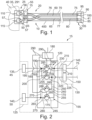
- Figure 3 shows a flow chart of a process for producing the Figures 1 and 2 shown connector system 10.
- Figure 4 shows a schematic representation of a test system 300 with the connector system 10.
- the first contact device 25 is contacted with a first test contact device 291 of the test system 300.
- the first test contact device 291 can be configured identically to the first mating contact device 35.
- the control device 180 is connected to the test device 301 for data purposes.
- the test device 301 uses a continuity test to determine an electrical wiring harness assignment that corresponds to a combination of the first and second actual assignments.
- the first and second switching units 120, 155 are switched by the control device 180 as if the first actual assignment corresponds to the first target assignment and the second actual assignment corresponds to the second target assignment.
- the test device 301 determines that the first mating contact 110 is electrically connected to the fourth mating contact 297 and the second mating contact 115 is electrically connected to the third mating contact 296. For example, if the second contact device 30 were plugged in according to the second nominal assignment, the first mating contact 110 would be electrically connected to the third mating contact 296 by the connector system 10, and the fourth mating contact 297 would be electrically connected to the second mating contact 115 by the connector system 10.
- test device 301 compares the determined actual wiring harness assignment of the connector system 10 with a nominal wiring harness assignment stored in a data memory of the test device 301.
- test device 301 proceeds to a sixth method step 330. If the actual wiring harness configuration corresponds to the nominal wiring harness configuration, the test device 301 outputs information. In this case, the method can be terminated and the test contact devices 291, 295 can be unplugged.
- the test device 301 determines, for example, on the basis of the determined actual wiring harness assignment and the desired wiring harness assignment, a correction switching position of the first to fourth switching elements 160, 165, 170, 175 and provides the determined correction switching position to the control device 180 as a data signal.
- a seventh method step 335 following the sixth method step 330 the control device 180 detects the correction switching position and switches the first to fourth switching elements 160, 165, 170, 175 based on the determined correction switching position and stores the correction switching position.
- the switching of the first to fourth switching elements 160, 165, 170, 175 can be bistable.
- the corrective switching position comprises the switching of the first switching unit 120 into the second switching position and the switching of the second switching unit 155 into the fourth switching position.
- the first and/or second actual assignment and the actual wiring harness assignment are corrected such that the first contact device 25 is assigned the first nominal assignment and the second contact device 30 is assigned the second nominal assignment, even though the second contact device 30 is plugged in incorrectly.
- This configuration has the advantage that the incorrect wiring harness assignment is corrected by the corrective switching position of the first switching device 15, thus avoiding time-consuming troubleshooting or disassembly of an incorrectly assigned wiring harness already installed in the motor vehicle 500.
- the connector system 10 can be connected to the control unit 40 without further rework (see FIG. Figure 1 ) and, for example, connect the control unit 40 to another electrical component 415, for example a consumer 515, for example a window lifter or a headlight.
- Figure 5 shows a schematic representation of a connector system 10 according to a second embodiment.
- the connector system 10 is essentially identical to that shown in the Figures 1 to 4 The following will focus exclusively on the differences between the connector system 10 Figure 5 shown design compared to the one in the Figures 1 to 4 shown design.
- the first switching device 15 is electrically arranged between the first counter-contact device 35 and the control unit 40.
- the first switching device 15 can be part of the control unit 40 and, in particular, can be integrated into the control unit 40.
- the second side 130 is connected to the first counter-contact device 35, and the first side 125 is connected to the control unit 40.
- the third terminal 145 is connected to the first mating contact 110 and the fourth terminal 150 is connected to the second mating contact 115.
- the first contact element 45 is electrically and mechanically connected to the first electrical conductor 75 at an end opposite the third contact element 85
- the second contact element 50 is electrically and mechanically connected to the second contact element 50 at an end opposite the fourth contact element 90.
- the first contact device 25 Due to the possibility of inserting the first contact element 45 into both the first contact receptacle 56 and the second contact receptacle 57, the first contact device 25 has the first actual assignment, which ideally corresponds to the first target assignment, but may also deviate from the first target assignment.
- the incorrect assignment of the connector system 10 can be detected by means of the Figure 3 described method, so that the connector system 10, regardless of whether the first and/or second actual assignment deviates from the respective target assignment, by appropriately switching the first switching device 15 into the first correction switching position, the electrical connector system 10 has the target wiring harness assignment and correct signal transmission and/or power transmission is ensured.
- Figure 6 shows a schematic representation of a connector system 10 according to a third embodiment.
- the connector system 10 is essentially identical to that shown in the Figures 1 to 4 shown connector system 10. Deviating from the shown Figures 1 to 3 In the embodiment shown, the third number of electrical cables 60, 65 in the cable harness 20 is higher than that shown in the Figures 1 and 2 shown design significantly increased. In Figure 6 The nominal assignment of the contact device 25, 30 is shown.
- a correspondingly increased second and fifth number of contact elements 45, 50, 85, 90 is also provided.
- Figure 5 The electrical cables 60, 65 are plugged in according to their intended assignment and thus routed parallel to each other. This prevents kinking of the electrical cables 60, 65 in the cable harness 20. Furthermore, excessive tensile stress on the electrical cables 60, 65 is prevented.
- the first and second The intended assignment of the contact devices 25, 30 is such that crossing of the electrical cables 60, 65 in the cable harness 20 is prevented.
- Figure 7 shows a schematic representation of the Figure 6 shown connector system 10.
- the first switching device 15 has a sixth number of first and second switching units 120, 155 corresponding to the electrical cables 60, 65 of the cable harness 20.
- the terminals 135, 140, 145, 150 were selected in their ninth number corresponding to the sixth number.
- the first side 125 and the second side 130 are Figures 1 to 4 shown design.
- each of the third and fourth terminals 145, 150 can be electrically connected to one of the electrical cables 60, 65.
- the Figure 7 The method described is also applicable accordingly, so that even with a large number of crossed electrical cables 60, 65 and incorrectly plugged contact elements 45, 50, 85, 90, the first and second nominal assignments of the first and second contact devices 25, 30 are established by determining the corrective switching states and corresponding switching of the first switching device 15.
- This embodiment has the advantage that when contacting the contact devices 25, 30 with the contact elements 45, 50, 85, 90, no consideration has to be given to the respective nominal assignment of the contact device 25, 30, but the corresponding first and/or second nominal assignment is established by the corrective switching position of the first switching device 15.
- the first switching device 15 can be part of the cable harness 20, so that the first and second sides 125, 130 are each mechanically and electrically connected to electrical cables 60, 65 of the cable harness 20. This allows both contact devices 25, 30 to be particularly well equipped with contact elements 45, 50, 85, 90.
- Figure 8 shows a schematic representation of a connector system 10 according to a fourth embodiment.
- the connector system 10 is essentially identical to that shown in the Figures 1 to 4 shown connector system 10. In the following, only the differences of the Figure 8 shown connector system 10 compared to the one shown in the Figures 1 to 4 The connector system 10 shown in Figure 1 is discussed. Figure 8 the connection system 10 according to the invention.
- the cable harness 20 additionally has a replacement cable 400 and a second switching device 405.
- the second switching device 405 is electrically arranged between the second contact device 30 and the cable harness 20.
- the second switching device 405 could also be arranged, similar to Figure 5 shown, for example, between a second mating contact device 410 and another electrical component 415, for example, a consumer.
- the second mating contact device 410 mechanically and electrically contacts the second contact device 30 in the assembled state of the connector system 10 in the motor vehicle 500.
- the first switching device 15 is additionally electrically connected to the replacement cable 400 on the second side 130.
- the second switching device 405 is, for example, identical to the first switching device 15 and has, for example, a third side 420 and a fourth side 425.
- the fourth side 425 is electrically connected to the second contact device 30.
- the third side 420 is electrically connected to all electrical cables 60, 65 and to the replacement cable 400 of the cable harness 20.
- the second switching device 405 preferably has at least a third switching unit 430 and a fourth switching unit 435, wherein a tenth number of the provided third and fourth switching units 430, 435 corresponds to the fifth number of the third and fourth contact elements 85, 90 of the second contact device 30 or the second number of the first and second contact elements 45, 50 of the first contact device 25.
- Figure 8 is exemplary, as in the Figures 1 to 4 described, the first and second electrical cables 60, 65 are unintentionally twisted, so that with normal contacting of the contact elements 45, 50, 85, 90 the contact devices 25, 30 are incorrectly assigned and deviate from the first and second nominal assignment of the contact devices 25, 30.
- the first electrical conductor 75 is damaged, so that the first electrical conductor 75 is interrupted and does not allow an electrical connection between the first switching device 15 and the second switching device 405.
- the first electrical conductor 75 can also be damaged in such a way that an ohmic resistance of the first electrical conductor 75 is increased.
- the first switching device 15 and the second switching device 405 are adapted to the increased number of electrical cables 60, 65, 400 in the cable harness 20 compared to the Figures 1 to 4
- the design is adapted such that the seventh and eighth number of first to fourth switching elements 160, 165, 170, 175 corresponds to the third number of electrical cables 60, 65 and a total of 400 spare cables (if more than one spare cable 400 is installed in the cable harness 20).
- the sixth number of first and second switching units 120, 155 corresponds to the second and fifth number of contact elements 45, 50, 85, 90.
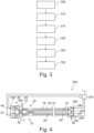
- Figure 9 shows a section of a schematic representation of the Figure 8 shown connector system 10.
- the first and second switching units 120, 155 are each supplemented by an additional fifth and sixth switching element 440, 445 for each replacement cable 400.
- the additional fifth and sixth switching elements 440, 445 are embodied, for example, as MOSFETs and are each connected to the control device 180 at an additional gate terminal 450, for example.
- the third and fourth switching units 430, 435 are also identical to the first and second switching units 120, 155.
- test device 301 not only controls the control device 180 of the first switching device 15, but also the control device 180 of the second switching device 405 in the fourth method step 320 in such a way as if the first Actual occupancy corresponds to the first target occupancy and the second actual occupancy corresponds to the second target occupancy.
- the continuity test of the electrical cables 60, 65 determines which of the electrical conductors 75, 80 of the cable harness 20 is damaged or interrupted.
- the test device 301 can determine, in particular measure, the electrical resistance of each electrical cable 60, 65 of the cable harness 20 as part of the continuity test.
- the replacement cable 400 can also be tested as part of the continuity test, and if necessary, an electrical resistance of the replacement cable 400 can be measured.
- the test device 301 accordingly controls the control device 180 such that the replacement cable 400 is electrically connected to the test device 301 via the contact devices 25, 30 and the switching devices 15, 405.
- the test device 301 compares the determined electrical resistances with a predefined resistance stored in a data memory of the test device 301. If the measured resistance falls below the predefined resistance, the corresponding electrical cable 60, 65 and/or the replacement cable 400 is not damaged. If the measured resistance for the associated electrical cable 60, 65 exceeds the predefined resistance, the electrical cable 60, 65 and/or the replacement cable 400 is damaged.
- the test device 301 takes this into account when determining the corrective switching position.
- the first and second switching devices 15, 405 are switched according to the determined corrective switching position.
- the corrective switching position is determined such that, on the one hand, the contact devices 25, 30 are connected to one another according to the first and second nominal assignments, and, on the other hand, the defective electrical cable 60, 65, for example, the first electrical cable 60, is electrically bridged by the replacement cable 400.
- the first and/or second switching devices 15, 405 may be connected such that the defective first electrical cable 60 is electrically separated from the contact devices 25, 30.
- This configuration has the advantage that no additional cable harness needs to be laid in addition to the connector system 10 described above, in order to ensure redundancy in the motor vehicle 500 in the event of a failure or damage, for example, during assembly of the cable harness 20.
- the damaged first or second electrical cable 60, 65 can be bridged by the replacement cable 400.
- the replacement cable 400 allows the cable harness 20 to remain compact, as the outer diameter of the additional replacement cable 400 of the cable harness 20 only increases slightly.
- the switching device 15, 405 can also be controlled by the test device 301 such that the first and second switching devices 15, 405, the replacement cable 400, are connected in parallel to the first or second electrical cable 60.
- the parallel connection allows a particularly high electrical current to be transmitted through the first or second electrical cable 60, 65 and the replacement cable 400 between the first and second switching devices 15, 405.
- thermal overheating of the first electrical cable 60 and the replacement cable 400 is avoided.
- This embodiment further has the advantage that derating of the cable harness 20, in particular of the first or second electrical cable 60, 65 and the replacement cable 400, is minimized or avoided.
- the corrective switching position is permanently stored by the control unit 180 of the first and second switching devices 15, 405. This allows the corresponding switching of the switching devices 15, 405 to be maintained even after the test system 300 is disconnected from the connector system 10.
- the first switching device 15 and the second switching device 405 are each configured identically to one another. This allows the number of components of the connector system 10 to be kept particularly low.
- the second switching device 405 could also be configured as an arrangement of parallel-arranged diodes, in particular blocking diodes, wherein the diodes have the same orientation relative to one another. This prevents backflow via the bridged first electrical cable 60 from the second switching device 405 to the first switching device 15 through the diodes.
- the first or second switching device 15, 405 can have a first sensor 460, wherein the first sensor 460 provides information about an operating parameter of the connector system 10 to the control device 180.
- the first sensor 460 can be integrated into the first and second switching devices 15, 405.
- the first sensor 460 is, for example, connected to the control device 180 for data purposes and provides, for example, a temperature of the switching device 15, 405 and/or a current transmitted via the switching device 15, 405 as an operating parameter.
- the control device 180 can take the information into account when switching the switching units 120, 155, 430, 435. In particular, for example, in the event of a sharp increase in temperature or current, the control device 180 can connect the replacement cable 400 in parallel with the electrical cable 60, 65 that is preferably the most heated or loaded with electrical current.
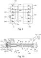
- Figure 10 shows a schematic representation of the motor vehicle 500.
- the motor vehicle 500 has a vehicle control unit 505, an electrical consumer 515, an electrical power source 516 and a connector system 10.
- the connector system 10 is exemplary as shown in Figure 5 explained.
- the vehicle control unit 505 is connected for data purposes to the control device 180 of the connector system 10 by means of a tenth connection 510.
- the tenth connection 510 can, for example, be part of a bus system, for example a CAN bus.
- the connector system 10 can, for example, be installed in the motor vehicle 500.
- the connector system 10 is connected to the electrical power source 516 via the first contact device 25 and the first switching device 15, and to the load 30 via the second contact device 30.
- the connector system 10 electrically connects the load 515 to the electrical power source 516 for transmitting electrical power.
- the load 515 can be, for example, a headlight, an electric window lifter, an electric window heater, or a fan motor.
- the electrical power source 516 can be, for example, a 12V, 24V, or 48V electrical supply network of the motor vehicle.
- the vehicle control unit 505 can be connected to a switch 518 for data purposes by means of an eleventh connection 517.
- the switch 518 can be arranged, for example, in the area of the dashboard of the motor vehicle 500, with the Switch 518 detects a request from the driver of the motor vehicle to activate or deactivate the consumer 515.
- the switch 518 provides information about a switching position of the switch 518 to the vehicle control unit 505 by means of a switch signal via the eleventh connection 517.
- the vehicle control unit 505 controls the control device 180 by means of a control signal such that the control device 180 switches the first and second switching units 120, 155 to the corrective switching position for power transmission between the electrical power source 516 and the load 515.
- the first to fourth switching elements 160, 165, 170, 175 are opened. For example, no electrical voltage is applied to the gate terminal 285, 450.
- the load 515 can be a headlight.
- the motor vehicle 500 can further have an additional second sensor 520.
- the second sensor 520 is data-connected to the first switching device 15 via a twelfth connection 525.
- the twelfth connection 525 can, for example, be part of a bus system in the motor vehicle 500.
- the second sensor 520 can be configured, for example, as a brightness sensor. Another configuration of the second sensor 520 is also conceivable. In the embodiment as a brightness sensor, the second sensor 520 provides the information about the detected brightness via the twelfth connection 525 to the first switching device 15.
- the first switching device 15 detects the information provided via the twelfth connection 525.
- the control device 180 takes the provided information into account during operation of the motor vehicle 500. For example, the control device 180 can compare a brightness determined by the sensor 460, 520 with a predefined brightness value stored in the control device 180.
- the control device 180 is designed to control the first and second switching units 120, 155 depending on the determined brightness.
- the control device 180 can switch the first and second switching units 120, 155 when the predefined brightness is exceeded by the determined brightness in such a way that the current transmission between electrical power source 516 and consumer 515 is interrupted. If the determined brightness falls below the predefined brightness, the control device 180 switches the first and second switching units 120, 155 into the correction switching position, so that electrical current is transmitted between the consumer 515, for example the headlight, and the electrical power source 516.
- This configuration has the advantage that the load 515 of the motor vehicle 500, in this embodiment, for example, the headlight, is activated or deactivated autonomously, without control by the vehicle control unit 505. Due to the direct data connection of the second sensor 520 to the first switching device 15 of the connector system 10, the response is particularly fast. Furthermore, this relieves the load on the vehicle control unit 505. In the event of a fault, for example, a fault in the vehicle control unit 505, emergency operation and the switching on of the load 515, for example, the headlight, are still ensured. A data connection of the second sensor 520 to the vehicle control unit 505 is thereby dispensed with.
Landscapes
- Engineering & Computer Science (AREA)
- Mechanical Engineering (AREA)
- Details Of Connecting Devices For Male And Female Coupling (AREA)
Description
Die Erfindung betrifft ein Verbindersystem gemäß Patentanspruch 1, ein Kraftfahrzeug gemäß Patentanspruch 7 und ein Verfahren gemäß Patentanspruch 9.The invention relates to a connector system according to claim 1, a motor vehicle according to claim 7 and a method according to claim 9.
Es sind Kabelbäume zum Verbinden von elektrischen Komponenten in einem Kraftfahrzeug bekannt. Die Kabelbäume weisen beidseitig eine Kontakteinrichtung auf, wobei die Kontakteinrichtung jeweils eine vordefinierte Sollbelegung aufweist. Tritt beim Stecken der jeweiligen Kontakteinrichtung ein Fehler auf, so wird dieser erst bei der Überprüfung der Kabelbäume festgestellt. Der Fehler kann nicht oder nur aufwendig behoben werden.Cable harnesses for connecting electrical components in a motor vehicle are known. These cable harnesses have a contact device on both sides, each of which has a predefined assignment. If an error occurs when plugging in the respective contact device, it is only detected during the cable harness inspection. The error cannot be corrected or can only be corrected with great effort.
Aus
Des Weiteren zeigt das gattungsgemäße
Es ist Aufgabe der Erfindung, ein verbessertes Verbindersystem, insbesondere einen verbesserten Kabelbaum, ein verbessertes Kraftfahrzeug und ein verbessertes Verfahren zum Betrieb solch eines Verbindersystems bereitzustellen.It is an object of the invention to provide an improved connector system, in particular an improved wiring harness, an improved motor vehicle and an improved method for operating such a connector system.
Diese Aufgabe wird mittels der Merkmale der Hauptansprüche gelöst. Vorteilhafte Ausführungsformen sind in den abhängigen Ansprüchen angegeben.This object is achieved by means of the features of the main claims. Advantageous embodiments are specified in the dependent claims.
Erfindungsgemäß wurde erkannt, dass ein verbessertes Verbindersystem dadurch bereitgestellt werden kann, dass das Verbindersystem, das insbesondere als Kabelbaumsystem ausgebildet ist, eine erste Schalteinrichtung, einen Kabelstrang und eine erste Kontakteinrichtung aufweist, wobei der Kabelstrang eine Anordnung aus einer Vielzahl von elektrischen Kabeln aufweist. Die erste Schalteinrichtung weist eine erste Seite und eine zweite Seite auf, wobei eine der beiden Seiten mit der ersten Kontakteinrichtung elektrisch verbunden ist. Der Kabelstrang ist mit der ersten Kontakteinrichtung direkt oder indirekt elektrisch verbunden. Die erste Schalteinrichtung ist in Abhängigkeit einer ersten Sollbelegung der ersten Kontakteinrichtung in eine Korrekturschaltstellung geschalten. Das Verbindersystem weist eine zweite Schalteinrichtung und eine zweite Kontakteinrichtung auf, wobei die zweite Schalteinrichtung eine dritte Seite und eine vierte Seite aufweist. Die vierte Seite ist mit der zweiten Kontakteinrichtung und die dritte Seite ist mit dem Kabelstrang elektrisch verbunden. Die zweite Schalteinrichtung verbindet in Abhängigkeit einer zweiten Sollbelegung der zweiten Kontakteinrichtung den Kabelstrang mit der zweiten Kontakteinrichtung elektrisch. Der Kabelstrang weist ein Ersatzkabel auf, wobei das Ersatzkabel die erste Kontakteinrichtung mit der zweiten Schalteinrichtung elektrisch verbindet. Die erste und zweite Schalteinrichtung sind derart geschalten, dass das Ersatzkabel das erste elektrische Kabel elektrisch überbrückt oder parallel zu dem ersten elektrischen Kabel geschalten wird.According to the invention, it was recognized that an improved connector system can be provided in that the connector system, which is designed in particular as a cable harness system, has a first switching device, a cable harness and a first contact device, wherein the cable harness has an arrangement of a plurality of electrical cables. The first switching device has a first side and a second side, wherein one of the two sides is electrically connected to the first contact device. The cable harness is connected to the first Contact device directly or indirectly electrically connected. The first switching device is switched into a corrective switching position depending on a first desired assignment of the first contact device. The connector system has a second switching device and a second contact device, wherein the second switching device has a third side and a fourth side. The fourth side is electrically connected to the second contact device and the third side is electrically connected to the cable harness. The second switching device electrically connects the cable harness to the second contact device depending on a second desired assignment of the second contact device. The cable harness has a spare cable, wherein the spare cable electrically connects the first contact device to the second switching device. The first and second switching devices are switched in such a way that the spare cable electrically bridges the first electrical cable or is connected in parallel to the first electrical cable.
Diese Ausgestaltung hat den Vorteil, dass auch in verlegtem Zustand des Verbindersystems, beispielsweise wenn das erste elektrische Kabel beschädigt ist, kein zusätzliches Kabel gezogen/verlegt werden muss, sondern dieses mit dem Ersatzkabel innerhalb des Verbindersystems durch entsprechende Schaltung der beiden Schalteinrichtungen überbrückt werden kann.This design has the advantage that even when the connector system is installed, for example if the first electrical cable is damaged, no additional cable needs to be pulled/installed, but this can be bridged with the replacement cable within the connector system by appropriately switching the two switching devices.
Die Ausgestaltung hat ferner den Vorteil, dass die Kabel des Kabelstrangs zwischen der ersten Kontakteinrichtung und der zweiten Kontakteinrichtung in Abhängigkeit ihrer räumlichen Lage mit der dritten Seite und mit der zweiten Seite verbunden werden können und durch die erste Schalteinrichtung und die zweite Schalteinrichtung jeweils die Sollbelegung der zugeordneten Kontakteinrichtung hergestellt wird. Dadurch werden mechanische Spannungen im Kabelstrang reduziert und dadurch eine mechanische Beschädigung elektrischer Leiter des Kabelstrangs verhindert.The design further has the advantage that the cables of the cable harness between the first contact device and the second contact device can be connected to the third side and to the second side depending on their spatial position, and the first switching device and the second switching device establish the desired assignment of the associated contact device. This reduces mechanical stresses in the cable harness and prevents mechanical damage to the electrical conductors of the cable harness.
Die Ausgestaltung hat den weiteren Vorteil, dass eine Nullfehlerkabelquote für die Herstellung des Verbindersystems sichergestellt werden kann, da Fehler bei der Verkabelung des Kabelstrangs durch die Korrekturschaltstellung der ersten Schalteinrichtung korrigiert werden können. Ferner kann der Kabelstrang, insbesondere wenn das Verbindersystem als Kabelbaumsystem ausgebildet ist, auch als Stufenkabelbaum ausgebildet sein, sodass wenigstens eines der elektrischen Kabel als Totkabel/Ersatzkabel ausgebildet ist, das bei einer von zahlreichen Ausstattungsvarianten des Kraftfahrzeugs eine Funktion aufweist. Das funktionslose Totkabel/Ersatzkabel kann durch die erste Schalteinrichtung auch in einer bestimmten Ausstattungsvariante des Kraftfahrzeugs funktionsbehaftet geschalten werden, sodass das Verbindersystem nicht in zahlreichen Varianten hergestellt werden muss und eine Bauteilvielzahl im Kraftfahrzeug reduziert werden kann.The design has the further advantage that a zero-defect cable quota can be ensured for the manufacture of the connector system, since errors in the wiring of the cable harness can be corrected by the corrective switching position of the first switching device. Furthermore, the cable harness, particularly if the connector system is designed as a cable harness system, can also be designed as a stepped cable harness, so that at least one of the electrical cables is designed as a dead cable/spare cable, which has a function in one of numerous equipment variants of the motor vehicle. The non-functional dead cable/spare cable can also be used by the first switching device in a specific equipment variant of the Motor vehicle can be functionally connected, so that the connector system does not have to be manufactured in numerous variants and the number of components in the motor vehicle can be reduced.
In einer weiteren Ausführungsform ist die erste Schalteinrichtung zwischen dem Kabelstrang und der ersten Kontakteinrichtung angeordnet, wobei die erste Seite elektrisch mit der ersten Kontakteinrichtung und die zweite Seite mit dem Kabelstrang verbunden ist. Die erste Schalteinrichtung in der ersten Korrekturschaltstellung verbindet den Kabelstrang elektrisch mit der ersten Kontakteinrichtung und die erste Kontakteinrichtung ist mit der ersten Sollbelegung belegt. Dabei kann die zweite Seite mit einer ersten Istbelegung von elektrischen Kabeln des Kabelstrangs belegt sein. Diese Ausgestaltung hat den Vorteil, dass das Verbindersystem als kompaktes Kabelbaumsystem bereitgestellt wird, das zusammen mit der bereits programmierten und geschalteten ersten Schalteinrichtung ausgeliefert werden kann. Dadurch kann das Verbindersystem direkt im Kraftahrzeug montiert werden, ohne dass weitere Testroutinen und Einstellungsroutinen im Werk des Fahrzeugherstellers notwendig sind. Durch die Korrekturschaltstellung der ersten Schalteinrichtung wird die erste Istbelegung der zweiten Seite auf die erste Sollbelegung der ersten Kontakteinrichtung umgeschaltet. Dadurch kann die zweite Seite unabhängig und besonders schnell montiert werden.In a further embodiment, the first switching device is arranged between the cable harness and the first contact device, wherein the first side is electrically connected to the first contact device and the second side is connected to the cable harness. The first switching device in the first corrective switching position electrically connects the cable harness to the first contact device, and the first contact device is assigned the first desired assignment. The second side can be assigned a first actual assignment of electrical cables of the cable harness. This configuration has the advantage that the connector system is provided as a compact wiring harness system that can be delivered together with the already programmed and switched first switching device. This allows the connector system to be installed directly in the motor vehicle without the need for further test routines and adjustment routines at the vehicle manufacturer's factory. The corrective switching position of the first switching device switches the first actual assignment of the second side to the first desired assignment of the first contact device. This allows the second side to be installed independently and particularly quickly.
In einer weiteren Ausführungsform ist die erste Kontakteinrichtung zwischen der ersten Schalteinrichtung und dem Kabelstrang angeordnet. Die erste Seite ist mit einer elektrischen Komponente, beispielsweise einem Steuergerät, elektrisch verbindbar und die zweite Seite ist mit der ersten Kontakteinrichtung elektrisch verbunden. Jeweils ein Kontaktelement der ersten Kontakteinrichtung ist mit jeweils einem elektrischen Kabel des Kabelstrangs elektrisch und mechanisch verbunden, wobei die Kontaktelemente der ersten Kontakteinrichtung mit der ersten Istbelegung in einem ersten Kontaktgehäuse angeordnet sind. Die Korrekturschaltstellung ist in Abhängigkeit der ersten Istbelegung und der ersten Sollbelegung bestimmt. Diese Ausgestaltung hat den Vorteil, dass durch die direkte Verbindung des Kabelstrangs mit der ersten Kontakteinrichtung der Kabelstrang direkt anschließend an die erste Kontakteinrichtung in einem engen Radius geführt werden kann, ohne dass hierbei die erste Schalteinrichtung mechanisch beschädigt wird. Ferner kann die erste Kontakteinrichtung besonders schnell, vorzugsweise automatisiert, und unabhängig von der ersten Sollbelegung bestückt werden.In a further embodiment, the first contact device is arranged between the first switching device and the cable harness. The first side can be electrically connected to an electrical component, for example a control unit, and the second side is electrically connected to the first contact device. In each case, a contact element of the first contact device is electrically and mechanically connected to a respective electrical cable of the cable harness, wherein the contact elements of the first contact device with the first actual assignment are arranged in a first contact housing. The corrective switching position is determined as a function of the first actual assignment and the first target assignment. This embodiment has the advantage that, due to the direct connection of the cable harness to the first contact device, the cable harness can be routed directly adjacent to the first contact device in a tight radius without causing mechanical damage to the first switching device. Furthermore, the first contact device can be equipped particularly quickly, preferably automatically, and independently of the first target assignment.
In einer weiteren Ausführungsform weist die erste Schalteinrichtung wenigstens eine erste Schalteinheit auf, wobei die erste Schalteinheit zumindest zwischen einer ersten Schaltstellung und einer zweiten Schaltstellung schaltbar ist. Die erste Schalteinheit verbindet elektrisch in der ersten Schaltstellung einen ersten Anschluss der ersten Seite mit einem dritten Anschluss der zweiten Seite. In der zweiten Schaltstellung verbindet die erste Schalteinheit den ersten Anschluss mit einem vierten Anschluss der zweiten Seite elektrisch. Die erste Schalteinheit ist in die erste Schaltstellung oder in die zweite Schaltstellung in Abhängigkeit der Korrekturschaltstellung geschaltet. Diese Ausgestaltung hat den Vorteil, dass die erste Sollbelegung mittels einer besonders einfach ausgebildeten Schalteinheit der ersten Kontakteinrichtung hergestellt werden kann.In a further embodiment, the first switching device has at least one first switching unit, wherein the first switching unit is switchable at least between a first switching position and a second switching position. In the first switching position, the first switching unit electrically connects a first terminal of the first side to a third terminal of the second side. In the second switching position, the first switching unit electrically connects the first terminal to a fourth terminal of the second side. The first switching unit is switched to the first switching position or to the second switching position depending on the correction switching position. This embodiment has the advantage that the first desired assignment can be established by means of a particularly simply designed switching unit of the first contact device.
In einer weiteren Ausführungsform kann die erste Schalteinrichtung wenigstens eine zweite Schalteinheit aufweisen, wobei die zweite Schalteinheit zumindest zwischen einer dritten Schaltstellung und einer vierten Schaltstellung schaltbar ist, wobei die zweite Schalteinheit in der dritten Schaltstellung einen zweiten Anschluss der ersten Seite mit dem dritten Anschluss der zweiten Seite elektrisch verbindet. Die zweite Schalteinheit verbindet elektrisch in der vierten Schaltstellung den zweiten Anschluss mit dem vierten Anschluss der zweiten Seite. In Abhängigkeit der Korrekturschaltstellung ist die zweite Schalteinheit in die dritte Schaltstellung oder in die vierte Schaltstellung geschalten. Diese Ausgestaltung hat den Vorteil, dass auch eine Verpolung der Kabel im Strang durch die erste Schalteinrichtung ausgeglichen werden kann, sodass die erste Kontakteinrichtung entsprechend der ersten Sollbelegung mit den elektrischen Kabeln des Kabelstrangs elektrisch verbunden ist.In a further embodiment, the first switching device can have at least one second switching unit, wherein the second switching unit is switchable at least between a third switching position and a fourth switching position, wherein the second switching unit, in the third switching position, electrically connects a second terminal of the first side to the third terminal of the second side. In the fourth switching position, the second switching unit electrically connects the second terminal to the fourth terminal of the second side. Depending on the correction switching position, the second switching unit is switched to the third switching position or to the fourth switching position. This embodiment has the advantage that reverse polarity of the cables in the strand can also be compensated for by the first switching device, so that the first contact device is electrically connected to the electrical cables of the cable harness in accordance with the first desired assignment.
In einer weiteren Ausführungsform weist die erste Schalteinheit und/oder die zweite Schalteinheit eine Anordnung aus wenigstens zwei parallel angeordneten Schaltelementen auf, wobei das Schaltelement, ein Halbleiterbauelement, insbesondere einen Transistor, insbesondere ein Leistungstransistor, beispielsweise einen MOSFET und/oder eine Diode, insbesondere eine Sperrdiode, aufweist. Diese Ausgestaltung hat den Vorteil, dass die Schalteinheit besonders kostengünstig aus Standardbauteilen hergestellt werden kann und kompakt in dem Verbindersystem integriert werden kann.In a further embodiment, the first switching unit and/or the second switching unit comprise an arrangement of at least two switching elements arranged in parallel, wherein the switching element comprises a semiconductor component, in particular a transistor, in particular a power transistor, for example a MOSFET, and/or a diode, in particular a blocking diode. This configuration has the advantage that the switching unit can be manufactured particularly cost-effectively from standard components and can be compactly integrated into the connector system.
Zusätzlich oder alternativ ist das Schaltelement als elektronisches Halbleiter-Bauelement ausgebildet. Zusätzlich oder alternativ kann die erste Schalteinrichtung wenigstens einen integrierten Schaltkreis, insbesondere ein Field Programmable Gate Array (FPGA), Programmable Logic Array (PLA), Programmable Logic Device (PLD), Generic Array Logic (GAL) und/oder Complex Programmable Logic Device (CPLD), aufweisen. Diese Ausgestaltung eignet sich für einen Kabelstrang mit einer Vielzahl von elektrischen Kabeln, da bei diesem durch die erste Schalteinrichtung die Sollbelegung der ersten Kontakteinrichtung auch bei einer völlig falschen erster Istbelegung hergestellt werden kann.Additionally or alternatively, the switching element is designed as an electronic semiconductor component. Additionally or alternatively, the first switching device can comprise at least one integrated circuit, in particular a Field Programmable Gate Array (FPGA), Programmable Logic Array (PLA), Programmable Logic Device (PLD), Generic Array Logic (GAL) and/or Complex Programmable Logic Device (CPLD). This design is suitable for a cable harness with a large number of electrical cables, since the first switching device can establish the desired assignment of the first contact device even if the first actual assignment is completely incorrect.
Dadurch ist der Aufwand für eine Nachbearbeitung besonders gering. Auch kann durch die Parallelschaltung eine thermische Überhitzung des ersten elektrischen Kabels, beispielsweise bei einem geringen Schaden und gleichzeitig hohen zu übertragenden Strömen, vermieden werden.This minimizes the effort required for post-processing. The parallel connection also prevents thermal overheating of the first electrical cable, for example, in the case of minor damage while simultaneously transmitting high currents.
Ein Kraftfahrzeug weist ein Verbindersystem und ein Fahrzeugsteuergerät auf, wobei das Verbindersystem wie oben beschrieben ausgebildet ist. Das Fahrzeugsteuergerät ist mit der ersten Schalteinrichtung gekoppelt und ausgebildet, die erste Schalteinrichtung zu steuern. Die Kopplung kann beispielsweise mittels eines CAN-Busses erzielt werden. Durch die Kopplung des Fahrzeugsteuergeräts mit der Schalteinrichtung kann die erste Schalteinrichtung genutzt werden, um beispielsweise eine an dem Verbindersystem angeschlossene elektrische Komponente ein- und auszuschalten. Dadurch kann auf zusätzliche Steuerkomponenten, insbesondere Relais oder Halbleiterschaltelemente, beispielsweise MOSFETs, zum Ein- und Ausschalten der elektrischen Komponente verzichtet werden. Dadurch ist das Kraftfahrzeug besonders einfach und kostengünstig ausgebildet.A motor vehicle has a connector system and a vehicle control unit, wherein the connector system is designed as described above. The vehicle control unit is coupled to the first switching device and designed to control the first switching device. The coupling can be achieved, for example, by means of a CAN bus. By coupling the vehicle control unit to the switching device, the first switching device can be used, for example, to switch an electrical component connected to the connector system on and off. This eliminates the need for additional control components, in particular relays or semiconductor switching elements, for example MOSFETs, for switching the electrical component on and off. This makes the motor vehicle particularly simple and cost-effective.
In einer weiteren Ausführungsform ist das Fahrzeugsteuergerät mit einem Sensor des Verbindersystems verbunden und ausgebildet, eine Information des Sensors über einen Betriebsparameter des Verbindersystems zu erfassen. Das Fahrzeugsteuergerät ist weiter ausgebildet, den Betriebsparameter bei der Steuerung der ersten Schalteinrichtung zu berücksichtigen.In a further embodiment, the vehicle control unit is connected to a sensor of the connector system and configured to detect information from the sensor about an operating parameter of the connector system. The vehicle control unit is further configured to take the operating parameter into account when controlling the first switching device.
In einem Verfahren werden elektrische Kabel eines Kabelstrangs eines Verbindersystems verlegt, wobei der Kabelstrang mit einer Kontakteinrichtung des Verbindersystems elektrisch verbunden wird, wobei eine Korrekturschaltstellung einer ersten Schalteinrichtung des Verbindersystems in Abhängigkeit einer ersten Sollbelegung der ersten Kontakteinrichtung ermittelt wird, wobei die erste Schalteinrichtung in Abhängigkeit der ermittelten Korrekturschaltstellung geschalten wird.In a method, electrical cables of a cable harness of a connector system are laid, wherein the cable harness is electrically connected to a contact device of the connector system, wherein a corrective switching position of a first switching device of the connector system is determined as a function of a first desired assignment of the first contact device, wherein the first switching device is switched as a function of the determined corrective switching position.
In einer weiteren Ausführungsform wird eine Helligkeit beispielsweise einer Umgebung gemessen, wobei die gemessene Helligkeit mit einer vordefinierten Helligkeit verglichen wird, wobei bei Unterschreiten der vordefinierten Helligkeit durch die ermittelte Helligkeit die Schalteinrichtung in die Korrekturschaltstellung geschalten wird, wobei bei Überschreiten der vordefinierten Helligkeit durch die ermittelte Helligkeit die Schalteinrichtung geöffnet wird und eine Stromübertragung durch die Schalteinrichtung unterbrochen ist. Dadurch kann auf weitere Schalter verzichtet werden und beispielsweise Scheinwerfer mit dem Verbindersystem, insbesondere mittels des Kabelbaumsystems, geschalten werden. Auch durch die Integration kann beispielsweise auf ein Lichtmodul verzichtet werden und/oder eine Reaktionszeit bis zur Aktivierung bzw. Deaktiverung der Stromübertragung besonders kurz gehalten werden.In a further embodiment, a brightness of, for example, an environment is measured, wherein the measured brightness is compared with a predefined brightness, wherein if the determined brightness falls below the predefined brightness, the switching device is switched to the correction switching position, wherein if the determined brightness exceeds the predefined brightness, the switching device is opened and current transmission through the switching device is interrupted. This makes it possible to dispense with additional switches and, for example, to switch headlights using the connector system, in particular by means of the cable harness system. The integration also makes it possible, for example, to dispense with a light module and/or to keep the reaction time until the current transmission is activated or deactivated particularly short.
In einer weiteren Ausführungsform wird eine Durchgangsprüfung für jedes elektrische Kabel des Kabelstrangs durchgeführt, wobei auf Grundlage eines Ergebnisses der Durchgangsprüfung für alle elektrischen Kabel die Istbelegung der Kontakteinrichtung ermittelt wird. Die erste Istbelegung wird bei Ermittlung der Korrekturschaltstellung berücksichtigt. Dadurch kann auch automatisiert die Korrekturschaltstellung auf Grundlage der Istbelegung und der ersten Sollbelegung ermittelt werden.In a further embodiment, a continuity test is performed for each electrical cable in the cable harness, and the actual assignment of the contact device is determined based on the result of the continuity test for all electrical cables. The first actual assignment is taken into account when determining the corrective switching position. This also allows the corrective switching position to be determined automatically based on the actual assignment and the first target assignment.
In einer weiteren Ausführungsform wird ein elektrischer Widerstand wenigstens eines elektrischen Kabels, vorzugsweise aller elektrischen Kabel des Kabelstrangs ermittelt, wobei der elektrische Widerstand des elektrischen Kabels mit einem vordefinierten Widerstand verglichen wird, wobei bei Überschreiten des vordefinierten Widerstands durch den ermittelten Widerstand die Korrekturschaltstellung derart angepasst wird, dass das elektrische Kabel, dessen elektrischer Widerstand den vordefinierten Widerstand überschreitet, durch ein Ersatzkabel überbrückt wird. Diese Ausgestaltung hat den Vorteil, dass ein Kabelbrand durch Deaktivierung und Überbrückung des gefährdeten Kabels vermieden werden kann.In a further embodiment, an electrical resistance of at least one electrical cable, preferably of all electrical cables in the cable harness, is determined. The electrical resistance of the electrical cable is compared with a predefined resistance. If the determined resistance exceeds the predefined resistance, the correction switch position is adjusted such that the electrical cable whose electrical resistance exceeds the predefined resistance is bypassed by a replacement cable. This embodiment has the advantage that a cable fire can be prevented by deactivating and bypassing the endangered cable.
In einer weiteren Ausführungsform wird ein elektrischer Widerstand jedes elektrischen Kabels des Kabelstrangs ermittelt, wobei das elektrische Kabel mit dem größten elektrischen Widerstand bestimmt wird, wobei die Korrekturschaltstellung derart bestimmt wird, dass ein Ersatzkabel parallel zu dem Kabel mit dem größten elektrischen Widerstand geschalten wird. Diese Ausgestaltung hat den Vorteil, dass eine thermische Belastung des elektrischen Kabels durch Parallelschaltung des Ersatzkabels reduziert werden kann und ein Kabelbrand vermieden werden kann.In a further embodiment, the electrical resistance of each electrical cable in the cable harness is determined, with the electrical cable with the highest electrical resistance being identified. The corrective switching position is determined such that a replacement cable is connected in parallel with the cable with the highest electrical resistance. This embodiment has the advantage that thermal stress on the electrical cable can be reduced by connecting the replacement cable in parallel, and a cable fire can be prevented.
Nachfolgend wird die Erfindung anhand von Figuren näher erläutert. Dabei zeigen:
- Figur 1
- eine schematische Darstellung eines Verbindersystems gemäß einer ersten Ausführungsform für ein Kraftfahrzeug;
- Figur 2
- eine schematische Darstellung einer ersten Schalteinrichtung des in
Figur 1 gezeigten Verbindersystems; - Figur 3
- ein Ablaufdiagramm eines Verfahrens zur Herstellung des in den
Figuren 1 und 2 gezeigten Verbindersystems; - Figur 4
- eine schematische Darstellung eines Testsystems mit dem Verbindersystem;
- Figur 5
- eine schematische Darstellung eines Verbindersystems gemäß einer zweiten Ausführungsform;
- Figur 6
- eine schematische Darstellung eines Verbindersystems gemäß einer dritten Ausführungsform;
- Figur 7
- eine schematische Darstellung des in
Figur 6 gezeigten Verbindersystems; - Figur 8
- eine schematische Darstellung eines Verbindersystems gemäß einer vierten Ausführungsform;
- Figur 9
- einen Ausschnitt einer schematischen Darstellung des in
Figur 8 gezeigten Verbindersystems; und Figur 10- eine schematische Darstellung des Kraftfahrzeugs.
- Figure 1
- a schematic representation of a connector system according to a first embodiment for a motor vehicle;
- Figure 2
- a schematic representation of a first switching device of the
Figure 1 shown connector system; - Figure 3
- a flow chart of a process for producing the
Figures 1 and 2 shown connector system; - Figure 4
- a schematic representation of a test system with the connector system;
- Figure 5
- a schematic representation of a connector system according to a second embodiment;
- Figure 6
- a schematic representation of a connector system according to a third embodiment;
- Figure 7
- a schematic representation of the
Figure 6 shown connector system; - Figure 8
- a schematic representation of a connector system according to a fourth embodiment;
- Figure 9
- a section of a schematic representation of the
Figure 8 connector system shown; and - Figure 10
- a schematic representation of the motor vehicle.
Dabei sind in den
Das Verbindersystem 10 ist insbesondere als Kabelbaumsystem ausgebildet. Das Verbindersystem 10 weist eine erste programmierbare Schalteinrichtung 15, einen Kabelstrang 20, eine erste Kontakteinrichtung 25 und beispielhaft eine zweite Kontakteinrichtung 30 auf. Die erste Kontakteinrichtung 25 kann eine erste Gegenkontakteinrichtung 35 elektrisch direkt kontaktieren. Beispielhaft kann die erste Gegenkontakteinrichtung 35 beispielsweise auf einer Leiterplatte eines Steuergeräts 40 angeordnet sein. Die erste Kontakteinrichtung 25 und die erste Gegenkontakteinrichtung 35 sind korrespondierend zueinander ausgebildet.The
In
In der Ausführungsform sind die erste Kontaktaufnahme 56 und die zweite Kontaktaufnahme 57 identisch zueinander ausgebildet. Ebenso sind beispielhaft das erste Kontaktelement 45 und das zweite Kontaktelement 50 identisch zueinander ausgebildet, sodass das erste Kontaktelement 45 sowohl in der ersten Kontaktaufnahme 56 als auch in der zweiten Kontaktaufnahme 57 befestigt werden kann. Ebenso kann das zweite Kontaktelement 50 in der ersten Kontaktaufnahme 56 oder in der zweiten Kontaktaufnahme 57 angeordnet sein.In the embodiment, the
Das erste Kontaktgehäuse 55 weist eine erste Sollbelegung durch das erste und zweite Kontaktelement 45, 50 auf. Beispielhaft ist die erste Sollbelegung derart, dass das erste Kontaktelement 45 in der ersten Kontaktaufnahme 56 und das zweite Kontaktelement 50 in der zweiten Kontaktaufnahme 57 angeordnet ist.The
Der Kabelstrang 20 weist beispielhaft ein erstes elektrisches Kabel 60 und ein zweites elektrisches Kabel 65 auf. Eine dritte Anzahl der elektrischen Kabel 60, 65 ist dabei frei wählbar und kann deutlich größer als in
Das erste elektrische Kabel 60 und das zweite elektrische Kabel 65 sind durch eine Ummantelung 70 ummantelt. Die Ummantelung 70 verbindet das erste elektrische Kabel 60 mit dem zweiten elektrischen Kabel 65 mechanisch. Die Ummantelung 70 kann beispielsweise als Wicklung ausgebildet sein. Auch kann die Ummantelung 70 einen Schaumwerkstoff aufweisen, der zumindest teilweise das erste elektrische Kabel 60 und das zweite elektrische Kabel 65 aufnimmt. Von besonderem Vorteil ist, wenn das erste elektrische Kabel 60 und das zweite elektrische Kabel 65 in der Ummantelung 70 eingebettet sind.The first
Das erste elektrische Kabel 60 weist einen ersten elektrischen Leiter 75 und eine erste Leiterisolierung 76 und das zweite elektrische Kabel 65 weist einen zweiten elektrischen Leiter 80 und eine zweite Leiterisolierung 77 auf. Die Leiterisolierung 76, 77 ummantelt den jeweils zugeordneten elektrischen Leiter 75, 80 umfangsseitig und isoliert jeweils den elektrischen Leiter 75, 80 gegenüber dem anderen elektrischen Leiter 75, 80. Der erste und zweite elektrische Leiter 75, 80 können ein Datensignal und/oder eine elektrische Leistung übertragen.The first
Die zweite Kontakteinrichtung 30 weist ein drittes Kontaktelement 85, ein viertes Kontaktelement 90 und ein zweites Kontaktgehäuse 95 auf. Das zweite Kontaktgehäuse 95 weist eine dritte Kontaktaufnahme 100 und wenigstens eine vierte Kontaktaufnahme 105 auf. Eine vierte Anzahl der dritten und vierten Kontaktaufnahmen 100, 105 des zweiten Kontaktgehäuses 95 ist im Wesentlichen nur durch Baugraumgrenzen limitiert und kann größer als eine fünfte Anzahl der im zweiten Kontaktgehäuse 95 angeordneten Kontaktelemente 45, 50 sein.The
In der Ausführungsform sind die dritte Kontaktaufnahme 100 und die vierte Kontaktaufnahme 105 identisch zueinander ausgebildet. Ebenso sind beispielhaft das dritte Kontaktelement 85 und das vierte Kontaktelement 90 identisch zueinander ausgebildet, sodass das dritte Kontaktelement 85 sowohl in der dritten Kontaktaufnahme 100 als auch in der vierten Kontaktaufnahme 105 befestigt werden kann. Ebenso kann das vierte Kontaktelement 90 in der dritten Kontaktaufnahme 100 oder in der vierten Kontaktaufnahme 105 angeordnet sein.In the embodiment, the
Das zweite Kontaktgehäuse 95 weist eine zweite Sollbelegung durch das dritte und vierte Kontaktelement 85, 90 auf. Beispielhaft ist die zweite Sollbelegung derart, dass das dritte Kontaktelement 85 in der dritten Kontaktaufnahme 100 und das vierte Kontaktelement 90 in der vierten Kontaktaufnahme 105 angeordnet ist.The
Die erste und/oder zweite Kontaktaufnahme 56, 57 kann unterschiedlich oder identisch zu der dritten und/oder vierten Kontaktaufnahme 100, 105 ausgebildet sein. Ebenso können das erste und/oder das zweite Kontaktelement 45, 50 unterschiedlich oder identisch zu dem dritten und/oder vierten Kontaktelement 85, 90 sein. Von besonderem Vorteil ist, wenn das erste und/oder zweite Kontaktelement 45, 50 als Steckkontakt und das dritte und/oder vierte Kontaktelement 85, 90 als Buchsenkontakt ausgebildet sind.The first and/or
Der erste elektrische Leiter 75 ist an einem Ende am gegenüberliegenden Ende zum ersten Kontaktelement 45 mit dem dritten Kontaktelement 85 elektrisch und mechanisch verbunden. Dabei kann beispielsweise das erste und dritte Kontaktelement 45, 85 mit dem ersten elektrischen Leiter 75 jeweils kraft- und/oder formschlüssig, beispielsweise vercrimpt und/oder verpresst und/oder verlötet sein. Der zweite elektrische Leiter 80 ist am gegenüberliegenden Ende zum zweiten Kontaktelement 50 mit dem vierten Kontaktelement 90 elektrisch und mechanisch verbunden.The first
Auf einer der ersten Kontakteinrichtung 25 zugewandten Seite sind die elektrischen Kabel 60, 65 mit der ersten Schalteinrichtung 15 gemäß einer ersten Istbelegung verbunden.On a side facing the
Durch die Möglichkeit, das dritte Kontaktelement 85 sowohl in die dritte Kontaktaufnahme 100 als auch in die vierte Kontaktaufnahme 105 einzustecken, weist die zweite Kontakteinrichtung 30 eine zweite Istbelegung auf, die im Idealfall der zweiten Sollbelegung entspricht, aber auch von der zweiten Sollbelegung abweichen kann.Due to the possibility of inserting the
Im Folgenden weicht beispielsweise die zweite Istbelegung von der zweiten Sollbelegung ab. Beispielhaft sind das dritte Kontaktelement 85 und das vierte Kontaktelement 90 in der zweiten Istbelegung vertauscht in das zweite Kontaktgehäuse 95 gesteckt. Somit ist das dritte Kontaktelement 85 in der vierten Kontaktaufnahme 105 und das vierte Kontaktelement 90 in der dritten Kontaktaufnahme 100 angeordnet. Diese Anordnung hat beispielsweise zur Folge, dass, symbolisch in
Die erste Gegenkontakteinrichtung 35 kontaktiert die erste Kontakteinrichtung 25 und weist einen ersten Gegenkontakt 110 und einen zweiten Gegenkontakt 115 auf. Der erste Gegenkontakt 110 kann das erste Kontaktelement 45 bei der ersten Sollbelegung oder das zweite Kontaktelement 50 bei der beispielhaften ersten Istbelegung kontaktieren.The first
Die erste Schalteinrichtung 15 weist eine erste Schalteinheit 120 (mittels eines strichlierten Rechtecks markiert), eine zweite Schalteinheit 155, eine erste Seite 125 und eine zweite Seite 130 auf. Die erste Schalteinheit 120 und die zweite Schalteinheit 155 sind elektrisch zwischen der ersten Seite 125 und der zweiten Seite 130 angeordnet. Die erste Seite 125 ist mit der ersten Kontakteinrichtung 25 und die zweite Seite 130 ist mit dem Kabelstrang 20 verbunden. Eine sechste Anzahl der ersten und zweiten Schalteinheiten 120, 155 entspricht zumindest der zweiten Anzahl der ersten und zweiten Kontaktelemente 45, 50 der ersten Kontakteinrichtung 25.The
Ein erster Anschluss 135 der ersten Seite 125 ist mit dem ersten Kontaktelement 45 und ein zweiter Anschluss 140 der ersten Seite 125 ist mit dem zweiten Kontaktelement 50 elektrisch verbunden. Ein dritter Anschluss 145 der zweiten Seite 130 kann mit dem ersten elektrischen Leiter 75 und ein vierter Anschluss 150 der zweiten Seite 130 kann mit dem zweiten elektrischen Leiter 80 elektrisch verbunden sein. Auch kann eine Kontaktierung der ersten Seite 125 auch umgekehrt sein. Die erste Seite 125 ist somit gemäß der ersten Istbelegung mit den elektrischen 60, 65 kontaktiert.A
Die erste Schalteinheit 120 und/oder die zweite Schalteinheit 155 kann beispielsweise einen integrierten Schaltkreis, insbesondere ein Field Programmable Gate Array (FPGA), ein Programmable Logic Array (PLA), ein Programmable Logic Device (PLD), ein Generic Array Logic (GAL) und/oder ein Complex Programmable Logic Device (CPLD), aufweisen. Auch eine andere Ausgestaltung der ersten Schalteinheit 120 wäre denkbar.The
Bei der in
Ebenso weist die zweite Schalteinheit 155 eine zweite Anordnung von wenigstens zwei parallel angeordneten dritten und vierten Schaltelementen 170, 175 auf. Die zweite Schalteinheit 155 weist zumindest eine achte Anzahl von dritten und vierten Schaltelementen 170, 175 auf, die der zweiten Anzahl von ersten und zweiten Kontaktelementen 45, 50 der ersten Kontakteinrichtung 25 entspricht. Ferner sind vorzugsweise die siebte Anzahl und die achte Anzahl von ersten bis vierten Schaltelementen 160, 165, 170, 175 identisch.Likewise, the
Ferner weist die erste Schalteinrichtung 15 eine Steuereinrichtung 180 auf. In der Ausführungsform sind die Schaltelemente 160, 165, 170, 175 identisch zueinander ausgebildet. Beispielsweise kann das Schaltelement 160, 165, 170, 175 als elektronisches Halbleiterbauelement, insbesondere als MOSFET, ausgebildet sein. Auch kann das elektronische Halbleiterbauelement andersartig ausgebildet sein.Furthermore, the
In der Ausführungsform ist ein erster Drain-Anschluss 185 des ersten Schaltelements 160 über eine erste Verbindung 190 mit dem ersten Anschluss 135 elektrisch verbunden. In der ersten Verbindung 190 ist ein erster Knotenpunkt 195 angeordnet, wobei über eine zweite Verbindung 200 ein zweiter Drain-Anschluss 205 des zweiten Schaltelements 165 mit dem ersten Knotenpunkt 195 elektrisch verbunden ist. Ein erster Source-Anschluss 210 ist mit dem dritten Anschluss 145 mittels einer dritten elektrischen Verbindung 215 elektrisch verbunden. Ein zweiter Source-Anschluss 220 des zweiten Schaltelements 165 ist über eine vierte Verbindung 225 mit dem vierten Anschluss 150 verbunden. In der dritten Verbindung 215 ist ein zweiter Knotenpunkt 230 und in der vierten Verbindung 225 ist ein dritter Knotenpunkt 235 angeordnet.In the embodiment, a first drain terminal 185 of the
Durch das erste und zweite Schaltelement 160, 165 weist die erste Schalteinheit 120 wenigstens eine erste Schaltstellung und eine zweite Schaltstellung auf. In der ersten Schaltstellung steuert die Steuereinrichtung 180 das erste Schaltelement 160 über den Gate-Anschluss 285 des ersten Schaltelements 160 derart an, dass der erste Drain-Anschluss 185 elektrisch mit dem ersten Source-Anschluss 210 verbunden ist und das erste Schaltelement 160 auf Durchlass geschalten ist. Dazu kann beispielsweise Spannung an den ersten Gate-Anschluss 285 angelegt werden. Ferner steuert die Steuereinrichtung 180 in der ersten Schaltstellung das zweite Schaltelement 165 derart an, dass das zweite Schaltelement 165 geöffnet ist und der zweite Source-Anschluss 220 von dem zweiten Drain-Anschluss 205 elektrisch getrennt ist. Somit ist in der ersten Schaltstellung der ersten Schalteinheit 120 der erste Anschluss 135 über die erste Verbindung 190 und die dritte Verbindung 215 mit dem dritten Anschluss 145 elektrisch verbunden.Due to the first and
In der zweiten Schaltstellung der ersten Schalteinheit 120 ist das erste Schaltelement 160 und das zweite Schaltelement 165 umgekehrt zur ersten Schaltstellung durch die Steuereinrichtung 180 geschalten, wobei über den Gate-Anschluss 285 die Steuereinrichtung 180 das zweite Schaltelement 165 ansteuert und schließt, sodass der zweite Source-Anschluss 220 mit dem zweiten Drain-Anschluss 205 elektrisch verbunden ist. Das erste Schaltelement 160 ist von der Steuereinrichtung 180 so angesteuert, dass der erste Source-Anschluss 210 elektrisch getrennt von dem ersten Drain-Anschluss 185 ist. In der zweiten Schaltstellung ist der erste Anschluss 135 über die erste Verbindung 190 und über den ersten Knotenpunkt 195 sowie über die zweite Verbindung 200 und über das geschlossene zweite Schaltelement 165 mit der vierten Verbindung 225 und somit mit dem vierten Anschluss 150 verbunden.In the second switching position of the
Die zweite Schalteinheit 155 ist beispielhaft im Wesentlichen identisch zu der ersten Schalteinheit 120 ausgebildet. Ein dritter Source-Anschluss 240 des dritten Schaltelements 170 ist über eine fünfte Verbindung 250 mit dem zweiten Knotenpunkt 230 verbunden. Ein vierter Source-Anschluss 245 ist über eine sechste Verbindung 255 mit dem zweiten Knotenpunkt 230 elektrisch verbunden. Ein dritter Drain-Anschluss 260 des dritten Schaltelements 170 ist mit einem vierten Knotenpunkt 265 über eine siebte Verbindung 270 elektrisch verbunden. Der vierte Knotenpunkt 265 ist in einer achten elektrischen Verbindung 275 angeordnet, die einen vierten Drain-Anschluss 280 des vierten Schaltelements 175 mit dem zweiten Anschluss 140 elektrisch verbindet. Ein Gate-Anschluss 285 jedes der Schaltelemente 160, 165, 170, 175 ist mit der Steuereinrichtung 180 über jeweils eine neunte Verbindung 290 elektrisch verbunden.The
Die zweite Schalteinheit 155 ist im Wesentlichen analog zur der ersten Schalteinheit 120 ausgebildet und schaltbar. Die zweite Schalteinheit 155 weist eine dritte Schaltstellung und eine vierte Schaltstellung auf, wobei in der dritten Schaltstellung die Steuereinrichtung 180 das dritte Schaltelement 170 über den Gate-Anschluss 285 ansteuert und schließt. In der dritten Schaltstellung ist der zweite Anschluss 140 elektrisch über die achte Verbindung 275 und den vierten Knotenpunkt 265 mit der siebten Verbindung 270 verbunden. Über das geschlossene dritte Schaltelement 170 verbindet die siebte Verbindung 270 mit der fünften Verbindung 250 und dem dritten Knotenpunkt 235 elektrisch. Dadurch ist der zweite Anschluss 140 elektrisch mit dem vierten Anschluss 150 verbunden. Ferner steuert die Steuereinrichtung 180 in der dritten Schaltstellung das vierte Schaltelement 175 derart an, dass das vierte Schaltelement 175 geöffnet ist und der vierte Source-Anschluss 245 von dem vierten Drain-Anschluss 280 elektrisch getrennt ist.The
In der vierten Schaltstellung ist die zweite Schalteinheit 155 umgekehrt zu der dritten Schaltstellung geschalten. Dabei ist das dritte Schaltelement 170 geöffnet und der dritte Drain-Anschluss 260 ist elektrisch vom dritten Source-Anschluss 240 getrennt. Das vierte Schaltelement 175 wird durch die Steuereinrichtung 180 am Gate-Anschluss 285 derart angesteuert, dass das vierte Schaltelement 175 geschlossen ist. Das geschlossene vierte Schaltelement 175 verbindet den zweiten Anschluss 140 über die achte Verbindung 275 mit der sechsten Verbindung 255 und dem zweiten Knotenpunkt 230, sodass der dritte Anschluss 145 mit dem zweiten Anschluss 140 elektrisch verbunden ist.In the fourth switching position, the
In einem ersten Verfahrensschritt 305 werden die bereits vorgefertigten elektrischen Kabel 60, 65 des Kabelstrangs 20 verlegt, beispielsweise in Gabeln eines Montagebretts eingehängt oder in eine Form eines Schaumsystems eingelegt. An den elektrischen Kabeln 60, 65 ist beidseitig jeweils das zugeordnete Kontaktelement 45, 50, 85, 90 befestigt.In a
In einem zweiten Verfahrensschritt 310 wird die zweite Kontakteinrichtung 30 durch das Einstecken des dritten und vierten Kontaktelemente 85, 90 montiert. Ziel ist es, dass die zweite Kontakteinrichtung 30 gemäß der zweiten Sollbelegung mit den jeweiligen dritten und vierten Kontaktelementen 85, 90 bestückt wird. Die erste Schalteinrichtung 15 ist elektrisch zwischen der ersten Kontakteinrichtung 25 und dem Kabelstrang 20 angeordnet. Die erste Kontakteinrichtung 25 kann direkt mit der ersten Seite 125 elektrisch verbunden werden. Die erste Istbelegung kann der ersten Sollbelegung entsprechen. Beim Bestücken der zweiten Kontakteinrichtung 30 können jedoch Fehler auftreten, sodass die erste Istbelegung von der ersten Sollbelegung und/oder die zweite Istbelegung von der zweiten Sollbelegung abweicht. Dadurch ist das erste Kontaktelement 45 elektrisch mit dem vierten Anschluss 150 und das zweite Kontaktelement 50 mit dem dritten Anschluss 145 elektrisch verbunden.In a
In einem dritten Verfahrensschritt 315 wird die erste Kontakteinrichtung 25 mit einer ersten Testkontakteinrichtung 291 des Testsystems 300 kontaktiert. Die erste Testkontakteinrichtung 291 kann identisch zu der ersten Gegenkontakteinrichtung 35 ausgebildet sein. Ferner wird datentechnisch die Steuereinrichtung 180 mit dem Testgerät 301 verbunden.In a
Ferner kann die zweite Kontakteinrichtung 30 mit einer zweiten Testkontakteinrichtung 295 des Testsystems 300 kontaktiert werden. Die zweite Testkontakteinrichtung 295 kann korrespondierend zu der zweiten Kontakteinrichtung 30 ausgebildet sein und einen dritten und vierten Gegenkontakt 296, 297 aufweisen. Die erste Testkontakteinrichtung 291 und die zweite Testkontakteinrichtung 295 sind mit einem Testgerät 301 des Testsystems 300 jeweils elektrisch verbunden.Furthermore, the
In einem vierten Verfahrensschritt 320 ermittelt das Testgerät 301 mittels Durchgangsprüfung eine elektrische Kabelbaumbelegung, die einer Zusammenfassung der ersten und zweiten Istbelegung entspricht. Dazu ist die erste und zweite Schalteinheit 120, 155 derart durch die Steuereinrichtung 180 geschalten, als ob die erste Istbelegung der ersten Sollbelegung und die zweite Istbelegung der zweiten Sollbelegung entspricht.In a
Bei dem in
In einem fünften Verfahrensschritt 325 vergleicht das Testgerät 301 die ermittelte Kabelbaumistbelegung des Verbindersystems 10 mit einer Kabelbaumsollbelegung, die in einem Datenspeicher des Testgeräts 301 abgelegt ist.In a
Weicht die ermittelte Kabelbaumistbelegung von der Kabelbaumsollbelegung ab, so fährt das Testgerät 301 mit einem sechsten Verfahrensschritt 330 fort. Entspricht die Kabelbaumistbelegung der Kabelbaumsollbelegung, so gibt das Testgerät 301 eine Information aus. Das Verfahren kann in diesem Fall beendet werden und die Testkontakteinrichtungen 291, 295 können abgesteckt werden.If the determined actual wiring harness configuration deviates from the nominal wiring harness configuration, the
Im sechsten Verfahrensschritt 330 ermittelt das Testgerät 301 beispielsweise auf Grundlage der ermittelten Kabelbaumistbelegung und Kabelbaumsollbelegung einen Korrekturschaltstellung der ersten bis vierten Schaltelemente 160, 165, 170, 175 und stellt den ermittelten Korrekturschaltstellung der Steuereinrichtung 180 als Datensignal bereit.In the
In einem auf dem sechsten Verfahrensschritt 330 folgenden siebten Verfahrensschritt 335 erfasst die Steuereinrichtung 180 die Korrekturschaltstellung und schaltet die ersten bis vierten Schaltelemente 160, 165, 170, 175 auf Grundlage der ermittelten Korrekturschaltstellung und speichert die Korrekturschaltstellung. Die Schaltung der ersten bis vierten Schaltelemente 160, 165, 170, 175 kann bistabil erfolgen.In a seventh method step 335 following the
In dem in
Diese Ausgestaltung hat den Vorteil, dass dadurch die Kabelbaumistbelegung durch die Korrekturschalstellung der ersten Schalteinrichtung 15 korrigiert wird und dadurch ein aufwendiges Fehlersuchen oder eine Demontage eines bereits in das Kraftfahrzeug 500 eingebauten fehlbelegten Kabelbaums vermieden werden kann. Dadurch kann das Verbindersystem 10 ohne weitere Nacharbeiten an das Steuergerät 40 (vgl.
Das Verbindersystem 10 ist im Wesentlichen identisch zu dem in den
In
Beispielhaft ist hierbei der dritte Anschluss 145 mit dem ersten Gegenkontakt 110 und der vierte Anschluss 150 mit dem zweiten Gegenkontakt 115 verbunden.For example, the
Das erste Kontaktelement 45 ist an einem dem dritten Kontaktelement 85 gegenüberliegenden Ende mit dem ersten elektrischen Leiter 75 und das zweite Kontaktelement 50 ist an einem dem vierten Kontaktelement 90 gegenüberliegenden Ende mit dem zweiten Kontaktelement 50 elektrisch und mechanisch verbunden.The
Durch die Möglichkeit, das erste Kontaktelement 45 sowohl in die erste Kontaktaufnahme 56 als auch in die zweite Kontaktaufnahme 57 einzustecken, weist die erste Kontakteinrichtung 25 die erste Istbelegung auf, die im Idealfall der ersten Sollbelegung entspricht, aber auch von der ersten Sollbelegung abweichen kann.Due to the possibility of inserting the
Die Fehlbelegung des Verbindersystems 10 kann mittels dem in
Das Verbindersystem 10 ist im Wesentlichen identisch zu dem in den
Entsprechend der erhöhten dritten Anzahl von elektrischen Kabeln 60, 65 ist auch eine entsprechend erhöhte zweite und fünfte Anzahl von Kontaktelementen 45, 50, 85, 90 vorgesehen. In
In
Die erste Schalteinrichtung 15 weist eine entsprechend der elektrischen Kabel 60, 65 des Kabelstrangs 20 entsprechende sechste Anzahl von ersten und zweiten Schalteinheiten 120, 155 auf. Die Anschlüsse 135, 140, 145, 150 wurden in ihrer neunten Anzahl entsprechend der sechsten Anzahl gewählt. Dadurch sind die erste Seite 125 und die zweite Seite 130 gegenüber der in den
Dadurch kann jeder der dritten und vierten Anschlüsse 145, 150 mit jeweils einem der elektrischen Kabel 60, 65 elektrisch verbunden sein.As a result, each of the third and
Das in
Diese Ausgestaltung hat den Vorteil, dass beim Kontaktieren der Kontakteinrichtungen 25, 30 mit den Kontaktelementen 45, 50, 85, 90 keine Rücksicht auf die jeweilige Sollbelegung der Kontakteinrichtung 25, 30 genommen werden muss, sondern die entsprechende erste und/oder zweite Sollbelegung durch die Korrekturschaltstellung der ersten Schalteinrichtung 15 hergestellt wird.This embodiment has the advantage that when contacting the
Ferner kann anstatt der Anordnung der ersten Schalteinrichtung 15 zwischen der ersten Kontakteinrichtung 25 und dem Kabelstrang 20 die erste Schalteinrichtung 15 Teil des Kabelstrangs 20 sein, sodass die erste und zweite Seite 125, 130 jeweils mit elektrischen Kabeln 60, 65 des Kabelstrangs 20 mechanisch und elektrisch verbunden ist. Dadurch können beide Kontakteinrichtungen 25, 30 besonders gut mit Kontaktelementen 45, 50, 85, 90 bestückt werden.Furthermore, instead of arranging the
Das Verbindersystem 10 ist im Wesentlichen identisch zu dem in den
Der Kabelstrang 20 weist zusätzlich ein Ersatzkabel 400 und eine zweite Schalteinrichtung 405 auf. Die zweite Schalteinrichtung 405 ist elektrisch zwischen der zweiten Kontakteinrichtung 30 und dem Kabelstrang 20 angeordnet. Auch könnte die zweite Schalteinrichtung 405, ähnlich wie in
Die erste Schalteinrichtung 15 ist an der zweiten Seite 130 zusätzlich mit dem Ersatzkabel 400 elektrisch verbunden. Die zweite Schalteinrichtung 405 ist beispielhaft identisch zu der ersten Schalteinrichtung 15 ausgebildet und weist beispielhaft eine dritte Seite 420 und eine vierte Seite 425 auf. Die vierte Seite 425 ist mit der zweiten Kontakteinrichtung 30 elektrisch verbunden. Die dritte Seite 420 ist mit allen elektrischen Kabeln 60, 65 und mit dem Ersatzkabel 400 des Kabelstrangs 20 elektrisch verbunden.The
Die zweite Schalteinrichtung 405 weist vorzugsweise wenigstens eine dritte Schalteinheit 430 und eine vierte Schalteinheit 435 auf, wobei eine zehnte Anzahl der vorgesehenen dritten und vierten Schalteinheiten 430, 435 der fünften Anzahl der dritten und vierten Kontaktelemente 85, 90 der zweiten Kontakteinrichtung 30 bzw. der zweiten Anzahl der ersten und zweiten Kontaktelemente 45, 50 der ersten Kontakteinrichtung 25 entspricht.The
In
Zusätzlich ist in
Die erste Schalteinrichtung 15 und die zweite Schalteinrichtung 405 sind entsprechend an die erhöhte Anzahl von elektrischen Kabeln 60, 65, 400 im Kabelstrang 20 gegenüber der in den
Die erste und zweiten Schalteinheit 120, 155 ist für jeweils ein Ersatzkabel 400 um jeweils ein zusätzliches fünftes und sechstes Schaltelement 440, 445 ergänzt. Das zusätzliche fünfte und sechste Schaltelement 440, 445 ist beispielhaft als MOSFET ausgebildet und beispielsweise jeweils an einem zusätzlichen Gate-Anschluss 450 mit der Steuereinrichtung 180 verbunden.The first and
Durch die identische Ausgestaltung der ersten Schalteinrichtung 15 zu der zweiten Schalteinrichtung 405 ist entsprechend auch identisch die dritte und vierte Schalteinheit 430, 435 zur ersten und zweiten Schalteinheit 120, 155 ausgebildet.Due to the identical design of the
Das in
Zusätzlich steuert das Testgerät 301 nicht nur die Steuereinrichtung 180 der ersten Schalteinrichtung 15, sondern auch die Steuereinrichtung 180 der zweiten Schalteinrichtung 405 im vierten Verfahrensschritt 320 derart an, als ob die erste Istbelegung der ersten Sollbelegung und die zweite Istbelegung der zweiten Sollbelegung entspricht.In addition, the
Zusätzlich wird im Rahmen der Durchgangsprüfung der elektrischen Kabel 60, 65 ermittelt, welcher der elektrischen Leiter 75, 80 des Kabelstrangs 20 beschädigt oder unterbrochen ist. Dazu kann im Rahmen der Durchgangsprüfung das Testgerät 301 den elektrischen Widerstand jedes elektrischen Kabels 60, 65 des Kabelstrangs 20 ermitteln, insbesondere messen.In addition, the continuity test of the
Das Ersatzkabel 400 kann ebenfalls im Rahmen der Durchgangsprüfung überprüft werden und gegebenenfalls ein elektrischer Widerstand des Ersatzkabels 400 gemessen werden. Dazu steuert das Testgerät 301 entsprechend die Steuereinrichtung 180 derart an, sodass über die Kontakteinrichtungen 25, 30 und die Schalteinrichtungen 15, 405 das Ersatzkabel 400 mit dem Testgerät 301 elektrisch verbunden ist.The
In einem zusätzlichen Verfahrensschritt vergleicht das Testgerät 301 die ermittelten elektrischen Widerstände mit einem in einem Datenspeicher des Testgeräts 301 abgespeicherten vordefinierten Widerstand. Unterschreitet der gemessene Widerstand den vordefinierten Widerstand, so weist das entsprechende elektrische Kabel 60, 65 und/oder das Ersatzkabel 400 keinen Schaden auf. Überschreitet der gemessene Widerstand für das zugeordnete elektrische Kabel 60, 65 den vordefinierten Widerstand, ist das elektrische Kabel 60, 65 und/oder das Ersatzkabel 400 beschädigt.In an additional method step, the
Sind alle elektrischen Kabel 60, 65 und das Ersatzkabel 400 schadensfrei, wird das Verfahren wie in
Ist eines der elektrischen Kabel 60, 65 und/oder das Ersatzkabel 400 beschädigt, so berücksichtigt das Testgerät 301 dies bei der Ermittlung der Korrekturschaltstellung. Gemäß der ermittelten Korrekturschaltstellung werden die ersten und zweiten Schalteinrichtungen 15, 405 geschalten. Die Korrekturschaltstellung ist dabei derart bestimmt, dass zum einen die Kontakteinrichtungen 25, 30 gemäß der ersten und zweiten Sollbelegung miteinander verbunden sind, zum anderen, dass das defekte elektrische Kabel 60, 65, beispielsweise das erste elektrischen Kabel 60, durch das Ersatzkabel 400 elektrisch überbrückt ist. Dabei können die erste und/oder zweite Schalteinrichtung 15, 405 derart geschalten sein, dass das defekte erste elektrische Kabel 60 elektrisch von den Kontakteinrichtungen 25, 30 getrennt ist.If one of the
Diese Ausgestaltung hat den Vorteil, dass kein zusätzlicher weiterer Kabelstrang zu dem oben beschrieben Verbindersystem 10 zu verlegen ist, um eine Redundanz im Kraftfahrzeug 500 bei einem Ausfall oder einer Beschädigung, beispielsweise bei der Montage des Kabelstrangs 20, sicherzustellen. Durch die entsprechende Schaltung der Schalteinrichtungen 15, 405 kann das beschädigte erste oder zweite elektrische Kabel 60, 65 durch das Ersatzkabel 400 überbrückt werden. Durch das Ersatzkabel 400 kann der Kabelstrang 20 nach wie vor kompakt gehalten werden, da sich ein Außendurchmesser durch das zusätzliche Ersatzkabel 400 des Kabelstrangs 20 nur geringfügig erhöht.This configuration has the advantage that no additional cable harness needs to be laid in addition to the
Zusätzlich kann die Schalteinrichtung 15, 405 durch das Testgerät 301 auch derart angesteuert werden, dass die erste und zweite Schalteinrichtung 15, 405, das Ersatzkabel 400 parallel zum ersten oder zweiten elektrischen Kabel 60 geschaltet. Durch die Parallelschaltung kann ein besonders hoher elektrischer Strom durch das erste oder zweite elektrische Kabel 60, 65 und das Ersatzkabel 400 zwischen der ersten und zweiten Schalteinrichtung 15, 450 übertragen werden. Ferner wird eine thermische Überhitzung des ersten elektrischen Kabels 60 und des Ersatzkabels 400 vermieden. Diese Ausgestaltung hat ferner den Vorteil, dass ein Derating des Kabelstrangs 20, insbesondere des ersten oder zweiten elektrischen Kabels 60, 65 und des Ersatzkabels 400, geringgehalten oder vermieden wird.In addition, the switching
Die Korrekturschaltstellung wird jeweils durch das Steuergerät 180 der ersten und zweiten Schalteinrichtung 15, 405 dauerhaft gespeichert. Dadurch kann auch nach Abtrennen des Testsystems 300 von dem Verbindersystem 10 die entsprechende Schaltung der Schalteinrichtungen 15, 405 aufrechterhalten werden.The corrective switching position is permanently stored by the
In
Zusätzlich kann die erste oder zweite Schalteinrichtung 15, 405 einen ersten Sensor 460 aufweisen, wobei der erste Sensor 460 eine Information über einen Betriebsparameter des Verbindersystems 10 der Steuereinrichtung 180 bereitstellt. Der erste Sensor 460 kann integriert in die erste und zweite Schalteinrichtung 15, 405 ausgebildet sein. Der erste Sensor 460 ist jeweils beispielsweise mit der Steuereinrichtung 180 datentechnisch verbunden und stellt beispielsweise als Betriebsparameter eine Temperatur der Schalteinrichtung 15, 405 und/oder einen über die Schalteinrichtung 15, 405 übertragenen Strom bereit. Die Steuereinrichtung 180 kann die Information bei der Schaltung der Schalteinheiten 120, 155, 430, 435 berücksichtigen. Insbesondere kann beispielsweise bei einem starken Anstieg der Temperatur oder des Stroms die Steuereinrichtung 180 das Ersatzkabel 400 parallel zu dem vorzugsweise am stärksten erwärmten oder mit elektrischen Strom belasteten elektrischen Kabel 60, 65 schalten.In addition, the first or
Das Kraftfahrzeug 500 weist ein Fahrzeugsteuergerät 505, einen elektrischen Verbraucher 515, eine elektrische Stromquelle 516 und ein Verbindersystem 10 auf. Das Verbindersystem 10 ist beispielhaft wie in
Der Verbraucher 515 kann beispielsweise ein Scheinwerfer, ein elektrischer Fensterheber, eine elektrische Scheibenheizung oder ein Lüftermotor sein. Die elektrische Stromquelle 516 kann beispielsweise ein elektrisches 12V-, 24V- oder 48V-Versorgungsnetz des Kraftfahrzeugs sein.The
Das Fahrzeugsteuergerät 505 kann mittels einer elften Verbindung 517 mit einem Schalter 518 datentechnisch verbunden sein. Der Schalter 518 kann beispielsweise im Bereich des Armaturenbretts des Kraftfahrzeugs 500 angeordnet sein, wobei mit dem Schalter 518 ein Wunsch des Fahrers des Kraftfahrzeugs zur Aktivierung oder Deaktivierung des Verbrauchers 515 erfasst wird.The
Der Schalter 518 stellt eine Information über eine Schaltposition des Schalters 518 mittels eines Schaltersignals über die elfte Verbindung 517 an das Fahrzeugsteuergerät 505 bereit. Das Fahrzeugsteuergerät 505 steuert mittels eines Steuersignals die Steuereinrichtung 180 derart an, dass die Steuereinrichtung 180 zur Leistungsübertragung zwischen der elektrischen Stromquelle 516 und dem Verbraucher 515 die ersten und zweiten Schalteinheiten 120, 155 in die Korrekturschaltstellung schaltet.The
Um den Verbraucher 515 zu deaktivieren und eine Stromübertragung zwischen dem Verbraucher 515 und der elektrischen Stromquelle 516 zu unterbrechen, werden die ersten bis vierten Schaltelemente 160, 165, 170, 175 geöffnet. Beispielweise liegt keine elektrische Spannung am Gate-Anschluss 285, 450 an.To deactivate the
In der Ausführungsform kann beispielsweise der Verbraucher 515 ein Scheinwerfer sein. Das Kraftfahrzeug 500 kann ferner einen zusätzlicher zweiten Sensor 520 aufweisen. Der zweite Sensor 520 ist mittels einer zwölften Verbindung 525 mit der ersten Schalteinrichtung 15 datentechnisch verbunden. Die zwölfte Verbindung 525 kann beispielsweise Teil eines Bussystems im Kraftfahrzeug 500 sein.In the embodiment, for example, the
Der zweite Sensor 520 kann beispielsweise als Helligkeitssensor ausgebildet sein. Auch eine andere Ausgestaltung des zweiten Sensors 520 ist denkbar. In der Ausführungsform als Helligkeitssensor stellt der zweite Sensor 520 die Information über die erfasste Helligkeit über die zwölfte Verbindung 525 der ersten Schalteinrichtung 15 bereit.The
Die erste Schalteinrichtung 15 erfasst die über die zwölfte Verbindung 525 bereitgestellte Information. Die Steuereinrichtung 180 berücksichtigt die bereitgestellte Information im Betrieb des Kraftfahrzeugs 500. So kann beispielsweise die Steuereinrichtung 180 eine durch den Sensor 460, 520 ermittelte Helligkeit mit einem in der Steuereinrichtung 180 abgespeicherten vordefinierten Helligkeitswert vergleichen.The
Die Steuereinrichtung 180 ist ausgebildet, die erste und zweite Schalteinheit 120, 155 in Abhängigkeit der ermittelten Helligkeit ansteuern. Dabei kann die Steuereinrichtung 180 die erste und zweite Schalteinheit 120, 155 bei Überschreiten der vordefinierten Helligkeit durch die ermittelte Helligkeit derart schalten, dass die Stromübertragung zwischen elektrischer Stromquelle 516 und Verbraucher 515 unterbrochen ist. Bei Unterschreiten der vordefinierten Helligkeit durch die ermittelte Helligkeit schaltet die Steuereinrichtung 180 die ersten und zweiten Schalteinheiten 120, 155 in die Korrekturschaltstellung, sodass elektrischer Strom zwischen dem Verbraucher 515, beispielsweise des Scheinwerfers und der elektrischen Stromquelle 516, übertragen wird.The
Diese Ausgestaltung hat den Vorteil, dass autark, ohne Ansteuerung durch das Fahrzeugsteuergerät 505, den Verbraucher 515 des Kraftfahrzeugs 500, in der Ausführungsform beispielhaft des Scheinwerfers, aktiviert oder deaktiviert wird. Durch die direkte datentechnische Anbindung des zweiten Sensors 520 mit der ersten Schalteinrichtung 15 des Verbindersystems 10 fällt die Reaktion besonders schnell aus. Ferner wird dadurch das Fahrzeugsteuergerät 505 entlastet. Im Fehlerfall, beispielsweise bei einem Fehler im Fahrzeugsteuergerät 505, wird somit immer noch ein Notbetrieb und das Einschalten des Verbrauchers 515, beispielsweise des Scheinwerfers, sichergestellt. Dabei kann auf eine datentechnische Anbindung des zweiten Sensors 520 an das Fahrzeugsteuergerät 505 verzichtet werden.This configuration has the advantage that the
- 1010
- VerbindersystemConnector system
- 1515
- erste Schalteinrichtungfirst switching device
- 2020
- Kabelstrangcable harness
- 2525
- erste Kontakteinrichtungfirst contact facility
- 3030
- zweite Kontakteinrichtungsecond contact device
- 3535
- erste Gegenkontakteinrichtungfirst counter contact device
- 4040
- Steuergerätcontrol unit
- 4141
- elektrische Komponenteelectrical component
- 4545
- erstes Kontaktelementfirst contact element
- 5050
- zweites Kontaktelementsecond contact element
- 5555
- erstes Kontaktgehäusefirst contact housing
- 5656
- erste Kontaktaufnahmefirst contact
- 5757
- zweite Kontaktaufnahmesecond contact
- 6060
- erstes elektrisches Kabelfirst electrical cable
- 6565
- zweites elektrisches Kabelsecond electrical cable
- 7070
- UmmantelungSheathing
- 7575
- erster elektrischer Leiterfirst electrical conductor
- 7676
- erste Leiterisolierungfirst conductor insulation
- 7777
- zweite Leiterisolierungsecond conductor insulation
- 8080
- zweiter elektrischer Leitersecond electrical conductor
- 8585
- drittes Kontaktelementthird contact element
- 9090
- viertes Kontaktelementfourth contact element
- 9595
- zweites Kontaktgehäusesecond contact housing
- 100100
- dritte Kontaktaufnahmethird contact
- 105105
- vierte Kontaktaufnahmefourth contact
- 110110
- erster Gegenkontaktfirst counter contact
- 115115
- zweiter Gegenkontaktsecond counter contact
- 120120
- erste Schalteinheitfirst switching unit
- 125125
- erste Seitefirst page
- 130130
- zweite Seitesecond page
- 135135
- erster Anschlussfirst connection
- 140140
- zweiter Anschlusssecond connection
- 145145
- dritter Anschlussthird connection
- 150150
- vierter Anschlussfourth connection
- 155155
- zweite Schalteinheitsecond switching unit
- 160160
- erstes Schaltelementfirst switching element
- 165165
- zweites Schaltelementsecond switching element
- 170170
- drittes Schaltelementthird switching element
- 175175
- viertes Schaltelementfourth switching element
- 180180
- SteuereinrichtungControl device
- 185185
- erster Drain-Anschlussfirst drain connection
- 190190
- erste Verbindungfirst connection
- 195195
- erster Knotenpunktfirst junction
- 200200
- zweite Verbindungsecond connection
- 205205
- zweiter Drain-Anschlusssecond drain connection
- 210210
- erster Source-Anschlussfirst source connection
- 215215
- dritte Verbindungthird connection
- 220220
- zweiter Source-Anschlusssecond source terminal
- 225225
- vierte Verbindungfourth connection
- 230230
- zweiter Knotenpunktsecond junction
- 235235
- dritter Knotenpunktthird junction
- 240240
- dritter Source-Anschlussthird source terminal
- 245245
- vierter Source-Anschlussfourth source terminal
- 250250
- fünfte Verbindungfifth connection
- 255255
- sechste Verbindungsixth connection
- 260260
- dritter Drain-Anschlussthird drain connection
- 265265
- vierter Knotenpunktfourth junction
- 270270
- siebte Verbindungseventh connection
- 275275
- achte Verbindungeighth connection
- 280280
- vierter Drain-Anschlussfourth drain connection
- 285285
- Gate-AnschlussGate connection
- 290290
- neunte Verbindungninth connection
- 291291
- erste Testkontakteinrichtungfirst test contact facility
- 295295
- zweite Testkontakteinrichtungsecond test contact device
- 296296
- dritter Gegenkontaktthird counter contact
- 297297
- vierter Gegenkontaktfourth counter contact
- 300300
- Testsystemtest system
- 301301
- Testgerättest device
- 305305
- erster Verfahrensschrittfirst procedural step
- 310310
- zweiter Verfahrensschrittsecond procedural step
- 315315
- dritter Verfahrensschrittthird procedural step
- 320320
- vierter Verfahrensschrittfourth procedural step
- 325325
- fünfter Verfahrensschrittfifth procedural step
- 330330
- sechster Verfahrensschrittsixth procedural step
- 335335
- siebter Verfahrensschrittseventh procedural step
- 400400
- Ersatzkabelreplacement cable
- 405405
- zweite Schalteinrichtungsecond switching device
- 410410
- zweite Gegenkontakteinrichtungsecond counter contact device
- 415415
- weitere elektrische Komponenteadditional electrical component
- 420420
- dritte Seitethird party
- 425425
- vierte Seitefourth page
- 430430
- dritte Schalteinheitthird switching unit
- 435435
- vierte Schalteinheitfourth switching unit
- 440440
- fünftes Schaltelementfifth switching element
- 445445
- sechstes Schaltelementsixth switching element
- 450450
- zusätzlicher Gate-Anschlussadditional gate connection
- 460460
- erster Sensorfirst sensor
- 500500
- Kraftfahrzeugmotor vehicle
- 505505
- FahrzeugsteuergerätVehicle control unit
- 510510
- zehnte Verbindungtenth connection
- 515515
- Verbraucherconsumer
- 516516
- elektrische Stromquelleelectrical power source
- 517517
- elfte Verbindungeleventh connection
- 518518
- SchalterSwitch
- 520520
- zweiter Sensorsecond sensor
- 525525
- zwölfte Verbindungtwelfth connection
Claims (12)
- Connector system (10), in particular cable harness system,- wherein the connector system (10) comprises a first switching device (15), a cable loom (20); a first contact device (25), a second switching device (405) and a second contact device (30),- wherein the cable loom (20) has an arrangement of a plurality of electrical cables (60, 65),- wherein a first electrical cable (60) from amongst the electrical cables (60, 65) is damaged or interrupted,- wherein the first switching device (15) has a first side (125) and a second side (130),- wherein one of the two sides (125, 130) is electrically connected to the first contact device (25),- wherein the cable loom (20) is electrically connected to the first contact device (25),- wherein the first switching device (15) is switched to a correction switching position depending on a first desired assignment of the first contact device (25);- wherein the second switching device (405) has a third side (420) and a fourth side (425),- wherein the fourth side (425) is electrically connected to the second contact device (30) and the third side (420) is electrically connected to the cable loom (20),- wherein the second switching device (405) electrically connects the cable loom (20) to the second contact device (30) depending on a second desired assignment of the second contact device (30); characterized in that- the cable loom (20) has a replacement cable (400),- wherein the replacement cable (400) electrically connects the first contact device (25) to the second switching device (405),- wherein the first and the second switching device (15, 405) are switched in the correction switching position in such a way that the replacement cable (400) is electrically connected so as to bypass the first electrical cable (60).
- Connector system (10) according to Claim 1,- wherein the first switching device (15) is arranged between the cable loom (20) and the first contact device (25),- wherein the first side (125) is electrically connected to the first contact device (25) and the second side (130) is electrically connected to the cable loom (20),- wherein the first switching device (15) in the correction switching position electrically connects the cable loom (20) to the first contact device (25) and the first contact device (25) is assigned the first target assignment.
- Connector system (10) according to Claim 1,- wherein the cable loom (20) is electrically and mechanically connected to the first contact device (25),- wherein the first contact device (25) is arranged between the first switching device (15) and the cable loom (20),- wherein the first side (125) can be electrically connected to an electrical component (40) and the second side (130) is electrically connected to the first contact device (25),- wherein each contact element (45, 50) of the first contact device (25) is electrically and mechanically connected to a respective electrical cable (60, 65) of the cable loom (20),- wherein the contact elements (45, 50) of the first contact device (25) are arranged in a first contact housing (55) with a first actual assignment,- wherein the correction switching position is determined depending on the first actual assignment and the first target assignment.
- Connector system (10) according to any of the preceding claims,- wherein the first switching device (15) has at least one first switching unit (120),- wherein the first switching unit (120) can be switched at least between a first switching position and a second switching position,- wherein the first switching unit (120) in the first switching position electrically connects a first connection (135) of the first side (125) to a third connection (145) of the second side (130),- wherein the first switching unit (120) in the second switching position electrically connects the first connection (135) to a fourth connection (150) of the second side (130),- wherein, depending on the correction switching position of the first switching device (15), the first switching unit (120) is switched to the first switching position or to the second switching position.
- Connector system (10) according to Claim 4,- wherein the first switching device (15) has at least one second switching unit (155),- wherein the second switching unit (155) can be switched at least between a third switching position and a fourth switching position,- wherein the second switching unit (155) in the third switching position electrically connects a second connection (140) of the first side (125) to the third connection (145) of the second side (130),- wherein the second switching unit (155) in the fourth switching position electrically connects the second connection (140) to the fourth connection (150) of the second side (130),- wherein the second switching unit (155) is switched to the third switching position or to the fourth switching position depending on the correction switching position.
- Connector system (10) according to Claim 4 or 5,- wherein the first switching unit (120) and/or the second switching unit (155) have/has an arrangement comprising at least two switching elements (160, 165, 170, 175) arranged in parallel,- wherein the switching element (160, 165, 170, 175) has a MOSFET and/or a diode, in particular a blocking diode,- and/or- wherein the switching element (160, 165, 170, 175) is in the form of an electronic semiconductor component (160, 165, 170, 175),- and/or wherein the first switching device (15) has at least one integrated circuit, in particular a field programmable gate array (FPGA).
- Motor vehicle (500)- comprising a connector system (10) according to any of the preceding claims and a vehicle controller (505),- wherein the vehicle controller (505) is coupled to the first switching device (15) and is designed to control the first switching device (15).
- Motor vehicle (500) according to Claim 7,- wherein the vehicle controller (505) is connected to a sensor (460) of the connector system (10) and is designed to acquire information from the sensor (460) about an operating parameter of the connector system (10),- wherein the vehicle controller (505) is designed to take into account the operating parameter when controlling the first switching device (15).
- Method for producing a connector system (10) according to any of Claims 1 to 6,- wherein an electrical cable (60, 65) of a cable loom (20) of a connector system (10) is laid,- wherein the cable loom (20) is electrically connected to a first contact device (25) of the connector system (10),- wherein a correction switching position of a first switching device (15) is ascertained depending on a first desired assignment of the first contact device (25),- wherein the switching device (15, 405) is switched to the correction switching position;- wherein an electrical resistance of at least one electrical cable (60, 65), preferably all electrical cables (60, 65), of the cable loom (20) is ascertained,- wherein the electrical resistance is compared with a predefined resistance,
characterized in that,- when the predefined resistance is exceeded by the ascertained resistance, the correction switching position is adjusted in such a way that the electrical cable (60, 65) for which the electrical resistance exceeds the predefined resistance is bypassed by a replacement cable (400). - Method according to Claim 9,- wherein a brightness, in particular of a surrounding area, is measured,- wherein the measured brightness is compared with a predefined brightness,- wherein, when the predefined brightness is undershot by the ascertained brightness, the switching device (15) is switched to the correction switching position,- wherein, when the predefined brightness is exceeded by the ascertained brightness, the switching device (15) is opened and current transmission by the switching device (15) is interrupted.
- Method according to Claim 9 or 10,- wherein a continuity test is carried out for each electrical cable (60, 65) of the cable loom (20),- wherein a first actual assignment of the contact device (25, 30) is ascertained on the basis of a result of the continuity test for all electrical cables (60, 65),- wherein the first actual assignment is taken into account when ascertaining the correction switching position.
- Method according to any of Claims 9 to 11,- wherein an electrical resistance of each electrical cable (60, 65) of the cable loom (20) is ascertained,- wherein the electrical cable (60, 65) with the highest electrical resistance is determined,- wherein the correction switching position is determined in such a way that a replacement cable (400) is connected in parallel with the electrical cable (60, 65) with the highest electrical resistance.
Applications Claiming Priority (1)
| Application Number | Priority Date | Filing Date | Title |
|---|---|---|---|
| DE102021103765.4A DE102021103765A1 (en) | 2021-02-17 | 2021-02-17 | Connector system, motor vehicle and method of operating such a connector system |
Publications (2)
| Publication Number | Publication Date |
|---|---|
| EP4046877A1 EP4046877A1 (en) | 2022-08-24 |
| EP4046877B1 true EP4046877B1 (en) | 2025-03-26 |
Family
ID=80683228
Family Applications (1)
| Application Number | Title | Priority Date | Filing Date |
|---|---|---|---|
| EP22157241.5A Active EP4046877B1 (en) | 2021-02-17 | 2022-02-17 | Connector system, motor vehicle and method for operating such a connector system |
Country Status (2)
| Country | Link |
|---|---|
| EP (1) | EP4046877B1 (en) |
| DE (1) | DE102021103765A1 (en) |
Family Cites Families (8)
| Publication number | Priority date | Publication date | Assignee | Title |
|---|---|---|---|---|
| DE7236053U (en) | 1973-03-01 | Hellige F & Co Gmbh | Device for testing multi-core cable connections | |
| DE2609047C3 (en) | 1976-03-05 | 1979-03-22 | Daimler-Benz Ag, 7000 Stuttgart | Device for testing cable sets |
| SE9202600L (en) * | 1992-09-09 | 1993-08-23 | Scarinus Dev Ab | DEVICE FOR CODING A CABLE HARVEST |
| US6833713B2 (en) * | 2003-01-31 | 2004-12-21 | Delphi Technologies, Inc. | Smart wire harness for an electrical circuit |
| DE102004010003A1 (en) | 2004-03-01 | 2005-09-29 | Siemens Ag | Automation system and method for detecting and correcting connection errors |
| DE202009004988U1 (en) * | 2009-07-03 | 2009-11-12 | Rüttgerodt, Werner | Reprogramming a trailer recognition module |
| JP2013191335A (en) | 2012-03-13 | 2013-09-26 | Sanpa Kogyo Kk | Method and device for checking core wire connection of multi-core cable |
| DE102013213597A1 (en) * | 2013-07-11 | 2015-01-29 | Volkswagen Aktiengesellschaft | Method for equipping a vehicle with a control unit |
-
2021
- 2021-02-17 DE DE102021103765.4A patent/DE102021103765A1/en not_active Withdrawn
-
2022
- 2022-02-17 EP EP22157241.5A patent/EP4046877B1/en active Active
Also Published As
| Publication number | Publication date |
|---|---|
| DE102021103765A1 (en) | 2022-08-18 |
| EP4046877A1 (en) | 2022-08-24 |
Similar Documents
| Publication | Publication Date | Title |
|---|---|---|
| DE69735639T2 (en) | ELECTRONIC BUS SYSTEM | |
| DE69827028T2 (en) | INTELLIGENT POWER DISTRIBUTION SYSTEM AND ITS MANUFACTURING PROCESS | |
| EP3891021B1 (en) | Production method for a vehicle network of a vehicle, and vehicle network | |
| DE112017000932B4 (en) | Wire harness structure | |
| DE102008026737A1 (en) | Automotive overcurrent protection | |
| EP3338149B1 (en) | Operation method of a current distributor and current distributor | |
| DE102016111690A1 (en) | Power distributor for a vehicle | |
| EP1258957B1 (en) | Switch assembly | |
| EP3622675B1 (en) | Programmable plug | |
| DE10235788A1 (en) | Electrical connection system for a motor vehicle | |
| EP3539192A1 (en) | Power distributor and on-board network having at least one power distributor | |
| EP3884627B1 (en) | Bus-capable device arrangement having a switchable terminating resistor | |
| DE19826028B4 (en) | Device for monitoring a cable used in a vehicle | |
| EP4046877B1 (en) | Connector system, motor vehicle and method for operating such a connector system | |
| DE102013221578A1 (en) | Electronic device and method for operating an electronic device | |
| DE102022209548B3 (en) | Device for controlling at least one high-voltage actuator and vehicle | |
| DE102010038459A1 (en) | Safety system, has safety module comprising system interface for direct contacting and communication with group protection unit, and load branch comprising another system interface for direct communication with safety module | |
| DE102010010845A1 (en) | Electrical plug connector for motor car to connect e.g. analog system to onboard network, has electrical fuse element arranged in plug housing and attached to electric line that is electrically linked with electrical consumer unit | |
| DE102019213254A1 (en) | Control unit for controlling at least one electrical consumer | |
| DE102015206616A1 (en) | Printed circuit board for electronic function control for a vehicle | |
| EP3340200A1 (en) | Fire alarm system for a rail vehicle | |
| DE10213732B4 (en) | Method for the electrical supply of electrical loads in a vehicle | |
| DE102004013486A1 (en) | Remote control zone connector and associated system | |
| DE10243372B4 (en) | Safety device for power circuit and fuse box | |
| DE102019203515A1 (en) | Method for supplying energy to consumers of an on-board network for a vehicle and an on-board network for a vehicle |
Legal Events
| Date | Code | Title | Description |
|---|---|---|---|
| PUAI | Public reference made under article 153(3) epc to a published international application that has entered the european phase |
Free format text: ORIGINAL CODE: 0009012 |
|
| STAA | Information on the status of an ep patent application or granted ep patent |
Free format text: STATUS: THE APPLICATION HAS BEEN PUBLISHED |
|
| AK | Designated contracting states |
Kind code of ref document: A1 Designated state(s): AL AT BE BG CH CY CZ DE DK EE ES FI FR GB GR HR HU IE IS IT LI LT LU LV MC MK MT NL NO PL PT RO RS SE SI SK SM TR |
|
| STAA | Information on the status of an ep patent application or granted ep patent |
Free format text: STATUS: REQUEST FOR EXAMINATION WAS MADE |
|
| 17P | Request for examination filed |
Effective date: 20230224 |
|
| RBV | Designated contracting states (corrected) |
Designated state(s): AL AT BE BG CH CY CZ DE DK EE ES FI FR GB GR HR HU IE IS IT LI LT LU LV MC MK MT NL NO PL PT RO RS SE SI SK SM TR |
|
| GRAP | Despatch of communication of intention to grant a patent |
Free format text: ORIGINAL CODE: EPIDOSNIGR1 |
|
| STAA | Information on the status of an ep patent application or granted ep patent |
Free format text: STATUS: GRANT OF PATENT IS INTENDED |
|
| INTG | Intention to grant announced |
Effective date: 20241002 |
|
| GRAS | Grant fee paid |
Free format text: ORIGINAL CODE: EPIDOSNIGR3 |
|
| GRAA | (expected) grant |
Free format text: ORIGINAL CODE: 0009210 |
|
| STAA | Information on the status of an ep patent application or granted ep patent |
Free format text: STATUS: THE PATENT HAS BEEN GRANTED |
|
| AK | Designated contracting states |
Kind code of ref document: B1 Designated state(s): AL AT BE BG CH CY CZ DE DK EE ES FI FR GB GR HR HU IE IS IT LI LT LU LV MC MK MT NL NO PL PT RO RS SE SI SK SM TR |
|
| REG | Reference to a national code |
Ref country code: GB Ref legal event code: FG4D Free format text: NOT ENGLISH |
|
| REG | Reference to a national code |
Ref country code: CH Ref legal event code: EP |
|
| REG | Reference to a national code |
Ref country code: DE Ref legal event code: R096 Ref document number: 502022003292 Country of ref document: DE |
|
| REG | Reference to a national code |
Ref country code: IE Ref legal event code: FG4D Free format text: LANGUAGE OF EP DOCUMENT: GERMAN |
|
| PG25 | Lapsed in a contracting state [announced via postgrant information from national office to epo] |
Ref country code: RS Free format text: LAPSE BECAUSE OF FAILURE TO SUBMIT A TRANSLATION OF THE DESCRIPTION OR TO PAY THE FEE WITHIN THE PRESCRIBED TIME-LIMIT Effective date: 20250626 |
|
| PG25 | Lapsed in a contracting state [announced via postgrant information from national office to epo] |
Ref country code: FI Free format text: LAPSE BECAUSE OF FAILURE TO SUBMIT A TRANSLATION OF THE DESCRIPTION OR TO PAY THE FEE WITHIN THE PRESCRIBED TIME-LIMIT Effective date: 20250326 |
|
| REG | Reference to a national code |
Ref country code: LT Ref legal event code: MG9D |
|
| PG25 | Lapsed in a contracting state [announced via postgrant information from national office to epo] |
Ref country code: NO Free format text: LAPSE BECAUSE OF FAILURE TO SUBMIT A TRANSLATION OF THE DESCRIPTION OR TO PAY THE FEE WITHIN THE PRESCRIBED TIME-LIMIT Effective date: 20250626 |
|
| PG25 | Lapsed in a contracting state [announced via postgrant information from national office to epo] |
Ref country code: HR Free format text: LAPSE BECAUSE OF FAILURE TO SUBMIT A TRANSLATION OF THE DESCRIPTION OR TO PAY THE FEE WITHIN THE PRESCRIBED TIME-LIMIT Effective date: 20250326 |
|
| PG25 | Lapsed in a contracting state [announced via postgrant information from national office to epo] |
Ref country code: LV Free format text: LAPSE BECAUSE OF FAILURE TO SUBMIT A TRANSLATION OF THE DESCRIPTION OR TO PAY THE FEE WITHIN THE PRESCRIBED TIME-LIMIT Effective date: 20250326 |
|
| PG25 | Lapsed in a contracting state [announced via postgrant information from national office to epo] |
Ref country code: GR Free format text: LAPSE BECAUSE OF FAILURE TO SUBMIT A TRANSLATION OF THE DESCRIPTION OR TO PAY THE FEE WITHIN THE PRESCRIBED TIME-LIMIT Effective date: 20250627 Ref country code: BG Free format text: LAPSE BECAUSE OF FAILURE TO SUBMIT A TRANSLATION OF THE DESCRIPTION OR TO PAY THE FEE WITHIN THE PRESCRIBED TIME-LIMIT Effective date: 20250326 |
|
| REG | Reference to a national code |
Ref country code: NL Ref legal event code: MP Effective date: 20250326 |
|
| PG25 | Lapsed in a contracting state [announced via postgrant information from national office to epo] |
Ref country code: NL Free format text: LAPSE BECAUSE OF FAILURE TO SUBMIT A TRANSLATION OF THE DESCRIPTION OR TO PAY THE FEE WITHIN THE PRESCRIBED TIME-LIMIT Effective date: 20250326 |
|
| PG25 | Lapsed in a contracting state [announced via postgrant information from national office to epo] |
Ref country code: SE Free format text: LAPSE BECAUSE OF FAILURE TO SUBMIT A TRANSLATION OF THE DESCRIPTION OR TO PAY THE FEE WITHIN THE PRESCRIBED TIME-LIMIT Effective date: 20250326 |
|
| PG25 | Lapsed in a contracting state [announced via postgrant information from national office to epo] |
Ref country code: SM Free format text: LAPSE BECAUSE OF FAILURE TO SUBMIT A TRANSLATION OF THE DESCRIPTION OR TO PAY THE FEE WITHIN THE PRESCRIBED TIME-LIMIT Effective date: 20250326 |
|
| PG25 | Lapsed in a contracting state [announced via postgrant information from national office to epo] |
Ref country code: ES Free format text: LAPSE BECAUSE OF FAILURE TO SUBMIT A TRANSLATION OF THE DESCRIPTION OR TO PAY THE FEE WITHIN THE PRESCRIBED TIME-LIMIT Effective date: 20250326 Ref country code: PT Free format text: LAPSE BECAUSE OF FAILURE TO SUBMIT A TRANSLATION OF THE DESCRIPTION OR TO PAY THE FEE WITHIN THE PRESCRIBED TIME-LIMIT Effective date: 20250728 |
|
| PG25 | Lapsed in a contracting state [announced via postgrant information from national office to epo] |
Ref country code: PL Free format text: LAPSE BECAUSE OF FAILURE TO SUBMIT A TRANSLATION OF THE DESCRIPTION OR TO PAY THE FEE WITHIN THE PRESCRIBED TIME-LIMIT Effective date: 20250326 Ref country code: IT Free format text: LAPSE BECAUSE OF FAILURE TO SUBMIT A TRANSLATION OF THE DESCRIPTION OR TO PAY THE FEE WITHIN THE PRESCRIBED TIME-LIMIT Effective date: 20250326 |
|
| PG25 | Lapsed in a contracting state [announced via postgrant information from national office to epo] |
Ref country code: EE Free format text: LAPSE BECAUSE OF FAILURE TO SUBMIT A TRANSLATION OF THE DESCRIPTION OR TO PAY THE FEE WITHIN THE PRESCRIBED TIME-LIMIT Effective date: 20250326 |
|
| PG25 | Lapsed in a contracting state [announced via postgrant information from national office to epo] |
Ref country code: RO Free format text: LAPSE BECAUSE OF FAILURE TO SUBMIT A TRANSLATION OF THE DESCRIPTION OR TO PAY THE FEE WITHIN THE PRESCRIBED TIME-LIMIT Effective date: 20250326 |
|
| PG25 | Lapsed in a contracting state [announced via postgrant information from national office to epo] |
Ref country code: SK Free format text: LAPSE BECAUSE OF FAILURE TO SUBMIT A TRANSLATION OF THE DESCRIPTION OR TO PAY THE FEE WITHIN THE PRESCRIBED TIME-LIMIT Effective date: 20250326 |
|
| PG25 | Lapsed in a contracting state [announced via postgrant information from national office to epo] |
Ref country code: IS Free format text: LAPSE BECAUSE OF FAILURE TO SUBMIT A TRANSLATION OF THE DESCRIPTION OR TO PAY THE FEE WITHIN THE PRESCRIBED TIME-LIMIT Effective date: 20250726 |
|
| REG | Reference to a national code |
Ref country code: DE Ref legal event code: R097 Ref document number: 502022003292 Country of ref document: DE |
|
| PG25 | Lapsed in a contracting state [announced via postgrant information from national office to epo] |
Ref country code: DK Free format text: LAPSE BECAUSE OF FAILURE TO SUBMIT A TRANSLATION OF THE DESCRIPTION OR TO PAY THE FEE WITHIN THE PRESCRIBED TIME-LIMIT Effective date: 20250326 |
|
| PG25 | Lapsed in a contracting state [announced via postgrant information from national office to epo] |
Ref country code: CZ Free format text: LAPSE BECAUSE OF FAILURE TO SUBMIT A TRANSLATION OF THE DESCRIPTION OR TO PAY THE FEE WITHIN THE PRESCRIBED TIME-LIMIT Effective date: 20250326 |
|
| PLBE | No opposition filed within time limit |
Free format text: ORIGINAL CODE: 0009261 |
|
| STAA | Information on the status of an ep patent application or granted ep patent |
Free format text: STATUS: NO OPPOSITION FILED WITHIN TIME LIMIT |
|
| REG | Reference to a national code |
Ref country code: CH Ref legal event code: L10 Free format text: ST27 STATUS EVENT CODE: U-0-0-L10-L00 (AS PROVIDED BY THE NATIONAL OFFICE) Effective date: 20260211 |
|
| 26N | No opposition filed |
Effective date: 20260105 |
|
| PGFP | Annual fee paid to national office [announced via postgrant information from national office to epo] |
Ref country code: GB Payment date: 20260219 Year of fee payment: 5 |
|
| PGFP | Annual fee paid to national office [announced via postgrant information from national office to epo] |
Ref country code: DE Payment date: 20260130 Year of fee payment: 5 |
|
| PGFP | Annual fee paid to national office [announced via postgrant information from national office to epo] |
Ref country code: AT Payment date: 20260301 Year of fee payment: 5 |
|
| PGFP | Annual fee paid to national office [announced via postgrant information from national office to epo] |
Ref country code: FR Payment date: 20260223 Year of fee payment: 5 |