EP3340200A1 - Fire alarm system for a rail vehicle - Google Patents
Fire alarm system for a rail vehicle Download PDFInfo
- Publication number
- EP3340200A1 EP3340200A1 EP17209681.0A EP17209681A EP3340200A1 EP 3340200 A1 EP3340200 A1 EP 3340200A1 EP 17209681 A EP17209681 A EP 17209681A EP 3340200 A1 EP3340200 A1 EP 3340200A1
- Authority
- EP
- European Patent Office
- Prior art keywords
- fire alarm
- signal
- heat detector
- alarm system
- fire
- Prior art date
- Legal status (The legal status is an assumption and is not a legal conclusion. Google has not performed a legal analysis and makes no representation as to the accuracy of the status listed.)
- Withdrawn
Links
Images
Classifications
-
- G—PHYSICS
- G08—SIGNALLING
- G08B—SIGNALLING OR CALLING SYSTEMS; ORDER TELEGRAPHS; ALARM SYSTEMS
- G08B17/00—Fire alarms; Alarms responsive to explosion
- G08B17/06—Electric actuation of the alarm, e.g. using a thermally-operated switch
Definitions
- the invention relates to a fire alarm system for a rail vehicle with a first linear heat detector, wherein a first signal can be activated by heating the first linear heat detector.
- Linear heat detectors are an established means of fire detection, in particular for the detection of fires in housings and enclosures without active ventilation.
- Linear thermal detectors usually comprise two twisted conductors which are passed through a temperature-sensitive material, e.g. a thermoplastic or fluoropolymer, are mutually isolated. When a predefined alarm temperature is exceeded, the insulating effect between the conductors is lost and there is a short circuit, which triggers an alarm via a corresponding electrical circuit.
- the US 2185944 describes a linear heat detector of two jacketed, twisted together electrical conductors, for example, consist of spring wire. At least one conductor is provided with a temperature-sensitive insulation, which electrically insulates the conductors against each other in an intact state. To protect the conductors and the insulation against mechanical damage, these are housed together in an outer shell. The conductors are supplied with electrical power for fire monitoring. In case of fire, the temperature-sensitive insulation and possibly the outer shell is destroyed. Thus, the electrical insulation between the conductors is lost and there is an electrical connection through which, for example, an electric alarm bell is powered.
- a fire alarm system is described with a linear heat detector, at the ends of an interface unit and an end unit are arranged.
- the interface unit and the end unit communicate via the linear heat detector, and the interface unit is configured to send interrogation, communication and power signals.
- the end unit can distinguish between these signals and also detects changes in the properties of the heat detector.
- the heat detectors are each of two sheathed wires formed, which are twisted together, wherein in addition to the sheath of the individual wires, a common sheath and a tube of electrically insulating material are provided.
- a problem of the fire detection systems of the prior art is that fire alarm signals can be distinguished only with great effort from errors in the linear heat detectors or in the connected power supply. If, for example, a short circuit occurs between the conductors of the heat detector due to material fatigue in the insulating material of a linear heat detector, this short circuit can not initially be distinguished from a short circuit due to heat generation due to identical signals. Even if an electrical contact on a voltage connection is faulty, the power supply of a linear heat detector can be interrupted, whereby a voltage sensor arranged at the opposite end, as in the case of a short circuit, would detect a fire alarm signal. In the WO2008031627 It is proposed to transmit the voltage information taken from the linear heat detector via a data bus to an evaluation device and to evaluate it electronically. The detection of errors in the fire alarm system is therefore dependent on the error-free operation of the evaluation device.
- a disadvantage of known solutions in rail vehicles is the relatively great expense of implementing the fire alarm system in the train control system.
- the evaluation of the state of the heat detectors by a fire alarm electronics, which supplies the train control system with the signals on the state of the fire alarm system is relatively expensive.
- the voltage supply of a linear heat detector is interrupted by a cable break in the heat detector, this may be avoided, for example. be differentiated by a digital evaluation of a short circuit due to heat generation, because the two conductors of a heat detector do not connect with each other. However, in this case, the fire alarm is out of order.
- Object of the present invention is therefore to provide a simple ausgestaltetes and still very reliable fire alarm system or fire detection method for a rail vehicle.
- the fire alarm system is designed for a railway vehicle, in particular for technical housings of rail vehicles, e.g. in the underfloor area of a rail vehicle.
- the second linear heat detector By providing a second linear heat detector which extends substantially along the first linear heat detector, wherein a second signal can be activated by heating the second linear heat detector, it is possible to distinguish between a defect in a heat detector and a signal triggering by heat generation.
- the second linear heat detector is preferably moved very close or directly to the first linear heat detector. Ideally, the second linear heat detector runs in sections or over its entire length parallel to the first linear heat detector.
- the fire alarm system can preferably be passed directly into the vehicle bus and thus supplied to the control system of the vehicle. If only a first signal of the fire alarm system is present, the control system can give an indication of a defect in the fire alarm system due to the signal of the fire alarm system. Such an effect in the fire alarm system does not lead to failure of the fire alarm function compared to conventional fire alarm systems. Only when there is a short circuit in the second heat detector arranged parallel to the first heat detector, a second signal is activated, which is likewise fed to the control system and can trigger a fire alarm in combination with the first signal.
- a third signal can be activated by simultaneous heating of the first and the second heat detector.
- the third signal can be passed via an electrical connection in a fire alarm system, such as a warning lamp or a speaker.
- the third signal is passed into a vehicle bus to allow processing of the signal in the train control system and the driver or the If necessary, to provide the vehicle control center with information on the heat development indicative of a fire.
- a first switching element electrically contacted with the first heat detector and a second switching element electrically contacted with the second heat detector may be provided, wherein the first and second switching elements each trigger a respective first electrically connected heat detector from a first switching position to a second switching element Switching position can be transferred.
- the first is preferably in a first operating state of the fire alarm system in which the first switching element is positioned in the first switching position and the second switching element in the second switching position Signal is activated, and in a second operating state, in which both switching elements are positioned in the second switching position, the third signal activated.
- a third switching element is provided, which is signal-transmitting connected to the first and second switching element and triggers upon triggering of the first and the second switching element.
- a discrete signal can be generated, which clearly indicates heating of both heat detectors.
- the first and the second switching element may, for example, be connected in parallel in a signal transmission line, signal transmission taking place as long as one of the switching elements is closed. Only when both switching elements trigger, i. interrupt the respectively associated branch of the signal transmission line, no signal transmission takes place in the signal transmission line, which is preferably triggered by the absence of the signal, the third switching element.
- First, second and / or third switching elements can be configured as electromechanical or electronic switches.
- relays are used as switching elements.
- the switching elements can be connected directly via the heat detectors with a voltage source, so that a fire can be done without an electronic evaluation test voltage is required.
- the third switching element analog signal generator, such as signal lights or warning tones.
- the third switching element may close a circuit which is a signal generator with power provided.
- the fire can be done purely analog.
- the fire alarm can also be operated independently of electronic or digital control devices of the rail vehicle.
- the first and second linear thermal detectors adjoin one another for a majority of their length.
- the heat detectors may be adjacent to each other for at least 50% of their length, preferably over at least 80% of their length, most preferably over at least 90% of their length. This ensures that the heat detectors simultaneously or at least shortly after one another trigger the respectively assigned signal in the event of a fire, without resulting in misinterpretations of the triggered signals.
- the fire alarm system may have a first and a second strand, the strands each comprising linear heat detectors and in each case at least two heat detectors are connected in series in a strand. Between the series-connected heat detectors electrically conductive connection lines can be provided.
- linear heat detector The maximum length of a linear heat detector is limited by the electrical resistance of it. In order to be able to monitor as many components as possible with only two linear heat detectors, they ideally have a length of at least 0.3 m or more than 1 m, preferably more than 5 m or more than 10 m.
- the heat detectors preferably each comprise two mutually insulated conductors, wherein the insulating material between the conductors at a predetermined temperature loses its insulating property or melts. As soon as the insulation between the conductors has been lost, a short circuit is created which triggers a signal.
- the insulating material between the conductors may e.g. contain a fluoropolymer.
- the linear thermal detectors may be provided with an external protective layer of PVC and / or embedded in a polyamide tube.
- An inventive rail vehicle with a fire alarm system may be provided in a preferred variant with a vehicle bus, wherein the first and the second switching element can be signal transmitting connected to the vehicle bus.
- a control device can be connected, which receives and evaluates the signals of the fire alarm system.
- signals from the fire alarm system can not only be used for messages to the driver, but also be combined with signals from other components of the vehicle. For example, the message of a malfunction of a monitored by the fire alarm system component can be combined with the simultaneous occurrence of a fire to an indication of the location of heat generation.
- Fire alarm signals transmitted to the vehicle bus can be used to automatically initiate operations to curb a possible fire and to protect passengers via a control device of the vehicle.
- a message can be generated on a display of the driver's cab which informs the driver about the car involved and / or the component concerned.
- possibly existing active ventilation of the affected area can be switched off, and / or the high-voltage supply of the equipment concerned can be interrupted.
- the fire alarm system extends over at least two installation spaces or over two underfloor components.
- the fire alarm system preferably extends over more than five or more than ten installation spaces or underfloor components.
- first and second linear heat detectors can extend over at least two installation spaces. In this way, the material costs and installation costs for the installation of the fire alarm system are reduced.
- the underfloor components may include a Saug Vietnamesedrossel, a line filter choke, a motor power converter, at least one braking resistor, auxiliaries converter, a battery charger, at least one Saug Vietnamesekondensator, at least one contactor, at least one mains converter and / or a main switch.
- the underfloor components may each be housed in separate housings or separated from one another by partitions to separate a developing fire from adjacent components.
- linear heat detectors run in the installation spaces to be monitored, wherein linear heat detectors from adjacent installation spaces are connected to one another in an electrically conductive manner.
- the electrical connection of adjacent linear heat detectors can via connecting lines take place, which may include conventional electrical conductors.
- Adjacent linear heat detectors may be connected to a connection line via connectors for ease of assembly.
- linear heat detectors can be connected via plug connections to the power supply.
- the heat detectors are ideally adapted to the voltage of the electrical system.
- the vehicle electrical system voltage can be eg 110V.
- digital evaluation units in particular modular input / output systems (MIO) may be provided, which may be e.g. are connected at an input to the voltage transmitted via a linear heat detector voltage.
- MIO modular input / output systems
- SIL2 safety integrity level 2
- a signal may be transmitted from the MIO to the train control system, e.g. an existing, predetermined voltage indicates a fault-free operation, while a voltage drop indicates a heat detection or a cable break.
- First and second linear thermal detectors can each be connected to separate MIO units to prevent the failure of one MIO unit resulting in failure of both heat detectors.
- a linear thermal detector may be connected such that a first conductor of the thermal detector is supplied with a monitoring voltage, while a second conductor is connected to the zero potential of the vehicle or grounded.
- a MIO connected to the first conductor of the thermal detector can now detect the monitor voltage or voltage difference to the second conductor of the thermal detector as long as the first and second conductors of the thermal detector are isolated from each other, i. it can e.g. a signal "high" are output as long as the voltage at the corresponding input of the MIO is greater than a predetermined minimum value. If a short circuit occurs between the first and the second conductor of the heat detector, the detected voltage drops and the MIO generates a signal "low".
- At least one of the installation spaces of the rail vehicle is equipped with an independent fire detection system according to the invention.
- the additional fire alarm system creates redundancy and increases the reliability. at the same time If a signal of this fire alarm system is triggered, it can be clearly recognized in which installation space, if necessary, a defect of a heat detector or heat generation can be located.
- Such an additional fire alarm system can be arranged in particular in installation spaces of components with high fire risk.
- the above-mentioned object is achieved by generating a first signal by the first heat detector when a first heat detector is heated, then by heating a second heat detector by the second heat detector generating a second signal and finally in the presence of the first and the second signal, a third signal is generated, which triggers a fire.
- the control system of the rail vehicle receives and evaluates signals of the fire alarm system, error messages are linked from diagnostic programs of the rail vehicle with signals from the fire alarm system. In this way, more accurate information about the cause and location of the heat development can be collected.
- error messages relating to individual components of the rail vehicle can be linked to signals from the fire alarm system in order to generate an indication of the location of the heat development.
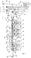
- Fig. 1 shows a fire alarm system 1 with first and second linear heat detectors 2, 3.
- the linear heat detectors 2, 3 each extend through installation space 4, which to monitoring vehicle components 5 to 13 included.
- the first linear heat detectors 2 are arranged in a first strand 18, the second linear heat detectors 3 in a second strand 19.
- the vehicle components to be monitored include, for example, a Saug Vietnamesedrossel or line filter choke 5, motor converter 6, braking resistors 7, auxiliary converters 8, a battery charger 9, Saug Vietnamesekondensatoren 10, DC contactors 11, a power converter 12 and a DC main switch 13th
- First and second linear heat detectors 2, 3 each comprise first and second insulated conductors 14, 15, wherein insulating material is provided between the conductors 14, 15, which loses its insulating property at a predetermined temperature.
- the first conductors 14 are supplied at a first end by a voltage source 16 having a predetermined voltage, which may correspond, for example, to the vehicle electrical system voltage, e.g. 110V.
- the heat detectors 2, 3 of the individual installation spaces 4 are each connected in series in one of the strands 18, 19.
- 4 connection lines 34 are provided between the installation spaces, each electrically connect the ends of a conductor of a linear heat detector 2.3 with an adjacent heat detector 2, 3.
- a strand 18, 19 functions as a continuous linear heat detector, wherein the function of the heat detection is omitted in the areas of the vehicle in which a fire monitoring is required. Consequently, much more robust cable connections between the heat detectors 2, 3 can be used, which make the fire alarm system 1 more robust overall.
- the first conductors 14 are each connected at a second end to an evaluation unit 17, which checks whether a predetermined voltage is present in the connected conductors 14 or whether the measured voltage is within a predetermined interval. If the insulation between a first conductor 14 and a second conductor 15 is lost due to the effect of heat or mechanical action, a short circuit occurs between the conductors 14, 15, as a result of which the predetermined voltage no longer reaches the evaluation unit 17.
- the evaluation unit 17 may comprise a first switching element which is not shown here and electrically conductively connected to the first linear heat detectors 2 and a second switching element which is not shown here and electrically conductively connected to the second heat detector 3.
- the switching elements are preferably designed as a relay, wherein the first and second switching element can be transferred in each case upon triggering of the respective electrically contacted heat detector from a first switching position to a second switching position.
- a first signal 29 is activated, which indicates a defect in the fire alarm system 1. If the second switching element is also transferred to a second switching position, a second signal 30 is generated.
- Each of the switching elements may thus generate a first signal 29 or second signal 30.
- a first signal 29 and a second signal 30 are generated, by which in turn a third signal 20, namely a fire alarm signal is activated.
- the absence or reduced voltage of both strings 18, 19 is detected in the evaluation unit 17 and linked to a fire alarm signal. If initially only a short circuit occurs in the first strand 18 or in the second strand 19, this consequently leads to a first signal 29 in the evaluation unit 17, which indicates a defect in the respective strand 18, 19.
- the signal 29 is passed into a designed for fire detection control system 23, wherein the presence of only one signal according to a defect of a linear heat detector 2, 3 in the first or second strand 18, 19 is designed.
- a short circuit occurs in the remaining strand, this leads to a second signal 30 which, in combination with the first signal 29, indicates a fire.
- the first signal 29 and the second signal 30 are sent in the evaluation unit 17 to a third signal 20, i. linked to a fire alarm signal which is routed to a vehicle bus 21.
- the vehicle bus 21 can be designed for the transmission of fire alarm signals, wherein the signals from the fire alarm system 1 via the vehicle bus 21 and a signal line 22 can reach the oriented to the fire detection part of the control system 23 of the vehicle.
- another vehicle bus 42 is provided for the control of the vehicle.
- the vehicle bus 42 transmits status signals 43 from the Vehicle control system in the control system 23 of the fire alarm system 1, can be started on the example of functional tests of the fire alarm system 1, and receives status information 44 from the control system 23 on the state of the fire alarm system 1.
- fire alarm signals are processed and translated into messages to the driver or used to trigger control signals.
- alarm signals 25 and locating signals 26 can be transmitted to display devices 27 on a driver's desk 28 of the vehicle.
- the control system 23 controls the power supply of the vehicle.
- it can first be determined continuously for each strand 18, 19 of linear heat detectors 2, 3, whether a short circuit is present or heat is detected.
- the control system 23 transmits no-fire signals 32 to an energy management system 33.
- an energy management system 33 For each installation space 4 of the vehicle separately monitored by the linear heat detectors 2, 3 or for each pair of strands 18, 19 of linear heat detectors 2 3, a separate no-fire signal 32 is provided. Only when one of the no-fire signals 32 is no longer present, a shutdown process is triggered in the energy control system 33, by which the power supply of the area affected by the fire is turned off.
- a conventional analog fire alarm is preferably provided in addition to the digital fire alarm.
- the fire alarm signal 20 is passed via the vehicle bus 21 and a fire alarm line 41 in a reporting device 31.
- the reporting device 31 may e.g. be a signal lamp or an acoustic signal generator.
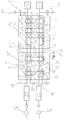
- Fig. 2 shows a further embodiment of a fire detection system 1 according to the invention, wherein the fire alarm system 1 here extends over two car bodies 35, 36.
- the fire alarm system 1 comprises two strands 18, 19, wherein in the first strand 18 first linear heat detectors 2 and second strand 19 second linear heat detectors 3 are arranged ,
- the linear heat detectors 2, 3 preferably each comprise two mutually twisted conductors 14, 15, between which a thermosensitive insulating layer, not shown here, is arranged.
- the conductors 14, 15 are shown here as parallel lines.
- connection lines 34 are provided between connection points of adjacent installation spaces 4.
- connection lines 34 may be conventional connection cables, i. electrical conductors, which are provided with an electrically insulating and protective against environmental influences sheathing.
- connection points 37 in connector elements, i. be arranged in plugs or sockets. Ideally, a plurality of connection points 37, in particular all arranged on one side of an installation space 4 and a car body 35, 36 connection points 37 are combined in each case a plug connection element.
- the first conductors 14 of the linear thermal detectors 2, 3 are each supplied with voltage by a voltage source 16, e.g. with a vehicle electrical system voltage of 110V. Between the voltage sources 16 and the conductors 14, a fuse 39 is arranged in each case.
- the first conductors 14 are connected at their opposite ends of the voltage source 16 to an evaluation unit 17, which may comprise an MIO. Between the first strings 18 and the evaluation units 17 may optionally be arranged low-pass filter 40 to attenuate interference currents from a predetermined frequency.
Abstract
Die Erfindung bezieht sich auf ein Brandmeldesystem (1) für ein Schienenfahrzeug, mit einem ersten linearen Wärmedetektor (2), wobei durch Erwärmung des ersten linearen Wärmedetektors (2) ein erstes Signal (29) aktivierbar ist. Um ein einfach ausgestaltetes und trotzdem sehr zuverlässiges Brandmeldesystem bzw. Brandmeldeverfahren zu schaffen ist ein zweiter linearer Wärmedetektor (3) vorgesehen, der sich im Wesentlichen entlang dem ersten linearen Wärmedetektor (2) erstreckt, wobei durch Erwärmung des zweiten linearen Wärmedetektors (3) ein zweites Signal (30) aktivierbar ist.The invention relates to a fire alarm system (1) for a rail vehicle, having a first linear heat detector (2), wherein a first signal (29) can be activated by heating the first linear heat detector (2). In order to create a simply designed and nevertheless very reliable fire alarm system or fire alarm method, a second linear heat detector (3) is provided, which extends essentially along the first linear heat detector (2), whereby by heating the second linear heat detector (3) a second Signal (30) can be activated.
Description
Die Erfindung betrifft ein Brandmeldesystem für ein Schienenfahrzeug mit einem ersten linearen Wärmedetektor, wobei durch Erwärmung des ersten linearen Wärmedetektors ein erstes Signal aktivierbar ist.The invention relates to a fire alarm system for a rail vehicle with a first linear heat detector, wherein a first signal can be activated by heating the first linear heat detector.
Lineare Wärmedetektoren sind ein etabliertes Mittel zur Brandmeldung, insbesondere zur Erkennung von Bränden in Einbauräumen und Gehäusen ohne aktive Belüftung. Lineare Wärmedetektoren umfassen üblicherweise zwei verdrillte Leitern, die durch ein temperatursensitives Material, z.B. einem Thermoplast oder Fluorpolymer, gegeneinander isoliert sind. Bei Überschreiten einer vordefinierten Alarmtemperatur geht die isolierende Wirkung zwischen den Leitern verloren und es entsteht ein Kurzschluss, der über eine entsprechende elektrische Schaltung einen Alarm auslöst.Linear heat detectors are an established means of fire detection, in particular for the detection of fires in housings and enclosures without active ventilation. Linear thermal detectors usually comprise two twisted conductors which are passed through a temperature-sensitive material, e.g. a thermoplastic or fluoropolymer, are mutually isolated. When a predefined alarm temperature is exceeded, the insulating effect between the conductors is lost and there is a short circuit, which triggers an alarm via a corresponding electrical circuit.
Die
In der
Eine Anwendung derartiger linearer Wärmedetektoren zur Branddetektion in Schienenfahrzeugen ist in der
Ein Problem der Brandmeldesysteme aus dem Stand der Technik ist, dass Brandmeldesignale nur mit großem Aufwand von Fehlern an den linearen Wärmedetektoren oder in der angeschlossenen Spannungsversorgung unterschieden werden können. Entsteht z.B. aufgrund einer Materialermüdung in dem Isoliermaterial eines linearen Wärmedetektors ein Kurzschluss zwischen den Leitern des Wärmedetektors, kann dieser Kurzschluss aufgrund identischer Signale zunächst nicht von einem Kurzschluss aufgrund einer Wärmeentwicklung unterschieden werden. Auch wenn ein elektrischer Kontakt an einem Spannungsanschluss fehlerhaft ist, kann die Stromversorgung eines linearen Wärmedetektors unterbrochen werden, wodurch ein am gegenüberliegenden Ende angeordneter Spannungssensor wie bei einem Kurzschluss ein Brandmeldesignal erkennen würde. In der
Ein Nachteil bekannter Lösungen in Schienenfahrzeugen ist der verhältnismäßig große Aufwand der Implementierung des Brandmeldesystems in das Zugsteuerungssystem. Die Auswertung des Zustands der Wärmedetektoren durch eine Brandmeldeelektronik, die das Zugsteuerungssystem mit den Signalen über den Zustand des Brandmeldesystems versorgt, ist verhältnismäßig kostenaufwändig.A disadvantage of known solutions in rail vehicles is the relatively great expense of implementing the fire alarm system in the train control system. The evaluation of the state of the heat detectors by a fire alarm electronics, which supplies the train control system with the signals on the state of the fire alarm system is relatively expensive.
Ist die Spannungsversorgung eines linearen Wärmedetektors durch einen Kabelbruch in dem Wärmedetektor unterbrochen, kann dies ggf. z.B. durch eine digitale Auswertung von einem Kurzschluss durch Wärmeentwicklung unterschieden werden, weil die beiden Leiter eines Wärmedetektors nicht miteinander in Verbindung treten. Allerdings ist in diesem Fall die Brandmeldung außer Funktion.If the voltage supply of a linear heat detector is interrupted by a cable break in the heat detector, this may be avoided, for example. be differentiated by a digital evaluation of a short circuit due to heat generation, because the two conductors of a heat detector do not connect with each other. However, in this case, the fire alarm is out of order.
Aufgabe der vorliegenden Erfindung ist folglich, ein einfach ausgestaltetes und trotzdem sehr zuverlässiges Brandmeldesystem bzw. Brandmeldeverfahren für ein Schienenfahrzeug zu schaffen.Object of the present invention is therefore to provide a simple ausgestaltetes and still very reliable fire alarm system or fire detection method for a rail vehicle.
Diese Aufgabe wird erfindungsgemäß mit einem Brandmeldesystem nach Anspruch 1 gelöst. Weiterhin wird die Aufgabe mit einem Schienenfahrzeug nach Anspruch und einem Brandmeldeverfahren nach Anspruch 11 gelöst. Das Brandmeldesystem ist für ein Schienenfahrzeug ausgestaltet, insbesondere für technische Gehäuse von Schienenfahrzeugen, z.B. im Unterflurbereich eines Schienenfahrzeuges.This object is achieved with a fire alarm system according to claim 1. Furthermore, the object is achieved with a rail vehicle according to claim and a fire detection method according to
Indem ein zweiter linearer Wärmedetektor vorgesehen ist, der sich im Wesentlichen entlang zum ersten linearen Wärmedetektor erstreckt, wobei durch Erwärmung des zweiten linearen Wärmedetektor ein zweites Signal aktivierbar ist, ist es möglich, zwischen einem Defekt in einem Wärmedetektor und einer Signalauslösung durch Wärmeentwicklung zu unterscheiden. Der zweite lineare Wärmedetektor ist dazu vorzugsweise sehr nah oder unmittelbar am ersten linearen Wärmedetektor verlegt. Idealerweise verläuft der zweite lineare Wärmedetektor abschnittsweise oder über seine gesamte Länge parallel zum ersten linearen Wärmedetektor.By providing a second linear heat detector which extends substantially along the first linear heat detector, wherein a second signal can be activated by heating the second linear heat detector, it is possible to distinguish between a defect in a heat detector and a signal triggering by heat generation. The second linear heat detector is preferably moved very close or directly to the first linear heat detector. Ideally, the second linear heat detector runs in sections or over its entire length parallel to the first linear heat detector.
Entsteht in nur einem Wärmedetektor ein Kurzschluss, wird durch das Brandmeldesystem nur das erste Signal ausgegeben. Die Signale des Brandmeldesystems können vorzugsweise direkt in den Fahrzeugbus geleitet und somit dem Steuerungssystem des Fahrzeuges zugeführt werden. Liegt nur ein erstes Signal der Brandmeldesystems vor, kann das Steuerungssystem aufgrund des Signals des Brandmeldesystems einen Hinweis auf einen Defekt im Brandmeldesystem ausgeben. Ein derartiger Effekt im Brandmeldesystem führt dabei gegenüber herkömmlichen Brandmeldesystemen nicht zu einem Ausfall der Brandmeldefunktion. Erst wenn auch in dem zweiten, parallel zum ersten Wärmedetektor angeordneten Wärmedetektor ein Kurzschluss vorliegt, wird ein zweites Signal aktiviert, das ebenfalls dem Steuerungssystem zugeführt werden und in Kombination mit dem ersten Signal eine Brandmeldung auslösen kann.If a short circuit occurs in just one heat detector, only the first signal is output by the fire alarm system. The signals of the fire alarm system can preferably be passed directly into the vehicle bus and thus supplied to the control system of the vehicle. If only a first signal of the fire alarm system is present, the control system can give an indication of a defect in the fire alarm system due to the signal of the fire alarm system. Such an effect in the fire alarm system does not lead to failure of the fire alarm function compared to conventional fire alarm systems. Only when there is a short circuit in the second heat detector arranged parallel to the first heat detector, a second signal is activated, which is likewise fed to the control system and can trigger a fire alarm in combination with the first signal.
Weitere Ausführungsformen, Modifikationen und Verbesserungen ergeben sich anhand der folgenden Beschreibung und der beigefügten Ansprüche.Other embodiments, modifications and improvements will become apparent from the following description and the appended claims.
In einer ersten bevorzugten Weiterbildung des erfindungsgemäßen Brandmeldesystems ist durch gleichzeitige Erwärmung des ersten und des zweiten Wärmedetektors ein drittes Signal aktivierbar. Das dritte Signal kann über eine elektrische Verbindung in eine Brandmeldeanlage, z.B. eine Warnlampe oder einen Lautsprecher geleitet werden. Vorzugsweise wird das dritte Signal in einen Fahrzeugbus geleitet, um eine Verarbeitung des Signals im Zugsteuerungssystem zu ermöglichen und den Fahrzeugführer oder die Fahrzeugleitstelle ggf. mit Informationen über die auf einen Brand hinweisende Wärmeentwicklung zu beliefern.In a first preferred development of the fire alarm system according to the invention, a third signal can be activated by simultaneous heating of the first and the second heat detector. The third signal can be passed via an electrical connection in a fire alarm system, such as a warning lamp or a speaker. Preferably, the third signal is passed into a vehicle bus to allow processing of the signal in the train control system and the driver or the If necessary, to provide the vehicle control center with information on the heat development indicative of a fire.
Gemäß einer weiteren vorteilhaften Ausgestaltung der Erfindung kann ein mit dem ersten Wärmedetektor elektrisch kontaktiertes erstes Schaltelement und ein mit dem zweiten Wärmedetektor elektrisch kontaktiertes zweites Schaltelement vorgesehen sein, wobei erstes und zweites Schaltelement jeweils bei Auslösung des jeweiligen elektrisch kontaktierten Wärmedetektors von einer ersten Schaltposition in eine zweite Schaltposition überführbar sind. Um zwischen einer Wärmeentwicklung bzw. einem Brand im Fahrzeug und einem Defekt im Brandmeldesystem unterscheiden zu können, ist bevorzugt in einem ersten Betriebszustand des Brandmeldesystems, in welchem das erste Schaltelement in der ersten Schaltposition und das zweite Schaltelement in der zweiten Schaltposition positioniert ist, das erste Signal aktiviert, und in einem zweiten Betriebszustand, in welchem beide Schaltelemente in der zweiten Schaltposition positioniert sind, das dritte Signal aktiviert.In accordance with a further advantageous embodiment of the invention, a first switching element electrically contacted with the first heat detector and a second switching element electrically contacted with the second heat detector may be provided, wherein the first and second switching elements each trigger a respective first electrically connected heat detector from a first switching position to a second switching element Switching position can be transferred. In order to be able to distinguish between a heat development or a fire in the vehicle and a defect in the fire alarm system, the first is preferably in a first operating state of the fire alarm system in which the first switching element is positioned in the first switching position and the second switching element in the second switching position Signal is activated, and in a second operating state, in which both switching elements are positioned in the second switching position, the third signal activated.
In einer weiteren bevorzugten Ausführung der Erfindung ist ein drittes Schaltelement vorgesehen, das mit erstem und zweitem Schaltelement signalübertragend verbunden ist und bei Auslösung des ersten und des zweiten Schaltelementes auslöst. Mit dem dritten Schaltelement kann ein diskretes Signal erzeugt werden, das eindeutig auf eine Erwärmung beider Wärmedetektoren hinweist. Das erste und das zweite Schaltelement können beispielsweise in einer Signalübertragungsleitung parallel geschaltet sein, wobei eine Signalübertragung stattfindet, so lange eines der Schaltelemente geschlossen ist. Erst wenn beide Schaltelemente auslösen, d.h. den jeweils zugeordneten Zweig der Signalübertragungsleitung unterbrechen, findet keine Signalübertragung mehr in der Signalübertragungsleitung statt, wobei durch das Ausbleiben des Signals das dritte Schaltelement vorzugsweise ausgelöst wird.In a further preferred embodiment of the invention, a third switching element is provided, which is signal-transmitting connected to the first and second switching element and triggers upon triggering of the first and the second switching element. With the third switching element, a discrete signal can be generated, which clearly indicates heating of both heat detectors. The first and the second switching element may, for example, be connected in parallel in a signal transmission line, signal transmission taking place as long as one of the switching elements is closed. Only when both switching elements trigger, i. interrupt the respectively associated branch of the signal transmission line, no signal transmission takes place in the signal transmission line, which is preferably triggered by the absence of the signal, the third switching element.
Erste, zweite und/oder dritte Schaltelemente können als elektromechanische oder elektronische Schalter ausgestaltet sein. Vorzugsweise werden Relais als Schaltelemente verwendet. Die Schaltelemente können unmittelbar über die Wärmedetektoren mit einer Spannungsquelle verbunden sein, so dass eine Brandmeldung erfolgen kann, ohne dass eine elektronische Auswertung Prüfspannung erforderlich ist.First, second and / or third switching elements can be configured as electromechanical or electronic switches. Preferably, relays are used as switching elements. The switching elements can be connected directly via the heat detectors with a voltage source, so that a fire can be done without an electronic evaluation test voltage is required.
Gemäß einer weiteren bevorzugten Weiterbildung der Erfindung können durch das dritte Schaltelement analoge Signalgeber, wie Signalleuchten oder Warntöne ausgelöst werden. Das dritte Schaltelement kann einen Stromkreis schließen, der einen Signalgeber mit Strom versorgt. Somit kann die Brandmeldung rein analog erfolgen. Die Brandmeldung kann zudem unabhängig von elektronischen bzw. digitalen Steuereinrichtungen des Schienenfahrzeuges betrieben werden.According to a further preferred embodiment of the invention can be triggered by the third switching element analog signal generator, such as signal lights or warning tones. The third switching element may close a circuit which is a signal generator with power provided. Thus, the fire can be done purely analog. The fire alarm can also be operated independently of electronic or digital control devices of the rail vehicle.
Vorzugsweise grenzen erster und zweiter linearer Wärmedetektor über einen Großteil ihrer Länge aneinander an. Die Wärmedetektoren können über wenigstens 50 % ihrer Länge aneinander angrenzen, vorzugsweise über wenigstens 80 % ihrer Länge, äußerst bevorzugt über wenigstens 90 % ihrer Länge. Somit wird sichergestellt, dass die Wärmedetektoren bei Auftreten eines Brandes gleichzeitig oder wenigstens kurz hintereinander das jeweils zugeordnete Signal auslösen, ohne dass es zu Fehlinterpretationen der ausgelösten Signale kommt.Preferably, the first and second linear thermal detectors adjoin one another for a majority of their length. The heat detectors may be adjacent to each other for at least 50% of their length, preferably over at least 80% of their length, most preferably over at least 90% of their length. This ensures that the heat detectors simultaneously or at least shortly after one another trigger the respectively assigned signal in the event of a fire, without resulting in misinterpretations of the triggered signals.
In einer weiteren Variante der Erfindung kann das Brandmeldesystem einen ersten und einen zweiten Strang aufweisen, wobei die Stränge jeweils lineare Wärmedetektoren umfassen und jeweils in einem Strang wenigstens zwei Wärmedetektoren in Reihe geschaltet sind. Zwischen den in Reihe geschalteten Wärmedetektoren können elektrisch leitende Verbindungsleitungen vorgesehen sein.In a further variant of the invention, the fire alarm system may have a first and a second strand, the strands each comprising linear heat detectors and in each case at least two heat detectors are connected in series in a strand. Between the series-connected heat detectors electrically conductive connection lines can be provided.
Die maximale Länge eines linearen Wärmedetektors ist durch den elektrischen Widerstand seiner begrenzt. Um möglichst viele Komponenten mit nur zwei linearen Wärmedetektoren überwachen zu können, weisen diese idealerweise eine Länge von wenigstens 0,3 m oder mehr als 1 m auf, vorzugsweise von mehr als 5 m oder mehr als 10 m.The maximum length of a linear heat detector is limited by the electrical resistance of it. In order to be able to monitor as many components as possible with only two linear heat detectors, they ideally have a length of at least 0.3 m or more than 1 m, preferably more than 5 m or more than 10 m.
Die Wärmedetektoren umfassen bevorzugt jeweils zwei zueinander isolierte Leiter, wobei das isolierende Material zwischen den Leitern bei einer vorbestimmten Temperatur seine isolierende Eigenschaft verliert bzw. aufschmilzt. Sobald die Isolierung zwischen den Leitern verloren gegangen ist, entsteht ein Kurzschluss, der ein Signal auslöst. Das isolierende Material zwischen den Leitern kann z.B. ein Fluorpolymer enthalten. Um mechanische Beschädigungen der Isolierung und der Leiter zu vermeiden, die zu Fehlsignalen führen könnten, können die linearen Wärmedetektoren mit einer äußeren Schutzschicht aus PVC versehen und/oder in einem Schlauch aus Polyamid eingebettet sein.The heat detectors preferably each comprise two mutually insulated conductors, wherein the insulating material between the conductors at a predetermined temperature loses its insulating property or melts. As soon as the insulation between the conductors has been lost, a short circuit is created which triggers a signal. The insulating material between the conductors may e.g. contain a fluoropolymer. In order to avoid mechanical damage to the insulation and the conductors, which could lead to false signals, the linear thermal detectors may be provided with an external protective layer of PVC and / or embedded in a polyamide tube.
Ein erfindungsgemäßes Schienenfahrzeug mit einem Brandmeldesystem gemäß einer der oben beschriebenen Ausführungen kann in einer bevorzugten Variante mit einem Fahrzeugbus versehen sein, wobei das erste und das zweite Schaltelement signalübertragend mit dem Fahrzeugbus verbunden sein können. An den Fahrzeugbus kann des Weiteren eine Steuereinrichtung angeschlossen sein, welche die Signale des Brandmeldesystems aufnimmt und auswertet. Somit können Signale aus dem Brandmeldesystem nicht nur für Mitteilungen an den Zugführer verwendet werden, sondern auch mit Signalen aus anderen Komponenten des Fahrzeugs kombiniert werden. Z.B. kann die Meldung einer Funktionsstörung einer durch das Brandmeldesystem überwachten Komponente bei gleichzeitigem Auftreten einer Brandmeldung zu einem Hinweis auf den Ort der Wärmeentwicklung kombiniert werden.An inventive rail vehicle with a fire alarm system according to one of the embodiments described above may be provided in a preferred variant with a vehicle bus, wherein the first and the second switching element can be signal transmitting connected to the vehicle bus. To the vehicle bus can Furthermore, a control device can be connected, which receives and evaluates the signals of the fire alarm system. Thus, signals from the fire alarm system can not only be used for messages to the driver, but also be combined with signals from other components of the vehicle. For example, the message of a malfunction of a monitored by the fire alarm system component can be combined with the simultaneous occurrence of a fire to an indication of the location of heat generation.
In den Fahrzeugbus übertragene Brandmeldesignale können genutzt werden, um über eine Steuereinrichtung des Fahrzeuges automatisch Vorgänge zur Eindämmung eines möglichen Brandes und zum Schutz von Passagieren zu starten. Neben einer Erzeugung eines Brandmeldesignals, z.B. indem eine Anzeigelampe eingeschaltet wird, kann eine Nachricht auf einer Anzeige des Führerstandes erzeugt werden, mit welcher der Fahrzeugführer über den betroffenen Wagen und/oder die betroffene Komponente informiert wird. Des Weiteren kann eine ggf. vorhandene aktive Belüftung des betroffenen Bereiches ausgeschaltet werden, und/oder die Hochspannungsversorgung der betroffenen Ausrüstung kann unterbrochen werden.Fire alarm signals transmitted to the vehicle bus can be used to automatically initiate operations to curb a possible fire and to protect passengers via a control device of the vehicle. In addition to generating a fire alarm signal, e.g. by turning on an indicator light, a message can be generated on a display of the driver's cab which informs the driver about the car involved and / or the component concerned. Furthermore, possibly existing active ventilation of the affected area can be switched off, and / or the high-voltage supply of the equipment concerned can be interrupted.
In einer bevorzugten Ausführung der Erfindung erstreckt sich das Brandmeldesystem über wenigstens zwei Einbauräume oder über zwei Unterflurkomponenten. Vorzugsweise erstreckt sich das Brandmeldesystem über mehr als fünf oder mehr als zehn Einbauräume oder Unterflurkomponenten. Im Zuge dessen können sich erste und zweite linearer Wärmedetektoren über wenigstens zwei Einbauräume erstrecken. Auf diese Weise werden die Materialkosten und der Montageaufwand für die Montage des Brandmeldesystems verringert. Die Unterflurkomponenten können eine Saugkreisdrossel, eine Netzfilterdrossel, einen Motorstromrichter, wenigstens einen Bremswiderstand, einen Hilfsbetriebeumrichter, ein Batterieladegerät, wenigstens einen Saugkreiskondensator, wenigstens ein Schütz, wenigstens einen Netzstromrichter und/oder einen Hauptschalter umfassen. Die Unterflurkomponenten können jeweils in separaten Gehäusen untergebracht oder durch Trennwände voneinander getrennt sein, um einen entstehenden Brandherd von benachbarten Komponenten zu trennen.In a preferred embodiment of the invention, the fire alarm system extends over at least two installation spaces or over two underfloor components. The fire alarm system preferably extends over more than five or more than ten installation spaces or underfloor components. In the course of this, first and second linear heat detectors can extend over at least two installation spaces. In this way, the material costs and installation costs for the installation of the fire alarm system are reduced. The underfloor components may include a Saugkreisdrossel, a line filter choke, a motor power converter, at least one braking resistor, auxiliaries converter, a battery charger, at least one Saugkreiskondensator, at least one contactor, at least one mains converter and / or a main switch. The underfloor components may each be housed in separate housings or separated from one another by partitions to separate a developing fire from adjacent components.
Eine vorteilhafte Weiterbildung der Erfindung sieht vor, dass in zu überwachenden Einbauräumen lineare Wärmedetektoren verlaufen, wobei lineare Wärmedetektoren aus benachbarten Einbauräumen miteinander elektrisch leitend verbunden sind. Die elektrische Verbindung benachbarter linearer Wärmedetektoren kann über Verbindungsleitungen erfolgen, die herkömmliche elektrische Leiter umfassen können. Benachbarte lineare Wärmedetektoren können zur Vereinfachung der Montage über Steckverbindungen an einen Verbindungsleitungen angeschlossen sein. Des Weiteren können lineare Wärmedetektoren über Steckverbindungen an die Spannungsversorgung angeschlossen sein. Um auf eine Spannungswandlung für den Anschluss der Wärmedetektoren verzichten zu können, sind die Wärmedetektoren idealerweise an die Spannung des Bordnetzes angepasst. Die Bordnetzspannung kann z.B. 110V betragen.An advantageous development of the invention provides that linear heat detectors run in the installation spaces to be monitored, wherein linear heat detectors from adjacent installation spaces are connected to one another in an electrically conductive manner. The electrical connection of adjacent linear heat detectors can via connecting lines take place, which may include conventional electrical conductors. Adjacent linear heat detectors may be connected to a connection line via connectors for ease of assembly. Furthermore, linear heat detectors can be connected via plug connections to the power supply. To be able to dispense with a voltage conversion for the connection of the heat detectors, the heat detectors are ideally adapted to the voltage of the electrical system. The vehicle electrical system voltage can be eg 110V.
Für die Übertragung von Signalen in ein digitales Zugsteuerungssystem können digitale Auswerteeinheiten, insbesondere modulare Input-/Output-Systeme (MIO) vorgesehen sein, die z.B. an einem Eingang an die über einen linearen Wärmedetektor übertragenen Spannung angeschlossen sind. Bevorzugt werden modulare Input-/Output-Systeme verwendet, die wenigstens dem Sicherheits-Integritätslevel 2 (SIL2) nach IEC 61508 bzw. IEC6 1511 entsprechen. Entsprechend der Eingangsspannung kann aus dem MIO ein Signal an das Zugsteuerungssystem übertragen werden, wobei z.B. eine vorhandene, vorbestimmte Spannung auf einen fehlerfreien Betrieb hinweist, während ein Spannungsabfall auf eine Wärmedetektion oder einen Kabelbruch hindeutet. Erster und zweiter linearer Wärmedetektor können jeweils an separate MIO-Einheiten angeschlossen sein, um zu vermeiden, dass der Ausfall einer MIO-Einheit einen Ausfall beider Wärmedetektoren zur Folge hat.For the transmission of signals in a digital train control system, digital evaluation units, in particular modular input / output systems (MIO) may be provided, which may be e.g. are connected at an input to the voltage transmitted via a linear heat detector voltage. Preference is given to the use of modular input / output systems which at least correspond to safety integrity level 2 (SIL2) according to IEC 61508 or IEC61511. Depending on the input voltage, a signal may be transmitted from the MIO to the train control system, e.g. an existing, predetermined voltage indicates a fault-free operation, while a voltage drop indicates a heat detection or a cable break. First and second linear thermal detectors can each be connected to separate MIO units to prevent the failure of one MIO unit resulting in failure of both heat detectors.
Ein linearer Wärmedetektor kann derart angeschlossen sein, dass ein erster Leiter des Wärmedetektors mit einer Überwachungsspannung versorgt wird, während ein zweiter Leiter mit dem Nullpotential des Fahrzeugs verbunden bzw. geerdet wird. Ein mit dem ersten Leiter des Wärmedetektors verbundenes MIO kann nun die Überwachungsspannung bzw. die Spannungsdifferenz zum zweiten Leiter des Wärmedetektors detektieren, so lange erster und zweiter Leiter des Wärmedetektors zueinander isoliert sind, d.h. es kann z.B. ein Signal "high" ausgegeben werden, so lange die Spannung am entsprechenden Eingang des MIO größer als ein vorbestimmter Minimalwert ist. Tritt nun ein Kurzschluss zwischen erstem und zweitem Leiter des Wärmedetektors auf, fällt die detektierte Spannung ab und das MIO erzeugt ein Signal "low".A linear thermal detector may be connected such that a first conductor of the thermal detector is supplied with a monitoring voltage, while a second conductor is connected to the zero potential of the vehicle or grounded. A MIO connected to the first conductor of the thermal detector can now detect the monitor voltage or voltage difference to the second conductor of the thermal detector as long as the first and second conductors of the thermal detector are isolated from each other, i. it can e.g. a signal "high" are output as long as the voltage at the corresponding input of the MIO is greater than a predetermined minimum value. If a short circuit occurs between the first and the second conductor of the heat detector, the detected voltage drops and the MIO generates a signal "low".
Gemäß einer alternativen, ebenso vorteilhaften Ausführungsform der Erfindung ist wenigstens einer der Einbauräume des Schienenfahrzeuges mit einem eigenständigen erfindungsgemäßen Brandmeldesystem ausgestattet. Durch das zusätzliche Brandmeldesystem wird eine Redundanz erzeugt und die Ausfallsicherheit erhöht. Zugleich ist bei einer Auslösung eines Signals dieses Brandmeldesystems eindeutig erkennbar, in welchem Einbauraum ggf. ein Defekt eines Wärmedetektors oder eine Wärmeentwicklung zu lokalisieren ist. Ein derartiges zusätzliches Brandmeldesystem kann insbesondere in Einbauräumen von Komponenten mit hohem Brandrisiko angeordnet werden.According to an alternative, equally advantageous embodiment of the invention, at least one of the installation spaces of the rail vehicle is equipped with an independent fire detection system according to the invention. The additional fire alarm system creates redundancy and increases the reliability. at the same time If a signal of this fire alarm system is triggered, it can be clearly recognized in which installation space, if necessary, a defect of a heat detector or heat generation can be located. Such an additional fire alarm system can be arranged in particular in installation spaces of components with high fire risk.
In einem erfindungsgemäßen Brandmeldeverfahren für ein erfindungsgemäßes Schienenfahrzeug wird die oben genannte Aufgabe gelöst,, indem bei Erhitzung eines ersten Wärmedetektors ein erstes Signal durch den ersten Wärmedetektor erzeugt wird, anschließend bei Erhitzung eines zweiten Wärmedetektors durch den zweiten Wärmedetektor ein zweites Signal erzeugt wird und schließlich, bei gleichzeitigem Vorhandensein des ersten und den zweiten Signals, ein drittes Signal erzeugt wird, das eine Brandmeldung auslöst.In a fire detection method according to the invention for a rail vehicle according to the invention, the above-mentioned object is achieved by generating a first signal by the first heat detector when a first heat detector is heated, then by heating a second heat detector by the second heat detector generating a second signal and finally in the presence of the first and the second signal, a third signal is generated, which triggers a fire.
Gemäß einer Weiterbildung des Brandmeldeverfahrens ist vorgesehen, dass das Steuerungssystem des Schienenfahrzeugs Signale des Brandmeldesystems aufnimmt und auswertet, wobei Fehlermeldungen aus Diagnoseprogrammen des Schienenfahrzeuges mit Signalen des Brandmeldesystems verknüpft werden. Auf diese Weise können genauere Hinweise über die Ursache und den Ort der Wärmeentwicklung gesammelt werden.According to one embodiment of the fire alarm system is provided that the control system of the rail vehicle receives and evaluates signals of the fire alarm system, error messages are linked from diagnostic programs of the rail vehicle with signals from the fire alarm system. In this way, more accurate information about the cause and location of the heat development can be collected.
In einer Weiterführung dieses Gedankens können Fehlermeldungen zu einzelnen Komponenten des Schienenfahrzeuges mit Signalen des Brandmeldesystems verknüpft werden, um einen Hinweis über den Ort der Wärmeentwicklung zu generieren.In a continuation of this idea, error messages relating to individual components of the rail vehicle can be linked to signals from the fire alarm system in order to generate an indication of the location of the heat development.
Die beiliegenden Zeichnungen veranschaulichen erfindungsgemäße Ausführungsformen und dienen zusammen mit der Beschreibung der Erläuterung der Prinzipien der Erfindung. Im Folgenden werden unter Bezugnahme auf die
-
Fig. 1 ist ein Schaltbild einer ersten Ausführungsform eines erfindungsgemäßen Brandmeldesystems mit einer Anordnung von Wärmedetektoren in einem Wagen eines Schienenfahrzeugs. -
Fig. 2 ist ein Schaltbild einer zweiten Ausführungsform eines erfindungsgemäßen Brandmeldesystems, das zwei Wagen eines Schienenfahrzeugs umfasst.
-
Fig. 1 is a circuit diagram of a first embodiment of a fire detection system according to the invention with an array of heat detectors in a car of a rail vehicle. -
Fig. 2 is a circuit diagram of a second embodiment of a fire detection system according to the invention comprising two cars of a rail vehicle.
Erste und zweite lineare Wärmedetektoren 2, 3 umfassen jeweils erste und zweite zueinander isolierte Leiter 14, 15 wobei zwischen den Leitern 14, 15 isolierendes Material vorgesehen ist, das bei einer vorbestimmten Temperatur seine isolierende Eigenschaft verliert bzw. aufschmilzt. Um den Verlust der Isolierung zwischen den Leitern 14, 15 detektieren zu können, sind die ersten Leiter 14 an einem ersten Ende durch eine Spannungsquelle 16 mit einer vorbestimmten Spannung versorgt, die beispielsweise der Bordnetzspannung entsprechen kann und z.B. 110V betragen kann.First and second
Um die Versorgung der Wärmedetektoren 2, 3 mit der vorgesehenen Spannung einfach zu gestalten, sind die Wärmedetektoren 2, 3 der einzelnen Einbauräume 4 jeweils in einem der Stränge 18, 19 in Reihe geschaltet. Dazu sind zwischen den Einbauräumen 4 Verbindungsleitungen 34 vorgesehen, die jeweils die Enden eines Leiters aus einem linearen Wärmedetektor 2,3 mit einem benachbarten Wärmedetektor 2, 3 elektrisch leitend verbinden. Auf diese Weise funktioniert ein Strang 18, 19 wie ein durchgehender linearer Wärmedetektor, wobei in den Bereichen des Fahrzeugs, in welchen eine Brandüberwachung erforderlich ist, auf die Funktion der Wärmedetektion verzichtet wird. Es können folglich sehr viel robustere Kabelverbindungen zwischen den Wärmedetektoren 2, 3 verwendet werden, die das Brandmeldesystem 1 insgesamt robuster machen.In order to make the supply of the
Die ersten Leiter 14 sind jeweils an einem zweiten Ende mit einer Auswerteeinheit 17 verbunden, die prüft, ob in den angeschlossenen Leitern 14 eine vorbestimmte Spannung vorhanden ist bzw. ob die gemessene Spannung in einem vorbestimmten Intervall liegt. Geht die Isolierung zwischen einem ersten Leiter 14 und einem zweiten Leiter 15 aufgrund von Wärmeinwirkung oder mechanischer Einwirkung verloren, entsteht ein Kurzschluss zwischen den Leitern 14, 15, aufgrund dessen die vorbestimmte Spannung nicht mehr an die Auswerteeinheit 17 gelangt.The
Die Auswerteeinheit 17 kann ein, hier nicht dargestelltes, mit den ersten linearen Wärmedetektoren 2 elektrisch leitend verbundenes erstes Schaltelement und ein, hier nicht dargestelltes, mit dem zweiten Wärmedetektor 3 elektrisch leitend verbundenes zweites Schaltelement umfassen. Die Schaltelemente sind bevorzugt als Relais ausgeführt, wobei erstes und zweites Schaltelement jeweils bei Auslösung des jeweiligen elektrisch kontaktierten Wärmedetektors von einer ersten Schaltposition in eine zweite Schaltposition überführbar sind. In einem ersten Betriebszustand des Brandmeldesystems 1, in welchem das erste Schaltelement in der ersten Schaltposition und das zweite Schaltelement in der zweiten Schaltposition positioniert ist, ist ein erstes Signal 29 aktiviert, das auf einen Defekt in dem Brandmeldesystem 1 hinweist. Wird auch das zweite Schaltelement in eine zweite Schaltposition überführt, wird ein zweites Signal 30 erzeugt. Jedes der Schaltelemente kann folglich ein erstes Signal 29 oder zweites Signal 30 erzeugen. In einem zweiten Betriebszustand, in welchem beide Schaltelemente in der zweiten Schaltposition positioniert sind, wird ein erstes Signal 29 und ein zweites Signal 30 erzeugt, durch welche wiederum ein drittes Signal 20, nämlich ein Brandmeldesignal, aktiviert wird.The
Liegt in beiden Strängen 18 und 19 jeweils wenigstens ein Kurzschluss zwischen einem ersten Leiter 14 und einem zweiten Leiter 15 vor, wird das Fehlen bzw. die reduzierte Spannung beider Stränge 18, 19 in der Auswerteeinheit 17 erfasst und zu einem Brandmelde-Signal verknüpft. Tritt zunächst nur ein Kurzschluss im ersten Strang 18 oder im zweiten Strang 19 auf, führt dies folglich zu einem ersten Signal 29 in der Auswerteeinheit 17, das einen Defekt in dem jeweiligen Strang 18, 19 anzeigt. Das Signal 29 wird in ein für die Branderkennung ausgestaltetes Steuerungssystem 23 geleitet, wobei das Vorliegen nur eines Signals entsprechend als Defekt eines linearen Wärmedetektor 2, 3 in dem ersten oder zweiten Strang 18, 19 ausgelegt wird.If there is at least one short circuit between a
Tritt ein Kurzschluss in dem verbliebenen Strang auf, führt dieser zu einem zweiten Signal 30, das in Kombination mit dem ersten Signal 29 auf einen Brand hinweist. Erstes Signal 29 und zweites Signal 30 werden in der Auswerteeinheit 17 zu einem dritten Signal 20, d.h. zu einem Brandmeldesignal verknüpft, das in einen Fahrzeugbus 21 geleitet wird.If a short circuit occurs in the remaining strand, this leads to a second signal 30 which, in combination with the first signal 29, indicates a fire. The first signal 29 and the second signal 30 are sent in the
Der Fahrzeugbus 21 kann für die Übertragung von Brandmeldesignalen ausgestaltet sein, wobei die Signale aus dem Brandmeldesystem 1 über den Fahrzeugbus 21 und eine Signalleitung 22 in den auf die Branderkennung ausgerichteten Teil des Steuerungssystems 23 des Fahrzeugs gelangen können. Für die Steuerung des Fahrzeugs ist ein weiterer Fahrzeugbus 42 vorgesehen. Der Fahrzeugbus 42 überträgt Statussignale 43 aus dem Fahrzeugsteuerungssystem in das Steuerungssystem 23 des Brandmeldesystems 1, über die z.B. Funktionsprüfungen des Brandmeldesystems 1 gestartet werden können, und empfängt Statusinformationen 44 aus dem Steuerungssystem 23 über den Zustand des Brandmeldesystems 1. In dem Steuerungssystem 23 werden Brandmeldesignale verarbeitet und in Mitteilungen an den Fahrzeugführer übersetzt oder zur Auslösung von Steuerungssignalen verwendet. Z.B. können aus dem Steuerungssystem 23 Brandmeldesignale 24, Alarmsignale 25 und Ortungssignale 26 an Anzeigegeräte 27 auf einem Führerpult 28 des Fahrzeugs übertragen werden.The
In dem Ausführungsbeispiel der
Um auch bei einem Ausfall des Steuerungssystems 23 eine Brandmeldung zu erhalten, ist bevorzugt neben der digitalen Brandmeldung eine konventionelle analoge Brandmeldung vorgesehen. Dazu wird das Brandmeldesignal 20 über den Fahrzeugbus 21 und eine Brandmeldeleitung 41 in eine Meldeeinrichtung 31 geleitet. Die Meldeeinrichtung 31 kann z.B. eine Signallampe oder ein akustischer Signalgeber sein.In order to obtain a fire alarm even if the
Die Leiter 14, 15 sind an ihren Enden jeweils an Anschlusspunkte 37 angeschlossen. Um die Leiter 14, 15 benachbarter linearer Wärmedetektoren miteinander zu verbinden, sind zwischen Anschlusspunkten benachbarter Einbauräume 4 jeweils Verbindungsleitungen 34 vorgesehen. Gleichermaßen sind zwischen den benachbarten Wagenkästen 35, 36 Verbindungsleitungen 34 angeordnet, die erste Leiter 14 und zweite Leiter 15 mit benachbarten ersten Leitern 14 und zweiten Leitern 15 verbinden. Die Verbindungsleitungen 34 können herkömmliche Verbindungskabel sein, d.h. elektrische Leiter, die mit einer elektrisch isolierenden und vor Umgebungseinflüssen schützenden Ummantelung versehen sind. Um den Anschluss bzw. die Verbindung der linearen Wärmedetektoren zu vereinfachen, können die Anschlusspunkte 37 in Steckverbindungselementen, d.h. in Steckern oder Steckdosen angeordnet sein. Idealerweise sind mehrere Anschlusspunkte 37, insbesondere sämtliche an einer Seite eines Einbauraums 4 bzw. eines Wagenkastens 35, 36 angeordneten Anschlusspunkte 37 in jeweils einem Steckverbindungselement zusammengefasst.The
Die ersten Leiter 14 der linearen Wärmedetektoren 2, 3 werden jeweils durch eine Spannungsquelle 16 mit einer Spannung versorgt, z.B. mit einer Bordnetzspannung von 110V. Zwischen der Spannungsquellen 16 und den Leitern 14 ist jeweils eine Sicherung 39 angeordnet. Die ersten Leiter 14 sind an ihren der Spannungsquelle 16 gegenüberliegenden Enden an eine Auswerteeinheit 17 angeschlossen, die ein MIO umfassen kann. Zwischen den ersten Strängen 18 und den Auswerteeinheiten 17 können optional Tiefpassfilter 40 angeordnet sein, um Störströme ab einer vorbestimmten Frequenz zu dämpfen.The
Die beschriebenen und dargestellten spezifischen Ausführungsformen sind für die Ausführung der Erfindung nicht bindend, sondern können im Rahmen der vorliegenden Erfindung geeignet modifiziert werden, ohne vom Schutzbereich der vorliegenden Erfindung abzuweichen.The specific embodiments described and illustrated are not binding upon the practice of the invention, but may be suitably modified within the scope of the present invention without departing from the scope of the present invention.
- 11
- BrandmeldesystemFire Alarm System
- 22
- erster linearer Wärmedetektorfirst linear heat detector
- 33
- zweiter linearer Wärmedetektorsecond linear heat detector
- 44
- Einbaurauminstallation space
- 55
- NetzfilterdrosselLine reactor
- 66
- MotorstromrichterMotor converter
- 77
- Bremswiderstandbraking resistor
- 88th
- HilfsbetriebeumrichterAuxiliary Converter
- 99
- Batterieladegerätbattery charger
- 1010
- SaugkreiskondensatorSaugkreiskondensator
- 1111
- Gleichspannungs-SchützeDC contactors
- 1212
- NetzstromrichterPower converter
- 1313
- Hauptschaltermain switch
- 1414
- Erster LeiterFirst leader
- 1515
- Zweiter LeiterSecond leader
- 1616
- Spannungsquellevoltage source
- 1717
- Auswerteeinheitevaluation
- 1818
- Erster StrangFirst strand
- 1919
- Zweiter StrangSecond strand
- 2020
- Drittes Signal (Brandmeldesignal)Third signal (fire alarm signal)
- 2121
- Fahrzeugbusvehicle bus
- 2222
- Signalleitungsignal line
- 2323
- Steuerungssystemcontrol system
- 2424
- BrandmeldesignalFire alarm signal
- 2525
- Alarmsignalalarm
- 2626
- Ortungssignallocating signal
- 2727
- Anzeigegerätdisplay
- 2828
- Führerpultdriver's console
- 2929
- Erstes SignalFirst signal
- 3030
- Zweites SignalSecond signal
- 3131
- Meldeeinrichtungsignaling device
- 3232
- Kein-Brand-SignalNo-fire signal
- 3333
- EnergiesteuerungssystemEnergy Control System
- 3434
- Verbindungsleitungconnecting line
- 3535
- Wagenkastencar body
- 3636
- Wagenkastencar body
- 3737
- Anschlusspunkteconnection points
- 3939
- Sicherungfuse
- 4040
- TiefpassfilterLow Pass Filter
- 4141
- BrandmeldeleitungFire alarm line
- 4242
- Fahrzeugbusvehicle bus
- 4343
- Statussignalstatus signal
- 4444
- Statusinformationstatus information
Claims (13)
Applications Claiming Priority (1)
| Application Number | Priority Date | Filing Date | Title |
|---|---|---|---|
| DE102016125490.8A DE102016125490A1 (en) | 2016-12-22 | 2016-12-22 | Fire alarm system for a rail vehicle |
Publications (1)
| Publication Number | Publication Date |
|---|---|
| EP3340200A1 true EP3340200A1 (en) | 2018-06-27 |
Family
ID=60915292
Family Applications (1)
| Application Number | Title | Priority Date | Filing Date |
|---|---|---|---|
| EP17209681.0A Withdrawn EP3340200A1 (en) | 2016-12-22 | 2017-12-21 | Fire alarm system for a rail vehicle |
Country Status (2)
| Country | Link |
|---|---|
| EP (1) | EP3340200A1 (en) |
| DE (1) | DE102016125490A1 (en) |
Cited By (1)
| Publication number | Priority date | Publication date | Assignee | Title |
|---|---|---|---|---|
| CN112489347A (en) * | 2020-10-30 | 2021-03-12 | 哈尔滨飞机工业集团有限责任公司 | Continuous fire alarm detection system and method |
Citations (4)
| Publication number | Priority date | Publication date | Assignee | Title |
|---|---|---|---|---|
| US5172099A (en) * | 1990-05-15 | 1992-12-15 | Walter Kidde Aerospace Inc. | Self monitoring fire detection system |
| EP0530012A1 (en) * | 1991-08-30 | 1993-03-03 | BICC Public Limited Company | Heat-detector cable installations and cables for use in them |
| WO2005027147A1 (en) * | 2003-07-09 | 2005-03-24 | Geir Jensen | String device |
| WO2008031627A1 (en) * | 2006-09-15 | 2008-03-20 | Bombardier Transportation Gmbh | Rail vehicle with a fire detection device |
Family Cites Families (10)
| Publication number | Priority date | Publication date | Assignee | Title |
|---|---|---|---|---|
| US2185944A (en) | 1939-05-26 | 1940-01-02 | Holmes Willis Gerald | Fire-detecting cable |
| DE4307897A1 (en) * | 1993-03-12 | 1994-09-15 | Ammendorf Waggonbau | Control and monitoring device in rail vehicles, in particular in passenger coaches, which are combined to form a train |
| US5733293A (en) * | 1996-05-08 | 1998-03-31 | United States Surgical Corporation | Disposable loading unit for a vascular suturing instrument |
| US5793293A (en) | 1996-05-13 | 1998-08-11 | Furon Company | Temperature sensing system for over-heat detection |
| US6059046A (en) * | 1998-03-05 | 2000-05-09 | Grunau Company, Inc. | Low pressure carbon dioxide fire protection system for semiconductor fabrication facility |
| DE59908368D1 (en) * | 1999-06-10 | 2004-02-26 | Siemens Building Tech Ag | Protection against accidents in railway tunnels |
| DE102006024047A1 (en) * | 2006-05-21 | 2007-11-22 | Lios Technology Gmbh | Fire suppression and cancellation adaptive or continuous controlling method for e.g. building plant, involves consulting conclusion on fire formation for optimized control of resource e.g. water quantity, for fire fighting or suppression |
| DE102011003945A1 (en) * | 2011-02-10 | 2012-07-05 | Siemens Aktiengesellschaft | Storage module for battery device for use with hybrid drive unit of hybrid motor car, has battery cells spatially arranged with respect to each other, and line sensor arranged in module and assigned to battery cells |
| MY172624A (en) * | 2011-08-25 | 2019-12-06 | Pyrogen Mfg Sdn Bhd | Fire extinguishing system |
| CN104143246A (en) * | 2013-05-09 | 2014-11-12 | 青岛四方车辆研究所有限公司 | Smoke and fire alarm system of China railway high-speed train |
-
2016
- 2016-12-22 DE DE102016125490.8A patent/DE102016125490A1/en not_active Ceased
-
2017
- 2017-12-21 EP EP17209681.0A patent/EP3340200A1/en not_active Withdrawn
Patent Citations (4)
| Publication number | Priority date | Publication date | Assignee | Title |
|---|---|---|---|---|
| US5172099A (en) * | 1990-05-15 | 1992-12-15 | Walter Kidde Aerospace Inc. | Self monitoring fire detection system |
| EP0530012A1 (en) * | 1991-08-30 | 1993-03-03 | BICC Public Limited Company | Heat-detector cable installations and cables for use in them |
| WO2005027147A1 (en) * | 2003-07-09 | 2005-03-24 | Geir Jensen | String device |
| WO2008031627A1 (en) * | 2006-09-15 | 2008-03-20 | Bombardier Transportation Gmbh | Rail vehicle with a fire detection device |
Cited By (1)
| Publication number | Priority date | Publication date | Assignee | Title |
|---|---|---|---|---|
| CN112489347A (en) * | 2020-10-30 | 2021-03-12 | 哈尔滨飞机工业集团有限责任公司 | Continuous fire alarm detection system and method |
Also Published As
| Publication number | Publication date |
|---|---|
| DE102016125490A1 (en) | 2018-06-28 |
Similar Documents
| Publication | Publication Date | Title |
|---|---|---|
| EP3504085B1 (en) | Motor vehicle electrical system, and motor vehicle comprising a motor vehicle electrical system | |
| DE102016111690B4 (en) | Power distributor for a vehicle | |
| EP3197704B1 (en) | Circuit device and method for ascertaining a state of a locking conductor loop | |
| WO2015121082A1 (en) | Battery management system for a battery having a plurality of battery cells, and method therefor | |
| DE102011003082A1 (en) | System and method for high-voltage cut-off in a vehicle | |
| EP1662264A1 (en) | Device for monitoring an electric circuit network in particular an on-board motor vehicle electrical system and method for monitoring such electric circuit network | |
| DE4435726C2 (en) | Motor vehicle with an electrical system | |
| EP3637578A1 (en) | Control system for controlling at least one high voltage storage device | |
| EP3340200A1 (en) | Fire alarm system for a rail vehicle | |
| DE19826028B4 (en) | Device for monitoring a cable used in a vehicle | |
| EP1291998A2 (en) | Device for recognizing a fault condition in two-voltages or plural-voltages supply networks | |
| DE102011117248A1 (en) | Method for monitoring high voltage components of electrical system of electrical vehicle, involves checking plug connections automatically to obtain plug connector test result, and comparing result with cable set test result | |
| DE10110046A1 (en) | Switching controller for electrical equipment in vehicle, has detector for current passing through switches to determine their control | |
| DE102019211727A1 (en) | Method for operating an electrically drivable motor vehicle and a device for this purpose | |
| DE102012023460A1 (en) | Onboard supply system i.e. 2 volt-onboard supply system, for use in e.g. passenger car, has battery supplying current to network area, and arc control device detecting arc from current difference between current measured in measuring units | |
| EP2073029A1 (en) | Sensor arrangement for detecting the status of a battery | |
| DE102018222454B4 (en) | Detection arrangement, motor vehicle and method for detecting liquid | |
| DE102018206648B4 (en) | Line network and supply line for such a line network | |
| DE102022209548B3 (en) | Device for controlling at least one high-voltage actuator and vehicle | |
| DE102017005589A1 (en) | Interlock system for monitoring at least one high-voltage component of a motor vehicle, high-voltage component, high-voltage system and methods | |
| DE102021210137B4 (en) | Protective device for a high-voltage battery system, high-voltage battery system and motor vehicle | |
| EP1605569B1 (en) | Redundant power supply with coaxial cable | |
| EP3895195B1 (en) | Fusible link, circuit arrangement and motor vehicle comprising said circuit arrangement | |
| EP4037122A1 (en) | Lead assembly for a dc electrical network of a motor vehicle | |
| DE102020102177A1 (en) | Electrical energy storage device and method for operating an electrical energy storage device |
Legal Events
| Date | Code | Title | Description |
|---|---|---|---|
| PUAI | Public reference made under article 153(3) epc to a published international application that has entered the european phase |
Free format text: ORIGINAL CODE: 0009012 |
|
| AK | Designated contracting states |
Kind code of ref document: A1 Designated state(s): AL AT BE BG CH CY CZ DE DK EE ES FI FR GB GR HR HU IE IS IT LI LT LU LV MC MK MT NL NO PL PT RO RS SE SI SK SM TR |
|
| AX | Request for extension of the european patent |
Extension state: BA ME |
|
| STAA | Information on the status of an ep patent application or granted ep patent |
Free format text: STATUS: THE APPLICATION IS DEEMED TO BE WITHDRAWN |
|
| 18D | Application deemed to be withdrawn |
Effective date: 20190103 |