EP4046876B1 - Akustische vorrichtung zur wanddurchführung - Google Patents
Akustische vorrichtung zur wanddurchführung Download PDFInfo
- Publication number
- EP4046876B1 EP4046876B1 EP22157263.9A EP22157263A EP4046876B1 EP 4046876 B1 EP4046876 B1 EP 4046876B1 EP 22157263 A EP22157263 A EP 22157263A EP 4046876 B1 EP4046876 B1 EP 4046876B1
- Authority
- EP
- European Patent Office
- Prior art keywords
- acoustic
- partition
- traversing device
- lip
- opening
- Prior art date
- Legal status (The legal status is an assumption and is not a legal conclusion. Google has not performed a legal analysis and makes no representation as to the accuracy of the status listed.)
- Active
Links
Images

Classifications
-
- B—PERFORMING OPERATIONS; TRANSPORTING
- B60—VEHICLES IN GENERAL
- B60R—VEHICLES, VEHICLE FITTINGS, OR VEHICLE PARTS, NOT OTHERWISE PROVIDED FOR
- B60R16/00—Electric or fluid circuits specially adapted for vehicles and not otherwise provided for; Arrangement of elements of electric or fluid circuits specially adapted for vehicles and not otherwise provided for
- B60R16/02—Electric or fluid circuits specially adapted for vehicles and not otherwise provided for; Arrangement of elements of electric or fluid circuits specially adapted for vehicles and not otherwise provided for electric constitutive elements
- B60R16/0207—Wire harnesses
- B60R16/0215—Protecting, fastening and routing means therefor
- B60R16/0222—Grommets
Definitions
- the invention relates to the field of guiding bundles of electrical conductors in a motor vehicle.
- It relates more particularly to a ring for crossing, by a bundle of conductors, a partition of a motor vehicle.
- these bundles of conductors are passed through the channel of a bulkhead bushing which is intended to be inserted into an orifice made in the bulkhead separating the passenger compartment from the engine compartment.
- a bulkhead bushing is typically designed to limit the transmission of noise from the engine compartment to the passenger compartment.
- a bulkhead crossing ring comprising a body comprising a channel passing through the body for inserting a bundle of conductors, a first part forming an elastically deformable lip, and a second part carrying support means intended to cooperate with an edge of the orifice, the body being fixed to the bulkhead by pinching the edge of the bulkhead delimiting the orifice between the acoustic lip and the support means.
- the second part of the body is delimited by an external lateral surface adjoining an axial surface of the second part of the body which is opposite the acoustic lip, so as to delimit between this axial surface and this acoustic lip a first volume for housing a soundproofing mass.
- this bulkhead bushing offers good sound insulation performance while being inexpensive to manufacture, it has the disadvantage of being subject to significant deformation once placed in the hole in the vehicle bulkhead, particularly when made of elastomer or rubber-based material.
- the invention aims in particular to provide an acoustic device for bulkhead crossing which is more mechanically resistant, and which thus retains good sound insulation performance despite the constraints undergone by the bulkhead crossing ring.
- the bulkhead crossing ring is stiffened and can therefore be made of elastomer or rubber-based material without the risk of it undergoing significant deformation after installation in the orifice of the vehicle bulkhead.
- the acoustic collar closing the anchoring groove, and creating a volume for housing a mass of sound insulation between the body and the mechanical-acoustic washer, the sound insulation performance of the partition wall crossing acoustic device is improved.
- the mechanical-acoustic washer is made of two parts assembled by assembly means, for example snap-fastening means carried by each of the two parts.
- assembly means for example snap-fastening means carried by each of the two parts.
- This configuration is all the more advantageous when the bundle has variations in section along its axis, or has bends.
- the support means are a radial support lip carried by the second part of the body.
- the acoustic collar at least partially fits the support lip.
- the first part and the second part of the body are connected by a tubular part delimiting the channel.
- the anchoring groove is delimited by a first wall and a second wall, the first wall being an extension of the tubular part.
- the channel connects a first opening made in the acoustic lip to a second opening made in the second part, the section of the tubular part being greater than those of the first and second openings so that the tubular part delimits a second volume for housing a sound insulation mass. It also makes it possible to adapt to the different sizes and geometries of beams inserted into the channel of the body of the ring.
- the channel connects a first opening made in the acoustic lip to a second opening made in the second part, and the second opening is made in a wall of the tubular part forming a deformable bellows.
- one end of the channel is sufficiently flexible to adapt to a possible bend or elbow of the cable bundle, which makes it possible to minimize the stresses on the ring due to the configuration of the bundle.
- the reinforcing skirt is cylindrical in revolution.
- the reinforcing skirt comprises a plurality of reinforcing ribs.
- the reinforcing ribs protrude from an external surface of the reinforcing skirt, for example locally normal way relative to the external surface.
- the reinforcing skirt comprises means for tightening the reinforcing skirt around the channel, for example a plurality of snap-fastening lugs projecting from an internal surface of the reinforcing skirt.
- a retaining collar for example of generally annular shape, enclosing the external lateral surface of the second part of the body and intended to cooperate with an edge of the partition.
- the retaining collar contributes to the stiffening of the device.
- the retaining collar includes a peripheral edge intended to cooperate with the partition.
- the retaining collar comprises snap-fastening tabs projecting from an external surface of the retaining collar, intended to cooperate with an edge of the partition delimiting the hole.
- the holding collar comprises support lugs projecting radially from an internal surface of the holding collar, cooperating with the external lateral surface of the second part of the body, preferably with radial projections of the external lateral surface.
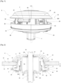
- FIG. figure 1 It was represented at the figure 1 an acoustic partition crossing device 8 intended to be mounted in an orifice 12 provided in a partition 14 of a motor vehicle separating an engine compartment M of the vehicle from a passenger compartment H of the vehicle, as can be seen in FIG. figure 2 .
- the partition 14 may for example be composed of several layers (not shown), such as a layer of sheet metal a layer of soundproofing material, for example foam, which can be arranged on the sheet metal on the side of the passenger compartment H.
- the acoustic partition crossing device 8 comprises a partition crossing ring 10 comprising a body 20 of general revolution shape.
- the body 20 of the ring 10 comprises a channel 22 axially passing through the body 20 for the insertion of a bundle 24 of conductors which passes through the partition 14.
- the body 20 is for example made of rubber or elastomer, but other materials can be envisaged.
- the body 20 is made entirely of elastically deformable material.
- the body 20 comprises a first axial part forming an elastically deformable lip, called acoustic lip 26, and a second part 28 of the body 20 carrying support means 30 cooperating with the partition 14.
- the second part 28 of the body 20 is delimited by an external lateral surface S adjoining an axial surface A of the second part 28 of the body 20 which is opposite the acoustic lip 26.
- the channel 22 connects a first opening 22A made in the acoustic lip 26 to a second opening 22B made in the second part 28 of the body 20.
- the acoustic lip 26 (first part of the body 20) and the second part 28 of the body 20 are here connected by a tubular part 31 delimiting the channel 22.
- the tubular part 31 is substantially cylindrical in revolution.
- the section cross section of the tubular part 31 may vary along its longitudinal axis, for example by having a section locally of a larger diameter between the first 22A and the second opening 22B.
- the second opening 22B is made in a wall of the tubular part 31 forming a deformable bellows 31S.
- the bellows 31S is notably constituted by an extension of the wall of the tubular part 31, extending radially relative to the tubular part 31 towards the channel 22.
- the bellows here comprises two folds, so that the section of the bellows 31S forms an inverted S.
- the bellows 31S may comprise more folds.
- the bellows 31S makes it possible in particular to facilitate the radial deformation of the second part 28 of the body 20 of the ring and thus accompany the movements of the bundle 24, in order to reduce the mechanical stresses on the second part 28 of the body 20.
- the channel 22 is extended by a tube T forming an extension of the bellows 31S.
- the tube T makes it possible to ensure tightening around the bundle 24, and thus obtain a seal against water and noise.
- the tube T also makes it possible to provide mechanical reinforcement and possibly to serve as a support for additional tightening means such as adhesive tape and/or a clamp.
- the tube T has the section of the second opening 22B. To facilitate the maintenance of the bundle 24 in the channel 22, the internal wall of the tube T is corrugated.
- the body 20 is fixed to the partition 14 by pinching the edge B of the partition 14 delimiting the orifice 12 between the acoustic lip 26 and the support means 30.
- the support means 30 cooperate with the external surface 32 of the partition 14 located on the side of the engine compartment M and the acoustic lip 26 cooperates with the external surface 33 of the partition located on the side of the passenger compartment H.
- the acoustic partition crossing device 8 in the orifice 12 in the opposite direction relative to the partition 14, that is to say so that the support means 30 cooperate with the external surface 33 of the partition 14 located on the passenger compartment side H and the acoustic lip 26 cooperates with the external surface 33 of the partition located on the engine compartment side M.
- the nature of the external surfaces 32, 33 (sheet metal, foam, etc.) and the mounting direction required by the automobile manufacturer will be taken into account.
- the support means 30 are here formed by a radial support lip 30 carried by the second part 28 of the body.
- the support lip 30 projects radially from the wall of the tubular part 31.
- the lip makes it possible to match the shape of the partition 14 to ensure good sealing between the passenger compartment H and the engine compartment M. More precisely, in the embodiment illustrated in the figures, and as can be seen in particular in figure 2 , the support lip 30 projects from the external lateral surface S of the body.
- the soundproofing mass housed in the housing volume V1 may be composed exclusively of air, as in the embodiment of the invention illustrated in the figures.
- the soundproofing mass comprises a solid soundproofing material, such as felt or foam.
- the soundproofing mass may comprise mastic such as butyl sealant, which has the advantage of providing a water and noise seal, or an overmolded plastic material such as polyurethane.
- the external lateral surface S of generally annular shape, comprises radial projections 34.
- the radial projections 34 are in the example shown in the figures three in number and distributed uniformly around the circumference of the external lateral surface S (only two are visible in the figure). figure 3 ) Their number and distribution may nevertheless vary.
- the radial projections 34 comprise a substantially flat lower surface oriented towards the second part 28 of the body, for a reason explained later.
- the section of the tubular part 31 is here greater than the dimensions of those of the first 22A and the second opening 22B so that the tubular part 31 delimits a second housing volume V2 of a soundproofing mass.
- the housing volume V2 is composed exclusively of air.
- the soundproofing mass comprises a solid soundproofing material, such as felt, foam.
- the soundproofing mass may comprise mastic such as butyl sealant, which has the advantage of providing a water and noise seal, or an overmolded plastic material such as polyurethane.
- the second part 28 of the body 20 further comprises an anchoring groove 36 surrounding the channel 22.
- the anchoring groove 36 delimited by a first wall 36P and a second wall 36D, which are here concentric.
- the first wall 36P is an extension of the tubular part 31.
- the anchoring groove 36 is of annular shape.
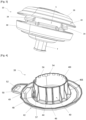
- the acoustic partition crossing device 8 further comprises a mechanical-acoustic washer 39 inserted into the anchoring groove 36 comprising a reinforcing skirt 40 enclosing the first wall 36P and an acoustic collar 42 closing the anchoring groove 36.
- the anchoring groove 36 thus closed by the mechanical-acoustic washer 39 makes it possible to constitute a housing volume V3 of a mass of sound insulation between the body 20 and the mechanical-acoustic washer 39, which further improves the sound insulation performance of the acoustic partition crossing device 8. More precisely, the volume V3 is here delimited by the second 36D wall of the groove, the reinforcing skirt 40 and the acoustic collar 42.
- the housing volume V3 of a sound insulation mass is here filled exclusively with air, but in other variants, the sound insulation mass may comprise mastic such as butyl-type sealing mastic, which has the advantage of providing water and noise sealing, or even an overmolded plastic material such as polyurethane.
- mastic such as butyl-type sealing mastic, which has the advantage of providing water and noise sealing, or even an overmolded plastic material such as polyurethane.
- the reinforcing skirt 40 is cylindrical in revolution. This makes it possible in particular to match the shape of the tubular part 31.
- the reinforcing skirt 40 comprises a plurality of reinforcing ribs 44.
- the reinforcing ribs 44 protrude from the outer surface 40E of the reinforcing skirt, here locally normal to the outer surface 40E.
- the number of reinforcing ribs 44 is adapted according to the dimensions of the reinforcing skirt 44. They can for example be distributed uniformly on the outer surface 40E of the reinforcing skirt.
- the volume V3 is here more precisely delimited by the second wall 36D of the groove, the external surface 40E of the reinforcing skirt, the reinforcing ribs 44 and the acoustic collar 42.
- the reinforcing ribs 44 are all identical, but their dimensions and shape may differ from one to the other.
- the reinforcing ribs 44 are substantially flat and have a square shape whose base projects from the acoustic collar 42 and whose apex joins the external surface 40E of the reinforcing skirt.
- the reinforcing ribs 44 extend over only a portion of the height of the reinforcing skirt 40, here approximately up to mid-height of the reinforcing skirt 40.
- the shape of the reinforcing ribs 44 shown in the figure 4 may naturally vary. For example, it will be possible to provide reinforcing ribs 44 of rectangular and constant section over the entire height of the reinforcing skirt 44.
- the acoustic collar 42 comprises a substantially flat annular section 46.
- the acoustic collar 42 at least partially matches the support lip 30.
- the annular section 46 which flares out to form an edge 48 which at least partially matches the support lip 30.
- the border 48 further comprises a through opening 49 of oblong shape. As can be seen in the figure 6 , this through opening 49 makes it possible to accommodate a boss 28B projecting from the second part 28 of the body of the ring 10. The insertion of the boss 28B into the through opening 49 makes it possible to prevent the rotation of the mechanical-acoustic washer 39 relative to the ring 10.
- the edge 48 also comprises an ear 50 also provided with a through opening 52 of oblong shape. The through opening 52 makes it possible to accommodate a stud (not shown) welded to the vehicle (not shown), to prevent the rotation of the acoustic device 8 for crossing the partition relative to the vehicle.
- the reinforcing skirt 40 further comprises means 54 for clamping the reinforcing skirt 40 around the channel 22, in this case on the first wall 36P of the second part 28 of the body of the ring.
- means 54 for clamping the reinforcing skirt 40 around the channel 22, in this case on the first wall 36P of the second part 28 of the body of the ring are, for example, a plurality of elastically deformable snap-on lugs 56 projecting from an internal surface 40I of the reinforcing skirt.
- the snap-on lugs 56 are, for example, uniformly distributed over the circumference of the internal surface 40I. Their number and dimensions may vary.
- the mechanical-acoustic washer 39 is here made in two parts 39A, 39B assembled by assembly means 57. In a variant not shown, it can be made in one piece.
- the two parts 39A, 39B are separated by a plane passing through the center of the reinforcing skirt 40 and the acoustic collar 42.
- Each of the parts 39A, 39B therefore comprises a part of the reinforcing skirt 40 of substantially semi-cylindrical shape and a part of the acoustic collar 42 of substantially semi-circular shape.
- the through opening 49 and the ear 50 are carried by the part 39B.
- the through opening 49 and the ear 50 are carried by the part 39A, or that they are each carried by a different part 59A, 59B.
- the means for assembling the two parts 39A, 39B are snap-fastening means 57.
- part 39A carries a clip 57C and the part 39B carries a loop 57B, which is inserted into the loop 57C to connect the two parts 39A, 39B.
- the clip 57C is preferably here provided with an elastic lug 57E, the deformation of which when passing the loop 57C during insertion makes it possible to lock the clip 57C in the loop 57C and therefore the assembly of the two parts 39A, 39B.
- each part 39A, 39B comprises respectively two clips 57C and two loops 57C.
- the secondary assembly means 58 are composed of a tab 58L, for example carried by the part 39A, projecting from the edge of the acoustic collar 42 of the part 39A, which is inserted into a corresponding opening 58O made in the edge of the acoustic collar 42 of the part 39B.
- the tab 58L is here provided with an elastic lug 58E whose deformation when passing through the opening 58O during insertion makes it possible to lock the tab 58L in the opening 59O and therefore improve the securing of the two parts 39A, 39B.
- each part 39A, 39B comprises respectively two tab clips 58L and two openings 58O.
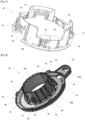
- the acoustic partition crossing device 8 further comprises a retaining collar 60, gripping the external lateral surface S of the second part 28 of the body 20 of the ring 10.
- the retaining collar 60 is here of generally annular shape, in order to better match the shape of the external lateral surface S of the second part 28 of the body 20 of the ring 10, and in particular of the support lip 30.
- the retaining collar 60 cooperates with the edge B of the partition delimiting the orifice 12. It thus makes it possible to guarantee the positioning and retention of the ring 10 in the orifice 12.
- the retaining collar 60 comprises snap-fastening tabs 62 projecting from an external surface 60E of the retaining collar.
- the snap-fastening tabs 62 elastically deformable, cooperate with the edge B of the partition delimiting the orifice 12.
- the snap-in tabs 62 are made in windows 64 made in the wall of the retaining collar 60. These windows 64 and the snap-in tabs 62 are here distributed uniformly over the circumference of the retaining collar 60 and there are three of them. This distribution and this number can nevertheless vary.
- the retaining collar 60 comprises a peripheral rim 66 cooperating with the partition 14, here with the external surface 32 of the partition.
- the peripheral rim 66 is interrupted three times and formed by the union of three arc sections.
- the retaining collar 60 is also provided with support lugs 68 projecting radially from an inner surface 60I of the retaining collar.
- the support lugs 68 cooperate with the radial projections 34 of the outer lateral surface S of the second part 28 of the body of the ring. More precisely, the radial projections 34 rest on the support lugs 68, in particular with the flat lower surface of the radial projections 34, the support lugs 68 having a flat upper surface.
- the number and position of the support lugs 68 is adapted to the number of radial projections 34 and vice versa.
- the holding collar 60 is provided with three support lugs 68 distributed uniformly over the circumference of the holding collar 60.
- the acoustic collar 42 of the mechanical-acoustic washer 39 comprises one or more retaining ribs 70 so as to improve the retention of the lip 30 on the partition 14.
- the retaining rib(s) 70 project from the edge 48 of the acoustic collar 42 in the direction of the lip 30, for example in a manner substantially perpendicular to the plane in which the annular section 46 extends.
- these retaining ribs 70 are distributed uniformly around the periphery of the acoustic collar 42.
- there are eight retaining ribs 70 (only six are visible in the figure, the other two being hidden behind the reinforcing skirt 40).
- the ear 50 of the edge 48 of the acoustic collar 42 is provided on a portion of its periphery with a rim 50R projecting from one of its faces, here from the face opposite the reinforcing skirt 40.
- the rim 50R preferably extends perpendicularly to the face of the ear 50 in a direction opposite to that of the reinforcing skirt 40.
- the rim 50R helps to orient the mechanical-acoustic washer 39 by cooperating with a corresponding part of the partition 14.
- the mechanical-acoustic washer 39 may comprise one or more retaining ribs 70 while the ear 50 will not comprise a rim 50R and vice versa.
- the invention is not limited to the embodiments presented and other embodiments will become clear to those skilled in the art. It is in particular possible for the acoustic partition crossing device to be provided with the ring and the mechanical-acoustic washer without a retaining collar.
Landscapes
- Engineering & Computer Science (AREA)
- Mechanical Engineering (AREA)
- Road Paving Structures (AREA)
- Vehicle Interior And Exterior Ornaments, Soundproofing, And Insulation (AREA)
- Body Structure For Vehicles (AREA)
Claims (15)
- Akustische Trennwanddurchführungsvorrichtung (8), die dazu bestimmt ist, in einer Öffnung (12) montiert zu werden, die in einer Trennwand (14) eines Kraftfahrzeugs ausgebildet ist, die einen Motorraum (M) des Fahrzeugs von einem Fahrgastraum (H) des Fahrzeugs trennt, umfassend einen Ring (10) zur Trennwanddurchführung, der einen Körper (20) aufweist, der umfasst- einen Kanal (22), der den Körper (20) durchquert, um ein Bündel (24) von Leitern einzuführen,- einen ersten Teil, der eine elastisch verformbare Lippe, die sogenannte akustische Lippe (26), bildet, und- ein zweiter Teil (28), der Stützmittel (30) trägt, die dazu bestimmt sind, mit einer Oberfläche (32) der Trennwand zusammenzuwirken,wobei der Körper (20) an der Trennwand (14) befestigt wird, indem der Rand (B) der Trennwand (14), der die Öffnung (12) der Trennwand begrenzt, zwischen der akustischen Lippe (26) und den Stützmitteln (30) eingeklemmt wird,wobei der zweite Teil (28) des Körpers durch eine äußere Seitenfläche (S) begrenzt ist, die an eine axiale Fläche (A) des zweiten Teils (28) des Körpers anschließt, die der akustischen Lippe (26) gegenüberliegt, so dass zwischen dieser axialen Fläche (A) und dieser akustischen Lippe (26) ein erstes Aufnahmevolumen (V1) einer schallisolierenden Masse begrenzt wird,dadurch gekennzeichnet, dass sie weiterhin eine mechanisch-akustische Unterlegscheibe (39) umfasst, umfassend :- eine Verstärkungsschürze (40), die in eine Verankerungsnut (36) eingesetzt ist, die im zweiten Teil (28) ausgebildet ist und den Kanal (22) umgibt,
und- einen akustischen Kragen (42), der die Verankerungsnut (36) schließt und ein Aufnahmevolumen (V3) für eine schallisolierende Masse zwischen dem Körper (20) und der mechanisch-akustischen Unterlegscheibe (39) schafft. - Akustische Trennwanddurchführungsvorrichtung (8) nach Anspruch 1, bei der die mechanisch-akustische Unterlegscheibe (39) durch zwei Teile (39A, 39B) realisiert ist, die durch Montagemittel, z. B. Einrastmittel (57), die von jedem der beiden Teile (39A, 39B) getragen werden, zusammengefügt werden.
- Akustische Trennwanddurchführungsvorrichtung (8) nach einem der vorstehenden Ansprüche, wobei die Stützmittel (30) eine radiale Stützlippe sind, die von dem zweiten Teil (28) des Körpers getragen wird.
- Akustische Trennwanddurchführungsvorrichtung (8) nach Anspruch 3, wobei sich der akustische Kragen (42) zumindest teilweise an die Stützlippe (30) anpasst.
- Akustische Trennwanddurchführungsvorrichtung (8) nach einem der vorstehenden Ansprüche, wobei der erste Teil (26) und der zweite Teil (28) des Körpers durch einen rohrförmigen Teil (31) verbunden sind, der den Kanal (22) begrenzt.
- Akustische Trennwanddurchführungsvorrichtung (8) nach Anspruch 5, bei der die Verankerungsnut (36) von einer ersten Wand (36P) und einer zweiten Wand (36D) begrenzt wird, wobei die erste Wand (36P) eine Verlängerung des rohrförmigen Teils (31) ist.
- Akustische Trennwanddurchführungsvorrichtung (8) nach Anspruch 5 oder 6, wobei der Kanal (22) eine erste Öffnung (22A), die in der akustischen Lippe (26) ausgebildet ist, mit einer zweiten Öffnung (22B) verbindet, die in dem zweiten Teil (28) ausgebildet ist, wobei der Querschnitt des rohrförmigen Teils (31) größer ist als der der ersten (22A) und zweiten (22B) Öffnung, so dass der rohrförmige Teil (31) ein zweites Aufnahmevolumen (V2) für eine schallisolierende Masse begrenzt.
- Akustische Trennwanddurchführungsvorrichtung (8) nach einem der Ansprüche 5 bis 7, wobei der Kanal (22) eine erste Öffnung (22A), die in der akustischen Lippe (26) ausgebildet ist, mit einer zweiten Öffnung (22B) verbindet, die in dem zweiten Teil (28) ausgebildet ist, wobei die zweite Öffnung (22B) in einer Wand des rohrförmigen Teils (31) ausgebildet ist, der einen verformbaren Balg (31S) bildet.
- Akustische Trennwanddurchführungsvorrichtung (8) nach einem der vorstehenden Ansprüche, bei der die Verstärkungsschürze (40) rotationszylindrisch ist.
- Akustische Trennwanddurchführungsvorrichtung (8) nach einem der vorstehenden Ansprüche, wobei die Verstärkungsschürze (40) eine Vielzahl von Verstärkungsrippen (44) umfasst, wobei die Verstärkungsrippen (44) vorzugsweise von einer Außenfläche (40E) der Verstärkungsschürze vorstehen, beispielsweise lokal normal zu der Außenfläche (40E).
- Akustische Trennwanddurchführungsvorrichtung (8) nach einem der vorstehenden Ansprüche, wobei die Verstärkungsschürze (40) Mittel zum Festklemmen (54) der Verstärkungsschürze (40) um den Kanal (22) umfasst, beispielsweise eine Vielzahl von Rastnasen (56), die von einer Innenfläche (40E) der Verstärkungsschürze aus vorstehen.
- Akustische Trennwanddurchführungsvorrichtung (8) nach einem der vorstehenden Ansprüche, die außerdem einen z. B. allgemein ringförmigen Haltekragen (60) umfasst, der die äußere Seitenfläche (S) des zweiten Teils (28) des Körpers umschließt und dazu bestimmt ist, mit einem Rand der Trennwand (14) zusammenzuwirken.
- Akustische Trennwanddurchführungsvorrichtung (8) nach Anspruch 12, wobei der Haltekragen (60) einen Umfangsrand (66) aufweist, der dazu bestimmt ist, mit der Trennwand (14) zusammenzuwirken.
- Akustische Trennwanddurchführungsvorrichtung (8) nach Anspruch 12 oder 13, bei der der Haltekragen (60) Rastnasen (62) umfasst, die von einer Außenfläche (60E) des Haltekragens vorstehen und dazu bestimmt sind, mit einem Rand der die Öffnung (12) begrenzenden Trennwand (14) zusammenzuwirken.
- Akustische Trennwanddurchführungsvorrichtung (8) nach einem der Ansprüche 12 bis 14, wobei der Haltekragen (60) Stütznasen (68) umfasst, die radial von einer Innenfläche (601) des Haltekragens vorstehen und mit der äußeren Seitenfläche (S) des zweiten Teils (28) des Körpers zusammenwirken, vorzugsweise mit radialen Vorsprüngen (34) der äußeren Seitenfläche (S).
Applications Claiming Priority (1)
| Application Number | Priority Date | Filing Date | Title |
|---|---|---|---|
| FR2101701A FR3120033B1 (fr) | 2021-02-22 | 2021-02-22 | Dispositif acoustique de traversée de cloison amélioré |
Publications (3)
| Publication Number | Publication Date |
|---|---|
| EP4046876A1 EP4046876A1 (de) | 2022-08-24 |
| EP4046876C0 EP4046876C0 (de) | 2024-11-20 |
| EP4046876B1 true EP4046876B1 (de) | 2024-11-20 |
Family
ID=75278248
Family Applications (1)
| Application Number | Title | Priority Date | Filing Date |
|---|---|---|---|
| EP22157263.9A Active EP4046876B1 (de) | 2021-02-22 | 2022-02-17 | Akustische vorrichtung zur wanddurchführung |
Country Status (2)
| Country | Link |
|---|---|
| EP (1) | EP4046876B1 (de) |
| FR (1) | FR3120033B1 (de) |
Families Citing this family (2)
| Publication number | Priority date | Publication date | Assignee | Title |
|---|---|---|---|---|
| CA3233123A1 (en) | 2021-09-30 | 2023-04-06 | JR. Jack F. KING | Side wall seal for piping |
| FR3145716A1 (fr) * | 2023-02-09 | 2024-08-16 | Psa Automobiles Sa | Arrangement pour passage étanche d’un faisceau électrique |
Family Cites Families (6)
| Publication number | Priority date | Publication date | Assignee | Title |
|---|---|---|---|---|
| FR2809877B1 (fr) * | 2000-05-30 | 2002-10-25 | Peugeot Citroen Automobiles Sa | Dispositif de traversee etanche d'un faisceau electrique par une ouverture de passage a travers un tablier d'un vehicule automobile et procede de montage du faisceau dans l'ouverture |
| FR2826091B1 (fr) * | 2001-06-14 | 2003-08-29 | C F Gomma Barre Thomas | Piece d'etancheite pour la traversee d'un faisceau electrique a travers l'ouverture d'une paroi |
| FR2878601B1 (fr) * | 2004-12-01 | 2007-03-09 | Valeo Electronique Sys Liaison | Bague de traversee de cloison |
| FR2884891B1 (fr) * | 2005-04-26 | 2011-03-18 | Caoutchoucs Modernes | Procede de fabrication d'une piece de traversee d'un faisceau de cables electriques dans un tablier de vehicule automobile, et piece de traversee ainsi fabriquee. |
| JP5157513B2 (ja) * | 2008-02-20 | 2013-03-06 | 住友電装株式会社 | グロメット |
| FR3019392B1 (fr) * | 2014-03-27 | 2017-09-15 | Renault Sas | Dispositif de traversee etanche de faisceau electrique |
-
2021
- 2021-02-22 FR FR2101701A patent/FR3120033B1/fr active Active
-
2022
- 2022-02-17 EP EP22157263.9A patent/EP4046876B1/de active Active
Also Published As
| Publication number | Publication date |
|---|---|
| EP4046876A1 (de) | 2022-08-24 |
| EP4046876C0 (de) | 2024-11-20 |
| FR3120033B1 (fr) | 2023-08-04 |
| FR3120033A1 (fr) | 2022-08-26 |
Similar Documents
| Publication | Publication Date | Title |
|---|---|---|
| EP4046876B1 (de) | Akustische vorrichtung zur wanddurchführung | |
| EP0781692B1 (de) | Scheibenwischer-Mechanismus mit Führungs-und Dichtungsmittel zur Antriebaxen-Durchquerung eines Bleches | |
| FR2901858A1 (fr) | Support pour tube ondule | |
| EP1463904B1 (de) | Durch überlappen wiederverschliessbare schutzhülle und verwendung davon | |
| EP0354082A1 (de) | Führungskulisse für bewegliche Fensterscheiben, insbesondere für Automobilfensterscheiben | |
| FR2853606A1 (fr) | Procede et agencement pour l'assemblage par succession de deux mouvements selon une direction longitudinale | |
| EP0970853B1 (de) | Dichte Durchlassvorrichtung eines elektrischen Kabelbaumes durch die Durchführungsöffunug einer Fahrzeugspritzwand und Montageverfahren des elektrischen Kabelbaumes | |
| FR2862430A1 (fr) | Structure de fixation de batterie d'accumulateurs pour vehicule | |
| EP4098492B1 (de) | Schottdurchführung für mindestens ein kabel und/oder mindestens ein rohr zum durchführen durch eine wand | |
| FR2818816A1 (fr) | Dispositif pour envelopper et fixer un faisceau de cables electriques | |
| EP3599404A1 (de) | Regulierbare befestigungshalterung für die montage eines rohrförmigen artikels auf einem externen organ | |
| FR2703753A1 (fr) | Presse-étoupe à montage rapide. | |
| FR2799694A1 (fr) | Dispositif de support superieur pour ressort de suspension, notamment automobile | |
| FR2744781A1 (fr) | Dispositif d'obturation d'une ouverture et en particulier d'une ouverture traversant une paroi d'un vehicule automobile | |
| EP0706915B1 (de) | Montage-Einrichtung für ein Bündel elektrischer Leiter | |
| FR2695973A1 (fr) | Dispositif de guidage pour tige d'amortisseur. | |
| EP0023183A1 (de) | Vorrichtung zur Fernsteuerung mittels Kabel und mit dieser Vorrichtung ausgerüstetes Fahrzeug | |
| FR2826091A1 (fr) | Piece d'etancheite pour la traversee d'un faisceau electrique a travers l'ouverture d'une paroi | |
| EP0686780B1 (de) | Anschlussteil für Betätigungskabel | |
| EP0891897A1 (de) | Flexible Schutzhülle zur SIcherung der Durchfuhr eines elektrischen Kabelbundes zwischen zwei Teilen einer Installation wie einem Kraftfahrzeug | |
| FR2920114A1 (fr) | Partie structurelle de porte de vehicule automobile munie d'une feuille d'etancheite | |
| EP1607271B1 (de) | Durchführungsvorrichtung für dünnes Blech | |
| FR2584476A1 (fr) | Raccord de conduit | |
| EP4033198B1 (de) | Verbindungsvorrichtung zwischen einem zündmittel einer treibladung und einer verbrennbaren hülse einer munition, verbrennbare hülse und elastische unterlegscheibe, die mit einer solchen verbindungsvorrichtung zusammenwirken | |
| FR3075896A1 (fr) | Ensemble pour la fixation d'un cable de boite de vitesses |
Legal Events
| Date | Code | Title | Description |
|---|---|---|---|
| PUAI | Public reference made under article 153(3) epc to a published international application that has entered the european phase |
Free format text: ORIGINAL CODE: 0009012 |
|
| STAA | Information on the status of an ep patent application or granted ep patent |
Free format text: STATUS: THE APPLICATION HAS BEEN PUBLISHED |
|
| AK | Designated contracting states |
Kind code of ref document: A1 Designated state(s): AL AT BE BG CH CY CZ DE DK EE ES FI FR GB GR HR HU IE IS IT LI LT LU LV MC MK MT NL NO PL PT RO RS SE SI SK SM TR |
|
| STAA | Information on the status of an ep patent application or granted ep patent |
Free format text: STATUS: REQUEST FOR EXAMINATION WAS MADE |
|
| 17P | Request for examination filed |
Effective date: 20230124 |
|
| RBV | Designated contracting states (corrected) |
Designated state(s): AL AT BE BG CH CY CZ DE DK EE ES FI FR GB GR HR HU IE IS IT LI LT LU LV MC MK MT NL NO PL PT RO RS SE SI SK SM TR |
|
| RIC1 | Information provided on ipc code assigned before grant |
Ipc: B60R 16/02 20060101AFI20240731BHEP |
|
| GRAP | Despatch of communication of intention to grant a patent |
Free format text: ORIGINAL CODE: EPIDOSNIGR1 |
|
| STAA | Information on the status of an ep patent application or granted ep patent |
Free format text: STATUS: GRANT OF PATENT IS INTENDED |
|
| GRAS | Grant fee paid |
Free format text: ORIGINAL CODE: EPIDOSNIGR3 |
|
| INTG | Intention to grant announced |
Effective date: 20240913 |
|
| GRAA | (expected) grant |
Free format text: ORIGINAL CODE: 0009210 |
|
| STAA | Information on the status of an ep patent application or granted ep patent |
Free format text: STATUS: THE PATENT HAS BEEN GRANTED |
|
| AK | Designated contracting states |
Kind code of ref document: B1 Designated state(s): AL AT BE BG CH CY CZ DE DK EE ES FI FR GB GR HR HU IE IS IT LI LT LU LV MC MK MT NL NO PL PT RO RS SE SI SK SM TR |
|
| REG | Reference to a national code |
Ref country code: GB Ref legal event code: FG4D Free format text: NOT ENGLISH |
|
| REG | Reference to a national code |
Ref country code: CH Ref legal event code: EP |
|
| REG | Reference to a national code |
Ref country code: DE Ref legal event code: R096 Ref document number: 602022007781 Country of ref document: DE |
|
| REG | Reference to a national code |
Ref country code: IE Ref legal event code: FG4D Free format text: LANGUAGE OF EP DOCUMENT: FRENCH |
|
| U01 | Request for unitary effect filed |
Effective date: 20241120 |
|
| U07 | Unitary effect registered |
Designated state(s): AT BE BG DE DK EE FI FR IT LT LU LV MT NL PT RO SE SI Effective date: 20241126 |
|
| U20 | Renewal fee for the european patent with unitary effect paid |
Year of fee payment: 4 Effective date: 20250224 |
|
| PG25 | Lapsed in a contracting state [announced via postgrant information from national office to epo] |
Ref country code: IS Free format text: LAPSE BECAUSE OF FAILURE TO SUBMIT A TRANSLATION OF THE DESCRIPTION OR TO PAY THE FEE WITHIN THE PRESCRIBED TIME-LIMIT Effective date: 20250320 Ref country code: HR Free format text: LAPSE BECAUSE OF FAILURE TO SUBMIT A TRANSLATION OF THE DESCRIPTION OR TO PAY THE FEE WITHIN THE PRESCRIBED TIME-LIMIT Effective date: 20241120 |
|
| PG25 | Lapsed in a contracting state [announced via postgrant information from national office to epo] |
Ref country code: ES Free format text: LAPSE BECAUSE OF FAILURE TO SUBMIT A TRANSLATION OF THE DESCRIPTION OR TO PAY THE FEE WITHIN THE PRESCRIBED TIME-LIMIT Effective date: 20241120 |
|
| PG25 | Lapsed in a contracting state [announced via postgrant information from national office to epo] |
Ref country code: NO Free format text: LAPSE BECAUSE OF FAILURE TO SUBMIT A TRANSLATION OF THE DESCRIPTION OR TO PAY THE FEE WITHIN THE PRESCRIBED TIME-LIMIT Effective date: 20250220 |
|
| PG25 | Lapsed in a contracting state [announced via postgrant information from national office to epo] |
Ref country code: GR Free format text: LAPSE BECAUSE OF FAILURE TO SUBMIT A TRANSLATION OF THE DESCRIPTION OR TO PAY THE FEE WITHIN THE PRESCRIBED TIME-LIMIT Effective date: 20250221 |
|
| PG25 | Lapsed in a contracting state [announced via postgrant information from national office to epo] |
Ref country code: PL Free format text: LAPSE BECAUSE OF FAILURE TO SUBMIT A TRANSLATION OF THE DESCRIPTION OR TO PAY THE FEE WITHIN THE PRESCRIBED TIME-LIMIT Effective date: 20241120 |
|
| PG25 | Lapsed in a contracting state [announced via postgrant information from national office to epo] |
Ref country code: RS Free format text: LAPSE BECAUSE OF FAILURE TO SUBMIT A TRANSLATION OF THE DESCRIPTION OR TO PAY THE FEE WITHIN THE PRESCRIBED TIME-LIMIT Effective date: 20250220 |
|
| PG25 | Lapsed in a contracting state [announced via postgrant information from national office to epo] |
Ref country code: SM Free format text: LAPSE BECAUSE OF FAILURE TO SUBMIT A TRANSLATION OF THE DESCRIPTION OR TO PAY THE FEE WITHIN THE PRESCRIBED TIME-LIMIT Effective date: 20241120 |
|
| PG25 | Lapsed in a contracting state [announced via postgrant information from national office to epo] |
Ref country code: SK Free format text: LAPSE BECAUSE OF FAILURE TO SUBMIT A TRANSLATION OF THE DESCRIPTION OR TO PAY THE FEE WITHIN THE PRESCRIBED TIME-LIMIT Effective date: 20241120 |
|
| PG25 | Lapsed in a contracting state [announced via postgrant information from national office to epo] |
Ref country code: CZ Free format text: LAPSE BECAUSE OF FAILURE TO SUBMIT A TRANSLATION OF THE DESCRIPTION OR TO PAY THE FEE WITHIN THE PRESCRIBED TIME-LIMIT Effective date: 20241120 |
|
| PG25 | Lapsed in a contracting state [announced via postgrant information from national office to epo] |
Ref country code: MC Free format text: LAPSE BECAUSE OF FAILURE TO SUBMIT A TRANSLATION OF THE DESCRIPTION OR TO PAY THE FEE WITHIN THE PRESCRIBED TIME-LIMIT Effective date: 20241120 |
|
| PLBE | No opposition filed within time limit |
Free format text: ORIGINAL CODE: 0009261 |
|
| STAA | Information on the status of an ep patent application or granted ep patent |
Free format text: STATUS: NO OPPOSITION FILED WITHIN TIME LIMIT |
|
| REG | Reference to a national code |
Ref country code: CH Ref legal event code: PL |
|
| PG25 | Lapsed in a contracting state [announced via postgrant information from national office to epo] |
Ref country code: CH Free format text: LAPSE BECAUSE OF NON-PAYMENT OF DUE FEES Effective date: 20250228 |
|
| 26N | No opposition filed |
Effective date: 20250821 |
|
| PG25 | Lapsed in a contracting state [announced via postgrant information from national office to epo] |
Ref country code: IE Free format text: LAPSE BECAUSE OF NON-PAYMENT OF DUE FEES Effective date: 20250217 |
|
| U20 | Renewal fee for the european patent with unitary effect paid |
Year of fee payment: 5 Effective date: 20260224 |
|
| PGFP | Annual fee paid to national office [announced via postgrant information from national office to epo] |
Ref country code: GB Payment date: 20260219 Year of fee payment: 5 |