EP4046876A1 - Akustische vorrichtung zur wanddurchführung - Google Patents
Akustische vorrichtung zur wanddurchführung Download PDFInfo
- Publication number
- EP4046876A1 EP4046876A1 EP22157263.9A EP22157263A EP4046876A1 EP 4046876 A1 EP4046876 A1 EP 4046876A1 EP 22157263 A EP22157263 A EP 22157263A EP 4046876 A1 EP4046876 A1 EP 4046876A1
- Authority
- EP
- European Patent Office
- Prior art keywords
- acoustic
- partition
- lip
- bulkhead
- channel
- Prior art date
- Legal status (The legal status is an assumption and is not a legal conclusion. Google has not performed a legal analysis and makes no representation as to the accuracy of the status listed.)
- Granted
Links
Images


Classifications
-
- B—PERFORMING OPERATIONS; TRANSPORTING
- B60—VEHICLES IN GENERAL
- B60R—VEHICLES, VEHICLE FITTINGS, OR VEHICLE PARTS, NOT OTHERWISE PROVIDED FOR
- B60R16/00—Electric or fluid circuits specially adapted for vehicles and not otherwise provided for; Arrangement of elements of electric or fluid circuits specially adapted for vehicles and not otherwise provided for
- B60R16/02—Electric or fluid circuits specially adapted for vehicles and not otherwise provided for; Arrangement of elements of electric or fluid circuits specially adapted for vehicles and not otherwise provided for electric constitutive elements
- B60R16/0207—Wire harnesses
- B60R16/0215—Protecting, fastening and routing means therefor
- B60R16/0222—Grommets
Definitions
- the invention relates to the field of guiding bundles of electrical conductors in a motor vehicle.
- It relates more particularly to a crossing ring, by a bundle of conductors, of a partition of a motor vehicle.
- these bundles of conductors are passed through the channel of a bulkhead crossing ring which is intended to be inserted into an orifice made in the bulkhead separating the passenger compartment from the engine compartment.
- a bulkhead penetration ring is generally designed in such a way as to limit the transmission of noise from the engine compartment to the passenger compartment.
- a bulkhead crossing ring comprising a body comprising a channel passing through the body for the insertion of a bundle of conductors, a first part forming an elastically deformable lip, and a second part bearing support means intended to cooperate with a edge of the orifice, the body being fixed on the partition by pinching the edge of the partition delimiting the orifice between the acoustic lip and the bearing means.
- the second part of the body is delimited by an external lateral surface contiguous with an axial surface of the second part of the body which faces the acoustic lip, so as to delimit between this axial surface and this acoustic lip a first housing volume of a mass of sound insulation.
- this bulkhead crossing ring offers good sound insulation performance while being inexpensive to manufacture, it has the disadvantage of being subject to significant deformations once placed in the hole in the bulkhead of the vehicle, in particular when it is made of elastomeric or rubber-based material.
- the object of the invention is in particular to provide an acoustic device for partition crossing which is more mechanically resistant, and which thus retains good sound insulation performance despite the stresses to which the partition crossing ring is subjected.
- the bulkhead crossing ring is stiffened and can therefore be made of elastomeric or rubber-based material without risking that it undergoes significant deformations after installation in the orifice of the vehicle partition.
- the sound insulation performance of the device is improved. partition crossing acoustics.
- the mechanical-acoustic washer is made in two parts assembled by assembly means, for example snap-fastening means carried by each of the two parts.
- assembly means for example snap-fastening means carried by each of the two parts.
- This configuration is all the more advantageous when the bundle has section variations along its axis, or has bends.
- the bearing means are a radial bearing lip carried by the second part of the body.
- the acoustic collar In order to obtain a better mechanical resistance of the ring, the acoustic collar at least partially hugs the support lip.
- the first part and the second part of the body are connected by a tubular part delimiting the channel.
- the anchoring groove is delimited by a first wall and a second wall, the first wall being an extension of the tubular part.
- the channel connects a first opening made in the acoustic lip to a second opening made in the second part, the section of the tubular part being greater than those of the first and the second opening so that the tubular part delimits a second housing volume of a soundproofing mass. It also makes it possible to adapt to the different sizes and geometries of bundles inserted in the channel of the body of the ring.
- the channel connects a first opening made in the acoustic lip to a second opening made in the second part, and the second opening is made in a wall of the tubular part forming a bellows deformable.
- one end of the channel is sufficiently flexible to adapt to a possible bend or elbow of the cable harness, which makes it possible to minimize the stresses on the ring due to the configuration of the harness.
- the reinforcing skirt is cylindrical of revolution.
- the reinforcing skirt comprises a plurality of reinforcing ribs.
- the reinforcing ribs protrude from an outer surface of the reinforcing skirt, for example locally from normal to the outer surface.
- the reinforcing skirt comprises means for tightening the reinforcing skirt around the channel, for example a plurality of lugs snap projecting from an inner surface of the reinforcing skirt.
- a retaining collar for example of generally annular shape, enclosing the external lateral surface of the second part of the body and intended to cooperate an edge of the partition.
- the retaining collar contributes to the stiffening of the device.
- the retaining collar comprises a peripheral edge intended to cooperate with the partition.
- the retaining collar comprises snap-fastening lugs projecting from an outer surface of the retaining collar, intended to cooperate with a edge of the partition delimiting the orifice.
- the retaining collar comprises support lugs projecting radially from an internal surface of the retaining collar, cooperating with the outer side surface of the second body part, preferably with radial projections of the outer side surface.
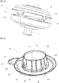
- FIG. 1 We represented at the figure 1 an acoustic partition crossing device 8 intended to be mounted in an orifice 12 provided in a partition 14 of a motor vehicle separating an engine compartment M of the vehicle from a passenger compartment H of the vehicle, as can be seen in figure 2 .
- the partition 14 can for example be composed of several layers (not shown), such as a layer of sheet metal a layer of soundproofing material, for example foam, which can be placed on the sheet metal on the side of the passenger compartment H.
- a layer of sheet metal a layer of soundproofing material, for example foam, which can be placed on the sheet metal on the side of the passenger compartment H.
- the acoustic device 8 for crossing the partition comprises a ring 10 for crossing the partition comprising a body 20 of general shape of revolution.
- the body 20 of the ring 10 comprises a channel 22 passing axially through the body 20 for the insertion of a bundle 24 of conductors which passes through the partition 14.
- the body 20 is for example made of rubber or elastomer, but of other materials can be considered.
- the body 20 is made entirely of elastically deformable material.
- the body 20 comprises a first axial part forming an elastically deformable lip, called the acoustic lip 26, and a second part 28 of the body 20 carrying support means 30 cooperating with the partition 14.
- the second part 28 of the body 20 is delimited by an outer lateral surface S contiguous with an axial surface A of the second part 28 of the body 20 which faces the acoustic lip 26
- the channel 22 connects a first opening 22A made in the acoustic lip 26 to a second opening 22B made in the second part 28 of the body 20.
- the acoustic lip 26 (first part of the body 20) and the second part 28 of the body 20 are here connected by a tubular part 31 delimiting the channel 22.
- the tubular part 31 is substantially cylindrical of revolution.
- the section transverse of the tubular part 31 may vary along its longitudinal axis, for example by having a section locally of a larger diameter between the first 22A and the second opening 22B.
- the second opening 22B is made in a wall of the tubular part 31 forming a deformable bellows 31S.
- the bellows 31S consists in particular of an extension of the wall of the tubular part 31, extending radially with respect to the tubular part 31 towards the channel 22.
- the bellows here comprises two folds, so that the section of the bellows 31S forms an inverted S.
- the bellows 31S may include more folds.
- the bellows 31S makes it possible in particular to facilitate the radial deformation of the second part 28 of the body 20 of the ring and thus accompany the movements of the bundle 24, in order to reduce the mechanical stresses on the second part 28 of the body 20.
- the channel 22 is extended by a tube T forming an extension of the bellows 31S.
- the tube T makes it possible to ensure tightness around the beam 24, and thus to obtain water and noise tightness.
- the tube T also serves to provide mechanical reinforcement and possibly to serve as a support for complementary clamping means such as adhesive tape and/or clamping collar.
- the section of the tube T is the section of the second opening 22B.
- the internal wall of the tube T is corrugated.
- the body 20 is fixed to the partition 14 by pinching the edge B of the partition 14 delimiting the orifice 12 between the acoustic lip 26 and the support means 30.
- the bearing means 30 cooperate with the outer surface 32 of the partition 14 located on the side of the engine compartment M and the acoustic lip 26 cooperates with the outer surface 33 of the partition located on the side of the passenger compartment. H.
- the acoustic device 8 for crossing the partition in the orifice 12 in the opposite direction with respect to the partition 14, that is to say so that the support means 30 cooperate with the external surface 33 of the partition 14 located on the side of the passenger compartment H and the acoustic lip 26 cooperates with the external surface 33 of the partition located on the side of the engine compartment M.
- the support means 30 cooperate with the external surface 33 of the partition 14 located on the side of the passenger compartment H
- the acoustic lip 26 cooperates with the external surface 33 of the partition located on the side of the engine compartment M.
- account will be taken of the nature external surfaces 32, 33 (sheet metal, foam, etc.) and the mounting direction required by the car manufacturer.
- the support means 30 are here formed by a radial support lip 30 carried by the second part 28 of the body.
- the bearing lip 30 projects radially from the wall of the tubular part 31.
- the lip makes it possible to match the shape of the partition 14 to ensure good sealing between the passenger compartment H and the engine compartment M. More precisely, in the embodiment illustrated in the figures, and as can be seen in particular at picture 2 , the bearing lip 30 protrudes from the outer side surface S of the body.
- the soundproofing mass comprises a solid soundproofing material, such as felt or foam.
- the soundproofing mass may comprise mastic such as sealing mastic of the butyl type, which has the advantage of conferring water and noise tightness, or else a plastic material molded such as polyurethane.
- the external lateral surface S of generally annular shape, comprises radial projections 34.
- the radial projections 34 are in the example shown in the figures three in number and distributed uniformly over the circumference of the external lateral surface S (only two are visible at the picture 3 ) Their number and distribution may nevertheless vary.
- Radial projections 34 include a substantially planar bottom surface facing second body portion 28, for a reason explained below.
- the soundproofing mass comprises a solid soundproofing material, such as felt, foam.
- the soundproofing mass may comprise mastic such as sealing mastic of the butyl type, which has the advantage of conferring water and noise tightness, or else a plastic material molded such as polyurethane.
- the second part 28 of the body 20 further comprises an anchoring groove 36 surrounding the channel 22.
- the anchoring groove 36 delimited by a first wall 36P and a second wall 36D, which are here concentric.
- the first wall 36P is an extension of the tubular part 31.
- the anchoring groove 36 is of annular shape.
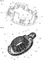
- the acoustic device 8 for crossing the partition further comprises a mechanical-acoustic washer 39 inserted in the anchoring groove 36 comprising a reinforcing skirt 40 enclosing the first wall 36P and an acoustic collar 42 closing the anchoring groove 36.
- the anchoring groove 36 thus closed by the mechanical-acoustic washer 39 makes it possible to form a housing volume V3 of a mass of sound insulation between the body 20 and the mechanical-acoustic washer 39, which further improves the performance. sound insulation of the acoustic device 8 through the partition. More precisely, the volume V3 is here delimited by the second wall 36D of the groove, the reinforcing skirt 40 and the acoustic collar 42.
- the housing volume V3 of a mass of sound insulation is here filled exclusively with air, but in other variants, the sound insulation mass may comprise mastic such as sealing mastic of the butyl type, which has the advantage of imparting sealing against water and noise, or even an overmolded plastic material such as polyurethane.
- the reinforcing skirt 40 is cylindrical of revolution. This makes it possible in particular to match the shape of the tubular part 31.
- the reinforcing skirt 40 comprises a plurality of reinforcing ribs 44.
- the reinforcing ribs 44 protrude from the outer surface 40E of the reinforcing skirt, here locally normal to the outer surface 40E.
- the number of reinforcing ribs 44 is adapted according to the dimensions of the reinforcing skirt 44. They can for example be distributed uniformly over the outer surface 40E of the reinforcing skirt.
- the volume V3 is here more precisely delimited by the second wall 36D of the groove, the outer surface 40E of the reinforcing skirt, the reinforcing ribs 44 and the acoustic collar 42.
- the reinforcing ribs 44 are all identical, but their dimensions and shape may differ from one to the other.
- the reinforcing ribs 44 are substantially flat and have a square shape, the base of which projects from the acoustic collar 42 and the top of which joins the outer surface 40E of the reinforcing skirt.
- the reinforcing ribs 44 extend over only a portion of the height of the reinforcing skirt 40, here approximately up to mid-height of the reinforcing skirt 40.
- the shape of the reinforcing ribs 44 shown in figure 4 can of course vary. One could, for example, provide reinforcing ribs 44 of rectangular and constant section over the entire height of the reinforcing skirt 44.
- the acoustic collar 42 comprises a substantially flat annular section 46.
- the acoustic collar 42 at least partially matches the support lip 30.
- the annular section 46 which flares out to form a border 48 which at least partially matches the support lip 30 .
- the border 48 further comprises a through opening 49 of oblong shape. As can be seen at the figure 6 , this through-opening 49 makes it possible to accommodate a boss 28B projecting from the second part 28 of the body of the ring 10. The insertion of the boss 28B in the through-opening 49 makes it possible to prevent rotation of the mechanical washer acoustic 39 relative to the ring 10.
- the border 48 also includes a lug 50 also provided with a through opening 52 of oblong shape. The through opening 52 makes it possible to accommodate a stud (not shown) welded to the vehicle (not shown), to prevent the rotation of the acoustic device 8 passing through the partition with respect to the vehicle.
- the reinforcing skirt 40 further comprises means 54 for tightening the reinforcing skirt 40 around the channel 22, in this case on the first wall 36P of the second part 28 of the body of the ring.
- This is for example a plurality of latching lugs 56, elastically deformable, projecting from an internal surface 40I of the reinforcing skirt.
- the latching lugs 56 are for example distributed uniformly over the circumference of the internal surface 40I. Their number and dimensions may vary.
- the mechanical-acoustic washer 39 is here made in two parts 39A, 39B assembled by assembly means 57. In a variant not shown, it can be made in one piece.
- the two parts 39A, 39B are separated by a plane passing through the center of the reinforcing skirt 40 and of the acoustic collar 42.
- Each of the parts 39A, 39B therefore comprises a part of the skirt reinforcement 40 of substantially semi-cylindrical shape and a part of the acoustic collar 42 of substantially semi-circular shape.
- the through opening 49 and the ear 50 are carried by the part 39B. Provision may however be made for the through-opening 49 and the ear 50 to be carried by the part 39A, or even for each to be carried by a different part 59A, 59B.
- the assembly means of the two parts 39A, 39B are snap-fastening means 57.
- Part 39A carries a clip 57C and part 39B carries a loop 57B, which is inserted into loop 57C to connect the two parts 39A, 39B.
- the clip 57C is preferably provided here with an elastic lug 57E whose deformation on passage of the loop 57C during insertion makes it possible to lock the clip 57C in the loop 57C and therefore the assembly of the two parts 39A, 39B.
- each part 39A, 39B respectively comprises two clips 57C and two loops 57C.
- the secondary assembly means 58 are composed of a tab 58L, for example carried by the part 39A, protruding from the edge of the acoustic collar 42 of the part 39A, which is inserted into a corresponding opening 58O performed in the edge of the acoustic collar 42 of part 39B.
- the tongue 58L is here provided with an elastic lug 58E whose deformation as it passes through the opening 58O during insertion makes it possible to lock the tongue 58L in the opening 59O and therefore improve the joining of the two parts 39A, 39B.
- the secondary assembly means 58 are doubled, that is to say that each part 39A, 39B respectively comprises two tab clips 58L and two openings 58O.
- the acoustic device 8 for crossing the partition further comprises a retaining collar 60, enclosing the outer lateral surface S of the second part 28 of the body 20 of the ring 10.
- the retaining collar 60 is here of generally annular shape, in order to better match the shape of the outer lateral surface S of the second part 28 of the body 20 of the ring 10, and in particular of the bearing lip 30.
- the retaining collar 60 cooperates with the edge B of the partition delimiting the orifice 12. It thus makes it possible to guarantee the positioning and the maintenance of the ring 10 in the orifice 12.
- the retaining collar 60 includes snap tabs 62 projecting from an outer surface 60E of the retaining collar.
- the snap tabs 62 elastically deformable, cooperate with the edge B of the partition delimiting the orifice 12.
- the latching lugs 62 are made in windows 64 formed in the wall of the retaining collar 60. These windows 64 and the latching lugs 62 are here distributed uniformly over the circumference of the retaining collar 60 and three in number . This distribution as well as this number may nevertheless vary.
- the retaining collar 60 comprises a peripheral rim 66 cooperating with the partition 14, here with the outer surface 32 of the partition.
- the peripheral rim 66 is interrupted three times and formed by the joining of three arc sections.
- an annular peripheral rim 66 uninterrupted on the circumference of the retaining collar 60.
- the retaining collar 60 is also provided with support pegs 68 projecting radially from an internal surface 60I of the retaining collar.
- the support tabs 68 cooperate with the radial projections 34 of the outer side surface S of the second part 28 of the body of the ring. Specifically, radial projections 34 rest on support tabs 68, particularly with the flat bottom surface of radial projections 34, support tabs 68 having a flat top surface.
- the number and position of support tabs 68 is matched to the number of radial projections 34 and vice versa.
- the retaining collar 60 is provided with three support tabs 68 distributed uniformly over the circumference of the retaining collar 60.
- the acoustic collar 42 of the mechanical-acoustic washer 39 comprises one or more holding ribs 70 so as to improve the holding of the lip 30 on the partition 14.
- the holding rib or ribs 70 protrude from the edge 48 of the acoustic collar 42 in the direction of the lip 30, for example substantially perpendicular to the plane in which the annular section 46 extends.
- the retaining ribs 70 are eight in number (only six are visible in the figure, the other two being concealed behind the reinforcing skirt 40).
- the ear 50 of the edge 48 of the acoustic collar 42 is provided on part of its periphery with a rim 50R projecting from one of its faces, here from from the face opposite the reinforcement skirt 40.
- the flange 50R preferably extends perpendicular to the face of the ear 50 in a direction opposite to that of the reinforcement skirt 40.
- the flange 50R makes it possible to assist in the orientation of the mechanical-acoustic washer 39 by cooperating with a corresponding part of the partition 14.
- the mechanical-acoustic washer 39 may include one or more retaining ribs 70 while the lug 50 will not include a rim 50R and vice versa.
- the invention is not limited to the embodiments shown and other embodiments will be apparent to those skilled in the art. It is in particular possible for the acoustic partition crossing device to be fitted with the ring and the mechanical-acoustic washer without a retaining collar.
Landscapes
- Engineering & Computer Science (AREA)
- Mechanical Engineering (AREA)
- Road Paving Structures (AREA)
- Vehicle Interior And Exterior Ornaments, Soundproofing, And Insulation (AREA)
- Body Structure For Vehicles (AREA)
Applications Claiming Priority (1)
| Application Number | Priority Date | Filing Date | Title |
|---|---|---|---|
| FR2101701A FR3120033B1 (fr) | 2021-02-22 | 2021-02-22 | Dispositif acoustique de traversée de cloison amélioré |
Publications (3)
| Publication Number | Publication Date |
|---|---|
| EP4046876A1 true EP4046876A1 (de) | 2022-08-24 |
| EP4046876C0 EP4046876C0 (de) | 2024-11-20 |
| EP4046876B1 EP4046876B1 (de) | 2024-11-20 |
Family
ID=75278248
Family Applications (1)
| Application Number | Title | Priority Date | Filing Date |
|---|---|---|---|
| EP22157263.9A Active EP4046876B1 (de) | 2021-02-22 | 2022-02-17 | Akustische vorrichtung zur wanddurchführung |
Country Status (2)
| Country | Link |
|---|---|
| EP (1) | EP4046876B1 (de) |
| FR (1) | FR3120033B1 (de) |
Cited By (2)
| Publication number | Priority date | Publication date | Assignee | Title |
|---|---|---|---|---|
| FR3145716A1 (fr) * | 2023-02-09 | 2024-08-16 | Psa Automobiles Sa | Arrangement pour passage étanche d’un faisceau électrique |
| EP4409184A4 (de) * | 2021-09-30 | 2025-07-16 | Roof Goose Vent Llc | Seitenwanddichtung für rohrleitungen |
Citations (6)
| Publication number | Priority date | Publication date | Assignee | Title |
|---|---|---|---|---|
| FR2809877A1 (fr) * | 2000-05-30 | 2001-12-07 | Peugeot Citroen Automobiles Sa | Dispositif de traversee etanche d'un faisceau electrique par une ouverture de passage a travers un tablier d'un vehicule automobile et procede de montage du faisceau dans l'ouverture |
| FR2826091A1 (fr) * | 2001-06-14 | 2002-12-20 | C F Gomma Barre Thomas | Piece d'etancheite pour la traversee d'un faisceau electrique a travers l'ouverture d'une paroi |
| FR2878601A1 (fr) * | 2004-12-01 | 2006-06-02 | Valeo Electronique Sys Liaison | Bague de traversee de cloison |
| EP1717502A1 (de) * | 2005-04-26 | 2006-11-02 | Caoutchoucs Modernes | Herstellungsverfahren von einer Durchführung eines elektrischen Kabelstrangs eines Kraftfahrzeuges, sowie Gegenstände die nach diese Verfahren hergestellt werden |
| EP2246950A1 (de) * | 2008-02-20 | 2010-11-03 | Sumitomo Wiring Systems, Ltd. | Öse |
| WO2015145003A1 (fr) * | 2014-03-27 | 2015-10-01 | Renault S.A.S. | Dispositif de traversée étanche de faisceau électrique |
-
2021
- 2021-02-22 FR FR2101701A patent/FR3120033B1/fr active Active
-
2022
- 2022-02-17 EP EP22157263.9A patent/EP4046876B1/de active Active
Patent Citations (6)
| Publication number | Priority date | Publication date | Assignee | Title |
|---|---|---|---|---|
| FR2809877A1 (fr) * | 2000-05-30 | 2001-12-07 | Peugeot Citroen Automobiles Sa | Dispositif de traversee etanche d'un faisceau electrique par une ouverture de passage a travers un tablier d'un vehicule automobile et procede de montage du faisceau dans l'ouverture |
| FR2826091A1 (fr) * | 2001-06-14 | 2002-12-20 | C F Gomma Barre Thomas | Piece d'etancheite pour la traversee d'un faisceau electrique a travers l'ouverture d'une paroi |
| FR2878601A1 (fr) * | 2004-12-01 | 2006-06-02 | Valeo Electronique Sys Liaison | Bague de traversee de cloison |
| EP1717502A1 (de) * | 2005-04-26 | 2006-11-02 | Caoutchoucs Modernes | Herstellungsverfahren von einer Durchführung eines elektrischen Kabelstrangs eines Kraftfahrzeuges, sowie Gegenstände die nach diese Verfahren hergestellt werden |
| EP2246950A1 (de) * | 2008-02-20 | 2010-11-03 | Sumitomo Wiring Systems, Ltd. | Öse |
| WO2015145003A1 (fr) * | 2014-03-27 | 2015-10-01 | Renault S.A.S. | Dispositif de traversée étanche de faisceau électrique |
Cited By (3)
| Publication number | Priority date | Publication date | Assignee | Title |
|---|---|---|---|---|
| EP4409184A4 (de) * | 2021-09-30 | 2025-07-16 | Roof Goose Vent Llc | Seitenwanddichtung für rohrleitungen |
| US12612990B2 (en) | 2021-09-30 | 2026-04-28 | Roof Goose Vent Llc | Side wall seal for piping |
| FR3145716A1 (fr) * | 2023-02-09 | 2024-08-16 | Psa Automobiles Sa | Arrangement pour passage étanche d’un faisceau électrique |
Also Published As
| Publication number | Publication date |
|---|---|
| EP4046876C0 (de) | 2024-11-20 |
| FR3120033B1 (fr) | 2023-08-04 |
| EP4046876B1 (de) | 2024-11-20 |
| FR3120033A1 (fr) | 2022-08-26 |
Similar Documents
| Publication | Publication Date | Title |
|---|---|---|
| EP0354082B1 (de) | Führungskulisse für bewegliche Fensterscheiben, insbesondere für Automobilfensterscheiben | |
| EP4046876B1 (de) | Akustische vorrichtung zur wanddurchführung | |
| FR2901858A1 (fr) | Support pour tube ondule | |
| EP1497582B1 (de) | Undurchlässige verbindungsvorrichtung, insbesondere für das motorlufteinlasssystem eines kraftfahrzeugs | |
| GB2337642A (en) | Grommet having resilient flange | |
| EP0781692B1 (de) | Scheibenwischer-Mechanismus mit Führungs-und Dichtungsmittel zur Antriebaxen-Durchquerung eines Bleches | |
| FR2615670A1 (fr) | Moteur electrique a generatrice tachymetrique incorporee | |
| FR2862430A1 (fr) | Structure de fixation de batterie d'accumulateurs pour vehicule | |
| EP0970853B1 (de) | Dichte Durchlassvorrichtung eines elektrischen Kabelbaumes durch die Durchführungsöffunug einer Fahrzeugspritzwand und Montageverfahren des elektrischen Kabelbaumes | |
| EP1107432B1 (de) | Einrichtung zum Halten eines Elektromotors, insbesondere für Kraftfahrzeugausstattung | |
| FR2813370A1 (fr) | Joints d'etancheite pour la traversee de parois | |
| EP1216887A1 (de) | Vorrichtung zur Umhüllung und Befestigung eines elektrischen Kabelbaumes | |
| FR2809877A1 (fr) | Dispositif de traversee etanche d'un faisceau electrique par une ouverture de passage a travers un tablier d'un vehicule automobile et procede de montage du faisceau dans l'ouverture | |
| EP3599404A1 (de) | Regulierbare befestigungshalterung für die montage eines rohrförmigen artikels auf einem externen organ | |
| FR2799694A1 (fr) | Dispositif de support superieur pour ressort de suspension, notamment automobile | |
| FR2744781A1 (fr) | Dispositif d'obturation d'une ouverture et en particulier d'une ouverture traversant une paroi d'un vehicule automobile | |
| FR2826091A1 (fr) | Piece d'etancheite pour la traversee d'un faisceau electrique a travers l'ouverture d'une paroi | |
| EP0023183A1 (de) | Vorrichtung zur Fernsteuerung mittels Kabel und mit dieser Vorrichtung ausgerüstetes Fahrzeug | |
| EP0891897A1 (de) | Flexible Schutzhülle zur SIcherung der Durchfuhr eines elektrischen Kabelbundes zwischen zwei Teilen einer Installation wie einem Kraftfahrzeug | |
| EP0706915B1 (de) | Montage-Einrichtung für ein Bündel elektrischer Leiter | |
| FR2920114A1 (fr) | Partie structurelle de porte de vehicule automobile munie d'une feuille d'etancheite | |
| EP0686780B1 (de) | Anschlussteil für Betätigungskabel | |
| EP1607271B1 (de) | Durchführungsvorrichtung für dünnes Blech | |
| FR2584476A1 (fr) | Raccord de conduit | |
| FR2882198A1 (fr) | Dispositif de connexion pour le passage et la protection de cables electriques, ou analogues |
Legal Events
| Date | Code | Title | Description |
|---|---|---|---|
| PUAI | Public reference made under article 153(3) epc to a published international application that has entered the european phase |
Free format text: ORIGINAL CODE: 0009012 |
|
| STAA | Information on the status of an ep patent application or granted ep patent |
Free format text: STATUS: THE APPLICATION HAS BEEN PUBLISHED |
|
| AK | Designated contracting states |
Kind code of ref document: A1 Designated state(s): AL AT BE BG CH CY CZ DE DK EE ES FI FR GB GR HR HU IE IS IT LI LT LU LV MC MK MT NL NO PL PT RO RS SE SI SK SM TR |
|
| STAA | Information on the status of an ep patent application or granted ep patent |
Free format text: STATUS: REQUEST FOR EXAMINATION WAS MADE |
|
| 17P | Request for examination filed |
Effective date: 20230124 |
|
| RBV | Designated contracting states (corrected) |
Designated state(s): AL AT BE BG CH CY CZ DE DK EE ES FI FR GB GR HR HU IE IS IT LI LT LU LV MC MK MT NL NO PL PT RO RS SE SI SK SM TR |
|
| RIC1 | Information provided on ipc code assigned before grant |
Ipc: B60R 16/02 20060101AFI20240731BHEP |
|
| GRAP | Despatch of communication of intention to grant a patent |
Free format text: ORIGINAL CODE: EPIDOSNIGR1 |
|
| STAA | Information on the status of an ep patent application or granted ep patent |
Free format text: STATUS: GRANT OF PATENT IS INTENDED |
|
| GRAS | Grant fee paid |
Free format text: ORIGINAL CODE: EPIDOSNIGR3 |
|
| INTG | Intention to grant announced |
Effective date: 20240913 |
|
| GRAA | (expected) grant |
Free format text: ORIGINAL CODE: 0009210 |
|
| STAA | Information on the status of an ep patent application or granted ep patent |
Free format text: STATUS: THE PATENT HAS BEEN GRANTED |
|
| AK | Designated contracting states |
Kind code of ref document: B1 Designated state(s): AL AT BE BG CH CY CZ DE DK EE ES FI FR GB GR HR HU IE IS IT LI LT LU LV MC MK MT NL NO PL PT RO RS SE SI SK SM TR |
|
| REG | Reference to a national code |
Ref country code: GB Ref legal event code: FG4D Free format text: NOT ENGLISH |
|
| REG | Reference to a national code |
Ref country code: CH Ref legal event code: EP |
|
| REG | Reference to a national code |
Ref country code: DE Ref legal event code: R096 Ref document number: 602022007781 Country of ref document: DE |
|
| REG | Reference to a national code |
Ref country code: IE Ref legal event code: FG4D Free format text: LANGUAGE OF EP DOCUMENT: FRENCH |
|
| U01 | Request for unitary effect filed |
Effective date: 20241120 |
|
| U07 | Unitary effect registered |
Designated state(s): AT BE BG DE DK EE FI FR IT LT LU LV MT NL PT RO SE SI Effective date: 20241126 |
|
| U20 | Renewal fee for the european patent with unitary effect paid |
Year of fee payment: 4 Effective date: 20250224 |
|
| PG25 | Lapsed in a contracting state [announced via postgrant information from national office to epo] |
Ref country code: IS Free format text: LAPSE BECAUSE OF FAILURE TO SUBMIT A TRANSLATION OF THE DESCRIPTION OR TO PAY THE FEE WITHIN THE PRESCRIBED TIME-LIMIT Effective date: 20250320 Ref country code: HR Free format text: LAPSE BECAUSE OF FAILURE TO SUBMIT A TRANSLATION OF THE DESCRIPTION OR TO PAY THE FEE WITHIN THE PRESCRIBED TIME-LIMIT Effective date: 20241120 |
|
| PG25 | Lapsed in a contracting state [announced via postgrant information from national office to epo] |
Ref country code: ES Free format text: LAPSE BECAUSE OF FAILURE TO SUBMIT A TRANSLATION OF THE DESCRIPTION OR TO PAY THE FEE WITHIN THE PRESCRIBED TIME-LIMIT Effective date: 20241120 |
|
| PG25 | Lapsed in a contracting state [announced via postgrant information from national office to epo] |
Ref country code: NO Free format text: LAPSE BECAUSE OF FAILURE TO SUBMIT A TRANSLATION OF THE DESCRIPTION OR TO PAY THE FEE WITHIN THE PRESCRIBED TIME-LIMIT Effective date: 20250220 |
|
| PG25 | Lapsed in a contracting state [announced via postgrant information from national office to epo] |
Ref country code: GR Free format text: LAPSE BECAUSE OF FAILURE TO SUBMIT A TRANSLATION OF THE DESCRIPTION OR TO PAY THE FEE WITHIN THE PRESCRIBED TIME-LIMIT Effective date: 20250221 |
|
| PG25 | Lapsed in a contracting state [announced via postgrant information from national office to epo] |
Ref country code: PL Free format text: LAPSE BECAUSE OF FAILURE TO SUBMIT A TRANSLATION OF THE DESCRIPTION OR TO PAY THE FEE WITHIN THE PRESCRIBED TIME-LIMIT Effective date: 20241120 |
|
| PG25 | Lapsed in a contracting state [announced via postgrant information from national office to epo] |
Ref country code: RS Free format text: LAPSE BECAUSE OF FAILURE TO SUBMIT A TRANSLATION OF THE DESCRIPTION OR TO PAY THE FEE WITHIN THE PRESCRIBED TIME-LIMIT Effective date: 20250220 |
|
| PG25 | Lapsed in a contracting state [announced via postgrant information from national office to epo] |
Ref country code: SM Free format text: LAPSE BECAUSE OF FAILURE TO SUBMIT A TRANSLATION OF THE DESCRIPTION OR TO PAY THE FEE WITHIN THE PRESCRIBED TIME-LIMIT Effective date: 20241120 |
|
| PG25 | Lapsed in a contracting state [announced via postgrant information from national office to epo] |
Ref country code: SK Free format text: LAPSE BECAUSE OF FAILURE TO SUBMIT A TRANSLATION OF THE DESCRIPTION OR TO PAY THE FEE WITHIN THE PRESCRIBED TIME-LIMIT Effective date: 20241120 |
|
| PG25 | Lapsed in a contracting state [announced via postgrant information from national office to epo] |
Ref country code: CZ Free format text: LAPSE BECAUSE OF FAILURE TO SUBMIT A TRANSLATION OF THE DESCRIPTION OR TO PAY THE FEE WITHIN THE PRESCRIBED TIME-LIMIT Effective date: 20241120 |
|
| PG25 | Lapsed in a contracting state [announced via postgrant information from national office to epo] |
Ref country code: MC Free format text: LAPSE BECAUSE OF FAILURE TO SUBMIT A TRANSLATION OF THE DESCRIPTION OR TO PAY THE FEE WITHIN THE PRESCRIBED TIME-LIMIT Effective date: 20241120 |
|
| PLBE | No opposition filed within time limit |
Free format text: ORIGINAL CODE: 0009261 |
|
| STAA | Information on the status of an ep patent application or granted ep patent |
Free format text: STATUS: NO OPPOSITION FILED WITHIN TIME LIMIT |
|
| REG | Reference to a national code |
Ref country code: CH Ref legal event code: PL |
|
| PG25 | Lapsed in a contracting state [announced via postgrant information from national office to epo] |
Ref country code: CH Free format text: LAPSE BECAUSE OF NON-PAYMENT OF DUE FEES Effective date: 20250228 |
|
| 26N | No opposition filed |
Effective date: 20250821 |
|
| PG25 | Lapsed in a contracting state [announced via postgrant information from national office to epo] |
Ref country code: IE Free format text: LAPSE BECAUSE OF NON-PAYMENT OF DUE FEES Effective date: 20250217 |
|
| U20 | Renewal fee for the european patent with unitary effect paid |
Year of fee payment: 5 Effective date: 20260224 |
|
| PGFP | Annual fee paid to national office [announced via postgrant information from national office to epo] |
Ref country code: GB Payment date: 20260219 Year of fee payment: 5 |