EP4046875A1 - Lärmabschirmungsanordnung mit einem wärmeleitenden element - Google Patents
Lärmabschirmungsanordnung mit einem wärmeleitenden element Download PDFInfo
- Publication number
- EP4046875A1 EP4046875A1 EP21158129.3A EP21158129A EP4046875A1 EP 4046875 A1 EP4046875 A1 EP 4046875A1 EP 21158129 A EP21158129 A EP 21158129A EP 4046875 A1 EP4046875 A1 EP 4046875A1
- Authority
- EP
- European Patent Office
- Prior art keywords
- noise shield
- thermally conductive
- conductive element
- noise
- shield arrangement
- Prior art date
- Legal status (The legal status is an assumption and is not a legal conclusion. Google has not performed a legal analysis and makes no representation as to the accuracy of the status listed.)
- Withdrawn
Links
Images

Classifications
-
- B—PERFORMING OPERATIONS; TRANSPORTING
- B60—VEHICLES IN GENERAL
- B60R—VEHICLES, VEHICLE FITTINGS, OR VEHICLE PARTS, NOT OTHERWISE PROVIDED FOR
- B60R13/00—Elements for body-finishing, identifying, or decorating; Arrangements or adaptations for advertising purposes
- B60R13/08—Insulating elements, e.g. for sound insulation
- B60R13/0838—Insulating elements, e.g. for sound insulation for engine compartments
-
- B—PERFORMING OPERATIONS; TRANSPORTING
- B60—VEHICLES IN GENERAL
- B60R—VEHICLES, VEHICLE FITTINGS, OR VEHICLE PARTS, NOT OTHERWISE PROVIDED FOR
- B60R13/00—Elements for body-finishing, identifying, or decorating; Arrangements or adaptations for advertising purposes
- B60R13/08—Insulating elements, e.g. for sound insulation
- B60R13/0884—Insulating elements, e.g. for sound insulation for mounting around noise sources, e.g. air blowers
-
- B—PERFORMING OPERATIONS; TRANSPORTING
- B60—VEHICLES IN GENERAL
- B60R—VEHICLES, VEHICLE FITTINGS, OR VEHICLE PARTS, NOT OTHERWISE PROVIDED FOR
- B60R13/00—Elements for body-finishing, identifying, or decorating; Arrangements or adaptations for advertising purposes
- B60R13/08—Insulating elements, e.g. for sound insulation
- B60R13/0876—Insulating elements, e.g. for sound insulation for mounting around heat sources, e.g. exhaust pipes
Definitions
- the present disclosure relates to a noise shield arrangement for a vehicle.
- the disclosure also relates to a vehicle comprising such a noise shield arrangement.
- the noise shield arrangement is applicable on vehicles, in particularly heavy duty vehicle such as trucks. Although the following will mainly describe the noise shield arrangement in relation to a truck, it can also be applicable for other type of vehicles comprising a sound and heat generating structure.
- Vehicles conventionally comprises a plurality of structural components, where some of the structural components are generating sound. These structural components can thus be referred to as sound generating structures. Examples of such sound generating structures can be, for example, a prime mover, such as an internal combustion engine or an electric motor, a pump, a compressor, a turbine, etc.
- a noise shield is conventionally arranged in the vicinity of the sound generating structure.
- the sound level outside the compartment occupied by the sound generating structure is reduced.
- a problem with conventional noise shields is that they also prevent heat from leaving the noise generating structure. Thus, to be able to sufficiently cool the sound generating structure, noise leakage must be increased. Hence, the conventional noise shield is either leaking too mush noise or are preventing sufficient cooling.
- a noise shield arrangement for a vehicle, the noise shield arrangement comprising a noise shield structure arranged to, at least partly, encapsulate a sound generating structure of the vehicle, wherein the noise shield structure is formed by an acoustic isolating material and comprises a first surface arranged to face the sound generating structure, and a second, oppositely positioned surface arranged to face away from the sound generating structure, wherein the noise shield arrangement comprises at least one thermally conductive element extending through the noise shield structure between the first surface and the second surface.
- thermally conductive elements should be construed as an element able to transfer heat through the noise shield in a sufficient manner, i.e. rapidly and without leaking too much heat to the environment when transferred through the element.
- the thermally conductive element may be a thermally conductive pipe. The thermally conductive pipe thus absorbs heat and transfer the heat through the noise shield.
- the acoustic isolating material of the noise shield structure is preferably a material blocking noise as well being heat resistive.
- the acoustic isolating material may comprise natural or artificial fibers, a foam or microperforated surface(s).
- the noise shield structure is arranged in the vicinity of a relatively warm sound generating structure, the acoustic isolating material should be able to both block noise and be able to be heated to a predetermined temperature level.
- the sound generating structure should be construed as a device/arrangement of the vehicle which generates sound during operation of the vehicle.
- the sound generating structure may be at least one of a vehicle engine, an air compressor, or a pump.
- Other sound generating structures are of course also conceivable, such as an exhaust gas pipe, etc.
- the thermally conductive element may be arranged and configured to extend to a heat consumer of the vehicle.
- the thermally conductive element may be a heat pipe.
- a heat pipe is advantageous as it can rapidly direct heat from one position to another.
- the heat generated by the sound generating structure is rapidly directed through the noise shield, whereby the risk of overheating the sound generating structure is reduced.
- a heat pipe can be arranged in various configuration, of which a particular one is described below.
- the heat pipe comprises a hot interface side and a cold interface side, where the hot interface side is arranged at the first surface of the noise shield and the cold interface side is arranged on the opposite side of the heat pipe.
- the heat generated by the sound generating structure thus travels from the hot interface side towards the cold interface side.
- the heat pipe may comprise a sealed inner cavity and a casing enclosing the inner cavity to form an encapsulated volume between the inner cavity and the casing, wherein the encapsulated volume comprises a liquid fluid.
- the liquid fluid which is in contact with a thermally conductive solid surface, hereby turns into a vapor by absorbing heat from the thermally conductive solid surface.
- the vapor travels along the heat pipe to the cold interface side and condenses back into a liquid, whereby the heat is released at a suitable position outside the noise shield.
- the liquid thereafter returns to the hot interface side through either capillary action or centrifugal force, etc., and the cycle repeats.
- the heat pipe is a highly effective thermal conductor.
- the effective thermal conductivity varies with the length of the heat pipe.
- the thermal conductivity can be e.g. 100 kW/(m ⁇ K) for long heat pipes, in comparison with approximately 0.4 kW/(m ⁇ K) for a copper pipe of same length.
- the thermally conductive element may be a thermosyphon.
- a thermosyphon relies on gravity to function in a proper manner, and according to a non-limiting example, a liquid working fluid is vaporized by the heat generated by the sound generated structure at the bottom of the heat pipe. The vapor travels to a condenser at the top of the heat pipe, where it condenses. The liquid then drains back to the bottom of the heat pipe by gravity, and the cycle repeats.
- a thermosyphon is thus advantageously used when the noise shield is positioned vertically below the heat consumer in need of receiving heat.
- the thermally conductive element may protrude a non-zero distance out from the second surface.
- the thermally conductive element is able to direct the heat to a specific position.
- the thermally conductive element may comprise an angled portion arranged at the non-zero distance from the second surface.
- the angled portion may have an angle of at least 45 degrees relative to the portion extending through the noise shield structure.
- the noise shield arrangement may comprise a plurality of thermally conductive elements.
- the noise shield structure may comprise a first noise shield portion and a second noise shield portion connected to the first noise shield portion, the thermally conductive element forming part of the first noise shield portion.
- the noise shield arrangement can be designed as a larger noise shield, which can be composed of different parts comprising only a sufficient number of thermally conductive elements.
- the first and second noise shield portions may be formed by different acoustic isolating materials.
- a vehicle comprising a sound generating structure and a noise shield arrangement according to any one of the above described embodiments, wherein the noise shield arrangement comprises a noise shield structure at least partially enclosing the sound generating structure.
- the vehicle comprises a heat consumer, wherein the thermally conductive element extends from the noise shield structure to the heat consumer.
- the heat is removed from the structure in need of cooling and provided to the heat consumer in need of heating.
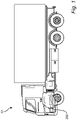
- Fig. 1 is lateral side view of a vehicle 10 according to an example embodiment.
- the vehicle 10 is in Fig. 1 illustrated in the form of a truck, but the noise shield arrangement described below in relation to Figs. 2 - 4 is applicable for other vehicles as well, such as a bus, a working machine, a car, etc.
- the vehicle 10 comprises a plurality of sound generating structures 200.
- the sound generating structure 200 is illustrated by the internal combustion engine of the vehicle.
- Other sound generating structures may, for example, be a compressor, a pump, an electric motor, etc.
- the noise shield arrangement 100 comprises a noise shield structure 102 which at least partially encapsulates the sound generating structure 200.
- the noise shield structure 102 comprises a first noise shield portion 120 formed by an acoustic isolating material.
- the noise shield structure 102 comprises a second noise shield portion 130 formed by a different acoustic isolating material compared to the first noise shield portion 120, whereby the first 120 and second 130 noise shield portions are connected to each other to properly prevent noise from being directed out to the environment.
- the present disclosure is applicable by using only the first noise shield portion 120, i.e. the first 120 and second 130 noise shield portions may be formed by the same material.
- the noise 300 generated by the sound generated structure 200 is schematically illustrated as prevented from being directed out from the noise shield structure 102.
- the noise shield structure 102 comprises a first surface 104 facing the sound generating structure 200, and a second surface 106 arranged on an opposite side of the noise shield structure 102 compared to the first surface 104. Hence, the second surface 106 faces away from the sound generating structure 200.
- the noise shield arrangement 100 further comprises a plurality of thermally conductive elements 110, in the following exemplified and referred to as thermally conductive pipes 110.
- the thermally conductive pipes 110 extend through the noise shield structure 102 between the first 104 and second 106 surfaces.
- the thermally conductive pipes 110 protrude a non-zero distance 140 out from the second surface 106.
- heat generated by the heat generating structure 200 is absorbed by a hot interface side 116 of the thermally conductive pipes 110 and transferred through the thermally conductive pipes 110 to a cold interface side 118.
- the hot interface side 116 is thus formed at a first end portion of the thermally conductive pipes 110 positioned on the same side as the first surface of the noise shield structure 102, and the cold interface side 118 is formed at a second end portion of the thermally conductive pipes 110 positioned at the non-zero distance 140 from the second surface 106.
- heat is directed from the encapsulated volume containing the sound generating structure 200 and directed through the noise shield structure 102 by means of the thermally conductive pipes 110 to a position arranged at a distance from the second surface 106.
- the thermally conductive pipes 110 comprises an angled portion 112 at the non-zero distance 140 from the second surface.
- the heat 350 transferred through the thermally conductive pipes 110 can be directed to a suitable position outside the encapsulated volume and routed to bypass other components of the vehicle.
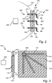
- FIG. 3 illustrating another example embodiment of the noise shield arrangement 100.
- a cross-section of the noise shield structure 102 is depicted, as well as a view towards the second surface 106.
- the noise shield arrangement 100 also comprises a plurality of thermally conductive pipes 110.
- the plurality of thermally conductive pipes 110 are united in a single passage 300 through the noise shield structure 102.
- three thermally conductive pipes 110 are arranged at the first surface 104 facing the sound generating structure 200. These three thermally conductive pipes 110 merge into a single thermally conductive pipe extending from the first surface 104 to the second surface 106 of the noise shield structure 102.
- the single thermally conductive pipe is split into three thermally conductive pipes 110 which protrudes the non-zero distance 140 out from the second surface 106.
- the thermally conductive pipes 110 extending out from the second surface 106 can be arranged in different directions to guide heat to various positions. Also, by providing a single passage through the noise shield structure 102, the noise shield structure can be preserved in its original configuration. Also, a single passage 300 may improve the ability to block noise from being directed through the noise shield structure 102.
- the thermally conductive pipes 110 are preferably heat pipes.
- Fig. 4 illustrates a heat pipe according to an example embodiment.
- the heat pipe 110 comprises a sealed inner cavity 402 and a casing 406 enclosing the inner cavity 402.
- an encapsulated volume 404 is formed between the inner cavity 402 and the casing 406.
- the encapsulated volume 404 comprises a liquid fluid 408.
- the heat pipe comprises the above described hot interface side 116 facing the sound generating structure 200, and the cold interface side 118. When the sound generating structure generates heat during operation, the heat is absorbed by the hot interface side and turned into vapor 355.
- the vapor 355 travels along the heat pipe 110 to the cold interface side 118 where it condenses back into a liquid 450 and the heat 350 is released at a suitable position outside the noise shield at the cold side interface 118.
- the liquid 450 thereafter returns to the hot interface side 116 through either capillary action or centrifugal force, and the cycle repeats, i.e. the liquid 355 once again turns into vapor.
Landscapes
- Physics & Mathematics (AREA)
- Acoustics & Sound (AREA)
- Engineering & Computer Science (AREA)
- Mechanical Engineering (AREA)
- Air-Conditioning For Vehicles (AREA)
Priority Applications (3)
| Application Number | Priority Date | Filing Date | Title |
|---|---|---|---|
| EP21158129.3A EP4046875A1 (de) | 2021-02-19 | 2021-02-19 | Lärmabschirmungsanordnung mit einem wärmeleitenden element |
| US17/666,764 US20220266772A1 (en) | 2021-02-19 | 2022-02-08 | Noise shield arrangement comprising a thermally conductive element |
| CN202210137796.XA CN114954279A (zh) | 2021-02-19 | 2022-02-15 | 用于车辆的噪声屏蔽装置和车辆 |
Applications Claiming Priority (1)
| Application Number | Priority Date | Filing Date | Title |
|---|---|---|---|
| EP21158129.3A EP4046875A1 (de) | 2021-02-19 | 2021-02-19 | Lärmabschirmungsanordnung mit einem wärmeleitenden element |
Publications (1)
| Publication Number | Publication Date |
|---|---|
| EP4046875A1 true EP4046875A1 (de) | 2022-08-24 |
Family
ID=74672147
Family Applications (1)
| Application Number | Title | Priority Date | Filing Date |
|---|---|---|---|
| EP21158129.3A Withdrawn EP4046875A1 (de) | 2021-02-19 | 2021-02-19 | Lärmabschirmungsanordnung mit einem wärmeleitenden element |
Country Status (3)
| Country | Link |
|---|---|
| US (1) | US20220266772A1 (de) |
| EP (1) | EP4046875A1 (de) |
| CN (1) | CN114954279A (de) |
Citations (6)
| Publication number | Priority date | Publication date | Assignee | Title |
|---|---|---|---|---|
| DE19735388A1 (de) * | 1997-08-14 | 1999-02-18 | Reinz Dichtungs Gmbh | Abschirmelement für Kraftfahrzeuge und Verfahren zur Abschirmung von Wärmestrahlern im Kfz |
| WO2007134391A1 (en) * | 2006-05-23 | 2007-11-29 | Bellmax Acoustic Pty Ltd | An acoustic shield |
| DE102006058989A1 (de) * | 2006-12-14 | 2008-06-19 | Elringklinger Ag | Abschirmbauteil, insbesondere Hitzeschild |
| US20180244216A1 (en) * | 2016-03-29 | 2018-08-30 | Mazda Motor Corporation | Attachment structure for heat insulating cover |
| CN111959613A (zh) * | 2020-09-15 | 2020-11-20 | 浙江玖和汽车车身股份有限公司 | 一种汽车发动机盖 |
| CN112046265A (zh) * | 2020-09-08 | 2020-12-08 | 张家港润盛科技材料有限公司 | 一种用于新能源汽车发动机支撑及散热的加强板结构及其加工方法 |
Family Cites Families (5)
| Publication number | Priority date | Publication date | Assignee | Title |
|---|---|---|---|---|
| CN100480612C (zh) * | 2006-04-28 | 2009-04-22 | 富准精密工业(深圳)有限公司 | 热管 |
| CN201276074Y (zh) * | 2008-07-30 | 2009-07-22 | 上汽通用五菱汽车股份有限公司 | 整体式汽车发动机吸音降噪的装置 |
| CN101824832A (zh) * | 2009-03-02 | 2010-09-08 | 沃尔沃建造设备控股(瑞典)有限公司 | 用于施工设备的具有噪声抑制器的发动机室 |
| JP5977117B2 (ja) * | 2012-08-28 | 2016-08-24 | 住友理工株式会社 | 車両用防音カバー |
| DE112017006319T5 (de) * | 2016-12-15 | 2019-09-19 | Leco Corporation | Chromatographiesystem |
-
2021
- 2021-02-19 EP EP21158129.3A patent/EP4046875A1/de not_active Withdrawn
-
2022
- 2022-02-08 US US17/666,764 patent/US20220266772A1/en not_active Abandoned
- 2022-02-15 CN CN202210137796.XA patent/CN114954279A/zh active Pending
Patent Citations (6)
| Publication number | Priority date | Publication date | Assignee | Title |
|---|---|---|---|---|
| DE19735388A1 (de) * | 1997-08-14 | 1999-02-18 | Reinz Dichtungs Gmbh | Abschirmelement für Kraftfahrzeuge und Verfahren zur Abschirmung von Wärmestrahlern im Kfz |
| WO2007134391A1 (en) * | 2006-05-23 | 2007-11-29 | Bellmax Acoustic Pty Ltd | An acoustic shield |
| DE102006058989A1 (de) * | 2006-12-14 | 2008-06-19 | Elringklinger Ag | Abschirmbauteil, insbesondere Hitzeschild |
| US20180244216A1 (en) * | 2016-03-29 | 2018-08-30 | Mazda Motor Corporation | Attachment structure for heat insulating cover |
| CN112046265A (zh) * | 2020-09-08 | 2020-12-08 | 张家港润盛科技材料有限公司 | 一种用于新能源汽车发动机支撑及散热的加强板结构及其加工方法 |
| CN111959613A (zh) * | 2020-09-15 | 2020-11-20 | 浙江玖和汽车车身股份有限公司 | 一种汽车发动机盖 |
Also Published As
| Publication number | Publication date |
|---|---|
| CN114954279A (zh) | 2022-08-30 |
| US20220266772A1 (en) | 2022-08-25 |
Similar Documents
| Publication | Publication Date | Title |
|---|---|---|
| Lajunen et al. | Recent developments in thermal management of electrified powertrains | |
| JP5484071B2 (ja) | 熱電発電機を搭載した車両 | |
| US20140034102A1 (en) | High efficiency thermoelectric generation | |
| JP4877389B2 (ja) | 自動変速機用コントロールユニット冷却装置 | |
| JP2007002839A (ja) | ガスタービンエンジンを動作させる方法及び装置 | |
| US20120055527A1 (en) | Structural element for thermally shielding engines or engine components, in particular a heat shield for combustion engines | |
| US9671172B2 (en) | Motor with cooled rotor | |
| US10197187B2 (en) | Fluid control valve | |
| KR20010041932A (ko) | 컴퓨터의 냉각 시스템 | |
| JP5538035B2 (ja) | ギア一体型電動モータ | |
| KR102882038B1 (ko) | 전기자동차용 배터리 승온 히터 | |
| US20220266772A1 (en) | Noise shield arrangement comprising a thermally conductive element | |
| CN103262392B (zh) | 具有改进的热管理的电机 | |
| JP2024033848A (ja) | マニホールド及びマニホールドの製造方法 | |
| US7877990B2 (en) | Metering device and internal combustion engine having a metering device | |
| JP6049726B2 (ja) | 熱パイプを介した電気モータの冷却 | |
| US7104080B2 (en) | Phase-change cooling system | |
| US20160339759A1 (en) | Cooling Loops Including Selective Direction Of Working Fluid and Vehicles Incorporating The Same | |
| JP7224724B2 (ja) | リザーブタンクの取付構造 | |
| JP2007315270A (ja) | インバータ一体型電動圧縮機 | |
| EP3445142B1 (de) | Elektronische ausstattung eines schienenfahrzeugs | |
| KR101745061B1 (ko) | 열전 발전 흡기 시스템 | |
| JPH08319812A (ja) | 防音形エンジン | |
| KR102901445B1 (ko) | 전동 압축기 | |
| JP2025071062A (ja) | 電気航空機を冷却するシステム及び方法 |
Legal Events
| Date | Code | Title | Description |
|---|---|---|---|
| PUAI | Public reference made under article 153(3) epc to a published international application that has entered the european phase |
Free format text: ORIGINAL CODE: 0009012 |
|
| STAA | Information on the status of an ep patent application or granted ep patent |
Free format text: STATUS: THE APPLICATION HAS BEEN PUBLISHED |
|
| AK | Designated contracting states |
Kind code of ref document: A1 Designated state(s): AL AT BE BG CH CY CZ DE DK EE ES FI FR GB GR HR HU IE IS IT LI LT LU LV MC MK MT NL NO PL PT RO RS SE SI SK SM TR |
|
| STAA | Information on the status of an ep patent application or granted ep patent |
Free format text: STATUS: REQUEST FOR EXAMINATION WAS MADE |
|
| 17P | Request for examination filed |
Effective date: 20230118 |
|
| RBV | Designated contracting states (corrected) |
Designated state(s): AL AT BE BG CH CY CZ DE DK EE ES FI FR GB GR HR HU IE IS IT LI LT LU LV MC MK MT NL NO PL PT RO RS SE SI SK SM TR |
|
| STAA | Information on the status of an ep patent application or granted ep patent |
Free format text: STATUS: EXAMINATION IS IN PROGRESS |
|
| 17Q | First examination report despatched |
Effective date: 20230704 |
|
| STAA | Information on the status of an ep patent application or granted ep patent |
Free format text: STATUS: THE APPLICATION IS DEEMED TO BE WITHDRAWN |
|
| 18D | Application deemed to be withdrawn |
Effective date: 20231115 |