EP4046869B1 - Hintergrundbeleuchtungsanordnung für komponenten mit unterschiedlichen optischen eigenschaften - Google Patents
Hintergrundbeleuchtungsanordnung für komponenten mit unterschiedlichen optischen eigenschaften Download PDFInfo
- Publication number
- EP4046869B1 EP4046869B1 EP21157803.4A EP21157803A EP4046869B1 EP 4046869 B1 EP4046869 B1 EP 4046869B1 EP 21157803 A EP21157803 A EP 21157803A EP 4046869 B1 EP4046869 B1 EP 4046869B1
- Authority
- EP
- European Patent Office
- Prior art keywords
- light
- film
- optical characteristic
- characteristic curve
- emitting device
- Prior art date
- Legal status (The legal status is an assumption and is not a legal conclusion. Google has not performed a legal analysis and makes no representation as to the accuracy of the status listed.)
- Active
Links
Images


Classifications
-
- F—MECHANICAL ENGINEERING; LIGHTING; HEATING; WEAPONS; BLASTING
- F21—LIGHTING
- F21S—NON-PORTABLE LIGHTING DEVICES; SYSTEMS THEREOF; VEHICLE LIGHTING DEVICES SPECIALLY ADAPTED FOR VEHICLE EXTERIORS
- F21S43/00—Signalling devices specially adapted for vehicle exteriors, e.g. brake lamps, direction indicator lights or reversing lights
- F21S43/20—Signalling devices specially adapted for vehicle exteriors, e.g. brake lamps, direction indicator lights or reversing lights characterised by refractors, transparent cover plates, light guides or filters
- F21S43/255—Filters
-
- B—PERFORMING OPERATIONS; TRANSPORTING
- B60—VEHICLES IN GENERAL
- B60Q—ARRANGEMENT OF SIGNALLING OR LIGHTING DEVICES, THE MOUNTING OR SUPPORTING THEREOF OR CIRCUITS THEREFOR, FOR VEHICLES IN GENERAL
- B60Q1/00—Arrangement of optical signalling or lighting devices, the mounting or supporting thereof or circuits therefor
- B60Q1/26—Arrangement of optical signalling or lighting devices, the mounting or supporting thereof or circuits therefor the devices being primarily intended to indicate the vehicle, or parts thereof, or to give signals, to other traffic
- B60Q1/2661—Arrangement of optical signalling or lighting devices, the mounting or supporting thereof or circuits therefor the devices being primarily intended to indicate the vehicle, or parts thereof, or to give signals, to other traffic mounted on parts having other functions
-
- B—PERFORMING OPERATIONS; TRANSPORTING
- B60—VEHICLES IN GENERAL
- B60Q—ARRANGEMENT OF SIGNALLING OR LIGHTING DEVICES, THE MOUNTING OR SUPPORTING THEREOF OR CIRCUITS THEREFOR, FOR VEHICLES IN GENERAL
- B60Q3/00—Arrangement of lighting devices for vehicle interiors; Lighting devices specially adapted for vehicle interiors
- B60Q3/50—Mounting arrangements
- B60Q3/54—Lighting devices embedded in interior trim, e.g. in roof liners
-
- B—PERFORMING OPERATIONS; TRANSPORTING
- B60—VEHICLES IN GENERAL
- B60Q—ARRANGEMENT OF SIGNALLING OR LIGHTING DEVICES, THE MOUNTING OR SUPPORTING THEREOF OR CIRCUITS THEREFOR, FOR VEHICLES IN GENERAL
- B60Q3/00—Arrangement of lighting devices for vehicle interiors; Lighting devices specially adapted for vehicle interiors
- B60Q3/60—Arrangement of lighting devices for vehicle interiors; Lighting devices specially adapted for vehicle interiors characterised by optical aspects
- B60Q3/62—Arrangement of lighting devices for vehicle interiors; Lighting devices specially adapted for vehicle interiors characterised by optical aspects using light guides
- B60Q3/64—Arrangement of lighting devices for vehicle interiors; Lighting devices specially adapted for vehicle interiors characterised by optical aspects using light guides for a single lighting device
-
- F—MECHANICAL ENGINEERING; LIGHTING; HEATING; WEAPONS; BLASTING
- F21—LIGHTING
- F21S—NON-PORTABLE LIGHTING DEVICES; SYSTEMS THEREOF; VEHICLE LIGHTING DEVICES SPECIALLY ADAPTED FOR VEHICLE EXTERIORS
- F21S43/00—Signalling devices specially adapted for vehicle exteriors, e.g. brake lamps, direction indicator lights or reversing lights
- F21S43/20—Signalling devices specially adapted for vehicle exteriors, e.g. brake lamps, direction indicator lights or reversing lights characterised by refractors, transparent cover plates, light guides or filters
- F21S43/26—Refractors, transparent cover plates, light guides or filters not provided in groups F21S43/235 - F21S43/255
-
- F—MECHANICAL ENGINEERING; LIGHTING; HEATING; WEAPONS; BLASTING
- F21—LIGHTING
- F21S—NON-PORTABLE LIGHTING DEVICES; SYSTEMS THEREOF; VEHICLE LIGHTING DEVICES SPECIALLY ADAPTED FOR VEHICLE EXTERIORS
- F21S43/00—Signalling devices specially adapted for vehicle exteriors, e.g. brake lamps, direction indicator lights or reversing lights
- F21S43/50—Signalling devices specially adapted for vehicle exteriors, e.g. brake lamps, direction indicator lights or reversing lights characterised by aesthetic components not otherwise provided for, e.g. decorative trim, partition walls or covers
-
- F—MECHANICAL ENGINEERING; LIGHTING; HEATING; WEAPONS; BLASTING
- F21—LIGHTING
- F21S—NON-PORTABLE LIGHTING DEVICES; SYSTEMS THEREOF; VEHICLE LIGHTING DEVICES SPECIALLY ADAPTED FOR VEHICLE EXTERIORS
- F21S43/00—Signalling devices specially adapted for vehicle exteriors, e.g. brake lamps, direction indicator lights or reversing lights
- F21S43/10—Signalling devices specially adapted for vehicle exteriors, e.g. brake lamps, direction indicator lights or reversing lights characterised by the light source
- F21S43/13—Signalling devices specially adapted for vehicle exteriors, e.g. brake lamps, direction indicator lights or reversing lights characterised by the light source characterised by the type of light source
- F21S43/14—Light emitting diodes [LED]
-
- F—MECHANICAL ENGINEERING; LIGHTING; HEATING; WEAPONS; BLASTING
- F21—LIGHTING
- F21S—NON-PORTABLE LIGHTING DEVICES; SYSTEMS THEREOF; VEHICLE LIGHTING DEVICES SPECIALLY ADAPTED FOR VEHICLE EXTERIORS
- F21S43/00—Signalling devices specially adapted for vehicle exteriors, e.g. brake lamps, direction indicator lights or reversing lights
- F21S43/20—Signalling devices specially adapted for vehicle exteriors, e.g. brake lamps, direction indicator lights or reversing lights characterised by refractors, transparent cover plates, light guides or filters
- F21S43/235—Light guides
-
- F—MECHANICAL ENGINEERING; LIGHTING; HEATING; WEAPONS; BLASTING
- F21—LIGHTING
- F21W—INDEXING SCHEME ASSOCIATED WITH SUBCLASSES F21K, F21L, F21S and F21V, RELATING TO USES OR APPLICATIONS OF LIGHTING DEVICES OR SYSTEMS
- F21W2104/00—Exterior vehicle lighting devices for decorative purposes
Definitions
- the present invention is directed to a backlight assembly with components having different optical characteristics. Moreover, the present invention relates to a vehicle comprising such a backlight assembly.
- Backlight components are playing an increasingly important role in the interior and exterior design of a vehicle.
- Non-exhaustive examples of external cladding components which could be backlit are front grilles, side skirts, bumpers, tailgates and spoilers.
- Non-exhaustive examples of internal backlit components are instrument panels, door panels, center consoles and internal trims.
- the backlit components are made by injection molding, however, within the present invention the components are not limited to injection molded parts and can for example be made of metal, glass or the like having optical light transmission characteristics.
- US 2015/0210226 A1 discloses a vehicle trim element has a panel that includes at least one colored mask having solid areas and at least one aperture delimiting a pattern, and a colored screen transmitting light and closing each aperture of the mask. Further documents disclosing the relevant prior art are EP 1 839 945 A1 , US 6 31 8 872 B1 and US 2004/239750 A1 .It is one task of the present invention to present a vehicle backlighting assembly with at least two components having different optical characteristics to produce a homogeneous light appearance when the light emitting device is turned on and a homogeneous surface appearance when the light emitting device is turned off.
- a backlighting assembly for a vehicle comprises
- the film provides a light spectrum modification to the light impinging on the first member by altering the beam of light from the light source before the light impinges the first member. This modification allows a common light source to be used for both members where the output transmitted light through the first and second members has a homogenized appearance.
- the light spectrum modification may be an optical characteristic to absorb and/or reflect a selected light spectrum.
- the appearance of the backlight spectrum visible through the first member is to be homogenous with the backlight spectrum through the second member.
- the film provides a light spectrum modification to the light impinging on the first member to correct the output backlight spectrum visible through the first member.
- the film reduces and/or eliminates a determined light spectrum from reaching the surface of the first member.
- the film is chosen with an optical characteristic to absorb and/or reflect a determined light spectrum to prevent this determined light spectrum from impinging the inner surface of the first member.
- the light spectrum modification is determined from a transmittance variance between the first optical characteristic of the first member and the second optical characteristic of the second member.
- Determining the transmittance variance between the emitted backlight spectrum though the first member compared to the backlight spectrum of the second member indicates where the optical characteristics of the first member deviate from the optical characteristics of the second member.
- the film optical characteristics are then chosen to using the transmittance variance between the light spectrum of the first member and the second member.
- the film optical characteristics in combination with the optical characteristics of the first member will produce a backlight spectrum to be visually indistinguishable from the backlight spectrum of the second member.
- the optical characteristics needed to provide the light spectrum modification to the beam of light may be complex.
- a single film may not have all the optical characteristics to provide the entire desired light modification.
- a film with at least two film layers, each having different optical characteristics, may cooperate to provide the desired light spectrum modification.
- the first member and the second member are opaque with at least one light transmitting recess.
- Backlighting can be used to display information on the surface.
- information can be displayed in graphic form on the surface of the first and second members when the light source is energized.
- the at least one light transmitting recess is a circle, triangle, arrow, logo, emblem or words.
- the light transmitting recess can be shaped based to display backlit information in recognizable form. Circles, triangles, arrows, logos, emblems and words are all recognizable shapes which can convey information when illuminated.
- the light emitting device is at least one light emitting diode (LED) source.
- LED light emitting diode
- Light emitting diodes may be used in some applications. They provide a low heat light source and can be packaged with few constraints.
- the backlighting assembly further comprises a second film adhered to the second member, wherein the second film provides a second light spectrum modification of the beam of light from the light emitting device to create a second modified beam of light which impinges the second member.
- the difference between optical characteristics of the first member and the optical characteristics of the second member may complex or produce transmittance curves which overlap. Utilizing a film on the first member to provide a light modification in cooperation with a second film on the second member to provide a second light modification may provide a less complex solution for light spectrum modification than utilizing a film on the first member alone.
- first member and the second member may be interior or exterior components.
- Interior and exterior components may have a backlighting component which occurs through two components located side by side.
- the use of light spectrum modification to provide a homogenized output light spectrum may be applied to any multicomponent backlighting assembly.
- Figure 1a illustrates a side view of an existing backlighting assembly 10 according to the prior art.
- a light emitting device 12 emits a beam of light 14 which at least partially impinges on an inner surface 22 of a first member 16 and at least partially impinges on an inner surface 20 of a second member 18.
- the first member 16 is arranged side by side to the second member 18 in Figure 1 .
- the first and second members 16, 18 may be any part used in exterior cladding applications such as bumpers, side skirts, tailgates, A-pillars, B- pillars, spoilers and the like.
- the first and second members 16, 18 may also be interior components used in applications such as instrument panels, consoles, door trim panels and the like.
- the light emitting device 12 may be a light emitting diode (LED) source.
- the light emitting device 12 may also have multiple light sources (not shown).
- the light emitting device 12 may also contain a light guide with one or more LED's coupled to the light guide where the light guide could be of a material with light transmission properties such as PMMA, PC, or glass as non-limiting examples.
- the material optical characteristics of the first member 16 are dissimilar from the material optical characteristics across the light spectrum of the second member 18 ( Figure 2 ).
- Optical characteristics include transmissivity, reflectivity and absorptivity. Therefore when the beam of light 14 impinges on the inner surface 22 a portion of the beam of light 14 may be reflected and/or absorbed and/or transmitted through the material of the first member 16.
- the beam of light 14 is transmitted through the first member 16 according to its optical characteristics producing a first external beam of light 24 with a first light spectrum visible through the outer surface 28.
- the first member 16 may absorb a particular light spectrum as the beam of light 14 passes through the first member 16.
- a second external beam of light 26 with a second light spectrum visible through an outer surface 30 is created by the material optical characteristics of the second member 18.
- the output light spectrum contrast between the first and second external beams of light 24, 26 may be due to the absorption of a particular light spectrum in the material of the second member 18 which is not absorbed by the material of the first member 16 as the beam of light 14 is transmitted through the different optical characteristics of the first and second members 16, 18.
- the light spectrum of the first external beam of light 24 is viewed as a first light spectrum color 32 and the second external beam of light 26 is viewed as a second light spectrum color 33.
- Figure 1b illustrates the visible contrast between the first light spectrum color 32 visible through the outer surface 28 and the second light spectrum color 33 visible through the outer surface 30. This contrast is created by the different optical characteristics between the first member 16 material and the second member 18 material. The contrast in light spectrum colors creates a non-homogenized appearance in the backlighting assembly 10 viewing when the light emitting device 12 is energized. As illustrated in Figure 1b , the first light spectrum color 32 is visibly distinct from the second light spectrum color 33 which may detract from the overall design aesthetic and/or give the impression of poor quality.
- Figure 2 illustrates an exemplary graphical representation of a first optical characteristic curve 34 for the first member 16 and a second optical characteristic curve 35 for the second member 18 ( Figure 1a ).
- the first and second optical characteristic curves 34, 35 extends and may vary across the visible light spectrum.
- the first optical characteristic curve 34 has distinct optical characteristics over the visible light spectrum when compared to the second optical characteristic curve 35 creating an optical characteristic variance 37. It is the optical characteristic variance 37 which produces the non-homogenized appearance between the first light spectrum color 32 and the second light spectrum color 33.
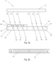
- Figure 3a illustrates a side view of a first embodiment of the backlighting assembly 11.
- a film 36 is adhered to the inner surface 22 of the first member 16.
- the light emitting device 12 emits a beam of light 14 which at least partially impinges on an inner surface 38 of the film 36 and at least partially impinges on the inner surface 20 of the second member 18.
- the film 36 is characterized by optical characteristics to provide light spectrum modification to the beam of light 14 creating a modified beam of light 40.
- the modified beam of light 40 then impinges on the inner surface 22 of the first member 16.
- the modified beam of light 40 transmits according to the first optical characteristics through the first member 16 to create a modified external beam of light 42.
- Figure 3b illustrates the modified external beam of light 42 visible through the outer surface 28 as a modified light spectrum color 44.
- the modified light spectrum color 44 is visually indistinguishable by an observer from the second light spectrum color 33 visible through the outer surface 30 creating a homogenized appearance.
- the second light spectrum color 33 from the second external beam of light 26 and modified light spectrum color 44 from the modified external beam of light 42 can be measured and compared using known color measuring techniques.
- the film 36 in combination with the first member 16 creates a stack which will produce the visually similar output light spectrum for the input beam of light 14 as compared to the output light spectrum of the second external beam of light 26 of the second member 18.
- the optical characteristics of the film 36 are determined by the first optical characteristics curve 34 as compared to the second optical characteristic curve 35.
- the optical characteristic variance 37 is the difference between the first optical characteristic curve 34 of the first member 16 and the second optical characteristic curve 35 of the second member 18 as shown in Figure 2 .
- the film 36 has film optical characteristics which when applied modify transmission of the first optical characteristic curve 34 to reach the second optical characteristic curve 35 and minimize the optical characteristic variance 37.
- the first optical characteristic curve 34 of the first member 16 transmits 870 of the light at 400 nm while the second optical characteristics curve 35 transmits 780 of the light at 400 nm ( Figure 2 ).
- the optical characteristic variance 37 is used along the visible light spectrum to determine the optical characteristics of the film 36 in the visible spectrum.
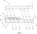
- Figure 4 is a side view through a second embodiment of a backlighting assembly 50.
- the film 36 has at least two layers with different optical characteristics to produce a modified beam of light 40.
- a first film layer 52 and a second film layer 53 with different material optical characteristics cooperate to provide the desired light spectrum modification to the beam of light 14.
- the beam of light 14 impinges on an inner surface 54 of the first film layer 52.
- a modified beam of light 56 is produced and impinges on the inner surface 55 of the second film layer 53.
- This modified beam of light 56 is further modified by the optical characteristics of the second film layer 53 to produce the modified beam of light 40 which impinges on the inner surface of the first member 16.
- the modified beam of light 40 passes through the first member 16 and is altered based on the material optical characteristics of the first member to produce a first external beam of light 42.
- the first external beam of light 42 produces a first color 44 as describe in reference to Figure 3 which is virtually indistinguishable from the second light spectrum color 33.
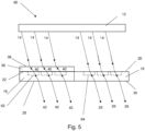
- FIG. 5 a side view of a third embodiment of a backlighting assembly 60 is illustrated.
- the first member 16 has at least one first member recess 62 and the second member 18 has at least one second member recess 64.
- the at least one first member recess 62 and the at least one second member recess 64 may be formed when the first member 16 and/or second member 18 are manufactured.
- the at least one first and/or second member recesses 62, 64 may be created after manufacturing of the first and/or second member 16, 18 by removing material such as with a laser etching process or the like.
- the film 36 is adhered to the inner surface 22 of the first member 16 and provides a light spectrum modification to the beam of light 14 to produce the modified beam of light 40 as described above in relation to Figure 2 , 3a and 3b .
- the first member 16 and the second member 18 are opaque.
- the at least one first member recess 62 and the at least one second member recess 64 provide a reduced thickness sections in the first and second members 16, 18 which are capable to transmit light and provide a backlight effect.
- the modified beam of light 40 is only transmittable through the at least one first member recess 62 and the beam of light 14 is only transmittable through the at least one second member recess 64.
- the at least one first member recess 62 and at least one second member recess 64 will provide a specific geometry or pattern of light to be visible through the outer surfaces 28, 30 when the light emitting device 12 is illuminated.
- the geometry or shape of the at least one first member recess 62 and the at least one second member recess 64 may be any configuration such as triangles, arrows, circles, logos, emblems or words as non-limiting examples.
- the optical characteristics of the film 36 is calculated as described in the example above for the first embodiment of the backlighting assembly 11.
- Figure 6 illustrates the third embodiment of the backlight assembly 60 when the light emitting device 12 (not shown) is not energized.
- Figure 7 illustrates the third embodiment of the backlight assembly 60 when the light emitting device 12 (not shown) is energized.
- the beam of light 14 is transmitted through the first and second members 16, 18 at the first and second member recesses 62, 64, the beam of light 14 produces the modified external beam of light 42 and the second external beam of light ( Figure 5 ).
- the at least one first member recess 62 and at least one second member recess 64 are shaped to produce a circular backlighting effect for each recess. This creates the homogenized pattern of light visible on the outer surfaces 28, 30.
- Figure 8 illustrates a fourth embodiment of the backlight assembly 70.
- the difference between optical characteristics of the first member and the optical characteristics of the second member may complex or produce transmittance curves which overlap as shown in Figure 9 .
- Utilizing a first member film 71 for light modification on first member 16 and a second member film 73 with different optical characteristics on the second member 18 may provide a less complex film solution for light spectrum modification than utilizing a film on a single member.
- the first member 16 has a first member film 71 applied to the inner surface 22 and the second member 18 has a second member film 73 applied to the inner surface 20.
- the beam of light 14 passes through the first member film 71 creating a modified beam of light 75 according to the optical characteristics of the first member film 71.
- This modified beam of light 75 impinges on the inner surface 22 of the first member and creates a first external beam of light 76.
- the beam of light 14 impinges of the second inner surface 74 of the second member film 73.
- the second member film 73 provides a second light spectrum modification different from the first member film 71 to the beam of light 14 producing a second modified beam of light 77.
- This second modified beam of light 77 impinges on the inner surface 20 of the second member 18.
- the modified beam of light 77 transmits through the second member 18 producing a second modified external beam of light 78.
- the first modified external beam of light 76 has a light spectrum color which produces a homogenized appearance with the light spectrum color from the second modified external beam of light 78.
- Figure 9 illustrates when the first member 16 optical characteristics and the second member 18 optical characteristics overlap at points in the visible light spectrum.
- the beam of light 14 will be altered by a first member film 71 before impinging on the first member 16 and by a second member film 73 before impinging on the second member 18.
- the use of the first member and second member films 71, 73 produces a homogenized color appearance between the first and second members 16, 18 for the backlighting assembly 70.
- the first member 16 has a third optical characteristic curve 79 and the second member 18 has fourth optical characteristic curve 80.
- the optical characteristics of the first member film 71 for the first member 16 is calculated based on the optical variance 82 which occurs when the third optical characteristic curve 79 has a higher transmittance percentage than the fourth optical characteristic curve 80 at a selected wavelength.
- the first member film 71 reduces the transmittance at a particular wavelength for the third optical characteristic curve to the transmittance rate of the fourth optical characteristic curve 80.
- the optical characteristics for the second member film 73 are calculated from the optical variance 84 which occurs when the fourth optical characteristic curve 80 has a higher transmittance percentage than the third optical characteristic curve 79 at a selected wavelength.
- the second member film 73 reduces the transmittance of the fourth optical characteristic curve 80 to the transmittance rate of the third optical characteristic curve 79.
- the first member film 71 in cooperation with the first member 16 and the second member film 73 in cooperation with the second member 18 create a combined optical characteristic curve 86 for the first and second members 16, 18. This combined optical characteristic curve 86 produces a homogenized external light appearance for the first and second members 16, 18 when the light emitting device 12 is energized.
Landscapes
- Engineering & Computer Science (AREA)
- General Engineering & Computer Science (AREA)
- Mechanical Engineering (AREA)
- Planar Illumination Modules (AREA)
Claims (8)
- Hintergrundbeleuchtungsanordnung (11) für ein Fahrzeug, die aufweist:- ein erstes Element (16), wobei das erste Element (16) eine erste optische Kennlinie (34) aufweist, die der prozentuale Transmissionsgrad in Abhängigkeit von der Wellenlänge ist;- ein zweites Element (18), das zu dem ersten Element (16) benachbart ist, wobei das zweite Element (18) eine zweite optische Kennlinie (35) aufweist, die der prozentuale Transmissionsgrad in Abhängigkeit von der Wellenlänge ist, wobei sich die zweite optische Kennlinie (35) von der ersten optischen Kennlinie (34) unterscheidet;- wobei das erste Element (16) und das zweite Element (18) nebeneinander angeordnet sind;- einen Film (36), der an dem ersten Element (16) haftet; und- eine lichtemittierende Einrichtung (12), die einen Lichtstrahl (14) emittiert, wobei die lichtemittierende Einrichtung (12) so positioniert ist, dass ein Lichtstrahl (14) teilweise auf das zweite Element (18) auftrifft und teilweise auf den Film (36) auftrifft;- wobei der Film (36) eine Lichtspektrumsmodifikation des Lichtstrahls (14) von der lichtemittierenden Einrichtung (12) über das Spektrum des sichtbaren Lichts ermöglicht, um einen modifizierten Lichtstrahl (40), der auf das erste Element (16) auftrifft, zu erzeugen; und- wobei die Lichtspektrummodifikation aus einer Transmissionsgradabweichung zwischen der ersten optischen Kennlinie (34) des ersten Elements (16) und der zweiten optischen Kennlinie (35) des zweiten Elements (18) bestimmt wird, so dass eine gemeinsame lichtemittierende Einrichtung (12) für beide Elemente (16, 18) verwendet werden kann, wobei das durch das erste und zweite Element (16, 18) gesendete Ausgangslicht für einen Beobachter ein homogenisiertes Erscheinungsbild aufweist.
- Hintergrundbeleuchtungsanordnung (11) nach Anspruch 1, wobei die Lichtspektrummodifikation eine optische Eigenschaft, um ein ausgewähltes Lichtspektrum zu absorbieren und/oder reflektieren, ist.
- Hintergrundbeleuchtungsanordnung (11) nach Anspruch 1, wobei der Film(36) zumindest zwei Filmschichten (52, 53) aufweist, um die Lichtspektrummodifikation bereitzustellen.
- Hintergrundbeleuchtungsanordnung (11) nach Anspruch 1, wobei das erste Element (16) und das zweite Element (18) undurchsichtig mit zumindest einer lichtdurchlässigen Aussparung (62, 64) sind.
- Hintergrundbeleuchtungsanordnung (11) nach Anspruch 4, wobei die zumindest eine lichtdurchlässige Aussparung (62, 64) ein Kreis, ein Dreieck, ein Pfeil, ein Logo, ein Emblem ist oder Wörter sind.
- Hintergrundbeleuchtungsanordnung (11) nach Anspruch 1, wobei die lichtemittierende Einrichtung (12) zumindest eine Leuchtdioden (LED)-Quelle ist.
- Hintergrundbeleuchtungsanordnung (11) nach Anspruch 1, die weiterhin einen zweiten Film (71), der an dem zweiten Element (18) haftet, aufweist, wobei der zweite Film (71) eine zweite Lichtspektrummodifikation des Lichtstrahls (14) von der lichtemittierenden Einrichtung (12) bereitstellt, um einen zweiten modifizierten Lichtstrahl (74), der auf das zweite Element (18) auftrifft, zu erzeugen.
- Hintergrundbeleuchtungsanordnung (11) nach Anspruch 1, wobei das erste Element (16) und das zweite Element (18) innere oder äußere Komponenten sind.
Priority Applications (2)
| Application Number | Priority Date | Filing Date | Title |
|---|---|---|---|
| ES21157803T ES2977815T3 (es) | 2021-02-18 | 2021-02-18 | Conjunto de retroiluminación para componentes de características ópticas variables |
| EP21157803.4A EP4046869B1 (de) | 2021-02-18 | 2021-02-18 | Hintergrundbeleuchtungsanordnung für komponenten mit unterschiedlichen optischen eigenschaften |
Applications Claiming Priority (1)
| Application Number | Priority Date | Filing Date | Title |
|---|---|---|---|
| EP21157803.4A EP4046869B1 (de) | 2021-02-18 | 2021-02-18 | Hintergrundbeleuchtungsanordnung für komponenten mit unterschiedlichen optischen eigenschaften |
Publications (2)
| Publication Number | Publication Date |
|---|---|
| EP4046869A1 EP4046869A1 (de) | 2022-08-24 |
| EP4046869B1 true EP4046869B1 (de) | 2024-02-14 |
Family
ID=74668660
Family Applications (1)
| Application Number | Title | Priority Date | Filing Date |
|---|---|---|---|
| EP21157803.4A Active EP4046869B1 (de) | 2021-02-18 | 2021-02-18 | Hintergrundbeleuchtungsanordnung für komponenten mit unterschiedlichen optischen eigenschaften |
Country Status (2)
| Country | Link |
|---|---|
| EP (1) | EP4046869B1 (de) |
| ES (1) | ES2977815T3 (de) |
Family Cites Families (5)
| Publication number | Priority date | Publication date | Assignee | Title |
|---|---|---|---|---|
| JP4186362B2 (ja) * | 1999-05-25 | 2008-11-26 | 株式会社デンソー | 計器 |
| DE10141751A1 (de) * | 2001-08-29 | 2003-03-27 | Siemens Ag | Verfahren zur Herstellung eines Zifferblattes und danach hergestelltes Zifferblatt |
| JP4993985B2 (ja) * | 2006-03-30 | 2012-08-08 | カルソニックカンセイ株式会社 | 可変表示構造 |
| FR3016839B1 (fr) * | 2014-01-27 | 2017-06-09 | Faurecia Interieur Ind | Element d'habillage de vehicule |
| JP6786302B2 (ja) * | 2016-08-12 | 2020-11-18 | 株式会社小糸製作所 | 照明装置 |
-
2021
- 2021-02-18 ES ES21157803T patent/ES2977815T3/es active Active
- 2021-02-18 EP EP21157803.4A patent/EP4046869B1/de active Active
Also Published As
| Publication number | Publication date |
|---|---|
| EP4046869A1 (de) | 2022-08-24 |
| ES2977815T3 (es) | 2024-08-30 |
Similar Documents
| Publication | Publication Date | Title |
|---|---|---|
| US11745671B2 (en) | Backlit vehicle interior panel with specialty materials | |
| US7216997B2 (en) | Phosphor reactive instrument panel and gauges | |
| JP6427006B2 (ja) | 積層基板上の画像を見るための装置 | |
| US8591051B2 (en) | Panel and method for producing the same | |
| US10513222B2 (en) | Motor vehicle trim part with illumination | |
| US10269330B2 (en) | Vehicle interior equipment with a screen, corresponding management process | |
| CN102901020B (zh) | 激光成形挡板 | |
| JP2015513684A5 (de) | ||
| US10789865B2 (en) | Display element with transition lamination of partial films and coatings | |
| EP3802218A1 (de) | Hinterleuchtbares zierelement für ein fahrzeug | |
| US20200039431A1 (en) | Molded part and method for manufacturing such a molded part | |
| CN220038269U (zh) | 一种车辆饰件 | |
| EP3908481B1 (de) | Abdeckvorrichtung, karosserieteil und kraftfahrzeug | |
| US12568719B2 (en) | Display device and method of manufacturing display device | |
| US9643532B2 (en) | Method for producing a light for vehicles and exterior mirror assembly of a vehicle with a lamp thus prepared | |
| EP3376098B1 (de) | Anzeigevorrichtung | |
| US7278748B2 (en) | Display apparatus | |
| EP3184363B1 (de) | Beleuchtungsvorrichtung für eine innenverkleidung eines fahrzeugs | |
| US20200355340A1 (en) | Warning light for blind area of lane change | |
| JP5820286B2 (ja) | 自動車用照明プレート | |
| CN115503473A (zh) | 选择性显示至少一个代表开关功能和/或多个开关状态的符号的功能显示器和相关操作元件 | |
| EP4046869B1 (de) | Hintergrundbeleuchtungsanordnung für komponenten mit unterschiedlichen optischen eigenschaften | |
| US8101265B2 (en) | Combination instrument | |
| JP2002156925A (ja) | 表示板 | |
| JP2008185753A (ja) | 表示装置 |
Legal Events
| Date | Code | Title | Description |
|---|---|---|---|
| PUAI | Public reference made under article 153(3) epc to a published international application that has entered the european phase |
Free format text: ORIGINAL CODE: 0009012 |
|
| STAA | Information on the status of an ep patent application or granted ep patent |
Free format text: STATUS: THE APPLICATION HAS BEEN PUBLISHED |
|
| AK | Designated contracting states |
Kind code of ref document: A1 Designated state(s): AL AT BE BG CH CY CZ DE DK EE ES FI FR GB GR HR HU IE IS IT LI LT LU LV MC MK MT NL NO PL PT RO RS SE SI SK SM TR |
|
| STAA | Information on the status of an ep patent application or granted ep patent |
Free format text: STATUS: REQUEST FOR EXAMINATION WAS MADE |
|
| 17P | Request for examination filed |
Effective date: 20230216 |
|
| RBV | Designated contracting states (corrected) |
Designated state(s): AL AT BE BG CH CY CZ DE DK EE ES FI FR GB GR HR HU IE IS IT LI LT LU LV MC MK MT NL NO PL PT RO RS SE SI SK SM TR |
|
| P01 | Opt-out of the competence of the unified patent court (upc) registered |
Effective date: 20230427 |
|
| GRAP | Despatch of communication of intention to grant a patent |
Free format text: ORIGINAL CODE: EPIDOSNIGR1 |
|
| STAA | Information on the status of an ep patent application or granted ep patent |
Free format text: STATUS: GRANT OF PATENT IS INTENDED |
|
| INTG | Intention to grant announced |
Effective date: 20231030 |
|
| GRAS | Grant fee paid |
Free format text: ORIGINAL CODE: EPIDOSNIGR3 |
|
| GRAA | (expected) grant |
Free format text: ORIGINAL CODE: 0009210 |
|
| STAA | Information on the status of an ep patent application or granted ep patent |
Free format text: STATUS: THE PATENT HAS BEEN GRANTED |
|
| AK | Designated contracting states |
Kind code of ref document: B1 Designated state(s): AL AT BE BG CH CY CZ DE DK EE ES FI FR GB GR HR HU IE IS IT LI LT LU LV MC MK MT NL NO PL PT RO RS SE SI SK SM TR |
|
| REG | Reference to a national code |
Ref country code: GB Ref legal event code: FG4D |
|
| REG | Reference to a national code |
Ref country code: CH Ref legal event code: EP |
|
| REG | Reference to a national code |
Ref country code: DE Ref legal event code: R096 Ref document number: 602021009270 Country of ref document: DE |
|
| REG | Reference to a national code |
Ref country code: IE Ref legal event code: FG4D |
|
| REG | Reference to a national code |
Ref country code: LT Ref legal event code: MG9D |
|
| REG | Reference to a national code |
Ref country code: NL Ref legal event code: MP Effective date: 20240214 |
|
| PG25 | Lapsed in a contracting state [announced via postgrant information from national office to epo] |
Ref country code: IS Free format text: LAPSE BECAUSE OF FAILURE TO SUBMIT A TRANSLATION OF THE DESCRIPTION OR TO PAY THE FEE WITHIN THE PRESCRIBED TIME-LIMIT Effective date: 20240614 |
|
| PG25 | Lapsed in a contracting state [announced via postgrant information from national office to epo] |
Ref country code: LT Free format text: LAPSE BECAUSE OF FAILURE TO SUBMIT A TRANSLATION OF THE DESCRIPTION OR TO PAY THE FEE WITHIN THE PRESCRIBED TIME-LIMIT Effective date: 20240214 |
|
| PG25 | Lapsed in a contracting state [announced via postgrant information from national office to epo] |
Ref country code: GR Free format text: LAPSE BECAUSE OF FAILURE TO SUBMIT A TRANSLATION OF THE DESCRIPTION OR TO PAY THE FEE WITHIN THE PRESCRIBED TIME-LIMIT Effective date: 20240515 |
|
| REG | Reference to a national code |
Ref country code: AT Ref legal event code: MK05 Ref document number: 1656785 Country of ref document: AT Kind code of ref document: T Effective date: 20240214 |
|
| PG25 | Lapsed in a contracting state [announced via postgrant information from national office to epo] |
Ref country code: HR Free format text: LAPSE BECAUSE OF FAILURE TO SUBMIT A TRANSLATION OF THE DESCRIPTION OR TO PAY THE FEE WITHIN THE PRESCRIBED TIME-LIMIT Effective date: 20240214 Ref country code: NL Free format text: LAPSE BECAUSE OF FAILURE TO SUBMIT A TRANSLATION OF THE DESCRIPTION OR TO PAY THE FEE WITHIN THE PRESCRIBED TIME-LIMIT Effective date: 20240214 Ref country code: RS Free format text: LAPSE BECAUSE OF FAILURE TO SUBMIT A TRANSLATION OF THE DESCRIPTION OR TO PAY THE FEE WITHIN THE PRESCRIBED TIME-LIMIT Effective date: 20240514 |
|
| PG25 | Lapsed in a contracting state [announced via postgrant information from national office to epo] |
Ref country code: AT Free format text: LAPSE BECAUSE OF FAILURE TO SUBMIT A TRANSLATION OF THE DESCRIPTION OR TO PAY THE FEE WITHIN THE PRESCRIBED TIME-LIMIT Effective date: 20240214 |
|
| PG25 | Lapsed in a contracting state [announced via postgrant information from national office to epo] |
Ref country code: RS Free format text: LAPSE BECAUSE OF FAILURE TO SUBMIT A TRANSLATION OF THE DESCRIPTION OR TO PAY THE FEE WITHIN THE PRESCRIBED TIME-LIMIT Effective date: 20240514 Ref country code: NO Free format text: LAPSE BECAUSE OF FAILURE TO SUBMIT A TRANSLATION OF THE DESCRIPTION OR TO PAY THE FEE WITHIN THE PRESCRIBED TIME-LIMIT Effective date: 20240514 Ref country code: NL Free format text: LAPSE BECAUSE OF FAILURE TO SUBMIT A TRANSLATION OF THE DESCRIPTION OR TO PAY THE FEE WITHIN THE PRESCRIBED TIME-LIMIT Effective date: 20240214 Ref country code: LT Free format text: LAPSE BECAUSE OF FAILURE TO SUBMIT A TRANSLATION OF THE DESCRIPTION OR TO PAY THE FEE WITHIN THE PRESCRIBED TIME-LIMIT Effective date: 20240214 Ref country code: IS Free format text: LAPSE BECAUSE OF FAILURE TO SUBMIT A TRANSLATION OF THE DESCRIPTION OR TO PAY THE FEE WITHIN THE PRESCRIBED TIME-LIMIT Effective date: 20240614 Ref country code: HR Free format text: LAPSE BECAUSE OF FAILURE TO SUBMIT A TRANSLATION OF THE DESCRIPTION OR TO PAY THE FEE WITHIN THE PRESCRIBED TIME-LIMIT Effective date: 20240214 Ref country code: GR Free format text: LAPSE BECAUSE OF FAILURE TO SUBMIT A TRANSLATION OF THE DESCRIPTION OR TO PAY THE FEE WITHIN THE PRESCRIBED TIME-LIMIT Effective date: 20240515 Ref country code: FI Free format text: LAPSE BECAUSE OF FAILURE TO SUBMIT A TRANSLATION OF THE DESCRIPTION OR TO PAY THE FEE WITHIN THE PRESCRIBED TIME-LIMIT Effective date: 20240214 Ref country code: BG Free format text: LAPSE BECAUSE OF FAILURE TO SUBMIT A TRANSLATION OF THE DESCRIPTION OR TO PAY THE FEE WITHIN THE PRESCRIBED TIME-LIMIT Effective date: 20240214 Ref country code: AT Free format text: LAPSE BECAUSE OF FAILURE TO SUBMIT A TRANSLATION OF THE DESCRIPTION OR TO PAY THE FEE WITHIN THE PRESCRIBED TIME-LIMIT Effective date: 20240214 |
|
| PG25 | Lapsed in a contracting state [announced via postgrant information from national office to epo] |
Ref country code: PL Free format text: LAPSE BECAUSE OF FAILURE TO SUBMIT A TRANSLATION OF THE DESCRIPTION OR TO PAY THE FEE WITHIN THE PRESCRIBED TIME-LIMIT Effective date: 20240214 Ref country code: PT Free format text: LAPSE BECAUSE OF FAILURE TO SUBMIT A TRANSLATION OF THE DESCRIPTION OR TO PAY THE FEE WITHIN THE PRESCRIBED TIME-LIMIT Effective date: 20240614 |
|
| PG25 | Lapsed in a contracting state [announced via postgrant information from national office to epo] |
Ref country code: SE Free format text: LAPSE BECAUSE OF FAILURE TO SUBMIT A TRANSLATION OF THE DESCRIPTION OR TO PAY THE FEE WITHIN THE PRESCRIBED TIME-LIMIT Effective date: 20240214 Ref country code: PT Free format text: LAPSE BECAUSE OF FAILURE TO SUBMIT A TRANSLATION OF THE DESCRIPTION OR TO PAY THE FEE WITHIN THE PRESCRIBED TIME-LIMIT Effective date: 20240614 Ref country code: PL Free format text: LAPSE BECAUSE OF FAILURE TO SUBMIT A TRANSLATION OF THE DESCRIPTION OR TO PAY THE FEE WITHIN THE PRESCRIBED TIME-LIMIT Effective date: 20240214 Ref country code: LV Free format text: LAPSE BECAUSE OF FAILURE TO SUBMIT A TRANSLATION OF THE DESCRIPTION OR TO PAY THE FEE WITHIN THE PRESCRIBED TIME-LIMIT Effective date: 20240214 |
|
| REG | Reference to a national code |
Ref country code: ES Ref legal event code: FG2A Ref document number: 2977815 Country of ref document: ES Kind code of ref document: T3 Effective date: 20240830 |
|
| REG | Reference to a national code |
Ref country code: CH Ref legal event code: PL |
|
| PG25 | Lapsed in a contracting state [announced via postgrant information from national office to epo] |
Ref country code: DK Free format text: LAPSE BECAUSE OF FAILURE TO SUBMIT A TRANSLATION OF THE DESCRIPTION OR TO PAY THE FEE WITHIN THE PRESCRIBED TIME-LIMIT Effective date: 20240214 |
|
| PG25 | Lapsed in a contracting state [announced via postgrant information from national office to epo] |
Ref country code: SM Free format text: LAPSE BECAUSE OF FAILURE TO SUBMIT A TRANSLATION OF THE DESCRIPTION OR TO PAY THE FEE WITHIN THE PRESCRIBED TIME-LIMIT Effective date: 20240214 |
|
| PG25 | Lapsed in a contracting state [announced via postgrant information from national office to epo] |
Ref country code: LU Free format text: LAPSE BECAUSE OF NON-PAYMENT OF DUE FEES Effective date: 20240218 |
|
| PG25 | Lapsed in a contracting state [announced via postgrant information from national office to epo] |
Ref country code: CH Free format text: LAPSE BECAUSE OF NON-PAYMENT OF DUE FEES Effective date: 20240229 |
|
| PG25 | Lapsed in a contracting state [announced via postgrant information from national office to epo] |
Ref country code: EE Free format text: LAPSE BECAUSE OF FAILURE TO SUBMIT A TRANSLATION OF THE DESCRIPTION OR TO PAY THE FEE WITHIN THE PRESCRIBED TIME-LIMIT Effective date: 20240214 Ref country code: CZ Free format text: LAPSE BECAUSE OF FAILURE TO SUBMIT A TRANSLATION OF THE DESCRIPTION OR TO PAY THE FEE WITHIN THE PRESCRIBED TIME-LIMIT Effective date: 20240214 |
|
| PG25 | Lapsed in a contracting state [announced via postgrant information from national office to epo] |
Ref country code: SK Free format text: LAPSE BECAUSE OF FAILURE TO SUBMIT A TRANSLATION OF THE DESCRIPTION OR TO PAY THE FEE WITHIN THE PRESCRIBED TIME-LIMIT Effective date: 20240214 |
|
| PG25 | Lapsed in a contracting state [announced via postgrant information from national office to epo] |
Ref country code: SM Free format text: LAPSE BECAUSE OF FAILURE TO SUBMIT A TRANSLATION OF THE DESCRIPTION OR TO PAY THE FEE WITHIN THE PRESCRIBED TIME-LIMIT Effective date: 20240214 Ref country code: SK Free format text: LAPSE BECAUSE OF FAILURE TO SUBMIT A TRANSLATION OF THE DESCRIPTION OR TO PAY THE FEE WITHIN THE PRESCRIBED TIME-LIMIT Effective date: 20240214 Ref country code: RO Free format text: LAPSE BECAUSE OF FAILURE TO SUBMIT A TRANSLATION OF THE DESCRIPTION OR TO PAY THE FEE WITHIN THE PRESCRIBED TIME-LIMIT Effective date: 20240214 Ref country code: LU Free format text: LAPSE BECAUSE OF NON-PAYMENT OF DUE FEES Effective date: 20240218 Ref country code: EE Free format text: LAPSE BECAUSE OF FAILURE TO SUBMIT A TRANSLATION OF THE DESCRIPTION OR TO PAY THE FEE WITHIN THE PRESCRIBED TIME-LIMIT Effective date: 20240214 Ref country code: DK Free format text: LAPSE BECAUSE OF FAILURE TO SUBMIT A TRANSLATION OF THE DESCRIPTION OR TO PAY THE FEE WITHIN THE PRESCRIBED TIME-LIMIT Effective date: 20240214 Ref country code: CZ Free format text: LAPSE BECAUSE OF FAILURE TO SUBMIT A TRANSLATION OF THE DESCRIPTION OR TO PAY THE FEE WITHIN THE PRESCRIBED TIME-LIMIT Effective date: 20240214 Ref country code: CH Free format text: LAPSE BECAUSE OF NON-PAYMENT OF DUE FEES Effective date: 20240229 |
|
| REG | Reference to a national code |
Ref country code: DE Ref legal event code: R097 Ref document number: 602021009270 Country of ref document: DE |
|
| PG25 | Lapsed in a contracting state [announced via postgrant information from national office to epo] |
Ref country code: MC Free format text: LAPSE BECAUSE OF FAILURE TO SUBMIT A TRANSLATION OF THE DESCRIPTION OR TO PAY THE FEE WITHIN THE PRESCRIBED TIME-LIMIT Effective date: 20240214 |
|
| PG25 | Lapsed in a contracting state [announced via postgrant information from national office to epo] |
Ref country code: MC Free format text: LAPSE BECAUSE OF FAILURE TO SUBMIT A TRANSLATION OF THE DESCRIPTION OR TO PAY THE FEE WITHIN THE PRESCRIBED TIME-LIMIT Effective date: 20240214 |
|
| PG25 | Lapsed in a contracting state [announced via postgrant information from national office to epo] |
Ref country code: IT Free format text: LAPSE BECAUSE OF FAILURE TO SUBMIT A TRANSLATION OF THE DESCRIPTION OR TO PAY THE FEE WITHIN THE PRESCRIBED TIME-LIMIT Effective date: 20240214 |
|
| REG | Reference to a national code |
Ref country code: BE Ref legal event code: MM Effective date: 20240229 |
|
| PLBE | No opposition filed within time limit |
Free format text: ORIGINAL CODE: 0009261 |
|
| STAA | Information on the status of an ep patent application or granted ep patent |
Free format text: STATUS: NO OPPOSITION FILED WITHIN TIME LIMIT |
|
| PG25 | Lapsed in a contracting state [announced via postgrant information from national office to epo] |
Ref country code: IT Free format text: LAPSE BECAUSE OF FAILURE TO SUBMIT A TRANSLATION OF THE DESCRIPTION OR TO PAY THE FEE WITHIN THE PRESCRIBED TIME-LIMIT Effective date: 20240214 |
|
| PG25 | Lapsed in a contracting state [announced via postgrant information from national office to epo] |
Ref country code: BE Free format text: LAPSE BECAUSE OF NON-PAYMENT OF DUE FEES Effective date: 20240229 |
|
| 26N | No opposition filed |
Effective date: 20241115 |
|
| PG25 | Lapsed in a contracting state [announced via postgrant information from national office to epo] |
Ref country code: IE Free format text: LAPSE BECAUSE OF NON-PAYMENT OF DUE FEES Effective date: 20240218 |
|
| PG25 | Lapsed in a contracting state [announced via postgrant information from national office to epo] |
Ref country code: IE Free format text: LAPSE BECAUSE OF NON-PAYMENT OF DUE FEES Effective date: 20240218 Ref country code: BE Free format text: LAPSE BECAUSE OF NON-PAYMENT OF DUE FEES Effective date: 20240229 |
|
| PG25 | Lapsed in a contracting state [announced via postgrant information from national office to epo] |
Ref country code: SI Free format text: LAPSE BECAUSE OF FAILURE TO SUBMIT A TRANSLATION OF THE DESCRIPTION OR TO PAY THE FEE WITHIN THE PRESCRIBED TIME-LIMIT Effective date: 20240214 |
|
| PG25 | Lapsed in a contracting state [announced via postgrant information from national office to epo] |
Ref country code: CY Free format text: LAPSE BECAUSE OF FAILURE TO SUBMIT A TRANSLATION OF THE DESCRIPTION OR TO PAY THE FEE WITHIN THE PRESCRIBED TIME-LIMIT; INVALID AB INITIO Effective date: 20210218 |
|
| PG25 | Lapsed in a contracting state [announced via postgrant information from national office to epo] |
Ref country code: HU Free format text: LAPSE BECAUSE OF FAILURE TO SUBMIT A TRANSLATION OF THE DESCRIPTION OR TO PAY THE FEE WITHIN THE PRESCRIBED TIME-LIMIT; INVALID AB INITIO Effective date: 20210218 |
|
| GBPC | Gb: european patent ceased through non-payment of renewal fee |
Effective date: 20250218 |
|
| PG25 | Lapsed in a contracting state [announced via postgrant information from national office to epo] |
Ref country code: TR Free format text: LAPSE BECAUSE OF FAILURE TO SUBMIT A TRANSLATION OF THE DESCRIPTION OR TO PAY THE FEE WITHIN THE PRESCRIBED TIME-LIMIT Effective date: 20240214 |
|
| PG25 | Lapsed in a contracting state [announced via postgrant information from national office to epo] |
Ref country code: GB Free format text: LAPSE BECAUSE OF NON-PAYMENT OF DUE FEES Effective date: 20250218 |
|
| PGFP | Annual fee paid to national office [announced via postgrant information from national office to epo] |
Ref country code: ES Payment date: 20260319 Year of fee payment: 6 |
|
| PGFP | Annual fee paid to national office [announced via postgrant information from national office to epo] |
Ref country code: DE Payment date: 20260217 Year of fee payment: 6 |
|
| PGFP | Annual fee paid to national office [announced via postgrant information from national office to epo] |
Ref country code: FR Payment date: 20260223 Year of fee payment: 6 |