EP4046869B1 - Backlight assembly for varying optical characteristic components - Google Patents
Backlight assembly for varying optical characteristic components Download PDFInfo
- Publication number
- EP4046869B1 EP4046869B1 EP21157803.4A EP21157803A EP4046869B1 EP 4046869 B1 EP4046869 B1 EP 4046869B1 EP 21157803 A EP21157803 A EP 21157803A EP 4046869 B1 EP4046869 B1 EP 4046869B1
- Authority
- EP
- European Patent Office
- Prior art keywords
- light
- film
- optical characteristic
- characteristic curve
- emitting device
- Prior art date
- Legal status (The legal status is an assumption and is not a legal conclusion. Google has not performed a legal analysis and makes no representation as to the accuracy of the status listed.)
- Active
Links
Images


Classifications
-
- F—MECHANICAL ENGINEERING; LIGHTING; HEATING; WEAPONS; BLASTING
- F21—LIGHTING
- F21S—NON-PORTABLE LIGHTING DEVICES; SYSTEMS THEREOF; VEHICLE LIGHTING DEVICES SPECIALLY ADAPTED FOR VEHICLE EXTERIORS
- F21S43/00—Signalling devices specially adapted for vehicle exteriors, e.g. brake lamps, direction indicator lights or reversing lights
- F21S43/20—Signalling devices specially adapted for vehicle exteriors, e.g. brake lamps, direction indicator lights or reversing lights characterised by refractors, transparent cover plates, light guides or filters
- F21S43/255—Filters
-
- B—PERFORMING OPERATIONS; TRANSPORTING
- B60—VEHICLES IN GENERAL
- B60Q—ARRANGEMENT OF SIGNALLING OR LIGHTING DEVICES, THE MOUNTING OR SUPPORTING THEREOF OR CIRCUITS THEREFOR, FOR VEHICLES IN GENERAL
- B60Q1/00—Arrangement of optical signalling or lighting devices, the mounting or supporting thereof or circuits therefor
- B60Q1/26—Arrangement of optical signalling or lighting devices, the mounting or supporting thereof or circuits therefor the devices being primarily intended to indicate the vehicle, or parts thereof, or to give signals, to other traffic
- B60Q1/2661—Arrangement of optical signalling or lighting devices, the mounting or supporting thereof or circuits therefor the devices being primarily intended to indicate the vehicle, or parts thereof, or to give signals, to other traffic mounted on parts having other functions
-
- B—PERFORMING OPERATIONS; TRANSPORTING
- B60—VEHICLES IN GENERAL
- B60Q—ARRANGEMENT OF SIGNALLING OR LIGHTING DEVICES, THE MOUNTING OR SUPPORTING THEREOF OR CIRCUITS THEREFOR, FOR VEHICLES IN GENERAL
- B60Q3/00—Arrangement of lighting devices for vehicle interiors; Lighting devices specially adapted for vehicle interiors
- B60Q3/50—Mounting arrangements
- B60Q3/54—Lighting devices embedded in interior trim, e.g. in roof liners
-
- B—PERFORMING OPERATIONS; TRANSPORTING
- B60—VEHICLES IN GENERAL
- B60Q—ARRANGEMENT OF SIGNALLING OR LIGHTING DEVICES, THE MOUNTING OR SUPPORTING THEREOF OR CIRCUITS THEREFOR, FOR VEHICLES IN GENERAL
- B60Q3/00—Arrangement of lighting devices for vehicle interiors; Lighting devices specially adapted for vehicle interiors
- B60Q3/60—Arrangement of lighting devices for vehicle interiors; Lighting devices specially adapted for vehicle interiors characterised by optical aspects
- B60Q3/62—Arrangement of lighting devices for vehicle interiors; Lighting devices specially adapted for vehicle interiors characterised by optical aspects using light guides
- B60Q3/64—Arrangement of lighting devices for vehicle interiors; Lighting devices specially adapted for vehicle interiors characterised by optical aspects using light guides for a single lighting device
-
- F—MECHANICAL ENGINEERING; LIGHTING; HEATING; WEAPONS; BLASTING
- F21—LIGHTING
- F21S—NON-PORTABLE LIGHTING DEVICES; SYSTEMS THEREOF; VEHICLE LIGHTING DEVICES SPECIALLY ADAPTED FOR VEHICLE EXTERIORS
- F21S43/00—Signalling devices specially adapted for vehicle exteriors, e.g. brake lamps, direction indicator lights or reversing lights
- F21S43/20—Signalling devices specially adapted for vehicle exteriors, e.g. brake lamps, direction indicator lights or reversing lights characterised by refractors, transparent cover plates, light guides or filters
- F21S43/26—Refractors, transparent cover plates, light guides or filters not provided in groups F21S43/235 - F21S43/255
-
- F—MECHANICAL ENGINEERING; LIGHTING; HEATING; WEAPONS; BLASTING
- F21—LIGHTING
- F21S—NON-PORTABLE LIGHTING DEVICES; SYSTEMS THEREOF; VEHICLE LIGHTING DEVICES SPECIALLY ADAPTED FOR VEHICLE EXTERIORS
- F21S43/00—Signalling devices specially adapted for vehicle exteriors, e.g. brake lamps, direction indicator lights or reversing lights
- F21S43/50—Signalling devices specially adapted for vehicle exteriors, e.g. brake lamps, direction indicator lights or reversing lights characterised by aesthetic components not otherwise provided for, e.g. decorative trim, partition walls or covers
-
- F—MECHANICAL ENGINEERING; LIGHTING; HEATING; WEAPONS; BLASTING
- F21—LIGHTING
- F21S—NON-PORTABLE LIGHTING DEVICES; SYSTEMS THEREOF; VEHICLE LIGHTING DEVICES SPECIALLY ADAPTED FOR VEHICLE EXTERIORS
- F21S43/00—Signalling devices specially adapted for vehicle exteriors, e.g. brake lamps, direction indicator lights or reversing lights
- F21S43/10—Signalling devices specially adapted for vehicle exteriors, e.g. brake lamps, direction indicator lights or reversing lights characterised by the light source
- F21S43/13—Signalling devices specially adapted for vehicle exteriors, e.g. brake lamps, direction indicator lights or reversing lights characterised by the light source characterised by the type of light source
- F21S43/14—Light emitting diodes [LED]
-
- F—MECHANICAL ENGINEERING; LIGHTING; HEATING; WEAPONS; BLASTING
- F21—LIGHTING
- F21S—NON-PORTABLE LIGHTING DEVICES; SYSTEMS THEREOF; VEHICLE LIGHTING DEVICES SPECIALLY ADAPTED FOR VEHICLE EXTERIORS
- F21S43/00—Signalling devices specially adapted for vehicle exteriors, e.g. brake lamps, direction indicator lights or reversing lights
- F21S43/20—Signalling devices specially adapted for vehicle exteriors, e.g. brake lamps, direction indicator lights or reversing lights characterised by refractors, transparent cover plates, light guides or filters
- F21S43/235—Light guides
-
- F—MECHANICAL ENGINEERING; LIGHTING; HEATING; WEAPONS; BLASTING
- F21—LIGHTING
- F21W—INDEXING SCHEME ASSOCIATED WITH SUBCLASSES F21K, F21L, F21S and F21V, RELATING TO USES OR APPLICATIONS OF LIGHTING DEVICES OR SYSTEMS
- F21W2104/00—Exterior vehicle lighting devices for decorative purposes
Definitions
- the present invention is directed to a backlight assembly with components having different optical characteristics. Moreover, the present invention relates to a vehicle comprising such a backlight assembly.
- Backlight components are playing an increasingly important role in the interior and exterior design of a vehicle.
- Non-exhaustive examples of external cladding components which could be backlit are front grilles, side skirts, bumpers, tailgates and spoilers.
- Non-exhaustive examples of internal backlit components are instrument panels, door panels, center consoles and internal trims.
- the backlit components are made by injection molding, however, within the present invention the components are not limited to injection molded parts and can for example be made of metal, glass or the like having optical light transmission characteristics.
- US 2015/0210226 A1 discloses a vehicle trim element has a panel that includes at least one colored mask having solid areas and at least one aperture delimiting a pattern, and a colored screen transmitting light and closing each aperture of the mask. Further documents disclosing the relevant prior art are EP 1 839 945 A1 , US 6 31 8 872 B1 and US 2004/239750 A1 .It is one task of the present invention to present a vehicle backlighting assembly with at least two components having different optical characteristics to produce a homogeneous light appearance when the light emitting device is turned on and a homogeneous surface appearance when the light emitting device is turned off.
- a backlighting assembly for a vehicle comprises
- the film provides a light spectrum modification to the light impinging on the first member by altering the beam of light from the light source before the light impinges the first member. This modification allows a common light source to be used for both members where the output transmitted light through the first and second members has a homogenized appearance.
- the light spectrum modification may be an optical characteristic to absorb and/or reflect a selected light spectrum.
- the appearance of the backlight spectrum visible through the first member is to be homogenous with the backlight spectrum through the second member.
- the film provides a light spectrum modification to the light impinging on the first member to correct the output backlight spectrum visible through the first member.
- the film reduces and/or eliminates a determined light spectrum from reaching the surface of the first member.
- the film is chosen with an optical characteristic to absorb and/or reflect a determined light spectrum to prevent this determined light spectrum from impinging the inner surface of the first member.
- the light spectrum modification is determined from a transmittance variance between the first optical characteristic of the first member and the second optical characteristic of the second member.
- Determining the transmittance variance between the emitted backlight spectrum though the first member compared to the backlight spectrum of the second member indicates where the optical characteristics of the first member deviate from the optical characteristics of the second member.
- the film optical characteristics are then chosen to using the transmittance variance between the light spectrum of the first member and the second member.
- the film optical characteristics in combination with the optical characteristics of the first member will produce a backlight spectrum to be visually indistinguishable from the backlight spectrum of the second member.
- the optical characteristics needed to provide the light spectrum modification to the beam of light may be complex.
- a single film may not have all the optical characteristics to provide the entire desired light modification.
- a film with at least two film layers, each having different optical characteristics, may cooperate to provide the desired light spectrum modification.
- the first member and the second member are opaque with at least one light transmitting recess.
- Backlighting can be used to display information on the surface.
- information can be displayed in graphic form on the surface of the first and second members when the light source is energized.
- the at least one light transmitting recess is a circle, triangle, arrow, logo, emblem or words.
- the light transmitting recess can be shaped based to display backlit information in recognizable form. Circles, triangles, arrows, logos, emblems and words are all recognizable shapes which can convey information when illuminated.
- the light emitting device is at least one light emitting diode (LED) source.
- LED light emitting diode
- Light emitting diodes may be used in some applications. They provide a low heat light source and can be packaged with few constraints.
- the backlighting assembly further comprises a second film adhered to the second member, wherein the second film provides a second light spectrum modification of the beam of light from the light emitting device to create a second modified beam of light which impinges the second member.
- the difference between optical characteristics of the first member and the optical characteristics of the second member may complex or produce transmittance curves which overlap. Utilizing a film on the first member to provide a light modification in cooperation with a second film on the second member to provide a second light modification may provide a less complex solution for light spectrum modification than utilizing a film on the first member alone.
- first member and the second member may be interior or exterior components.
- Interior and exterior components may have a backlighting component which occurs through two components located side by side.
- the use of light spectrum modification to provide a homogenized output light spectrum may be applied to any multicomponent backlighting assembly.
- Figure 1a illustrates a side view of an existing backlighting assembly 10 according to the prior art.
- a light emitting device 12 emits a beam of light 14 which at least partially impinges on an inner surface 22 of a first member 16 and at least partially impinges on an inner surface 20 of a second member 18.
- the first member 16 is arranged side by side to the second member 18 in Figure 1 .
- the first and second members 16, 18 may be any part used in exterior cladding applications such as bumpers, side skirts, tailgates, A-pillars, B- pillars, spoilers and the like.
- the first and second members 16, 18 may also be interior components used in applications such as instrument panels, consoles, door trim panels and the like.
- the light emitting device 12 may be a light emitting diode (LED) source.
- the light emitting device 12 may also have multiple light sources (not shown).
- the light emitting device 12 may also contain a light guide with one or more LED's coupled to the light guide where the light guide could be of a material with light transmission properties such as PMMA, PC, or glass as non-limiting examples.
- the material optical characteristics of the first member 16 are dissimilar from the material optical characteristics across the light spectrum of the second member 18 ( Figure 2 ).
- Optical characteristics include transmissivity, reflectivity and absorptivity. Therefore when the beam of light 14 impinges on the inner surface 22 a portion of the beam of light 14 may be reflected and/or absorbed and/or transmitted through the material of the first member 16.
- the beam of light 14 is transmitted through the first member 16 according to its optical characteristics producing a first external beam of light 24 with a first light spectrum visible through the outer surface 28.
- the first member 16 may absorb a particular light spectrum as the beam of light 14 passes through the first member 16.
- a second external beam of light 26 with a second light spectrum visible through an outer surface 30 is created by the material optical characteristics of the second member 18.
- the output light spectrum contrast between the first and second external beams of light 24, 26 may be due to the absorption of a particular light spectrum in the material of the second member 18 which is not absorbed by the material of the first member 16 as the beam of light 14 is transmitted through the different optical characteristics of the first and second members 16, 18.
- the light spectrum of the first external beam of light 24 is viewed as a first light spectrum color 32 and the second external beam of light 26 is viewed as a second light spectrum color 33.
- Figure 1b illustrates the visible contrast between the first light spectrum color 32 visible through the outer surface 28 and the second light spectrum color 33 visible through the outer surface 30. This contrast is created by the different optical characteristics between the first member 16 material and the second member 18 material. The contrast in light spectrum colors creates a non-homogenized appearance in the backlighting assembly 10 viewing when the light emitting device 12 is energized. As illustrated in Figure 1b , the first light spectrum color 32 is visibly distinct from the second light spectrum color 33 which may detract from the overall design aesthetic and/or give the impression of poor quality.
- Figure 2 illustrates an exemplary graphical representation of a first optical characteristic curve 34 for the first member 16 and a second optical characteristic curve 35 for the second member 18 ( Figure 1a ).
- the first and second optical characteristic curves 34, 35 extends and may vary across the visible light spectrum.
- the first optical characteristic curve 34 has distinct optical characteristics over the visible light spectrum when compared to the second optical characteristic curve 35 creating an optical characteristic variance 37. It is the optical characteristic variance 37 which produces the non-homogenized appearance between the first light spectrum color 32 and the second light spectrum color 33.
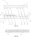
- Figure 3a illustrates a side view of a first embodiment of the backlighting assembly 11.
- a film 36 is adhered to the inner surface 22 of the first member 16.
- the light emitting device 12 emits a beam of light 14 which at least partially impinges on an inner surface 38 of the film 36 and at least partially impinges on the inner surface 20 of the second member 18.
- the film 36 is characterized by optical characteristics to provide light spectrum modification to the beam of light 14 creating a modified beam of light 40.
- the modified beam of light 40 then impinges on the inner surface 22 of the first member 16.
- the modified beam of light 40 transmits according to the first optical characteristics through the first member 16 to create a modified external beam of light 42.
- Figure 3b illustrates the modified external beam of light 42 visible through the outer surface 28 as a modified light spectrum color 44.
- the modified light spectrum color 44 is visually indistinguishable by an observer from the second light spectrum color 33 visible through the outer surface 30 creating a homogenized appearance.
- the second light spectrum color 33 from the second external beam of light 26 and modified light spectrum color 44 from the modified external beam of light 42 can be measured and compared using known color measuring techniques.
- the film 36 in combination with the first member 16 creates a stack which will produce the visually similar output light spectrum for the input beam of light 14 as compared to the output light spectrum of the second external beam of light 26 of the second member 18.
- the optical characteristics of the film 36 are determined by the first optical characteristics curve 34 as compared to the second optical characteristic curve 35.
- the optical characteristic variance 37 is the difference between the first optical characteristic curve 34 of the first member 16 and the second optical characteristic curve 35 of the second member 18 as shown in Figure 2 .
- the film 36 has film optical characteristics which when applied modify transmission of the first optical characteristic curve 34 to reach the second optical characteristic curve 35 and minimize the optical characteristic variance 37.
- the first optical characteristic curve 34 of the first member 16 transmits 870 of the light at 400 nm while the second optical characteristics curve 35 transmits 780 of the light at 400 nm ( Figure 2 ).
- the optical characteristic variance 37 is used along the visible light spectrum to determine the optical characteristics of the film 36 in the visible spectrum.
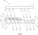
- Figure 4 is a side view through a second embodiment of a backlighting assembly 50.
- the film 36 has at least two layers with different optical characteristics to produce a modified beam of light 40.
- a first film layer 52 and a second film layer 53 with different material optical characteristics cooperate to provide the desired light spectrum modification to the beam of light 14.
- the beam of light 14 impinges on an inner surface 54 of the first film layer 52.
- a modified beam of light 56 is produced and impinges on the inner surface 55 of the second film layer 53.
- This modified beam of light 56 is further modified by the optical characteristics of the second film layer 53 to produce the modified beam of light 40 which impinges on the inner surface of the first member 16.
- the modified beam of light 40 passes through the first member 16 and is altered based on the material optical characteristics of the first member to produce a first external beam of light 42.
- the first external beam of light 42 produces a first color 44 as describe in reference to Figure 3 which is virtually indistinguishable from the second light spectrum color 33.
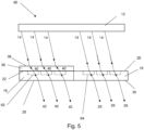
- FIG. 5 a side view of a third embodiment of a backlighting assembly 60 is illustrated.
- the first member 16 has at least one first member recess 62 and the second member 18 has at least one second member recess 64.
- the at least one first member recess 62 and the at least one second member recess 64 may be formed when the first member 16 and/or second member 18 are manufactured.
- the at least one first and/or second member recesses 62, 64 may be created after manufacturing of the first and/or second member 16, 18 by removing material such as with a laser etching process or the like.
- the film 36 is adhered to the inner surface 22 of the first member 16 and provides a light spectrum modification to the beam of light 14 to produce the modified beam of light 40 as described above in relation to Figure 2 , 3a and 3b .
- the first member 16 and the second member 18 are opaque.
- the at least one first member recess 62 and the at least one second member recess 64 provide a reduced thickness sections in the first and second members 16, 18 which are capable to transmit light and provide a backlight effect.
- the modified beam of light 40 is only transmittable through the at least one first member recess 62 and the beam of light 14 is only transmittable through the at least one second member recess 64.
- the at least one first member recess 62 and at least one second member recess 64 will provide a specific geometry or pattern of light to be visible through the outer surfaces 28, 30 when the light emitting device 12 is illuminated.
- the geometry or shape of the at least one first member recess 62 and the at least one second member recess 64 may be any configuration such as triangles, arrows, circles, logos, emblems or words as non-limiting examples.
- the optical characteristics of the film 36 is calculated as described in the example above for the first embodiment of the backlighting assembly 11.
- Figure 6 illustrates the third embodiment of the backlight assembly 60 when the light emitting device 12 (not shown) is not energized.
- Figure 7 illustrates the third embodiment of the backlight assembly 60 when the light emitting device 12 (not shown) is energized.
- the beam of light 14 is transmitted through the first and second members 16, 18 at the first and second member recesses 62, 64, the beam of light 14 produces the modified external beam of light 42 and the second external beam of light ( Figure 5 ).
- the at least one first member recess 62 and at least one second member recess 64 are shaped to produce a circular backlighting effect for each recess. This creates the homogenized pattern of light visible on the outer surfaces 28, 30.
- Figure 8 illustrates a fourth embodiment of the backlight assembly 70.
- the difference between optical characteristics of the first member and the optical characteristics of the second member may complex or produce transmittance curves which overlap as shown in Figure 9 .
- Utilizing a first member film 71 for light modification on first member 16 and a second member film 73 with different optical characteristics on the second member 18 may provide a less complex film solution for light spectrum modification than utilizing a film on a single member.
- the first member 16 has a first member film 71 applied to the inner surface 22 and the second member 18 has a second member film 73 applied to the inner surface 20.
- the beam of light 14 passes through the first member film 71 creating a modified beam of light 75 according to the optical characteristics of the first member film 71.
- This modified beam of light 75 impinges on the inner surface 22 of the first member and creates a first external beam of light 76.
- the beam of light 14 impinges of the second inner surface 74 of the second member film 73.
- the second member film 73 provides a second light spectrum modification different from the first member film 71 to the beam of light 14 producing a second modified beam of light 77.
- This second modified beam of light 77 impinges on the inner surface 20 of the second member 18.
- the modified beam of light 77 transmits through the second member 18 producing a second modified external beam of light 78.
- the first modified external beam of light 76 has a light spectrum color which produces a homogenized appearance with the light spectrum color from the second modified external beam of light 78.
- Figure 9 illustrates when the first member 16 optical characteristics and the second member 18 optical characteristics overlap at points in the visible light spectrum.
- the beam of light 14 will be altered by a first member film 71 before impinging on the first member 16 and by a second member film 73 before impinging on the second member 18.
- the use of the first member and second member films 71, 73 produces a homogenized color appearance between the first and second members 16, 18 for the backlighting assembly 70.
- the first member 16 has a third optical characteristic curve 79 and the second member 18 has fourth optical characteristic curve 80.
- the optical characteristics of the first member film 71 for the first member 16 is calculated based on the optical variance 82 which occurs when the third optical characteristic curve 79 has a higher transmittance percentage than the fourth optical characteristic curve 80 at a selected wavelength.
- the first member film 71 reduces the transmittance at a particular wavelength for the third optical characteristic curve to the transmittance rate of the fourth optical characteristic curve 80.
- the optical characteristics for the second member film 73 are calculated from the optical variance 84 which occurs when the fourth optical characteristic curve 80 has a higher transmittance percentage than the third optical characteristic curve 79 at a selected wavelength.
- the second member film 73 reduces the transmittance of the fourth optical characteristic curve 80 to the transmittance rate of the third optical characteristic curve 79.
- the first member film 71 in cooperation with the first member 16 and the second member film 73 in cooperation with the second member 18 create a combined optical characteristic curve 86 for the first and second members 16, 18. This combined optical characteristic curve 86 produces a homogenized external light appearance for the first and second members 16, 18 when the light emitting device 12 is energized.
Landscapes
- Engineering & Computer Science (AREA)
- General Engineering & Computer Science (AREA)
- Mechanical Engineering (AREA)
- Planar Illumination Modules (AREA)
Description
- The present invention is directed to a backlight assembly with components having different optical characteristics. Moreover, the present invention relates to a vehicle comprising such a backlight assembly.
- The statements in this section merely provide background information related to the present invention and may not constitute prior art.
- Backlight components are playing an increasingly important role in the interior and exterior design of a vehicle. Non-exhaustive examples of external cladding components which could be backlit are front grilles, side skirts, bumpers, tailgates and spoilers. Non-exhaustive examples of internal backlit components are instrument panels, door panels, center consoles and internal trims. Typically the backlit components are made by injection molding, however, within the present invention the components are not limited to injection molded parts and can for example be made of metal, glass or the like having optical light transmission characteristics.
- In order to enhance the operation safety, vehicles are being equipped with external cladding components utilized to display information outside the vehicle and interior components to provide lighting and display information. Backlighting through a component allows for displaying of information or lighting when the light source is energized. When the light source is not energized seamless uniform interior or exterior surface can be provided. When backlighting is used for two components with different optical characteristics arranged side by side, a visible color variation may occur between the light emitted from each component as viewed when the light source is illuminated. This is a result of the light transmitted through the dissimilar materials differently creating a non-homogenous appearance between the emitted light viewed from each component. The visible light color variation may be distracting and create an impression of poor quality or design.
-
US 2015/0210226 A1 discloses a vehicle trim element has a panel that includes at least one colored mask having solid areas and at least one aperture delimiting a pattern, and a colored screen transmitting light and closing each aperture of the mask. Further documents disclosing the relevant prior art areEP 1 839 945 A1 ,US 6 31 8 872 B1 andUS 2004/239750 A1 .It is one task of the present invention to present a vehicle backlighting assembly with at least two components having different optical characteristics to produce a homogeneous light appearance when the light emitting device is turned on and a homogeneous surface appearance when the light emitting device is turned off. - According to an embodiment a backlighting assembly for a vehicle, comprises
- a first member, wherein the first member has a first optical characteristic curve which is the transmittance percentage in function of the wavelength;
- a second member adjacent to the first member, wherein the second member has a second optical characteristic curve which is the transmittance percentage in function of the wavelength, the second optical characteristic curve differing from the first optical characteristic curve;
- the first member and the second member being arranged side by side;
- a film adhered to the first member; and
- a light emitting device emitting a beam of light, wherein the light emitting device is positioned for a beam of light to partially impinge on the second member and partially impinge the film;
- wherein the film provides light spectrum modification of the beam of light from the light emitting device across the visible light spectrum to create a modified beam of light which impinges the first member;
- wherein the light spectrum modification is determined from a transmittance variance between the first optical characteristic curve of the first member and the second optical characteristic curve of the second member such that a common light emitting device can be used for both members where the output transmitted light through the first and second members has a homogenized appearance for an observer.
- The film provides a light spectrum modification to the light impinging on the first member by altering the beam of light from the light source before the light impinges the first member. This modification allows a common light source to be used for both members where the output transmitted light through the first and second members has a homogenized appearance.
- In accordance with a further embodiment the light spectrum modification may be an optical characteristic to absorb and/or reflect a selected light spectrum.
- The appearance of the backlight spectrum visible through the first member is to be homogenous with the backlight spectrum through the second member. The film provides a light spectrum modification to the light impinging on the first member to correct the output backlight spectrum visible through the first member. In order to provide the light spectrum modification, the film reduces and/or eliminates a determined light spectrum from reaching the surface of the first member. The film is chosen with an optical characteristic to absorb and/or reflect a determined light spectrum to prevent this determined light spectrum from impinging the inner surface of the first member.
- According to another embodiment the light spectrum modification is determined from a transmittance variance between the first optical characteristic of the first member and the second optical characteristic of the second member.
- Determining the transmittance variance between the emitted backlight spectrum though the first member compared to the backlight spectrum of the second member indicates where the optical characteristics of the first member deviate from the optical characteristics of the second member. The film optical characteristics are then chosen to using the transmittance variance between the light spectrum of the first member and the second member. The film optical characteristics in combination with the optical characteristics of the first member will produce a backlight spectrum to be visually indistinguishable from the backlight spectrum of the second member.
- According to another embodiment the film further comprises at least two film layers to provide the light spectrum modification
- The optical characteristics needed to provide the light spectrum modification to the beam of light may be complex. When the complexity of the modification is increased, a single film may not have all the optical characteristics to provide the entire desired light modification. A film with at least two film layers, each having different optical characteristics, may cooperate to provide the desired light spectrum modification.
- According to another embodiment, the first member and the second member are opaque with at least one light transmitting recess.
- Backlighting can be used to display information on the surface. By having opaque areas and light transmitting recesses, information can be displayed in graphic form on the surface of the first and second members when the light source is energized.
- According to another embodiment the at least one light transmitting recess is a circle, triangle, arrow, logo, emblem or words.
- The light transmitting recess can be shaped based to display backlit information in recognizable form. Circles, triangles, arrows, logos, emblems and words are all recognizable shapes which can convey information when illuminated.
- In accordance with a further embodiment the light emitting device is at least one light emitting diode (LED) source.
- Light emitting diodes may be used in some applications. They provide a low heat light source and can be packaged with few constraints.
- According to another embodiment the backlighting assembly further comprises a second film adhered to the second member, wherein the second film provides a second light spectrum modification of the beam of light from the light emitting device to create a second modified beam of light which impinges the second member.
- In some applications, the difference between optical characteristics of the first member and the optical characteristics of the second member may complex or produce transmittance curves which overlap. Utilizing a film on the first member to provide a light modification in cooperation with a second film on the second member to provide a second light modification may provide a less complex solution for light spectrum modification than utilizing a film on the first member alone.
- In accordance with a further embodiment the first member and the second member may be interior or exterior components.
- Interior and exterior components may have a backlighting component which occurs through two components located side by side. The use of light spectrum modification to provide a homogenized output light spectrum may be applied to any multicomponent backlighting assembly.
- It should be noted that the features set out individually in the following description can be combined with each other in any technically advantageous manner and set out other forms of the present invention. It should be understood, however, that the disclosure is not limited to the precise arrangements and instrumentalities shown. The accompanying drawings, which are incorporated in and constitute a part of this specification, illustrate an implementation of system, apparatuses, and methods consistent with the present description and, together with the description, serve to explain advantages and principles consistent with the disclosure. The figures are not necessarily drawn to scale. Like numbers used in the figures refer to like components. However, it will be understood that the use of a number to refer to a component in a given figure is not intended to limit the component in another figure labelled with the same number. The description further characterizes and specifies the present invention in particular in connection with the figures.
- In order that the disclosure may be well understood, there will now be described various forms thereof, given by way of example, reference being made to the accompanying drawings, in which:
-
Figure 1a is a side view through an existing backlighting assembly, -
Figure 1b is a front view of an existing illuminated backlighting assembly, -
Figure 2 is a graphical representation of the optical characteristics of the components ofFigure 1a , -
Figure 3a is a side view through a first embodiment of a backlighting assembly according to the present invention, -
Figure 3b is a front view of an illuminated backlighting assembly according to the present invention, -
Figure 4 is a side view through a second embodiment of a backlighting assembly according to the present invention, -
Figure 5 is a side view through a third embodiment of a backlighting assembly according to the present invention, -
Figure 6 is a front view of a non-illuminated backlighting assembly for external cladding components according to the present invention, -
Figure 7 is a front view of an illuminated backlighting assembly for external cladding components according to the present invention, -
Figure 8 is a fourth embodiment of a backlighting assembly according to the present invention, and -
Figure 9 is a graphical representation to achieve a homogenized output light appearance for the third embodiment according to the present invention. - The following description is merely exemplary in nature and is not intended to limit the present invention, application, or uses. It should be understood that throughout the drawings, corresponding reference numerals indicate like or corresponding parts and features.
-
Figure 1a illustrates a side view of an existingbacklighting assembly 10 according to the prior art. Alight emitting device 12 emits a beam of light 14 which at least partially impinges on aninner surface 22 of afirst member 16 and at least partially impinges on aninner surface 20 of asecond member 18. Thefirst member 16 is arranged side by side to thesecond member 18 inFigure 1 . The first andsecond members second members light emitting device 12 may be a light emitting diode (LED) source. Thelight emitting device 12 may also have multiple light sources (not shown). Thelight emitting device 12 may also contain a light guide with one or more LED's coupled to the light guide where the light guide could be of a material with light transmission properties such as PMMA, PC, or glass as non-limiting examples. - The material optical characteristics of the
first member 16 are dissimilar from the material optical characteristics across the light spectrum of the second member 18 (Figure 2 ). Optical characteristics include transmissivity, reflectivity and absorptivity. Therefore when the beam oflight 14 impinges on the inner surface 22 a portion of the beam oflight 14 may be reflected and/or absorbed and/or transmitted through the material of thefirst member 16. The beam oflight 14 is transmitted through thefirst member 16 according to its optical characteristics producing a first external beam of light 24 with a first light spectrum visible through theouter surface 28. In one example, thefirst member 16 may absorb a particular light spectrum as the beam of light 14 passes through thefirst member 16. - Similarly, when the beam of
light 14 impinges theinner surface 20 of thesecond member 18, a second external beam of light 26 with a second light spectrum visible through anouter surface 30 is created by the material optical characteristics of thesecond member 18. In particular, the output light spectrum contrast between the first and second external beams oflight second member 18 which is not absorbed by the material of thefirst member 16 as the beam oflight 14 is transmitted through the different optical characteristics of the first andsecond members light 24 is viewed as a firstlight spectrum color 32 and the second external beam oflight 26 is viewed as a secondlight spectrum color 33.Figure 1b illustrates the visible contrast between the firstlight spectrum color 32 visible through theouter surface 28 and the secondlight spectrum color 33 visible through theouter surface 30. This contrast is created by the different optical characteristics between thefirst member 16 material and thesecond member 18 material. The contrast in light spectrum colors creates a non-homogenized appearance in thebacklighting assembly 10 viewing when thelight emitting device 12 is energized. As illustrated inFigure 1b , the firstlight spectrum color 32 is visibly distinct from the secondlight spectrum color 33 which may detract from the overall design aesthetic and/or give the impression of poor quality. -
Figure 2 illustrates an exemplary graphical representation of a first opticalcharacteristic curve 34 for thefirst member 16 and a second opticalcharacteristic curve 35 for the second member 18 (Figure 1a ). The first and second opticalcharacteristic curves characteristic curve 34 has distinct optical characteristics over the visible light spectrum when compared to the second opticalcharacteristic curve 35 creating an opticalcharacteristic variance 37. It is the opticalcharacteristic variance 37 which produces the non-homogenized appearance between the firstlight spectrum color 32 and the secondlight spectrum color 33. -
Figure 3a illustrates a side view of a first embodiment of thebacklighting assembly 11. Afilm 36 is adhered to theinner surface 22 of thefirst member 16. Thelight emitting device 12 emits a beam of light 14 which at least partially impinges on aninner surface 38 of thefilm 36 and at least partially impinges on theinner surface 20 of thesecond member 18. Thefilm 36 is characterized by optical characteristics to provide light spectrum modification to the beam of light 14 creating a modified beam oflight 40. The modified beam of light 40 then impinges on theinner surface 22 of thefirst member 16. The modified beam of light 40 transmits according to the first optical characteristics through thefirst member 16 to create a modified external beam oflight 42. -
Figure 3b illustrates the modified external beam of light 42 visible through theouter surface 28 as a modifiedlight spectrum color 44. The modifiedlight spectrum color 44 is visually indistinguishable by an observer from the secondlight spectrum color 33 visible through theouter surface 30 creating a homogenized appearance. The secondlight spectrum color 33 from the second external beam oflight 26 and modifiedlight spectrum color 44 from the modified external beam of light 42 can be measured and compared using known color measuring techniques. - The
film 36 in combination with thefirst member 16 creates a stack which will produce the visually similar output light spectrum for the input beam of light 14 as compared to the output light spectrum of the second external beam oflight 26 of thesecond member 18. - The optical characteristics of the
film 36 are determined by the first optical characteristics curve 34 as compared to the second opticalcharacteristic curve 35. The opticalcharacteristic variance 37 is the difference between the first opticalcharacteristic curve 34 of thefirst member 16 and the second opticalcharacteristic curve 35 of thesecond member 18 as shown inFigure 2 . Utilizing the exemplary first and second opticalcharacteristic curves Figure 2 , thefilm 36 has film optical characteristics which when applied modify transmission of the first opticalcharacteristic curve 34 to reach the second opticalcharacteristic curve 35 and minimize the opticalcharacteristic variance 37. An exemplary calculation for the film optical characteristics based on the first and second opticalcharacteristic curves
The first opticalcharacteristic curve 34 of thefirst member 16 transmits 870 of the light at 400 nm while the second optical characteristics curve 35 transmits 780 of the light at 400 nm (Figure 2 ). - The film optical characteristics are selected to modify the 87% transmittal rate of the
first member 16 to match the 780 transmittal rate through thesecond member 18. Therefore, thefilm 36 with 90% transmittance rate at 400 nm is applied on thefirst member 16 to reduce the transmittance rate of thefirst member 16. (90% x 870 = 78%). The opticalcharacteristic variance 37 is used along the visible light spectrum to determine the optical characteristics of thefilm 36 in the visible spectrum. -
Figure 4 is a side view through a second embodiment of abacklighting assembly 50. In this second embodiment, thefilm 36 has at least two layers with different optical characteristics to produce a modified beam oflight 40. Afirst film layer 52 and asecond film layer 53 with different material optical characteristics cooperate to provide the desired light spectrum modification to the beam oflight 14. The beam oflight 14 impinges on aninner surface 54 of thefirst film layer 52. As the beam oflight 14 is transmitted through the film layer 52 a modified beam oflight 56 is produced and impinges on theinner surface 55 of thesecond film layer 53. This modified beam oflight 56 is further modified by the optical characteristics of thesecond film layer 53 to produce the modified beam of light 40 which impinges on the inner surface of thefirst member 16. The modified beam of light 40 passes through thefirst member 16 and is altered based on the material optical characteristics of the first member to produce a first external beam oflight 42. The first external beam oflight 42 produces afirst color 44 as describe in reference toFigure 3 which is virtually indistinguishable from the secondlight spectrum color 33. - In
Figure 5 , a side view of a third embodiment of abacklighting assembly 60 is illustrated. Thefirst member 16 has at least onefirst member recess 62 and thesecond member 18 has at least onesecond member recess 64. The at least onefirst member recess 62 and the at least onesecond member recess 64 may be formed when thefirst member 16 and/orsecond member 18 are manufactured. Alternatively, the at least one first and/or second member recesses 62, 64 may be created after manufacturing of the first and/orsecond member film 36 is adhered to theinner surface 22 of thefirst member 16 and provides a light spectrum modification to the beam of light 14 to produce the modified beam of light 40 as described above in relation toFigure 2 ,3a and 3b . In this embodiment, thefirst member 16 and thesecond member 18 are opaque. The at least onefirst member recess 62 and the at least onesecond member recess 64 provide a reduced thickness sections in the first andsecond members light 40 is only transmittable through the at least onefirst member recess 62 and the beam oflight 14 is only transmittable through the at least onesecond member recess 64. The at least onefirst member recess 62 and at least onesecond member recess 64 will provide a specific geometry or pattern of light to be visible through theouter surfaces light emitting device 12 is illuminated. The geometry or shape of the at least onefirst member recess 62 and the at least onesecond member recess 64 may be any configuration such as triangles, arrows, circles, logos, emblems or words as non-limiting examples. The optical characteristics of thefilm 36 is calculated as described in the example above for the first embodiment of thebacklighting assembly 11. -
Figure 6 illustrates the third embodiment of thebacklight assembly 60 when the light emitting device 12 (not shown) is not energized. When thelight emitting device 12 is not energized, the appearance on theouter surfaces Figure 7 illustrates the third embodiment of thebacklight assembly 60 when the light emitting device 12 (not shown) is energized. When the beam oflight 14 is transmitted through the first andsecond members light 14 produces the modified external beam oflight 42 and the second external beam of light (Figure 5 ). In this variation, the at least onefirst member recess 62 and at least onesecond member recess 64 are shaped to produce a circular backlighting effect for each recess. This creates the homogenized pattern of light visible on theouter surfaces -
Figure 8 illustrates a fourth embodiment of thebacklight assembly 70. In some applications, the difference between optical characteristics of the first member and the optical characteristics of the second member may complex or produce transmittance curves which overlap as shown inFigure 9 . Utilizing afirst member film 71 for light modification onfirst member 16 and asecond member film 73 with different optical characteristics on thesecond member 18 may provide a less complex film solution for light spectrum modification than utilizing a film on a single member. In this variation, thefirst member 16 has afirst member film 71 applied to theinner surface 22 and thesecond member 18 has asecond member film 73 applied to theinner surface 20. The beam of light 14 passes through thefirst member film 71 creating a modified beam of light 75 according to the optical characteristics of thefirst member film 71. This modified beam oflight 75 impinges on theinner surface 22 of the first member and creates a first external beam oflight 76. The beam oflight 14 impinges of the secondinner surface 74 of thesecond member film 73. Thesecond member film 73 provides a second light spectrum modification different from thefirst member film 71 to the beam of light 14 producing a second modified beam oflight 77. This second modified beam oflight 77 impinges on theinner surface 20 of thesecond member 18. The modified beam of light 77 transmits through thesecond member 18 producing a second modified external beam oflight 78. The first modified external beam oflight 76 has a light spectrum color which produces a homogenized appearance with the light spectrum color from the second modified external beam oflight 78. -
Figure 9 illustrates when thefirst member 16 optical characteristics and thesecond member 18 optical characteristics overlap at points in the visible light spectrum. When this variation occurs, the beam oflight 14 will be altered by afirst member film 71 before impinging on thefirst member 16 and by asecond member film 73 before impinging on thesecond member 18. The use of the first member andsecond member films second members backlighting assembly 70. In this variation, thefirst member 16 has a third opticalcharacteristic curve 79 and thesecond member 18 has fourth opticalcharacteristic curve 80. The optical characteristics of thefirst member film 71 for thefirst member 16 is calculated based on theoptical variance 82 which occurs when the third opticalcharacteristic curve 79 has a higher transmittance percentage than the fourth opticalcharacteristic curve 80 at a selected wavelength. Thefirst member film 71 reduces the transmittance at a particular wavelength for the third optical characteristic curve to the transmittance rate of the fourth opticalcharacteristic curve 80. - The optical characteristics for the
second member film 73 are calculated from theoptical variance 84 which occurs when the fourth opticalcharacteristic curve 80 has a higher transmittance percentage than the third opticalcharacteristic curve 79 at a selected wavelength. Thesecond member film 73 reduces the transmittance of the fourth opticalcharacteristic curve 80 to the transmittance rate of the third opticalcharacteristic curve 79. Thefirst member film 71 in cooperation with thefirst member 16 and thesecond member film 73 in cooperation with thesecond member 18 create a combined opticalcharacteristic curve 86 for the first andsecond members characteristic curve 86 produces a homogenized external light appearance for the first andsecond members light emitting device 12 is energized. - The foregoing description of various preferred embodiments have been presented for purposes of illustration and description. It is not intended to be exhaustive or to limit the invention to the precise forms disclosed, and obviously many modifications and variations are possible within the scope of the appended claims. The example embodiments, as described above, were chosen and described in order to best explain the principles of the invention and its practical application to thereby enable others skilled in the art to best utilize the invention in various embodiments and with various modifications as are suited to the particular use contemplated.
-
- 10 - Backlighting Assembly according to the prior art
- 11 - Backlighting Assembly according to a first embodiment
- 12 - Light Emitting Device
- 14 - Beam of Light
- 16 - First Member
- 18 - Second Member
- 20 - Inner Surface of the Second Member
- 22 - Inner Surface of the First Member
- 24 - First External Beam of Light
- 26 - Second External Beam of Light
- 28 - Outer Surface of the First Member
- 30 - Outer Surface of the Second Member
- 32 - First Light spectrum Color
- 33 - Second Light spectrum Color
- 34 - First Optical Characteristic Curve
- 35 - Second Optical Characteristic Curve
- 36 - Film
- 37 - Optical Characteristic Variance
- 38 - Inner Surface of Film
- 40 - Modified Beam of Light
- 42 - Modified External Beam of Light
- 44 - Modified Light spectrum Color
- 50 - Backlighting Assembly according to a second embodiment
- 52 - First Film Layer
- 53 - Second Film Layer
- 54 - Inner surface of the First Film Layer
- 55 - Inner Surface of the Second Film Layer
- 56 - Modified Beam of Light
- 58 - Modified Beam of Light
- 60 - 102 - Backlighting Assembly according to a third embodiment
- 62 - 46 - First Member Recess
- 64 - 48 - Second Member Recess
- 70 - Backlighting Assembly according to a fourth embodiment
- 71 - First Member Film
- 72 - Inner Surface of First Member Film
- 73 - Second Member Film
- 74 - Inner Surface of Second Member Film
- 75 - First Modified Beam of Light
- 76 - First Modified External Beam of Light
- 77 - Second Modified Beam of Light
- 78 - Second Modified External Beam of Light
- 79 - Third Optical Characteristic Curve
- 80 - Fourth Optical Characteristic Curve
- 82 - Optical Variance
- 84 - Optical Variance
- 86 - Combined Optical Characteristic Curve
Claims (8)
- A backlighting assembly (11) for a vehicle, comprising:- a first member (16), wherein the first member (16) has a first optical characteristic curve (34) which is the transmittance percentage in function of the wavelength;- a second member (18) adjacent to the first member (16), wherein the second member (18) has a second optical characteristic curve (35) which is the transmittance percentage in function of the wavelength, the second optical characteristic curve (35) differing from the first optical characteristic curve (34);- the first member (16) and the second member (18) being arranged side by side;- a film (36) adhered to the first member (16); and- a light emitting device (12) emitting a beam of light (14), wherein the light emitting device (12) is positioned for a beam of light (14) to partially impinge on the second member (18) and partially impinge the film (36);- wherein the film (36) provides light spectrum modification of the beam of light (14) from the light emitting device (12) across the visible light spectrum to create a modified beam of light (40) which impinges the first member (16); and- wherein the light spectrum modification is determined from a transmittance variance between the first optical characteristic curve (34) of the first member (16) and the second optical characteristic curve (35) of the second member (18) such that a common light emitting device (12) can be used for both members (16,18) where the output transmitted light through the first and second members (16,18) has a homogenized appearance for an observer.
- The backlighting assembly (11) according to claim 1 wherein the light spectrum modification is an optical characteristic to absorb and/or reflect a selected light spectrum.
- The backlighting assembly (11) according claim 1 wherein the film (36) further comprises at least two film layers (52, 53) to provide the light spectrum modification.
- The backlighting assembly (11) according to claim 1 wherein the first member (16) and the second member (18) are opaque with at least one light transmitting recess (62, 64) .
- The backlighting assembly (11) according to claim 4, wherein the at least one light transmitting recess (62, 64) is a circle, triangle, arrow, logo, emblem or words.
- The backlighting assembly (11) according to claim 1 wherein the light emitting device (12) is at least one light emitting diode (LED) source.
- The backlighting assembly (11) according to claim 1 further comprising a second film (71) adhered to the second member (18), wherein the second film (71) provides a second light spectrum modification of the beam of light (14) from the light emitting device (12) to create a second modified beam of light (74) which impinges the second member (18).
- The backlighting assembly (11) according to claim 1, wherein the first member (16) and the second member (18) are interior or exterior components.
Priority Applications (2)
| Application Number | Priority Date | Filing Date | Title |
|---|---|---|---|
| ES21157803T ES2977815T3 (en) | 2021-02-18 | 2021-02-18 | Backlight assembly for components with variable optical characteristics |
| EP21157803.4A EP4046869B1 (en) | 2021-02-18 | 2021-02-18 | Backlight assembly for varying optical characteristic components |
Applications Claiming Priority (1)
| Application Number | Priority Date | Filing Date | Title |
|---|---|---|---|
| EP21157803.4A EP4046869B1 (en) | 2021-02-18 | 2021-02-18 | Backlight assembly for varying optical characteristic components |
Publications (2)
| Publication Number | Publication Date |
|---|---|
| EP4046869A1 EP4046869A1 (en) | 2022-08-24 |
| EP4046869B1 true EP4046869B1 (en) | 2024-02-14 |
Family
ID=74668660
Family Applications (1)
| Application Number | Title | Priority Date | Filing Date |
|---|---|---|---|
| EP21157803.4A Active EP4046869B1 (en) | 2021-02-18 | 2021-02-18 | Backlight assembly for varying optical characteristic components |
Country Status (2)
| Country | Link |
|---|---|
| EP (1) | EP4046869B1 (en) |
| ES (1) | ES2977815T3 (en) |
Family Cites Families (5)
| Publication number | Priority date | Publication date | Assignee | Title |
|---|---|---|---|---|
| JP4186362B2 (en) * | 1999-05-25 | 2008-11-26 | 株式会社デンソー | Instrument |
| DE10141751A1 (en) * | 2001-08-29 | 2003-03-27 | Siemens Ag | Production method for display dial, especially for motor vehicle use, lacquers outer surface of base, produces markings by laser removal of lacquer surface |
| JP4993985B2 (en) * | 2006-03-30 | 2012-08-08 | カルソニックカンセイ株式会社 | Variable display structure |
| FR3016839B1 (en) * | 2014-01-27 | 2017-06-09 | Faurecia Interieur Ind | VEHICLE CLUTCH ELEMENT |
| JP6786302B2 (en) * | 2016-08-12 | 2020-11-18 | 株式会社小糸製作所 | Lighting device |
-
2021
- 2021-02-18 ES ES21157803T patent/ES2977815T3/en active Active
- 2021-02-18 EP EP21157803.4A patent/EP4046869B1/en active Active
Also Published As
| Publication number | Publication date |
|---|---|
| EP4046869A1 (en) | 2022-08-24 |
| ES2977815T3 (en) | 2024-08-30 |
Similar Documents
| Publication | Publication Date | Title |
|---|---|---|
| US11745671B2 (en) | Backlit vehicle interior panel with specialty materials | |
| US7216997B2 (en) | Phosphor reactive instrument panel and gauges | |
| JP6427006B2 (en) | Device for viewing images on laminated substrates | |
| US8591051B2 (en) | Panel and method for producing the same | |
| US10513222B2 (en) | Motor vehicle trim part with illumination | |
| US10269330B2 (en) | Vehicle interior equipment with a screen, corresponding management process | |
| CN102901020B (en) | Laser forming baffle plate | |
| JP2015513684A5 (en) | ||
| US10789865B2 (en) | Display element with transition lamination of partial films and coatings | |
| EP3802218A1 (en) | Trim element which can be backlit, for a vehicle | |
| US20200039431A1 (en) | Molded part and method for manufacturing such a molded part | |
| CN220038269U (en) | Vehicle ornament | |
| EP3908481B1 (en) | Covering device, body part and motor vehicle | |
| US12568719B2 (en) | Display device and method of manufacturing display device | |
| US9643532B2 (en) | Method for producing a light for vehicles and exterior mirror assembly of a vehicle with a lamp thus prepared | |
| EP3376098B1 (en) | Display apparatus | |
| US7278748B2 (en) | Display apparatus | |
| EP3184363B1 (en) | Lighting device for an interior panel of a vehicle | |
| US20200355340A1 (en) | Warning light for blind area of lane change | |
| JP5820286B2 (en) | Automotive lighting plate | |
| CN115503473A (en) | Function display and associated operating elements for optionally displaying at least one symbol representing a switching function and/or a plurality of switching states | |
| EP4046869B1 (en) | Backlight assembly for varying optical characteristic components | |
| US8101265B2 (en) | Combination instrument | |
| JP2002156925A (en) | Display plate | |
| JP2008185753A (en) | Display device |
Legal Events
| Date | Code | Title | Description |
|---|---|---|---|
| PUAI | Public reference made under article 153(3) epc to a published international application that has entered the european phase |
Free format text: ORIGINAL CODE: 0009012 |
|
| STAA | Information on the status of an ep patent application or granted ep patent |
Free format text: STATUS: THE APPLICATION HAS BEEN PUBLISHED |
|
| AK | Designated contracting states |
Kind code of ref document: A1 Designated state(s): AL AT BE BG CH CY CZ DE DK EE ES FI FR GB GR HR HU IE IS IT LI LT LU LV MC MK MT NL NO PL PT RO RS SE SI SK SM TR |
|
| STAA | Information on the status of an ep patent application or granted ep patent |
Free format text: STATUS: REQUEST FOR EXAMINATION WAS MADE |
|
| 17P | Request for examination filed |
Effective date: 20230216 |
|
| RBV | Designated contracting states (corrected) |
Designated state(s): AL AT BE BG CH CY CZ DE DK EE ES FI FR GB GR HR HU IE IS IT LI LT LU LV MC MK MT NL NO PL PT RO RS SE SI SK SM TR |
|
| P01 | Opt-out of the competence of the unified patent court (upc) registered |
Effective date: 20230427 |
|
| GRAP | Despatch of communication of intention to grant a patent |
Free format text: ORIGINAL CODE: EPIDOSNIGR1 |
|
| STAA | Information on the status of an ep patent application or granted ep patent |
Free format text: STATUS: GRANT OF PATENT IS INTENDED |
|
| INTG | Intention to grant announced |
Effective date: 20231030 |
|
| GRAS | Grant fee paid |
Free format text: ORIGINAL CODE: EPIDOSNIGR3 |
|
| GRAA | (expected) grant |
Free format text: ORIGINAL CODE: 0009210 |
|
| STAA | Information on the status of an ep patent application or granted ep patent |
Free format text: STATUS: THE PATENT HAS BEEN GRANTED |
|
| AK | Designated contracting states |
Kind code of ref document: B1 Designated state(s): AL AT BE BG CH CY CZ DE DK EE ES FI FR GB GR HR HU IE IS IT LI LT LU LV MC MK MT NL NO PL PT RO RS SE SI SK SM TR |
|
| REG | Reference to a national code |
Ref country code: GB Ref legal event code: FG4D |
|
| REG | Reference to a national code |
Ref country code: CH Ref legal event code: EP |
|
| REG | Reference to a national code |
Ref country code: DE Ref legal event code: R096 Ref document number: 602021009270 Country of ref document: DE |
|
| REG | Reference to a national code |
Ref country code: IE Ref legal event code: FG4D |
|
| REG | Reference to a national code |
Ref country code: LT Ref legal event code: MG9D |
|
| REG | Reference to a national code |
Ref country code: NL Ref legal event code: MP Effective date: 20240214 |
|
| PG25 | Lapsed in a contracting state [announced via postgrant information from national office to epo] |
Ref country code: IS Free format text: LAPSE BECAUSE OF FAILURE TO SUBMIT A TRANSLATION OF THE DESCRIPTION OR TO PAY THE FEE WITHIN THE PRESCRIBED TIME-LIMIT Effective date: 20240614 |
|
| PG25 | Lapsed in a contracting state [announced via postgrant information from national office to epo] |
Ref country code: LT Free format text: LAPSE BECAUSE OF FAILURE TO SUBMIT A TRANSLATION OF THE DESCRIPTION OR TO PAY THE FEE WITHIN THE PRESCRIBED TIME-LIMIT Effective date: 20240214 |
|
| PG25 | Lapsed in a contracting state [announced via postgrant information from national office to epo] |
Ref country code: GR Free format text: LAPSE BECAUSE OF FAILURE TO SUBMIT A TRANSLATION OF THE DESCRIPTION OR TO PAY THE FEE WITHIN THE PRESCRIBED TIME-LIMIT Effective date: 20240515 |
|
| REG | Reference to a national code |
Ref country code: AT Ref legal event code: MK05 Ref document number: 1656785 Country of ref document: AT Kind code of ref document: T Effective date: 20240214 |
|
| PG25 | Lapsed in a contracting state [announced via postgrant information from national office to epo] |
Ref country code: HR Free format text: LAPSE BECAUSE OF FAILURE TO SUBMIT A TRANSLATION OF THE DESCRIPTION OR TO PAY THE FEE WITHIN THE PRESCRIBED TIME-LIMIT Effective date: 20240214 Ref country code: NL Free format text: LAPSE BECAUSE OF FAILURE TO SUBMIT A TRANSLATION OF THE DESCRIPTION OR TO PAY THE FEE WITHIN THE PRESCRIBED TIME-LIMIT Effective date: 20240214 Ref country code: RS Free format text: LAPSE BECAUSE OF FAILURE TO SUBMIT A TRANSLATION OF THE DESCRIPTION OR TO PAY THE FEE WITHIN THE PRESCRIBED TIME-LIMIT Effective date: 20240514 |
|
| PG25 | Lapsed in a contracting state [announced via postgrant information from national office to epo] |
Ref country code: AT Free format text: LAPSE BECAUSE OF FAILURE TO SUBMIT A TRANSLATION OF THE DESCRIPTION OR TO PAY THE FEE WITHIN THE PRESCRIBED TIME-LIMIT Effective date: 20240214 |
|
| PG25 | Lapsed in a contracting state [announced via postgrant information from national office to epo] |
Ref country code: RS Free format text: LAPSE BECAUSE OF FAILURE TO SUBMIT A TRANSLATION OF THE DESCRIPTION OR TO PAY THE FEE WITHIN THE PRESCRIBED TIME-LIMIT Effective date: 20240514 Ref country code: NO Free format text: LAPSE BECAUSE OF FAILURE TO SUBMIT A TRANSLATION OF THE DESCRIPTION OR TO PAY THE FEE WITHIN THE PRESCRIBED TIME-LIMIT Effective date: 20240514 Ref country code: NL Free format text: LAPSE BECAUSE OF FAILURE TO SUBMIT A TRANSLATION OF THE DESCRIPTION OR TO PAY THE FEE WITHIN THE PRESCRIBED TIME-LIMIT Effective date: 20240214 Ref country code: LT Free format text: LAPSE BECAUSE OF FAILURE TO SUBMIT A TRANSLATION OF THE DESCRIPTION OR TO PAY THE FEE WITHIN THE PRESCRIBED TIME-LIMIT Effective date: 20240214 Ref country code: IS Free format text: LAPSE BECAUSE OF FAILURE TO SUBMIT A TRANSLATION OF THE DESCRIPTION OR TO PAY THE FEE WITHIN THE PRESCRIBED TIME-LIMIT Effective date: 20240614 Ref country code: HR Free format text: LAPSE BECAUSE OF FAILURE TO SUBMIT A TRANSLATION OF THE DESCRIPTION OR TO PAY THE FEE WITHIN THE PRESCRIBED TIME-LIMIT Effective date: 20240214 Ref country code: GR Free format text: LAPSE BECAUSE OF FAILURE TO SUBMIT A TRANSLATION OF THE DESCRIPTION OR TO PAY THE FEE WITHIN THE PRESCRIBED TIME-LIMIT Effective date: 20240515 Ref country code: FI Free format text: LAPSE BECAUSE OF FAILURE TO SUBMIT A TRANSLATION OF THE DESCRIPTION OR TO PAY THE FEE WITHIN THE PRESCRIBED TIME-LIMIT Effective date: 20240214 Ref country code: BG Free format text: LAPSE BECAUSE OF FAILURE TO SUBMIT A TRANSLATION OF THE DESCRIPTION OR TO PAY THE FEE WITHIN THE PRESCRIBED TIME-LIMIT Effective date: 20240214 Ref country code: AT Free format text: LAPSE BECAUSE OF FAILURE TO SUBMIT A TRANSLATION OF THE DESCRIPTION OR TO PAY THE FEE WITHIN THE PRESCRIBED TIME-LIMIT Effective date: 20240214 |
|
| PG25 | Lapsed in a contracting state [announced via postgrant information from national office to epo] |
Ref country code: PL Free format text: LAPSE BECAUSE OF FAILURE TO SUBMIT A TRANSLATION OF THE DESCRIPTION OR TO PAY THE FEE WITHIN THE PRESCRIBED TIME-LIMIT Effective date: 20240214 Ref country code: PT Free format text: LAPSE BECAUSE OF FAILURE TO SUBMIT A TRANSLATION OF THE DESCRIPTION OR TO PAY THE FEE WITHIN THE PRESCRIBED TIME-LIMIT Effective date: 20240614 |
|
| PG25 | Lapsed in a contracting state [announced via postgrant information from national office to epo] |
Ref country code: SE Free format text: LAPSE BECAUSE OF FAILURE TO SUBMIT A TRANSLATION OF THE DESCRIPTION OR TO PAY THE FEE WITHIN THE PRESCRIBED TIME-LIMIT Effective date: 20240214 Ref country code: PT Free format text: LAPSE BECAUSE OF FAILURE TO SUBMIT A TRANSLATION OF THE DESCRIPTION OR TO PAY THE FEE WITHIN THE PRESCRIBED TIME-LIMIT Effective date: 20240614 Ref country code: PL Free format text: LAPSE BECAUSE OF FAILURE TO SUBMIT A TRANSLATION OF THE DESCRIPTION OR TO PAY THE FEE WITHIN THE PRESCRIBED TIME-LIMIT Effective date: 20240214 Ref country code: LV Free format text: LAPSE BECAUSE OF FAILURE TO SUBMIT A TRANSLATION OF THE DESCRIPTION OR TO PAY THE FEE WITHIN THE PRESCRIBED TIME-LIMIT Effective date: 20240214 |
|
| REG | Reference to a national code |
Ref country code: ES Ref legal event code: FG2A Ref document number: 2977815 Country of ref document: ES Kind code of ref document: T3 Effective date: 20240830 |
|
| REG | Reference to a national code |
Ref country code: CH Ref legal event code: PL |
|
| PG25 | Lapsed in a contracting state [announced via postgrant information from national office to epo] |
Ref country code: DK Free format text: LAPSE BECAUSE OF FAILURE TO SUBMIT A TRANSLATION OF THE DESCRIPTION OR TO PAY THE FEE WITHIN THE PRESCRIBED TIME-LIMIT Effective date: 20240214 |
|
| PG25 | Lapsed in a contracting state [announced via postgrant information from national office to epo] |
Ref country code: SM Free format text: LAPSE BECAUSE OF FAILURE TO SUBMIT A TRANSLATION OF THE DESCRIPTION OR TO PAY THE FEE WITHIN THE PRESCRIBED TIME-LIMIT Effective date: 20240214 |
|
| PG25 | Lapsed in a contracting state [announced via postgrant information from national office to epo] |
Ref country code: LU Free format text: LAPSE BECAUSE OF NON-PAYMENT OF DUE FEES Effective date: 20240218 |
|
| PG25 | Lapsed in a contracting state [announced via postgrant information from national office to epo] |
Ref country code: CH Free format text: LAPSE BECAUSE OF NON-PAYMENT OF DUE FEES Effective date: 20240229 |
|
| PG25 | Lapsed in a contracting state [announced via postgrant information from national office to epo] |
Ref country code: EE Free format text: LAPSE BECAUSE OF FAILURE TO SUBMIT A TRANSLATION OF THE DESCRIPTION OR TO PAY THE FEE WITHIN THE PRESCRIBED TIME-LIMIT Effective date: 20240214 Ref country code: CZ Free format text: LAPSE BECAUSE OF FAILURE TO SUBMIT A TRANSLATION OF THE DESCRIPTION OR TO PAY THE FEE WITHIN THE PRESCRIBED TIME-LIMIT Effective date: 20240214 |
|
| PG25 | Lapsed in a contracting state [announced via postgrant information from national office to epo] |
Ref country code: SK Free format text: LAPSE BECAUSE OF FAILURE TO SUBMIT A TRANSLATION OF THE DESCRIPTION OR TO PAY THE FEE WITHIN THE PRESCRIBED TIME-LIMIT Effective date: 20240214 |
|
| PG25 | Lapsed in a contracting state [announced via postgrant information from national office to epo] |
Ref country code: SM Free format text: LAPSE BECAUSE OF FAILURE TO SUBMIT A TRANSLATION OF THE DESCRIPTION OR TO PAY THE FEE WITHIN THE PRESCRIBED TIME-LIMIT Effective date: 20240214 Ref country code: SK Free format text: LAPSE BECAUSE OF FAILURE TO SUBMIT A TRANSLATION OF THE DESCRIPTION OR TO PAY THE FEE WITHIN THE PRESCRIBED TIME-LIMIT Effective date: 20240214 Ref country code: RO Free format text: LAPSE BECAUSE OF FAILURE TO SUBMIT A TRANSLATION OF THE DESCRIPTION OR TO PAY THE FEE WITHIN THE PRESCRIBED TIME-LIMIT Effective date: 20240214 Ref country code: LU Free format text: LAPSE BECAUSE OF NON-PAYMENT OF DUE FEES Effective date: 20240218 Ref country code: EE Free format text: LAPSE BECAUSE OF FAILURE TO SUBMIT A TRANSLATION OF THE DESCRIPTION OR TO PAY THE FEE WITHIN THE PRESCRIBED TIME-LIMIT Effective date: 20240214 Ref country code: DK Free format text: LAPSE BECAUSE OF FAILURE TO SUBMIT A TRANSLATION OF THE DESCRIPTION OR TO PAY THE FEE WITHIN THE PRESCRIBED TIME-LIMIT Effective date: 20240214 Ref country code: CZ Free format text: LAPSE BECAUSE OF FAILURE TO SUBMIT A TRANSLATION OF THE DESCRIPTION OR TO PAY THE FEE WITHIN THE PRESCRIBED TIME-LIMIT Effective date: 20240214 Ref country code: CH Free format text: LAPSE BECAUSE OF NON-PAYMENT OF DUE FEES Effective date: 20240229 |
|
| REG | Reference to a national code |
Ref country code: DE Ref legal event code: R097 Ref document number: 602021009270 Country of ref document: DE |
|
| PG25 | Lapsed in a contracting state [announced via postgrant information from national office to epo] |
Ref country code: MC Free format text: LAPSE BECAUSE OF FAILURE TO SUBMIT A TRANSLATION OF THE DESCRIPTION OR TO PAY THE FEE WITHIN THE PRESCRIBED TIME-LIMIT Effective date: 20240214 |
|
| PG25 | Lapsed in a contracting state [announced via postgrant information from national office to epo] |
Ref country code: MC Free format text: LAPSE BECAUSE OF FAILURE TO SUBMIT A TRANSLATION OF THE DESCRIPTION OR TO PAY THE FEE WITHIN THE PRESCRIBED TIME-LIMIT Effective date: 20240214 |
|
| PG25 | Lapsed in a contracting state [announced via postgrant information from national office to epo] |
Ref country code: IT Free format text: LAPSE BECAUSE OF FAILURE TO SUBMIT A TRANSLATION OF THE DESCRIPTION OR TO PAY THE FEE WITHIN THE PRESCRIBED TIME-LIMIT Effective date: 20240214 |
|
| REG | Reference to a national code |
Ref country code: BE Ref legal event code: MM Effective date: 20240229 |
|
| PLBE | No opposition filed within time limit |
Free format text: ORIGINAL CODE: 0009261 |
|
| STAA | Information on the status of an ep patent application or granted ep patent |
Free format text: STATUS: NO OPPOSITION FILED WITHIN TIME LIMIT |
|
| PG25 | Lapsed in a contracting state [announced via postgrant information from national office to epo] |
Ref country code: IT Free format text: LAPSE BECAUSE OF FAILURE TO SUBMIT A TRANSLATION OF THE DESCRIPTION OR TO PAY THE FEE WITHIN THE PRESCRIBED TIME-LIMIT Effective date: 20240214 |
|
| PG25 | Lapsed in a contracting state [announced via postgrant information from national office to epo] |
Ref country code: BE Free format text: LAPSE BECAUSE OF NON-PAYMENT OF DUE FEES Effective date: 20240229 |
|
| 26N | No opposition filed |
Effective date: 20241115 |
|
| PG25 | Lapsed in a contracting state [announced via postgrant information from national office to epo] |
Ref country code: IE Free format text: LAPSE BECAUSE OF NON-PAYMENT OF DUE FEES Effective date: 20240218 |
|
| PG25 | Lapsed in a contracting state [announced via postgrant information from national office to epo] |
Ref country code: IE Free format text: LAPSE BECAUSE OF NON-PAYMENT OF DUE FEES Effective date: 20240218 Ref country code: BE Free format text: LAPSE BECAUSE OF NON-PAYMENT OF DUE FEES Effective date: 20240229 |
|
| PG25 | Lapsed in a contracting state [announced via postgrant information from national office to epo] |
Ref country code: SI Free format text: LAPSE BECAUSE OF FAILURE TO SUBMIT A TRANSLATION OF THE DESCRIPTION OR TO PAY THE FEE WITHIN THE PRESCRIBED TIME-LIMIT Effective date: 20240214 |
|
| PG25 | Lapsed in a contracting state [announced via postgrant information from national office to epo] |
Ref country code: CY Free format text: LAPSE BECAUSE OF FAILURE TO SUBMIT A TRANSLATION OF THE DESCRIPTION OR TO PAY THE FEE WITHIN THE PRESCRIBED TIME-LIMIT; INVALID AB INITIO Effective date: 20210218 |
|
| PG25 | Lapsed in a contracting state [announced via postgrant information from national office to epo] |
Ref country code: HU Free format text: LAPSE BECAUSE OF FAILURE TO SUBMIT A TRANSLATION OF THE DESCRIPTION OR TO PAY THE FEE WITHIN THE PRESCRIBED TIME-LIMIT; INVALID AB INITIO Effective date: 20210218 |
|
| GBPC | Gb: european patent ceased through non-payment of renewal fee |
Effective date: 20250218 |
|
| PG25 | Lapsed in a contracting state [announced via postgrant information from national office to epo] |
Ref country code: TR Free format text: LAPSE BECAUSE OF FAILURE TO SUBMIT A TRANSLATION OF THE DESCRIPTION OR TO PAY THE FEE WITHIN THE PRESCRIBED TIME-LIMIT Effective date: 20240214 |
|
| PG25 | Lapsed in a contracting state [announced via postgrant information from national office to epo] |
Ref country code: GB Free format text: LAPSE BECAUSE OF NON-PAYMENT OF DUE FEES Effective date: 20250218 |
|
| PGFP | Annual fee paid to national office [announced via postgrant information from national office to epo] |
Ref country code: ES Payment date: 20260319 Year of fee payment: 6 |
|
| PGFP | Annual fee paid to national office [announced via postgrant information from national office to epo] |
Ref country code: DE Payment date: 20260217 Year of fee payment: 6 |
|
| PGFP | Annual fee paid to national office [announced via postgrant information from national office to epo] |
Ref country code: FR Payment date: 20260223 Year of fee payment: 6 |