EP4046700B1 - Verfahren und vorrichtung zur bereitstellung einer berührungsbildschirmschnittstelle - Google Patents
Verfahren und vorrichtung zur bereitstellung einer berührungsbildschirmschnittstelle Download PDFInfo
- Publication number
- EP4046700B1 EP4046700B1 EP22157680.4A EP22157680A EP4046700B1 EP 4046700 B1 EP4046700 B1 EP 4046700B1 EP 22157680 A EP22157680 A EP 22157680A EP 4046700 B1 EP4046700 B1 EP 4046700B1
- Authority
- EP
- European Patent Office
- Prior art keywords
- input
- user
- reference point
- touch
- movement direction
- Prior art date
- Legal status (The legal status is an assumption and is not a legal conclusion. Google has not performed a legal analysis and makes no representation as to the accuracy of the status listed.)
- Active
Links
Images


Classifications
-
- A—HUMAN NECESSITIES
- A63—SPORTS; GAMES; AMUSEMENTS
- A63F—CARD, BOARD, OR ROULETTE GAMES; INDOOR GAMES USING SMALL MOVING PLAYING BODIES; VIDEO GAMES; GAMES NOT OTHERWISE PROVIDED FOR
- A63F13/00—Video games, i.e. games using an electronically generated display having two or more dimensions
- A63F13/40—Processing input control signals of video game devices, e.g. signals generated by the player or derived from the environment
- A63F13/42—Processing input control signals of video game devices, e.g. signals generated by the player or derived from the environment by mapping the input signals into game commands, e.g. mapping the displacement of a stylus on a touch screen to the steering angle of a virtual vehicle
-
- A—HUMAN NECESSITIES
- A63—SPORTS; GAMES; AMUSEMENTS
- A63F—CARD, BOARD, OR ROULETTE GAMES; INDOOR GAMES USING SMALL MOVING PLAYING BODIES; VIDEO GAMES; GAMES NOT OTHERWISE PROVIDED FOR
- A63F13/00—Video games, i.e. games using an electronically generated display having two or more dimensions
- A63F13/20—Input arrangements for video game devices
- A63F13/21—Input arrangements for video game devices characterised by their sensors, purposes or types
- A63F13/214—Input arrangements for video game devices characterised by their sensors, purposes or types for locating contacts on a surface, e.g. floor mats or touch pads
- A63F13/2145—Input arrangements for video game devices characterised by their sensors, purposes or types for locating contacts on a surface, e.g. floor mats or touch pads the surface being also a display device, e.g. touch screens
-
- A—HUMAN NECESSITIES
- A63—SPORTS; GAMES; AMUSEMENTS
- A63F—CARD, BOARD, OR ROULETTE GAMES; INDOOR GAMES USING SMALL MOVING PLAYING BODIES; VIDEO GAMES; GAMES NOT OTHERWISE PROVIDED FOR
- A63F13/00—Video games, i.e. games using an electronically generated display having two or more dimensions
- A63F13/40—Processing input control signals of video game devices, e.g. signals generated by the player or derived from the environment
- A63F13/42—Processing input control signals of video game devices, e.g. signals generated by the player or derived from the environment by mapping the input signals into game commands, e.g. mapping the displacement of a stylus on a touch screen to the steering angle of a virtual vehicle
- A63F13/426—Processing input control signals of video game devices, e.g. signals generated by the player or derived from the environment by mapping the input signals into game commands, e.g. mapping the displacement of a stylus on a touch screen to the steering angle of a virtual vehicle involving on-screen location information, e.g. screen coordinates of an area at which the player is aiming with a light gun
-
- A—HUMAN NECESSITIES
- A63—SPORTS; GAMES; AMUSEMENTS
- A63F—CARD, BOARD, OR ROULETTE GAMES; INDOOR GAMES USING SMALL MOVING PLAYING BODIES; VIDEO GAMES; GAMES NOT OTHERWISE PROVIDED FOR
- A63F13/00—Video games, i.e. games using an electronically generated display having two or more dimensions
- A63F13/50—Controlling the output signals based on the game progress
- A63F13/53—Controlling the output signals based on the game progress involving additional visual information provided to the game scene, e.g. by overlay to simulate a head-up display [HUD] or displaying a laser sight in a shooting game
- A63F13/533—Controlling the output signals based on the game progress involving additional visual information provided to the game scene, e.g. by overlay to simulate a head-up display [HUD] or displaying a laser sight in a shooting game for prompting the player, e.g. by displaying a game menu
-
- A—HUMAN NECESSITIES
- A63—SPORTS; GAMES; AMUSEMENTS
- A63F—CARD, BOARD, OR ROULETTE GAMES; INDOOR GAMES USING SMALL MOVING PLAYING BODIES; VIDEO GAMES; GAMES NOT OTHERWISE PROVIDED FOR
- A63F13/00—Video games, i.e. games using an electronically generated display having two or more dimensions
- A63F13/50—Controlling the output signals based on the game progress
- A63F13/53—Controlling the output signals based on the game progress involving additional visual information provided to the game scene, e.g. by overlay to simulate a head-up display [HUD] or displaying a laser sight in a shooting game
- A63F13/537—Controlling the output signals based on the game progress involving additional visual information provided to the game scene, e.g. by overlay to simulate a head-up display [HUD] or displaying a laser sight in a shooting game using indicators, e.g. showing the condition of a game character on screen
-
- G—PHYSICS
- G06—COMPUTING OR CALCULATING; COUNTING
- G06F—ELECTRIC DIGITAL DATA PROCESSING
- G06F3/00—Input arrangements for transferring data to be processed into a form capable of being handled by the computer; Output arrangements for transferring data from processing unit to output unit, e.g. interface arrangements
- G06F3/01—Input arrangements or combined input and output arrangements for interaction between user and computer
- G06F3/048—Interaction techniques based on graphical user interfaces [GUI]
- G06F3/0484—Interaction techniques based on graphical user interfaces [GUI] for the control of specific functions or operations, e.g. selecting or manipulating an object, an image or a displayed text element, setting a parameter value or selecting a range
- G06F3/0486—Drag-and-drop
-
- G—PHYSICS
- G06—COMPUTING OR CALCULATING; COUNTING
- G06F—ELECTRIC DIGITAL DATA PROCESSING
- G06F3/00—Input arrangements for transferring data to be processed into a form capable of being handled by the computer; Output arrangements for transferring data from processing unit to output unit, e.g. interface arrangements
- G06F3/01—Input arrangements or combined input and output arrangements for interaction between user and computer
- G06F3/048—Interaction techniques based on graphical user interfaces [GUI]
- G06F3/0487—Interaction techniques based on graphical user interfaces [GUI] using specific features provided by the input device, e.g. functions controlled by the rotation of a mouse with dual sensing arrangements, or of the nature of the input device, e.g. tap gestures based on pressure sensed by a digitiser
- G06F3/0488—Interaction techniques based on graphical user interfaces [GUI] using specific features provided by the input device, e.g. functions controlled by the rotation of a mouse with dual sensing arrangements, or of the nature of the input device, e.g. tap gestures based on pressure sensed by a digitiser using a touch-screen or digitiser, e.g. input of commands through traced gestures
- G06F3/04883—Interaction techniques based on graphical user interfaces [GUI] using specific features provided by the input device, e.g. functions controlled by the rotation of a mouse with dual sensing arrangements, or of the nature of the input device, e.g. tap gestures based on pressure sensed by a digitiser using a touch-screen or digitiser, e.g. input of commands through traced gestures for inputting data by handwriting, e.g. gesture or text
-
- A—HUMAN NECESSITIES
- A63—SPORTS; GAMES; AMUSEMENTS
- A63F—CARD, BOARD, OR ROULETTE GAMES; INDOOR GAMES USING SMALL MOVING PLAYING BODIES; VIDEO GAMES; GAMES NOT OTHERWISE PROVIDED FOR
- A63F2300/00—Features of games using an electronically generated display having two or more dimensions, e.g. on a television screen, showing representations related to the game
- A63F2300/30—Features of games using an electronically generated display having two or more dimensions, e.g. on a television screen, showing representations related to the game characterized by output arrangements for receiving control signals generated by the game device
- A63F2300/308—Details of the user interface
-
- A—HUMAN NECESSITIES
- A63—SPORTS; GAMES; AMUSEMENTS
- A63F—CARD, BOARD, OR ROULETTE GAMES; INDOOR GAMES USING SMALL MOVING PLAYING BODIES; VIDEO GAMES; GAMES NOT OTHERWISE PROVIDED FOR
- A63F2300/00—Features of games using an electronically generated display having two or more dimensions, e.g. on a television screen, showing representations related to the game
- A63F2300/60—Methods for processing data by generating or executing the game program
- A63F2300/6045—Methods for processing data by generating or executing the game program for mapping control signals received from the input arrangement into game commands
Definitions
- One or more embodiments relate to a method and apparatus for providing a user interface for controlling a touch screen device, and more particularly, to a method and apparatus for providing a graphical user interface (GUI) for inputting a direction through a touch screen.
- GUI graphical user interface
- a device controlled by a user may include at least one display, so that the user may control the device through an input device while watching an operation of an application executed on the device through the at least one display.
- GUI graphical user interface
- a user may control the touch screen device by performing a touch input to each component of the GUI.
- the invention is defined by the appended set of claims, which provides for a method of controlling a touch screen device according to claim 1, and a game providing apparatus according to claim 15.
- Dependent claims 2-14 define preferred realisations of the invention.
- first may be referred to as a second component
- second component may also be referred to as a first component.
- 'and/or' includes a combination of a plurality of related items or any one of a plurality of related items.
- a portion when a portion is “connected to" another portion, this includes a case in which the portions are electrically connected with another device therebetween, as well as a case in which the portions are directly connected. Also, when it is said that a portion includes a certain component, it means that other components may be further included, rather than excluding other components, unless otherwise stated.
- terms such as “...unit” and “module” described in the specification mean a unit that processes at least one function or operation, which may be implemented as hardware or software, or a combination of hardware and software.
- a game providing apparatus may be a game server, a user terminal, a game system including a game server and a user terminal, or an independent apparatus.
- a server controlling a user terminal may mean that the server provides an output (all output apparatuses in the user terminal such as a screen display, a sound output, a vibration output, and a lamp emission) of the user terminal and data for the user terminal to perform a certain operation through communication with the user terminal.
- the user terminal may also control the output from the user terminal by using pre-stored data, and is not limited thereto.
- the meaning of transmitting and receiving information or data to and from a user may include the meaning of transmitting and receiving information or data to and from a device (or user terminal) corresponding to or interlocked with the user (or user account).
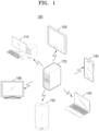
- FIG. 1 illustrates a game providing system 100 including a server and a user terminal, according to various embodiments.
- the game providing system 100 of the present disclosure may include a server 170 and at least one user terminals 110 to 160.
- the server 170 may provide various online activities through a network.
- the server 170 may simultaneously provide online activities to the at least one user terminal 110 to 160.
- the server 170 may include a single server, a set of servers, a cloud server, or the like, and is not limited thereto.
- the server 170 may provide various online activities, and may include a database for storing data for online activities.
- the server 170 may include a payment server that generates and processes payment events.
- the server 170 may be a game providing apparatus.
- a network may mean a connection established (or formed) by using all communication methods, and may mean a communication network connected through all communication methods, the communication network being configured to transmit and receive data between a terminal and a terminal or between a terminal and a server.
- All communication methods may include all communication methods such as communication through a certain communication standard, a certain frequency band, a certain protocol, or a certain channel.
- all communication methods may include communication methods through Bluetooth, Bluetooth Low Energy (BLE), Zigbee, Third Generation (3G), long-term evolution (LTE), ultrasound, or the like, and may include all of the short-distance communication, long-distance communication, wireless communication, and wired communication.
- BLE Bluetooth Low Energy
- 3G Third Generation
- LTE long-term evolution
- ultrasound or the like, and may include all of the short-distance communication, long-distance communication, wireless communication, and wired communication.
- the present disclosure is not limited thereto.
- the short-range communication method may mean a communication method in which communication is possible only when a device (terminal or server) performing communication is within a certain range, and may include, for example, Bluetooth, Near Field Communication (NFC), or the like.
- the long-distance communication method may mean a communication method in which a device performing communication may communicate regardless of a distance.
- the long-distance communication method may mean a method in which two devices performing communication through a repeater such as an access point (AP) may communicate even when a distance therebetween is greater than or equal to a certain distance, and may include a communication method using a cellular network (3G, LTE) such as short message service (SMS) or telephone.
- 3G, LTE cellular network
- SMS short message service
- the present disclosure is not limited thereto.
- the meaning of being provided with online activities by using a network may include the meaning that communication between a server and a terminal may be performed through all communication methods.
- the at least one user terminal 110 to 160 may include a personal computer 110, a tablet 120, a cellular phone 130, a notebook 140, a smartphone 150, a television (TV) 160, as well as various electronic devices such as a personal digital assistant (PDA), a portable multimedia player (PMP), a navigation device, an MP3 player, a digital camera, a refrigerator, a washing machine, a vacuum cleaner, or the like, and are not limited thereto.
- PDA personal digital assistant
- PMP portable multimedia player
- the at least one user terminal 110 to 160 may each be a game providing device.
- the at least one user terminal 110 to 160 may each display a user interface for obtaining an input of direction through a touch screen.
- the at least one user terminal 110 to 160 may each obtain, through the user interface, a user's touch input of dragging from a reference point where a touch is started to a current touch point.
- the at least one user terminal 110 to 160 may each display an input direction indicator indicating an input direction from the reference point toward the current touch point at a position farther away from the reference point than the current touch point on the user interface, in response to the user's input.
- the at least one user terminal 110 to 160 may individually perform a method of providing a touch screen interface according to various embodiments of the present disclosure. However, the present disclosure is not limited thereto.
- the at least one user terminal 110 to 160 may each display a user interface for obtaining an input of direction through a touch screen under the control by the server 170 through communication with the server 170.
- FIG. 2 is a flowchart illustrating method 200 of providing a touch screen interface, according to various embodiments. Such method 200 may be performed by the at least one user terminal 110 to 160 of FIG. 1 , a game providing apparatus 1000 shown in FIG. 10 , or a processor 1010 of the game providing apparatus 1000.
- a user terminal may display a user interface for obtaining an input of direction through a touch screen.
- the user interface may be a graphical user interface (GUI) for obtaining a user's direction input operation in a user terminal having a touch screen.
- GUI graphical user interface
- the user interface may be an interface for moving an object to be operated.
- the object to be operated may be any graphic element that may be moved by a user's operation.
- the object to be operated may be a player character (PC) or thing that a user may control in a virtual space.
- PC player character
- the present disclosure is not limited thereto.
- the user interface for obtaining an input of direction may be displayed when a movement operation is required.
- the user interface may be displayed only in a situation where the object to be operated may be operated, otherwise, the user interface may be removed from a screen.
- the user interface for obtaining an input of direction may be displayed overlaid on other screen elements displayed on the touch screen.
- the user interface may be translucently displayed so that other screen elements are not covered.
- the transparency of each of elements in the user interface may be different from each other.
- the user terminal may obtain a user's touch input of dragging from a reference point where a touch is started to a current touch point through the user interface.
- the user terminal may determine a direction from the reference point where a touch is started toward the current touch point as an input direction.
- the user may change the input direction while maintaining the input of direction by continuously dragging without releasing his/her hand after the touch.
- the user terminal may display an input direction indicator indicating the input direction from the reference point toward the current touch point at a position farther away from the reference point than the current touch point on the user interface, in response to the user's touch input.
- a direction indicated by the input direction indicator may be dynamically changed as the current touch point is changed while the user's touch input is continued.
- the size of the input direction indicator may increase as a distance between the reference point and the current touch point increases. In an embodiment, a distance between the reference point and the input direction indicator may increase in proportion to the distance between the reference point and the current touch point. In an embodiment, the sharpness of the input direction indicator may increase as the distance between the reference point and the current touch point increases. In an embodiment, the shape of the input direction indicator may be determined according to the distance between the reference point and the current touch point. In an embodiment, the size, distance, sharpness, or shape of the input direction indicator may be dynamically changed as the current touch point is changed while the user's touch input is continued. This will be described in more detail with reference to FIG. 8 .
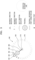
- FIG. 3 is a diagram for explaining a configuration of a touch screen interface according to various embodiments.
- FIG. 3 illustrates an example of a direction input interface 300 displayed in a user terminal having a touch screen.
- the direction input interface 300 may be a GUI for obtaining a direction input operation of a user in a user terminal having a touch screen.
- the direction input interface 300 may be an interface for moving an object to be operated.
- the object to be operated may be any graphic element that may be moved by a user's operation.
- the object to be operated may be a PC or thing that a user may control in a virtual space.
- a user may input a direction by touching and then dragging on the direction input interface 300.
- the user terminal may determine a direction from a point where a touch is started toward the current touch point as an input direction.
- the user may change the input direction while maintaining the input of direction by continuously dragging without releasing his/her hand after the touch.
- the direction input interface 300 may include a reference point 310, a trackball 320, an input direction indicator 330, a movement direction indicator 340, a first movement direction identifier 350, a second movement direction identifier 355, a trackball-reference point connection line 360, and an operation boundary line 370.
- the direction input interface 300 is not limited to an example of FIG. 3 , and more components than those shown in FIG. 3 may be included in the direction input interface 300 or fewer components than those shown in FIG. 3 may be included in the direction input interface 300.
- the movement direction indicator 340 may not be included in the direction input interface 300.
- the components shown in FIG. 3 may not be illustrated or may be omitted under certain conditions.
- the reference point 310 may be an interface indicating a reference position of an input of direction.
- the reference point 310 may be displayed at a point where the user starts the touch.
- the reference point 310 may be displayed at a default position. In another embodiment, when there is no input of direction by the user, the reference point 310 may not be displayed.
- the trackball 320 may be an interface indicating a point currently being touched by the user.
- a position of the trackball 320 may be changed to a current touch point in real time while the user continues the drag input.
- the trackball 320 may be displayed at a default position. In another embodiment, when there is no input of direction by the user, the trackball 320 may not be displayed.
- the input direction indicator 330 may be an interface indicating a current input direction, that is, a direction from a reference point 310 toward a current touch point.
- the input direction indicator 330 may be displayed as an arrow indicating an input direction.
- the input direction indicator 330 may be displayed when a user's drag input is sensed.
- a direction indicated by the input direction indicator 330 may be dynamically changed as the current touch point is changed while the user's touch input is continued.
- the input direction indicator 330 is displayed at a position farther away from a reference point 310 than a current touch point. In other words, a distance between the reference point 310 and the input direction indicator 330 may be greater than a distance between the reference point 310 and the current touch point.
- the input direction indicator 330 is displayed outside the operation boundary line 370.
- the movement direction indicator 340 may be an interface indicating a movement direction of an object to be operated, the movement direction being determined according to a current input direction.
- the movement direction indicator 340 may be displayed as an arrow indicating a movement direction.
- the object to be operated may move in all directions, and the movement direction may be the same as the input direction. That is, the user terminal may move the object to be operated in the input direction.
- a direction in which the object to be operated may move may be preset, and the movement direction may be determined based on the input direction.
- the movement direction indicator 340 may be displayed when a user's drag input is sensed. In an embodiment, a direction indicated by the movement direction indicator 340 may be dynamically changed as the current touch point is changed while the user's touch input is continued.
- the movement direction indicator 340 may be displayed when directions in which the object to be operated may move and a range of an input direction corresponding to each of movable directions are preset.
- the movement direction indicator 340 may not be displayed when the object to be operated may move in all directions, but may be displayed only when the movement direction is limited, that is, when the input direction is different from the movement direction. In this case, directions indicated by the input direction indicator 330 and the movement direction indicator 340 may be different. This will be described in more detail with reference to FIGS. 5 to 7 .
- the movement direction indicator 340 may always be displayed regardless of the setting of the movement direction. In other words, the movement direction indicator 340 may be displayed both when the object to be operated may move in all directions and when the movement direction is limited.
- the movement direction indicator 340 may be displayed at a position farther away from the reference point 310 than the current touch point. In other words, a distance between the reference point 310 and the movement direction indicator 340 may be greater than a distance between the reference point 310 and the current touch point. For example, the movement direction indicator 340 may be displayed outside the operation boundary line 370.
- the first movement direction identifier 350 and the second movement direction identifier 355 may each be an interface indicating a range of an input direction corresponding to each of movable directions.
- the first movement direction identifier 350 and the second movement direction identifier 355 may include scales indicating boundaries in which the movement direction is changed according to the input direction.
- the first movement direction identifier 350 and the second movement direction identifier 355 may each be displayed when a user's drag input is sensed.
- the first movement direction identifier 350 and the second movement direction identifier 355 may be displayed.
- the first movement direction identifier 350 and the second movement direction identifier 355 may not be displayed when the object to be operated may move in all directions, but may be displayed only when a movement direction is limited, that is, when the input direction is different from the movement direction.
- the first movement direction identifier 350 may be displayed at a position farther away from the reference point 310 than the current touch point, and the second movement direction identifier 355 may be displayed around the reference point 310.
- the first movement direction identifier 350 may be displayed outside the operation boundary line 370.
- only one of the first movement direction identifier 350 and the second movement direction identifier 355 may be displayed.
- the sharpness of scales in the first movement direction identifier 350 and the second movement direction identifier 355 may decrease as the distance between the scales and the current input direction or the current movement direction increases.
- a scale in a direction closer to the current input direction or the current movement direction may be opaquely or clearly displayed, and a scale in a direction farther away from the current input direction or the current movement direction may be transparently or blurrily displayed.
- the sharpness of scales in the first movement direction identifier 350 and the second movement direction identifier 355 may be dynamically changed as the current touch point is changed while the user's touch input is continued.
- the trackball-reference point connection line 360 may be displayed as a straight line connecting the reference point 310 where a touch is started and the trackball 320 indicating a current touch position.
- the trackball-reference point connection line 360 may be a line indicating the current input direction.
- the trackball-reference point connection line 360 may be displayed when a user's drag input is sensed.
- the trackball-reference point connection line 360 may be dynamically changed as the current touch point is changed while the user's touch input is continued.
- the operation boundary line 370 is an interface indicating a maximum range of an input of direction that a user may perform.
- the operation boundary line 370 may indicate a range in which the trackball 320 may be positioned.
- the operation boundary line 370 may be a circle using the reference point 310 as a center.
- the operation boundary line 370 may be displayed when a user's drag input is sensed.
- the operation boundary line 370 may be a virtual area that is not displayed on a touch screen.
- a radius of the operation boundary line 370 may be greater than a distance between the reference point 310 and a current touch point. Accordingly, the operation boundary line 370 may be set to always include the trackball 320.
- the operation boundary line 370 may be a reference that determines positions of the input direction indicator 330, the movement direction indicator 340, and/or the first movement direction identifier 350.
- the input direction indicator 330, the movement direction indicator 340, and/or the first movement direction identifier 350 may be set to be positioned outside the operation boundary line 370.
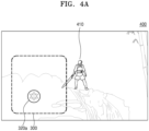
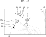
- FIGS. 4A and 4B are diagrams each explaining a method of displaying a touch screen interface, according to various embodiments.
- FIGS. 4A and 4B respectively show examples 400 and 450 of a game screen on which the direction input interface 300 is displayed in a user terminal.
- the direction input interface 300 may be displayed overlaid on the game screen.
- the direction input interface 300 may be a user interface for moving a game character 410 that may be operated by a user.
- the direction input interface 300 may be displayed when the game character 410 may be operated.
- FIGS. 4A and 4B respectively show examples 400 and 450 in which the direction input interface 300 is used in a game application, but it should be understood that the direction input interface 300 may be used to move an operable object in an application other than a game application.
- FIG. 4A illustrates example 400 of the direction input interface 300 when a user does not perform an input of direction.
- elements in the direction input interface 300 may not be displayed when there is no user's touch input or when a touch gesture other than an input of direction is sensed.
- the input direction indicator 330, the movement direction indicator 340, the first movement direction identifier 350, the second movement direction identifier 355, the trackball-reference point connection line 360, and the operation boundary line 370 may not be displayed.
- the reference point 310 and the trackball 320 may be displayed at a default position 320a.
- a user may start an input of direction by touching and dragging the trackball 320 displayed at the default position 320a.
- the trackball 320 displayed at the default position 320a is only displayed to indicate a position of the direction input interface 300, and the user may start an input of direction by touching and dragging from any position within an area of the direction input interface 300 as well as the default position 320a.
- the reference point 310 may be displayed by being changed to a position where a touch is started.
- FIG. 4B illustrates example 450 of the direction input interface 300 while a user is performing an input of direction.
- the reference point 310, a trackball 320b, the input direction indicator 330, the movement direction indicator 340, the first movement direction identifier 350, the second movement direction identifier 355, and the trackball-reference point connection line 360 may be displayed based on the reference point 310 and a current touch position.
- the user terminal may determine a movement direction of the game character 410, which is an object to be operated, based on a user's touch input through the direction input interface 300.
- the user terminal may move the game character 410 in a determined movement direction.
- an input direction, a movement direction, and/or a boundary in which the movement direction is changed may be displayed at a position not covered by a touch input subject. Accordingly, the user may clearly and intuitively check a current input state and a movement state performed as a result of an input, thereby increasing the convenience of operation.
- FIG. 5 is a flowchart illustrating method 500 of providing a touch screen interface, according to various embodiments. Such method 500 may be performed by the at least one user terminal 110 to 160 of FIG. 1 , the game providing apparatus 1000 shown in FIG. 10 , or the processor 1010 of the game providing apparatus 1000.
- a user terminal may display a user interface for obtaining an input of direction through a touch screen.
- the user terminal may obtain a user's touch input of dragging from a reference point where a touch is started to a current touch point through the user interface.
- the user terminal may display an input direction indicator indicating an input direction from the reference point toward the current touch point at a position farther away from the reference point than the current touch point on the user interface, in response to the touch input of the user.
- Operations S510 to S530 may respectively correspond to operations S210 to S230 of FIG. 2 , and thus redundant descriptions thereof are omitted.
- the user terminal may determine a movement direction corresponding to the input direction from among preset movable directions.
- the user terminal may determine a direction corresponding to a current input direction from among the movable directions as a movement direction.
- directions in which the object to be operated may move may be set to be eight directions, and eight input direction ranges may correspond to the movable directions, respectively.
- Eight movable directions may be set as up, down, left, right, upper left, lower left, upper right, and lower right directions.
- directions in which the object to be operated may move may be set to be sixteen directions, and sixteen input direction ranges may respectively correspond to the movable directions.
- directions in which the object to be operated may move may be set to be thirty-two directions, and thirty-two input direction ranges may respectively correspond to the movable directions.
- the present disclosure is not limited thereto.
- the object to be operated may move in all directions, and the user terminal may determine the input direction as a movement direction.
- the movable directions of the object to be operated may be set by the user.
- the user may select one of cases of eight directions, sixteen directions, thirty two directions, and unlimited directions as the movable directions of the object to be operated.
- the present disclosure is not limited thereto.
- the user terminal may determine the movement direction on the basis of the movable directions selected by the user.
- the user terminal may determine a moving speed of the object to be operated on the basis of a user input through the user interface.
- the user terminal may determine the moving speed according to a distance from a point where a touch is started to a current touch point. For example, when the distance from the reference point to the current touch point is less than or equal to a certain reference distance, the moving speed may be determined as a first speed, and when the distance from the reference point to the current touch point is greater than the reference distance, the moving speed may be determined as a second speed which is faster than the first speed.
- the present disclosure is not limited thereto, and the moving speed may also be determined according a plurality of reference distances instead of one reference distance.
- the user terminal may display a movement direction indicator indicating the determined movement direction at a position farther away from the reference point than the current touch point on the user interface, in response to the user's touch input
- a direction indicated by the movement direction indicator may be dynamically changed as the current touch point is changed while the user's touch input is continued.
- the user terminal may further display a movement direction identifier indicating a range of an input direction corresponding to each of the movable directions on the user interface, in response to the user's touch input.
- the movement direction identifier may be displayed at at least one of a position farther away from the reference point than the current touch point and a position around the reference point.
- the movement direction indicator and the movement direction identifier may be displayed when directions in which the object to be operated may move and a range of an input direction corresponding to each of the movable directions are preset.
- the movement direction indicator and the movement direction identifier may not be displayed when the object to be operated may move in all directions, but may be displayed only when the movement direction is limited, that is, when the input direction is different from the movement direction. In this case, directions indicated by the input direction indicator and the movement direction indicator may be different.
- the movement direction indicator may always be displayed regardless of the setting of the movement direction. In other words, the movement direction indicator may be displayed both when the object to be operated may move in all directions and when the movement direction is limited.
- the size of the movement direction indicator or the movement direction identifier may increase as the distance between the reference point and the current touch point increases. In an embodiment, the distance between the reference point and the movement direction indicator or the movement direction identifier may increase in proportion to the distance between the reference point and the current touch point. In an embodiment, the sharpness of the movement direction indicator or the movement direction identifier may increase as the distance between the reference point and the current touch point increases. In an embodiment, the shape of the movement direction indicator may be determined according to the distance between the reference point and the current touch point. In an embodiment, the size, distance, sharpness, or shape of the movement direction indicator or the movement direction identifier may be dynamically changed as the current touch point is changed while the user's touch input is continued. This will be described in more detail with reference to FIG. 8 .
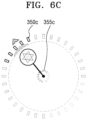
- FIGS. 6A, 6B , and 6C are diagrams each explaining a configuration of a touch screen interface, according to various embodiments.
- FIGS. 6A, 6B , and 6C show an example of a direction input interface displayed in a user terminal when movable directions are set to eight directions, sixteen directions, and thirty-two directions, respectively.
- First movement direction identifiers 350a, 350b, and 350c and second movement direction identifiers 355a, 355b, and 355c in the direction input interface may indicate eight, sixteen, and thirty-two input direction ranges corresponding to eight, sixteen, and thirty-two movable directions, respectively.
- scales in the first movement direction identifiers 350a, 350b, and 350c and the second movement direction identifiers 355a, 355b, and 355c may indicate boundaries of each of input direction ranges.
- the input direction ranges corresponding to movable directions may be set equally. For example, when there are n movable directions, the input direction ranges may be a range obtained by dividing 360 degrees by n. In another embodiment, the input direction ranges corresponding to the movable directions may be set differently. For example, an input direction range corresponding to a left-right direction may be set to be greater than an input direction range corresponding to an up-down direction, or vice versa. Accordingly, the operation sensitivity in a particular direction may be set greater or less.
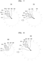
- FIG. 7 is a diagram for explaining an operation of a touch screen interface, according to various embodiments.
- the direction input interface may include the reference point 310, the trackball 320, the input direction indicator 330, the movement direction indicator 340, a movement direction identifier 350, the trackball-reference point connection line 360, and the operation boundary line 370.
- the components of the direction input interface may respectively correspond to the reference point 310, the trackball 320, the input direction indicator 330, the movement direction indicator 340, the first movement direction identifier 350, the trackball-reference point connection line 360, and the operation boundary line 370, and thus redundant descriptions thereof are omitted.
- the user terminal may display the movement direction identifier 350 indicating ranges of input directions corresponding to preset movable directions, according to a user's touch input.
- the movement direction identifier 350 may include scales 350-1, 350-2, 350-3 indicating boundaries of the input direction ranges.
- the user terminal may determine a direction connecting a current touch point from the reference point 310 as an input direction.
- the user terminal may display the input direction indicator 330 indicating the determined input direction.
- the user terminal may determine a range in which the input direction is included from among the input direction ranges, and may determine a movable direction corresponding to the included range as a movement direction.
- the user terminal may display the movement direction indicator 340 indicating the determined movement direction.
- the input direction indicator 330 may be displayed to point to the first direction.
- the user terminal may identify that the first direction, which is the current input direction, is included in a first input direction range defined between a direction of the scale 350-1 and a direction of the scale 350-2, and determine a movable direction corresponding to the first input direction range as the movement direction.
- the movement direction indicator 340 may be displayed between the direction of the scale 350-1 and the direction of the scale 350-2 to indicate the movement direction.
- the position of the movement direction indicator 340 may not be changed.
- the input direction indicator 330 may be displayed to point to the second direction.
- the user terminal may identify that the second direction, which is the current input direction, is included in a second input direction range defined between the direction of the scale 350-1 and a direction of the scale 350-3, and determine a movable direction corresponding to the second input direction range as a changed movement direction.
- the position of the movement direction indicator 340 may be changed between the direction of the scale 350-1 and the direction of the scale 350-3 to indicate the changed movement direction. Accordingly, when the position of the input direction indicator 330 is continuously changed while passing the scales 350-1, 350-2, and 350-3 of the movement direction identifier 350, the position of the movement direction indicator 340 may be discontinuously changed.
- a user may easily identify a current input direction, a current movement direction, and an input direction required to change the movement direction through a movement direction indicators and a movement direction identifier.
- the user may clearly recognize that a movement direction is determined and changed as a result of an actual input. Therefore, a more delicate and accurate direction operation is possible.
- FIG. 8 is a diagram for explaining an operation of a touch screen interface, according to various embodiments.
- the direction input interface may include the reference point 310, the trackball 320, the input direction indicator 330, the movement direction indicator 340, the movement direction identifier 350, the trackball-reference point connection line 360, and the operation boundary line 370.
- the components of the direction input interface may respectively correspond to the reference point 310, the trackball 320, the input direction indicator 330, the movement direction indicator 340, the first movement direction identifier 350, the trackball-reference point connection line 360, and the operation boundary line 370, and thus redundant descriptions thereof are omitted.
- the size of at least some components in the direction input interface may increase as the distance between the reference point 310 and the current touch point increases. In various embodiments, the size of at least some components in the direction input interface may be dynamically changed as the current touch point is changed while the user's touch input is continued.
- the size of the input direction indicator 330 may increase as the distance between the reference point 310 and the current touch point increases.
- the input direction indicator 330 may be displayed smaller as the current touch point is closer to the reference point 310, and may be displayed larger as the current touch point is farther away from the reference point 310.
- the size of the movement direction indicator 340 may increase as the distance between the reference point 310 and the current touch point increases.
- the movement direction indicator 340 may be displayed smaller as the current touch point is closer to the reference point 310, and may be displayed larger as the current touch point is further away from the reference point 310.
- the size of the movement direction identifier 350 may increase as the distance between the reference point 310 and the current touch point increases. In other words, the movement direction identifier 350 may be displayed smaller as the current touch point is closer to the reference point 310, and may be displayed larger as the current touch point is further away from the reference point 310.
- a range of the operation boundary line 370 may be determined based on a distance between the reference point 310 and the current touch point. For example, as the distance between the reference point 310 and the current touch point increases, the range of the operation boundary line 370 may increase.
- a minimum size of the operation boundary line 370 may be preset. For example, the operation boundary line 370 at a minimum size may be displayed until a drag input of the user is started and the distance between the reference point 310 and the current touch point is less than a certain distance.
- a maximum size of the operation boundary line 370 may be preset. For example, when the current touch point is far away from the reference point 310 in a distance greater than or equal to a certain distance, the size of the operation boundary line 370 may be fixed to the maximum size, and even when the user's drag input continues outside the operation boundary line 370, the position of the trackball 320 may be inside the operation boundary line 370. In this case, the user terminal may consider that the current touch point is the position of the trackball 320 inside the operation boundary line 370.
- the operation boundary line 370 may be a reference that determines the positions of the input direction indicator 330, the movement direction indicator 340, and/or the movement direction identifier 350.
- the input direction indicator 330, the movement direction indicator 340, and/or the movement direction identifier 350 may be set to be positioned outside the operation boundary line 370.
- the operation boundary line 370 is expanded based on a distance between the reference point 310 and the current touch point, the input direction indicator 330, the movement direction indicator 340, and/or the movement direction identifier 350 may also be expanded together to be positioned outside the operation boundary line 370.
- a distance between at least some components in the direction input interface and the reference point 310 may increase as the distance between the reference point 310 and the current touch point increases. In various embodiments, a distance between at least some components in the direction input interface and the reference point 310 may be dynamically changed as the current touch point is changed while the user's touch input is continued.
- the distance between the reference point 310 and the input direction indicator 330 may increase in proportion to the distance between the reference point 310 and the current touch point.
- the input direction indicator 330 may also be displayed at a position farther away from the reference point 310.
- the input direction indicator 330 may also be expanded together to be displayed outside the operation boundary line 370.
- a distance between the reference point 310 and the movement direction indicator 340 may increase in proportion to a distance between the reference point 310 and the current touch point.
- the movement direction indicator 340 may also be displayed at a position farther away from the reference point 310.
- the movement direction indicator 340 may also be expanded together to be displayed outside the operation boundary line 370.
- a distance between the reference point 310 and the movement direction identifier 350 may increase in proportion to a distance between the reference point 310 and the current touch point.
- the movement direction identifier 350 may also be displayed at a position farther away from the reference point 310.
- the movement direction identifier 350 may also be expanded together to be displayed outside the operation boundary line 370.
- the sharpness of at least some components in the direction input interface may increase as the distance between the reference point 310 and the current touch point increases. In various embodiments, the sharpness of at least some components in the direction input interface may be dynamically changed as the current touch point is changed while the user's touch input is continued.
- the sharpness of the reference point 310 and the trackball-reference point connection line 360 may increase as the distance between the reference point 310 and the current touch point increases.
- the reference point 310 and the trackball-reference point connection line 360 may be transparently or blurrily displayed as the current touch point is closer to the reference point 310, and may be opaquely or clearly displayed as the current touch point is farther away from the reference point 310.
- the sharpness of the input direction indicator 330 may increase as the distance between the reference point 310 and the current touch point increases.
- the input direction indicator 330 may be transparently or blurrily displayed as the current touch point is closer to the reference point 310, and may be opaquely or clearly displayed as the current touch point is farther away from the reference point 310.
- the sharpness of the movement direction indicator 340 may increase as the distance between the reference point 310 and the current touch point increases.
- the movement direction indicator 340 may be transparently or blurrily displayed as the current touch point is closer to the reference point 310, and may be opaquely or clearly displayed as the current touch point is farther away from the reference point 310.
- the sharpness of the movement direction identifier 350 may increase as the distance between the reference point 310 and the current touch point increases.
- the movement direction identifier 350 may be transparently or blurrily displayed as the current touch point is closer to the reference point 310, and may be opaquely or clearly displayed as the current touch point is farther away from the reference point 310.
- a change in the size, distance, and/or sharpness of the movement direction identifier 350 may be equally applied to a first movement direction identifier displayed at a position farther from the reference point 310 than the current touch point and a second movement direction identifier displayed around the reference point 310.
- the change in size, distance, and/or sharpness of the movement direction identifier 350 may be applied only to the first movement direction identifier and not to the second movement direction identifier. That is, the size, distance, and/or sharpness of the second movement direction identifier may not change even when the current touch point is changed.
- the shape of at least some components in the direction input interface may be determined based on a distance between the reference point 310 and the current touch point. In various embodiments, the shape of at least some components in the direction input interface may be dynamically changed as the current touch point is changed while the user's touch input is continued.
- the shape of the input direction indicator 330 may be determined based on a distance between the reference point 310 and the current touch point. For example, when the distance between the reference point 310 and the current touch point is less than or equal to a certain reference distance, the input direction indicator 330 may be displayed in a first shape, and when the distance between the reference point 310 and the current touch point is greater than the reference distance, the input direction indicator 330 may be displayed in a second shape. As another example, the shape of the input direction indicator 330 may be continuously changed from the first shape to the second shape as the distance between the reference point 310 and the current touch point increases.
- the present disclosure is not limited thereto, and the shape of the input direction indicator 330 may also be determined according to a plurality of reference distances instead of one reference distance.
- the shape of the input direction indicator 330 may indicate the moving speed.
- the shape of the movement direction indicator 340 may be determined based on the distance between the reference point 310 and the current touch point. For example, when the distance between the reference point 310 and the current touch point is less than or equal to a certain reference distance, the movement direction indicator 340 may be displayed in a first shape, and when the distance between the reference point 310 and the current touch point is greater than the reference distance, the movement direction indicator 340 may be displayed in a second shape. As another example, the shape of the movement direction indicator 340 may be continuously changed from the first shape to the second shape as the distance between the reference point 310 and the current touch point increases.
- a visual effect may be additionally displayed on the movement direction indicator 340.
- the present disclosure is not limited thereto, and the shape of the movement direction indicator 340 may also be determined according to a plurality of reference distances instead of one reference distance.
- the shape of the movement direction indicator 340 may indicate the moving speed.
- an input direction, a movement direction, and/or a boundary at which the movement direction is changed may be displayed by dynamically changing the position and shape. That is, even when the user's touch point is changed, information about the input direction, the movement direction, and/or the boundary at which the movement direction is changed may be displayed at a position which is not covered by a touch input subject. Therefore, the user may clearly and intuitively check a current state of an input and a state of movement performed as a result of an input without stopping the input, regardless of a direction of operation.
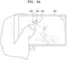
- FIGS. 9A and 9B are diagrams each illustrating an embodiment of using a touch screen interface of the present disclosure.
- FIG. 9A illustrates an example in which as user performs a touch input through a direction input interface according to various embodiments of the present disclosure in a user terminal 900 having a touch screen.
- a portion of the GUI is inevitably covered by the user's touch input subject.
- the reference point 310 which is a point where the touch input is started, or the trackball 320 indicating a current touch point may be covered by the user's hand while the touch input continues and may not be visible.
- the input direction indicator 330, the movement direction indicator 340, and the first movement direction identifier 350 may be displayed at a position farther away from the reference point 310 than the current touch point. Accordingly, the user may clearly recognize an input direction, a movement direction, and/or a boundary at which the movement direction is changed due to a current touch input without being disturbed by the touch input subject.
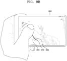
- FIG. 9B illustrates another example in which the user performs a touch input through a direction input interface according to various embodiments of the present disclosure in the user terminal 900 having the touch screen.
- the visibility of the input direction indicator 330, the movement direction indicator 340, and the first movement direction identifier 350 may decrease.
- the input direction indicator 330, the movement direction indicator 340, and the movement direction identifier 350 may be positioned at an edge of a screen or outside the screen, or may be covered by the user's hand.
- FIG. 10 is a diagram for explaining a detailed configuration of a game providing apparatus 1000 according to various embodiments.
- the game providing apparatus 1000 may include at least one processor 1010, a display 1030, a user input unit 1050, and a memory 1070. However, not all of the components shown in FIG. 10 are essential components of the game providing apparatus 1000.
- the game providing apparatus 1000 may be implemented by more components than those shown in FIG. 10 , or the game providing apparatus 1000 may be implemented by fewer components than those shown in FIG. 10 .
- the game providing apparatus 1000 may be a user terminal, a server, a game network system, or a separate apparatus.
- the processor 1010 controls all operations of the game providing apparatus 1000.
- the processor 1010 may generally control the display 1030, the user input unit 1050, the memory 1070, or the like by executing a program stored in the memory 1070.
- the processor 1010 may control an operation of the game providing apparatus 1000 in the present disclosure by controlling the display 1030, the user input unit 1050, the memory 1070, or the like.
- the processor 1010 may be configured to control a touch screen to display a user interface for obtaining an input of direction through the touch screen, obtain a user's touch input of dragging from a reference point where a touch is started to a current touch point through the user interface, and control the touch screen to display an input direction indicator indicating an input direction from the reference point toward the current touch point at a position farther away from the reference point than the current touch point on the user interface in response to the user's touch input.
- the size of the input direction indicator may be set to increase as the distance between the reference point and the current touch point increases.
- the size of the input direction indicator may be set to be dynamically changed as the current touch point is changed while the user's touch input is continued.
- the user interface may be configured to be displayed overlaid on other screen elements displayed on the touch screen, and the sharpness of the input direction indicator may be set to increase as the distance between the reference point and the current touch point increases.
- the processor 1010 may be further configured to determine a movement direction corresponding to the input direction from among preset movable directions, and control the touch screen to display a movement direction indicator indicating the determined movement direction at a position farther away from the reference point than the current touch point on the user interface in response to the user's touch input.
- the size of the movement direction indicator may be set to increase as the distance between the reference point and the current touch point increases, and the size of the movement direction indicator may be set to be dynamically changed as the current touch point is changed while the user's touch input is continued.
- the preset movable directions may be set to have eight directions, sixteen directions, thirty-two directions, or unlimited directions.
- the processor 1010 may be further configured to control the touch screen to display a movement direction identifier indicating a range of an input direction corresponding to each of the preset movable directions on the user interface in response to the user's touch input.
- the movement direction identifier may be configured to be displayed at at least one of a position farther away from the reference point than the current touch point and a position around the reference point.
- the size of the movement direction identifier may be set to increase as the distance between the reference point and the current touch point increases, and the size of the movement direction identifier may be set to be dynamically changed as the current touch point is changed while the user's touch input is continued.
- the processor 1010 may be further configured to move an object to be operated in the movement direction.
- the moving speed of the object to be operated may be set to be determined based on the distance between the reference point and the current touch point.
- the processor 1010 may be further configured to control the touch screen to display a connection line connecting the reference point and the current touch point on the user interface in response to the user's touch input.
- the user interface may be configured to be displayed overlaid on other screen elements displayed on the touch screen, and the sharpness of the connection line may be set to increase as the distance between the reference point and the current touch point increases.
- the display 1030 may display and output information processed by the game providing apparatus 1000.
- the display 1030 may include at least one of a liquid crystal display, a thin film transistor-liquid crystal display, an organic light-emitting diode, a flexible display, a three-dimensional (3D) display, and an electrophoretic display.
- the display 1030 and a touchpad form a layered structure to form a touch screen
- the display 1030 may be used as an input device in addition to an output device.
- the display 1030 may include a light emitting diode (LED) lamp, a vibration motor, a speaker, a flash, or the like, but is not limited thereto.
- LED light emitting diode
- the display 1030 may be a display forming a touch screen by being coupled to the user input unit 1050.
- the display 1030 may output a screen including a user interface according to various embodiments of the present disclosure under the control by the processor 1010.
- the user input unit 1050 means a unit for a user to input data for controlling the game providing apparatus 1000.
- the user input unit 1050 may include devices capable of receiving various types of user inputs, such as a keyboard, a physical button, a mouse, a joystick, a touch screen, a touch pad, a camera, or a microphone.
- the user input unit 1050 may include various interfaces such as a keypad, a dome switch, a voice input interface, a fingerprint input interface, a touch input interface (a contact capacitance method, a pressure resistance film method, an infrared sensing method, a surface ultrasonic conduction method, an integral tension measurement method, a piezo effect method, or the like), a camera, a jog wheel, and a jog switch, and may also line various sensors, such as an acceleration sensor, a position sensor, a temperature sensor, and an optical sensor, with the user interface.
- the user input unit 1050 may include a device supporting various inputs.
- the user input unit 1050 may be a touch input interface forming a touch screen by being coupled to the display 1030. According to various embodiments of the present disclosure, the user input unit 1050 may obtain a user's touch input for inputting a direction.
- the memory 1070 may store a program for processing and controlling the processor 1010, and may also store data input to the game providing apparatus 1000 or output from the game providing apparatus 1000.
- the processor 1010 may execute a method of controlling a touch screen device by using the program stored in the memory 1070.
- the memory 1070 may include at least one type of storage medium from among a flash memory type, a hard disk type, a multimedia card micro type, a card type memory (e.g., secure digital (SD) or extreme digital (XD) memory, or the like), random access memory (RAM), static RAM (SRAM), read-only memory (ROM), electrically erasable programmable ROM (EEPROM), programmable ROM (PROM), a magnetic memory, a magnetic disk, and an optical disk.
- programs stored in the memory 1070 may be classified into a plurality of modules according to functions thereof.
- a method of controlling a touch screen device may be performed by the game providing apparatus 1000, a server, or a user terminal, and in addition, at least one configuration in the game providing apparatus 1000 may perform embodiments described above with reference to FIGS. 1 to 9 .
- the method of controlling a touch screen device may be performed individually or together by the server and the user terminal.
- the apparatus described above may be implemented as a hardware component, a software component, and/or a combination of the hardware component and the software component.
- devices and components described in the embodiments may be implemented using one or more general-purpose computers or special-purpose computers, such as a processor, a controller, an arithmetic logic unit (ALU), a digital signal processor, a microcomputer, a programmable gate array (FPGA), a programmable logic unit (PLU), a microprocessor, or any other device capable of executing and responding to instructions.
- a processing device may execute an operating system (OS) and one or more software applications executed on the OS.
- the processing device may also access, store, operate, process, and generate data in response to execution of software.
- OS operating system
- the processing device may also access, store, operate, process, and generate data in response to execution of software.
- the processing device includes a plurality of processing elements and/or a plurality of types of processing elements.
- the processing device may include a plurality of processors or one processor and one controller.
- other processing configurations are also possible, such as parallel processors.
- Software may include a computer program, code, instructions, or a combination of one or more thereof, and may configure the processing device to operate as desired or, independently or collectively, instruct the processing device.
- Software and/or data may be permanently or temporarily embodied in any type of machine, component, physical device, virtual equipment, computer storage medium or device, or transmitted signal wave to be interpreted by a processing device or to provide instructions or data to the processing device.
- Software may be distributed over networked computer systems and stored or executed in a distributed manner.
- Software and data may be stored in one or more computer-readable recording media.
- the method according to the embodiment may be implemented in the form of program instructions that may be executed through various computer units and recorded in a computer-readable recording medium.
- the computer-readable recording medium may include program instructions, data files, data structures, or the like, alone or in combination.
- the program instructions recorded on the medium may be specially designed and configured for the embodiment, or may be known and available to those skilled in the art of computer software.
- Examples of the computer-readable recording medium include hardware devices specially configured to store and execute program instructions such as a magnetic medium such as a hard disk, an optical medium such as a CD-ROM and a DVD, a magneto-optical medium such as a floptical disk, ROM, RAM, flash memory, or the like.
- Examples of program instructions include not only machine language code such as those generated by a compiler, but also high-level language code that may be executed by a computer using an interpreter or the like.
- the hardware devices described above may be configured to operate as one or more software modules to perform operations of the embodiments, and vice versa.
- a method of providing a GUI for inputting a direction through a touch screen may be provided.
- a method of allowing the user to clearly and intuitively recognizing an input state and a result of an input may be provided.
- a method of allowing a user to delicately and accurately perform a direction operation through a touch screen may be provided.
Landscapes
- Engineering & Computer Science (AREA)
- Multimedia (AREA)
- Human Computer Interaction (AREA)
- Physics & Mathematics (AREA)
- General Engineering & Computer Science (AREA)
- Theoretical Computer Science (AREA)
- Optics & Photonics (AREA)
- General Physics & Mathematics (AREA)
- User Interface Of Digital Computer (AREA)
- Position Input By Displaying (AREA)
Claims (15)
- Ein Verfahren zum Steuern eines Berührungsbildschirmgeräts, wobei das Verfahren Folgendes beinhaltet:Anzeigen einer Benutzerschnittstelle (300) zum Erhalten einer Eingabe einer Richtung durch einen Berührungsbildschirm;Erhalten einer Benutzer-Berührungseingabe des Ziehens von einem Bezugspunkt (310), an dem eine Berührung anfängt, zu einem aktuellen Berührungspunkt (320) durch die Benutzerschnittstelle (300); undAnzeigen eines Eingaberichtungsindikators (300) an einer Position, die von dem Bezugspunkt (310) weiter entfernt ist als der aktuelle Berührungspunkt (320), auf der Benutzerschnittstelle (300) als Reaktion auf die Benutzer-Berührungseingabe;dadurch gekennzeichnet, dass der Eingaberichtungsindikator (300) durch seine Position in Bezug auf den Bezugspunkt eine Eingaberichtung von dem Bezugspunkt (310) hin zu dem aktuellen Berührungspunkt (320) angibt; undder Eingaberichtungsindikator (330) außerhalb einer Region positioniert ist, die einen Maximalbereich einer Eingabe einer Richtung, die der Benutzer durchführen kann, angibt.
- Verfahren gemäß Anspruch 1, wobei eine Größe des Eingaberichtungsindikators (330) mit zunehmender Entfernung zwischen dem Bezugspunkt (310) und dem aktuellen Berührungspunkt (320) zunimmt.
- Verfahren gemäß Anspruch 2, wobei die Größe des Eingaberichtungsindikators (330) mit Änderung des aktuellen Berührungspunktes (320), während die Berührungseingabe des Benutzers fortgesetzt wird, dynamisch geändert wird.
- Verfahren gemäß Anspruch 1, wobei das Anzeigen der Benutzerschnittstelle (300) das Anzeigen der Benutzerschnittstelle (300), sodass sie andere Bildschirmelemente, die auf dem Berührungsbildschirm angezeigt werden, überlagert, beinhaltet und
eine Transparenz des Eingaberichtungsindikators (330) mit zunehmender Entfernung zwischen dem Bezugspunkt (310) und dem aktuellen Berührungspunkt (320) zunimmt. - Verfahren gemäß Anspruch 1, das ferner Folgendes beinhaltet:Bestimmen einer Bewegungsrichtung, die der Eingaberichtung entspricht, aus voreingestellten bewegbaren Richtungen; undAnzeigen eines Bewegungsrichtungsindikators, der die bestimmte Bewegungsrichtung angibt, an einer Position, die von dem Bezugspunkt (310) weiter entfernt ist als der aktuelle Berührungspunkt (320), auf der Benutzerschnittstelle (300) als Reaktion auf die Benutzer-Berührungseingabe.
- Verfahren gemäß Anspruch 5, wobei eine Größe des Bewegungsrichtungsindikators mit zunehmender Entfernung zwischen dem Bezugspunkt (310) und dem aktuellen Berührungspunkt (320) zunimmt und
die Größe des Bewegungsrichtungsindikators mit Änderung des aktuellen Berührungspunktes (320), während die Berührungseingabe des Benutzers fortgesetzt wird, dynamisch geändert wird. - Verfahren gemäß Anspruch 5, wobei die voreingestellten Bewegungsrichtungen als einer von Fällen von acht Richtungen, sechzehn Richtungen oder zweiunddreißig Richtungen eingestellt sind.
- Verfahren gemäß Anspruch 5, das ferner das Anzeigen eines Bewegungsrichtungsidentifikators, der einen Bereich einer Eingaberichtung entsprechend jeder der voreingestellten Bewegungsrichtungen angibt, auf der Benutzerschnittstelle (300) als Reaktion auf die Benutzer-Berührungseingabe beinhaltet.
- Verfahren gemäß Anspruch 8, wobei das Anzeigen des Bewegungsrichtungsidentifikators das Anzeigen des Bewegungsrichtungsidentifikators an mindestens einer von einer Position, die weiter von dem Bezugspunkt (310) entfernt ist als der aktuelle Berührungspunkt (320), und einer Position um den Bezugspunkt herum beinhaltet.
- Verfahren gemäß Anspruch 8, wobei eine Größe des Bewegungsrichtungsidentifikators mit zunehmender Entfernung zwischen dem Bezugspunkt (310) und dem aktuellen Berührungspunkt (320) zunimmt und
die Größe des Bewegungsrichtungsidentifikators mit Änderung des aktuellen Berührungspunktes (320), während die Berührungseingabe des Benutzers fortgesetzt wird, dynamisch geändert wird. - Verfahren gemäß Anspruch 5, das ferner das Bewegen eines zu betätigenden Objekts in der Bewegungsrichtung beinhaltet.
- Verfahren gemäß Anspruch 11, wobei eine Bewegungsgeschwindigkeit des zu betätigenden Objekts auf der Basis einer Entfernung zwischen dem Bezugspunkt (310) und dem aktuellen Berührungspunkt bestimmt wird.
- Verfahren gemäß Anspruch 1, das ferner das Anzeigen einer Verbindungslinie, die den Bezugspunkt (310) und den aktuellen Berührungspunkt (320) verbindet, auf der Benutzerschnittstelle (300) als Reaktion auf die Benutzer-Berührungseingabe beinhaltet.
- Verfahren gemäß Anspruch 13, wobei das Anzeigen der Benutzerschnittstelle (300) das Anzeigen der Benutzerschnittstelle (300), sodass sie andere Bildschirmelemente, die auf dem Berührungsbildschirm angezeigt werden, überlagert, beinhaltet und eine Transparenz der Verbindungslinie mit zunehmender Entfernung zwischen dem Bezugspunkt (310) und dem aktuellen Berührungspunkt (320) zunimmt.
- Eine Spielbereitstellungsvorrichtung (1000), die Folgendes beinhaltet:einen Berührungsbildschirm;einen Speicher (1070), der Anweisungen speichert; undmindestens einen Prozessor (1010), der betriebsfähig mit dem Berührungsbildschirm und dem Speicher gekoppelt ist und zur Ausführung der Anweisungen konfiguriert ist, wobei der mindestens eine Prozessor (1010) konfiguriert ist, um die Anweisungen für Folgendes auszuführen:Steuern des Berührungsbildschirms zum Anzeigen einer Benutzerschnittstelle (300) zum Erhalten einer Eingabe einer Richtung durch den Berührungsbildschirm;Erhalten einer Benutzer-Berührungseingabe des Ziehens von einem Bezugspunkt (310), an dem eine Berührung anfängt, zu einem aktuellen Berührungspunkt (320) durch die Benutzerschnittstelle (300); undSteuern des Berührungsbildschirms zum Anzeigen eines Eingaberichtungsindikators (330) an einer Position, die von dem Bezugspunkt (310) weiter entfernt ist als der aktuelle Berührungspunkt (320), auf der Benutzerschnittstelle (300) als Reaktion auf die Benutzer-Berührungseingabe;dadurch gekennzeichnet, dass der Eingaberichtungsindikator (300) durch seine Position in Bezug auf den Bezugspunkt eine Eingaberichtung von dem Bezugspunkt (310) hin zu dem aktuellen Berührungspunkt (320) angibt; undder Eingaberichtungsindikator (330) außerhalb einer Region positioniert ist, die einen Maximalbereich einer Eingaberichtung, die der Benutzer durchführen kann, angibt.
Applications Claiming Priority (2)
| Application Number | Priority Date | Filing Date | Title |
|---|---|---|---|
| KR20210023696 | 2021-02-22 | ||
| KR1020210050013A KR102595353B1 (ko) | 2021-02-22 | 2021-04-16 | 터치 스크린 인터페이스를 제공하는 방법 및 장치 |
Publications (3)
| Publication Number | Publication Date |
|---|---|
| EP4046700A1 EP4046700A1 (de) | 2022-08-24 |
| EP4046700C0 EP4046700C0 (de) | 2024-11-20 |
| EP4046700B1 true EP4046700B1 (de) | 2024-11-20 |
Family
ID=80628536
Family Applications (1)
| Application Number | Title | Priority Date | Filing Date |
|---|---|---|---|
| EP22157680.4A Active EP4046700B1 (de) | 2021-02-22 | 2022-02-21 | Verfahren und vorrichtung zur bereitstellung einer berührungsbildschirmschnittstelle |
Country Status (7)
| Country | Link |
|---|---|
| US (1) | US20220266138A1 (de) |
| EP (1) | EP4046700B1 (de) |
| JP (2) | JP7615071B2 (de) |
| CN (1) | CN114949849A (de) |
| ES (1) | ES2997611T3 (de) |
| PL (1) | PL4046700T3 (de) |
| TW (1) | TWI836354B (de) |
Families Citing this family (1)
| Publication number | Priority date | Publication date | Assignee | Title |
|---|---|---|---|---|
| JP7770636B2 (ja) * | 2023-07-31 | 2025-11-17 | 株式会社カプコン | プログラム、情報処理装置及びシステム |
Family Cites Families (16)
| Publication number | Priority date | Publication date | Assignee | Title |
|---|---|---|---|---|
| JP2009245239A (ja) * | 2008-03-31 | 2009-10-22 | Sony Corp | ポインタ表示装置、ポインタ表示検出方法、ポインタ表示検出プログラム及び情報機器 |
| WO2012074054A1 (ja) * | 2010-12-03 | 2012-06-07 | 南開工業株式会社 | 活性炭粉末とその製造方法、及び電気二重層キャパシタ |
| KR20130037826A (ko) * | 2011-10-07 | 2013-04-17 | (주)네오위즈게임즈 | 야구 게임의 타격 방법 및 시스템 |
| US20140040833A1 (en) * | 2012-03-01 | 2014-02-06 | Adobe Systems Incorporated | Edge-aware pointer |
| JP5563633B2 (ja) * | 2012-08-31 | 2014-07-30 | 株式会社スクウェア・エニックス | ビデオゲーム処理装置、およびビデオゲーム処理プログラム |
| US8641526B1 (en) * | 2012-10-05 | 2014-02-04 | Warmaging.net LLP | Using input from a mouse device to control a video game vehicle |
| JP6137453B2 (ja) * | 2013-02-08 | 2017-05-31 | インターナショナル・ビジネス・マシーンズ・コーポレーションInternational Business Machines Corporation | 制御装置及び制御プログラム |
| TWI502481B (zh) * | 2014-03-05 | 2015-10-01 | Acer Inc | 電子裝置以及使用者介面控制方法 |
| JP5843908B2 (ja) * | 2014-03-07 | 2016-01-13 | 株式会社コナミデジタルエンタテインメント | ゲーム制御装置、ゲームシステム、及びプログラム |
| US9561432B2 (en) * | 2014-03-12 | 2017-02-07 | Wargaming.Net Limited | Touch control with dynamic zones |
| JP5830806B1 (ja) * | 2015-04-13 | 2015-12-09 | 株式会社Cygames | ユーザ入力の操作性を向上させるプログラム、電子装置、及び方法 |
| WO2017018384A1 (ja) * | 2015-07-28 | 2017-02-02 | 日本電信電話株式会社 | タッチパネル型情報端末装置とその情報入力処理方法およびプログラム |
| KR101922894B1 (ko) | 2016-04-11 | 2018-11-28 | 주식회사 네오위즈 | 음악 게임 장치, 방법 및 이를 위한 프로그램을 기록한 컴퓨터로 읽을 수 있는 기록매체 |
| JP6948124B2 (ja) * | 2016-12-14 | 2021-10-13 | エヌエイチエヌ コーポレーション | プログラムおよび画像制御方法 |
| JP6450794B2 (ja) | 2017-03-27 | 2019-01-09 | 株式会社コナミデジタルエンタテインメント | ゲームシステム、ゲーム制御装置、及びプログラム |
| CN107899235B (zh) * | 2017-10-13 | 2019-05-17 | 网易(杭州)网络有限公司 | 信息处理方法及装置、存储介质、电子设备 |
-
2022
- 2022-02-18 US US17/675,655 patent/US20220266138A1/en active Pending
- 2022-02-21 PL PL22157680.4T patent/PL4046700T3/pl unknown
- 2022-02-21 ES ES22157680T patent/ES2997611T3/es active Active
- 2022-02-21 EP EP22157680.4A patent/EP4046700B1/de active Active
- 2022-02-22 TW TW111106404A patent/TWI836354B/zh active
- 2022-02-22 CN CN202210162758.XA patent/CN114949849A/zh active Pending
- 2022-02-22 JP JP2022025287A patent/JP7615071B2/ja active Active
-
2023
- 2023-11-13 JP JP2023193206A patent/JP2024010249A/ja active Pending
Also Published As
| Publication number | Publication date |
|---|---|
| EP4046700C0 (de) | 2024-11-20 |
| TW202238357A (zh) | 2022-10-01 |
| TWI836354B (zh) | 2024-03-21 |
| US20220266138A1 (en) | 2022-08-25 |
| JP2022128447A (ja) | 2022-09-01 |
| JP7615071B2 (ja) | 2025-01-16 |
| CN114949849A (zh) | 2022-08-30 |
| EP4046700A1 (de) | 2022-08-24 |
| JP2024010249A (ja) | 2024-01-23 |
| ES2997611T3 (en) | 2025-02-17 |
| PL4046700T3 (pl) | 2025-03-17 |
Similar Documents
| Publication | Publication Date | Title |
|---|---|---|
| EP4239456B1 (de) | Verfahren und brillenartige tragbare-vorrichtung zur bereitstellung einer virtuellen eingabeschnittstelle | |
| ES2643176T3 (es) | Método y aparato para proporcionar informes de actividad independientes de la vista que responden a un gesto táctil | |
| US10649552B2 (en) | Input method and electronic device using pen input device | |
| US10775869B2 (en) | Mobile terminal including display and method of operating the same | |
| CN105808136A (zh) | 控制屏幕的方法和用于处理该方法的电子设备 | |
| CN108369479B (zh) | 在小形状因数显示器上的目标选择 | |
| US20120056819A1 (en) | Distance-time based hit-testing | |
| US20160306502A1 (en) | Standardizing user interface elements | |
| KR20160105694A (ko) | 전자 장치 및 전자 장치의 제어 방법 | |
| WO2018177207A1 (zh) | 操作控制方法、装置及存储介质 | |
| CN116964551A (zh) | 虚拟自动瞄准 | |
| KR20190131673A (ko) | 타겟 객체 선택 방법 및 이를 수행하기 위한 게이밍 디바이스 | |
| JP2022000787A (ja) | 画像制御方法およびプログラム | |
| KR102204599B1 (ko) | 화면 출력 방법 및 이를 수행하기 위한 디스플레이 장치 | |
| EP4046700B1 (de) | Verfahren und vorrichtung zur bereitstellung einer berührungsbildschirmschnittstelle | |
| CN105320260A (zh) | 移动终端的控制方法及移动终端 | |
| KR20180094323A (ko) | 인터랙션을 수행하는 방법 및 이를 사용하는 전자 장치 | |
| KR102595353B1 (ko) | 터치 스크린 인터페이스를 제공하는 방법 및 장치 | |
| EP3292461B1 (de) | Elektronische vorrichtung und betriebsverfahren dafür | |
| KR102137270B1 (ko) | 게임 알림 정보 제공 방법, 장치 및 시스템 | |
| KR102308927B1 (ko) | 화면 출력 방법 및 이를 수행하기 위한 디스플레이 장치 | |
| CN117157965A (zh) | 用于车辆的电子设备、用于控制用于车辆的电子设备的移动设备以及通过使用移动设备来控制用于车辆的电子设备的方法 | |
| KR102125100B1 (ko) | 웨어러블 디바이스의 제어 방법 및 그 장치 | |
| KR101992314B1 (ko) | 포인터 제어 방법 및 그 전자 장치 | |
| KR20160029525A (ko) | 사용자 인터페이스를 제어하는 방법 및 이를 제공하는 전자 장치 |
Legal Events
| Date | Code | Title | Description |
|---|---|---|---|
| PUAI | Public reference made under article 153(3) epc to a published international application that has entered the european phase |
Free format text: ORIGINAL CODE: 0009012 |
|
| STAA | Information on the status of an ep patent application or granted ep patent |
Free format text: STATUS: REQUEST FOR EXAMINATION WAS MADE |
|
| 17P | Request for examination filed |
Effective date: 20220221 |
|
| AK | Designated contracting states |
Kind code of ref document: A1 Designated state(s): AL AT BE BG CH CY CZ DE DK EE ES FI FR GB GR HR HU IE IS IT LI LT LU LV MC MK MT NL NO PL PT RO RS SE SI SK SM TR |
|
| RIC1 | Information provided on ipc code assigned before grant |
Ipc: A63F 13/537 20140101ALI20240328BHEP Ipc: A63F 13/533 20140101ALI20240328BHEP Ipc: A63F 13/2145 20140101ALI20240328BHEP Ipc: A63F 13/426 20140101AFI20240328BHEP |
|
| GRAP | Despatch of communication of intention to grant a patent |
Free format text: ORIGINAL CODE: EPIDOSNIGR1 |
|
| STAA | Information on the status of an ep patent application or granted ep patent |
Free format text: STATUS: GRANT OF PATENT IS INTENDED |
|
| INTG | Intention to grant announced |
Effective date: 20240617 |
|
| GRAS | Grant fee paid |
Free format text: ORIGINAL CODE: EPIDOSNIGR3 |
|
| GRAA | (expected) grant |
Free format text: ORIGINAL CODE: 0009210 |
|
| STAA | Information on the status of an ep patent application or granted ep patent |
Free format text: STATUS: THE PATENT HAS BEEN GRANTED |
|
| AK | Designated contracting states |
Kind code of ref document: B1 Designated state(s): AL AT BE BG CH CY CZ DE DK EE ES FI FR GB GR HR HU IE IS IT LI LT LU LV MC MK MT NL NO PL PT RO RS SE SI SK SM TR |
|
| REG | Reference to a national code |
Ref country code: GB Ref legal event code: FG4D |
|
| REG | Reference to a national code |
Ref country code: CH Ref legal event code: EP |
|
| REG | Reference to a national code |
Ref country code: DE Ref legal event code: R096 Ref document number: 602022007782 Country of ref document: DE |
|
| REG | Reference to a national code |
Ref country code: IE Ref legal event code: FG4D |
|
| U01 | Request for unitary effect filed |
Effective date: 20241209 |
|
| U07 | Unitary effect registered |
Designated state(s): AT BE BG DE DK EE FI FR IT LT LU LV MT NL PT RO SE SI Effective date: 20241219 |
|
| REG | Reference to a national code |
Ref country code: ES Ref legal event code: FG2A Ref document number: 2997611 Country of ref document: ES Kind code of ref document: T3 Effective date: 20250217 |
|
| U20 | Renewal fee for the european patent with unitary effect paid |
Year of fee payment: 4 Effective date: 20250226 |
|
| PG25 | Lapsed in a contracting state [announced via postgrant information from national office to epo] |
Ref country code: IS Free format text: LAPSE BECAUSE OF FAILURE TO SUBMIT A TRANSLATION OF THE DESCRIPTION OR TO PAY THE FEE WITHIN THE PRESCRIBED TIME-LIMIT Effective date: 20250320 Ref country code: HR Free format text: LAPSE BECAUSE OF FAILURE TO SUBMIT A TRANSLATION OF THE DESCRIPTION OR TO PAY THE FEE WITHIN THE PRESCRIBED TIME-LIMIT Effective date: 20241120 |
|
| PG25 | Lapsed in a contracting state [announced via postgrant information from national office to epo] |
Ref country code: NO Free format text: LAPSE BECAUSE OF FAILURE TO SUBMIT A TRANSLATION OF THE DESCRIPTION OR TO PAY THE FEE WITHIN THE PRESCRIBED TIME-LIMIT Effective date: 20250220 |
|
| PG25 | Lapsed in a contracting state [announced via postgrant information from national office to epo] |
Ref country code: GR Free format text: LAPSE BECAUSE OF FAILURE TO SUBMIT A TRANSLATION OF THE DESCRIPTION OR TO PAY THE FEE WITHIN THE PRESCRIBED TIME-LIMIT Effective date: 20250221 |
|
| PGFP | Annual fee paid to national office [announced via postgrant information from national office to epo] |
Ref country code: PL Payment date: 20250131 Year of fee payment: 4 |
|
| PG25 | Lapsed in a contracting state [announced via postgrant information from national office to epo] |
Ref country code: RS Free format text: LAPSE BECAUSE OF FAILURE TO SUBMIT A TRANSLATION OF THE DESCRIPTION OR TO PAY THE FEE WITHIN THE PRESCRIBED TIME-LIMIT Effective date: 20250220 |
|
| PG25 | Lapsed in a contracting state [announced via postgrant information from national office to epo] |
Ref country code: SM Free format text: LAPSE BECAUSE OF FAILURE TO SUBMIT A TRANSLATION OF THE DESCRIPTION OR TO PAY THE FEE WITHIN THE PRESCRIBED TIME-LIMIT Effective date: 20241120 |
|
| PG25 | Lapsed in a contracting state [announced via postgrant information from national office to epo] |
Ref country code: SK Free format text: LAPSE BECAUSE OF FAILURE TO SUBMIT A TRANSLATION OF THE DESCRIPTION OR TO PAY THE FEE WITHIN THE PRESCRIBED TIME-LIMIT Effective date: 20241120 |
|
| PG25 | Lapsed in a contracting state [announced via postgrant information from national office to epo] |
Ref country code: CZ Free format text: LAPSE BECAUSE OF FAILURE TO SUBMIT A TRANSLATION OF THE DESCRIPTION OR TO PAY THE FEE WITHIN THE PRESCRIBED TIME-LIMIT Effective date: 20241120 |
|
| PG25 | Lapsed in a contracting state [announced via postgrant information from national office to epo] |
Ref country code: MC Free format text: LAPSE BECAUSE OF FAILURE TO SUBMIT A TRANSLATION OF THE DESCRIPTION OR TO PAY THE FEE WITHIN THE PRESCRIBED TIME-LIMIT Effective date: 20241120 |
|
| PLBE | No opposition filed within time limit |
Free format text: ORIGINAL CODE: 0009261 |
|
| STAA | Information on the status of an ep patent application or granted ep patent |
Free format text: STATUS: NO OPPOSITION FILED WITHIN TIME LIMIT |
|
| REG | Reference to a national code |
Ref country code: CH Ref legal event code: PL |
|
| PG25 | Lapsed in a contracting state [announced via postgrant information from national office to epo] |
Ref country code: CH Free format text: LAPSE BECAUSE OF NON-PAYMENT OF DUE FEES Effective date: 20250228 |
|
| 26N | No opposition filed |
Effective date: 20250821 |
|
| PG25 | Lapsed in a contracting state [announced via postgrant information from national office to epo] |
Ref country code: IE Free format text: LAPSE BECAUSE OF NON-PAYMENT OF DUE FEES Effective date: 20250221 |
|
| U20 | Renewal fee for the european patent with unitary effect paid |
Year of fee payment: 5 Effective date: 20260226 |
|
| PGFP | Annual fee paid to national office [announced via postgrant information from national office to epo] |
Ref country code: GB Payment date: 20260225 Year of fee payment: 5 |
|
| PGFP | Annual fee paid to national office [announced via postgrant information from national office to epo] |
Ref country code: ES Payment date: 20260310 Year of fee payment: 5 |