EP4239456B1 - Verfahren und brillenartige tragbare-vorrichtung zur bereitstellung einer virtuellen eingabeschnittstelle - Google Patents
Verfahren und brillenartige tragbare-vorrichtung zur bereitstellung einer virtuellen eingabeschnittstelle Download PDFInfo
- Publication number
- EP4239456B1 EP4239456B1 EP23173471.6A EP23173471A EP4239456B1 EP 4239456 B1 EP4239456 B1 EP 4239456B1 EP 23173471 A EP23173471 A EP 23173471A EP 4239456 B1 EP4239456 B1 EP 4239456B1
- Authority
- EP
- European Patent Office
- Prior art keywords
- wearable device
- input
- virtual
- input interface
- region
- Prior art date
- Legal status (The legal status is an assumption and is not a legal conclusion. Google has not performed a legal analysis and makes no representation as to the accuracy of the status listed.)
- Active
Links
Images


Classifications
-
- G—PHYSICS
- G06—COMPUTING OR CALCULATING; COUNTING
- G06F—ELECTRIC DIGITAL DATA PROCESSING
- G06F3/00—Input arrangements for transferring data to be processed into a form capable of being handled by the computer; Output arrangements for transferring data from processing unit to output unit, e.g. interface arrangements
- G06F3/01—Input arrangements or combined input and output arrangements for interaction between user and computer
- G06F3/017—Gesture based interaction, e.g. based on a set of recognized hand gestures
-
- G—PHYSICS
- G02—OPTICS
- G02B—OPTICAL ELEMENTS, SYSTEMS OR APPARATUS
- G02B27/00—Optical systems or apparatus not provided for by any of the groups G02B1/00 - G02B26/00, G02B30/00
- G02B27/01—Head-up displays
- G02B27/017—Head mounted
- G02B27/0172—Head mounted characterised by optical features
-
- G—PHYSICS
- G06—COMPUTING OR CALCULATING; COUNTING
- G06F—ELECTRIC DIGITAL DATA PROCESSING
- G06F1/00—Details not covered by groups G06F3/00 - G06F13/00 and G06F21/00
- G06F1/16—Constructional details or arrangements
- G06F1/1613—Constructional details or arrangements for portable computers
- G06F1/1626—Constructional details or arrangements for portable computers with a single-body enclosure integrating a flat display, e.g. Personal Digital Assistants [PDAs]
-
- G—PHYSICS
- G06—COMPUTING OR CALCULATING; COUNTING
- G06F—ELECTRIC DIGITAL DATA PROCESSING
- G06F3/00—Input arrangements for transferring data to be processed into a form capable of being handled by the computer; Output arrangements for transferring data from processing unit to output unit, e.g. interface arrangements
- G06F3/01—Input arrangements or combined input and output arrangements for interaction between user and computer
- G06F3/011—Arrangements for interaction with the human body, e.g. for user immersion in virtual reality
-
- G—PHYSICS
- G06—COMPUTING OR CALCULATING; COUNTING
- G06F—ELECTRIC DIGITAL DATA PROCESSING
- G06F3/00—Input arrangements for transferring data to be processed into a form capable of being handled by the computer; Output arrangements for transferring data from processing unit to output unit, e.g. interface arrangements
- G06F3/01—Input arrangements or combined input and output arrangements for interaction between user and computer
- G06F3/03—Arrangements for converting the position or the displacement of a member into a coded form
- G06F3/0304—Detection arrangements using opto-electronic means
-
- G—PHYSICS
- G06—COMPUTING OR CALCULATING; COUNTING
- G06F—ELECTRIC DIGITAL DATA PROCESSING
- G06F3/00—Input arrangements for transferring data to be processed into a form capable of being handled by the computer; Output arrangements for transferring data from processing unit to output unit, e.g. interface arrangements
- G06F3/01—Input arrangements or combined input and output arrangements for interaction between user and computer
- G06F3/03—Arrangements for converting the position or the displacement of a member into a coded form
- G06F3/041—Digitisers, e.g. for touch screens or touch pads, characterised by the transducing means
- G06F3/042—Digitisers, e.g. for touch screens or touch pads, characterised by the transducing means by opto-electronic means
- G06F3/0425—Digitisers, e.g. for touch screens or touch pads, characterised by the transducing means by opto-electronic means using a single imaging device like a video camera for tracking the absolute position of a single or a plurality of objects with respect to an imaged reference surface, e.g. video camera imaging a display or a projection screen, a table or a wall surface, on which a computer generated image is displayed or projected
- G06F3/0426—Digitisers, e.g. for touch screens or touch pads, characterised by the transducing means by opto-electronic means using a single imaging device like a video camera for tracking the absolute position of a single or a plurality of objects with respect to an imaged reference surface, e.g. video camera imaging a display or a projection screen, a table or a wall surface, on which a computer generated image is displayed or projected tracking fingers with respect to a virtual keyboard projected or printed on the surface
-
- G—PHYSICS
- G02—OPTICS
- G02B—OPTICAL ELEMENTS, SYSTEMS OR APPARATUS
- G02B27/00—Optical systems or apparatus not provided for by any of the groups G02B1/00 - G02B26/00, G02B30/00
- G02B27/01—Head-up displays
- G02B27/017—Head mounted
- G02B2027/0178—Eyeglass type
Definitions
- One or more exemplary embodiments relate to a method and wearable device for providing a virtual input interface.
- the real world is a space consisting of 3-dimensional (3D) coordinates. People are able to recognize 3D space by combining visual information obtained using two eyes. However, a photograph or a moving image captured by a general digital device is expressed in 2D coordinates, and thus does not include information about space. In order to give a feeling of space, 3D cameras or display products that capture and display 3D images by using two cameras have been introduced.
- US 2011/214082 discloses an interactive head-mounted eyepiece with an integrated camera facility that images an external visual cue.
- An integrated processor of the eyepiece identifies and interprets the external visual cue as a command to display content associated with the visual cue.
- a current input method of smart glasses is limited.
- a user basically controls the smart glasses by using a voice command.
- a wearable system that provides various input interaction methods is required.
- Methods and apparatuses consistent with exemplary embodiments include a method and wearable device for setting an input region on an actual object based on a user motion, and providing a virtual input interface in the set input region.
- a glasses type wearable device is set out in accordance with claim 1.
- a method of providing, by a glasses type wearable device, a virtual input interface is set out in accordance with claim 9.
- a user of the glasstype wearable device can easily input to control the wearable device by using a virtual input interface in the set input region on an actual object.
- Methods and apparatuses consistent with exemplary embodiments include a method and wearable device for setting an input region in the air or on an actual object based on a user motion, and providing a virtual input interface in the set input region.
- a wearable device includes: an image sensor configured to sense a gesture image of a user setting a user input region; and a display configured to provide a virtual input interface corresponding to the user input region set by using the sensed gesture image.
- the sensed gesture image may correspond to a figure drawn by the user, and the virtual input interface may be displayed to correspond to the sensed figure.
- the virtual input interface may be displayed to correspond to a size of the user input region.
- the virtual input interface may be determined based on a type of an application being executed by the glasses type wearable device.
- the display may include a transparent display configured to provide the virtual input interface on a region of the transparent display corresponding to the user input region as observed through the transparent display.
- the image sensor may be configured to capture a first image of the user input region, and the display may be configured to display a second image of the virtual input interface over the user input region of the first image.
- the glasses type wearable device may further include: a depth sensor configured to sense a first depth value corresponding to a distance from the wearable device to the user input region, and a second depth value corresponding to a distance from the wearable device to an input tool; and a controller configured to determine whether an input is generated through the virtual input interface based on the first depth value and the second depth value.
- the displayed size of the virtual input interface may be determined based the first depth value.
- the controller may be configured to determine that an input is generated through the virtual input interface when a difference between the first and second depth values is less than a threshold value.
- the controller may be configured to determine that an input is generated through the virtual input interface when the second depth value is greater than the first depth value.
- a method of providing, by a wearable device, a virtual input interface includes: obtaining a gesture image of a user for setting a user input region; and providing a virtual input interface corresponding to the user input region such that the virtual input interface corresponds to a size of the user input region.
- the obtaining of the gesture image may include: obtaining the gesture image by recognizing a figure drawn by the user; and setting a region corresponding to the figure as the user input region.
- the first depth value may be a depth value of the actual object.
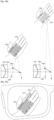
- the wearable device 100 may set an input region by recognizing a certain object.
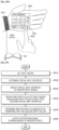
- the wearable device 100 may recognize a palm 410 by using the image sensor 111.
- information about a shape or size of the palm 410 may be pre-stored in the wearable device 100.
- the wearable device 100 may compare the shape and size of the palm 410 with the pre-stored information, and determine whether to set the palm 410 as the input region.
- the wearable device 100 may recognize the palm 410 and sets the input region.
- the wearable device 100 may set the input region by recognizing any one of various objects, such as a desk and a notepad.
- the wearable device 100 may define a certain shape as a marker, and set a plane of an actual object including the marker as an input region when the marker is recognized.
- the wearable device 100 may recognize the rectangle as the marker by using the image sensor 111. As shown in FIG. 4B , the wearable device 100 may recognize a notepad in a rectangle 430 as the marker.
- the wearable device 100 may set a plane of an actual object including the marker as an input region. For example, as shown in FIG. 4B , the wearable device 100 may set a plane of the notepad in the rectangle 430 as an input region. Here, the wearable device 100 may set an entire plane of the notepad as the input region, or a partial region of the plane of the notepad as the input region.
- a rectangle may be defined as the marker.
- any one of various shapes, such as a circle and a polygon, may be defined as the marker.
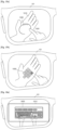
- the wearable device 100 may set an input region by recognizing an actual input interface.
- the wearable device 100 may recognize the actual input interface and display a virtual input interface having the same type as the actual input interface. Also, the wearable device 100 may receive an input of touching the actual input interface by a user using an input tool 520, such as a pen, a stick, a stylus or a finger, and then recognize the actual input interface.
- an input tool 520 such as a pen, a stick, a stylus or a finger
- the actual input interface examples include an actual keyboard, an actual keypad, an actual notepad interface, an actual calculator, an actual piano keyboard, an actual game controller, and an actual dial panel, but are not limited thereto.
- the actual input interface may be a GUI displayed on a mobile terminal.
- the wearable device 100 may recognize the actual keyboard 510 touched by the input tool 520. At this time, the wearable device 100 may obtain a depth value of the actual keyboard 510 and a depth value of the input tool 520 by using the depth sensor 112, and determine that the actual keyboard 510 is touched when a difference between the depth value of the actual keyboard 510 and the depth value of the input tool 520 is equal to or less than a threshold value.
- the wearable device 100 may display a virtual keyboard having the same size and shape as the actual keyboard 510 such that the virtual keyboard overlaps a region where the actual keyboard 510 is displayed.
- the wearable device 100 may recognize a plane of an actual object and set an input region.
- the wearable device 100 may set the plane 540 touched by the input tool 530 as an input region.
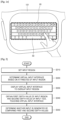
- FIG. 6 is a flowchart illustrating a method of providing a virtual input interface according to a depth value of an input region, according to an exemplary embodiment.
- the wearable device 100 may set an input region based on a user motion, in operation S610. Because operation S610 has been described above in detail with reference to operation S210 of FIG. 2 , and FIGS. 3A through 5B , details thereof are not repeated.
- the wearable device 100 may obtain a depth value of the input region based on the user motion of setting the input region. For example, when a user draws a figure in the air by using an input tool, the wearable device 100 may obtain a depth value of the input tool drawing the figure by using the depth sensor 112, and set the depth value of the input tool as the first depth value of the input region.
- the wearable device 100 may recognize a gesture of drawing the rectangle as a gesture of setting an input region, and set a region corresponding to the rectangle drawn on the desk 1610 as an input region.
- the wearable device 100 may display the QWERTY keyboard 1620 on the optical display 121 such that the QWERTY keyboard 1620 overlaps a rectangular region of the desk 1610 observed through the optical display 121.
- the wearable device 100 may display the QWERTY keyboard 1620 on the optical display 121 according to a size of the rectangular region.
- the wearable device 100 may display the QWERTY keyboard 1620 on an opaque display.
- the wearable device 100 may set a mobile terminal keyboard 1640 as a virtual input interface.
- the wearable device 100 may display the mobile terminal keyboard 1640 on the optical display 121 to overlap the rectangular region on the palm 1630 observed through the optical display 121.
- the wearable device 100 may display the mobile terminal keyboard 1640 on the optical display 121 according to a size of the rectangular region.
- the wearable device 100 may display the mobile terminal keyboard 1640 on an opaque display.
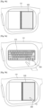
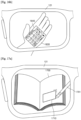
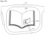
- FIGS. 17A through 17C are diagrams describing a virtual input interface provided by the wearable device 100, the virtual input interface determined based on a type of an actual object where an input region is set, according to an exemplary embodiment.
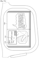
- the wearable device 100 may recognize a type of an actual object where an input region is set, by using the image sensor 111. For example, as shown in FIG. 17A , the wearable device 100 may detect a gesture of the user drawing a rectangle 1710 on the book 1700 by using an input tool 1701, by using the image sensor 111. At this time, the wearable device 100 may identify that the book 1700 is an actual object on which the input region is drawn via an image process, and accordingly, determine a notepad as a virtual input interface corresponding to the book 1700.
- the wearable device 100 may display a virtual notepad 1720 on the optical display 121 such that the virtual notepad 1720 overlaps the input region set on the book 1700 observed through the optical display 121.
- the wearable device 100 may set a blank space of the book 1700, in which text or images are not displayed, as the input region via an image process, and display the virtual notepad 1720 on the optical display 121 such that the virtual notepad 1720 overlaps the blank space observed through the optical display 121.
- the wearable device 100 may obtain a first depth value of the book 1700 and a second depth value of the input tool 1701, and display an input on the virtual notepad 1720 when it is determined that the input is generated based on the first and second depth values.
- the wearable device 100 may store input data 1730 displayed on a virtual notepad based on a user input.
- the user when the user reads the book 1700 while wearing the wearable device 100, the user may easily store important information by using a virtual notepad.
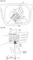
- FIGS. 18A and 18B are diagrams describing a virtual input interface, the virtual input interface determined based on an input tool that sets an input region, according to an exemplary embodiment.
- the user may draw a figure (for example, a rectangle) for setting an input region in the air or on an actual object, by using an input tool, such as a finger or a pen.
- a figure for example, a rectangle
- an input tool such as a finger or a pen.
- the wearable device 100 may recognize a gesture of drawing the rectangle by using the input tool, as a gesture of setting an input region, and set the rectangle drawn in the air or on the actual object as the input region.
- the wearable device 100 may determine a virtual input interface based on the input tool setting the input region.
- the wearable device 100 may determine a mobile terminal keyboard 1830 that is easily touched by the finger 1820 as a virtual input interface.
- the wearable device 100 may display the mobile terminal keyboard 1830 on the optical display 121 to overlap the input region 1810 observed through the optical display 121.
- the wearable device 100 may display the mobile terminal keyboard 1830 on an opaque display.
- the wearable device 100 may determine a handwriting input window 1860 easily used by the pen 1850 as a virtual input interface.
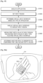
- FIG. 19 is a flowchart illustrating a method of providing a virtual input interface determined based on an application being executed by the wearable device 100, according to an exemplary embodiment.
- the wearable device 100 may execute an application in operation S1910.
- the wearable device 100 may select and execute any one of a plurality of applications provided in the wearable device 100.
- the user may execute an application by using a voice input or a key input.
- the wearable device 100 may execute a message application.
- the message may be a text message, an instant message, a chatting message, or an email.
- the wearable device 100 may receive a message from the external device, and execute the message application in order to respond to or view the received message.
- the wearable device 100 may receive a gesture and, in operation S1920, set an input region based on the gesture. Because operation S1920 has been described above in detail with reference to operation S210 of FIG. 2 and FIGS. 3A through 5B , details thereof are not repeated.
- the wearable device 100 may determine a virtual input interface based on a type of the application being executed.
- the wearable device 100 may determine a virtual keyboard, such as a QWERTY keyboard or a mobile terminal keyboard, as a virtual input interface.
- a virtual keyboard such as a QWERTY keyboard or a mobile terminal keyboard
- the wearable device 100 may determine a virtual dial pad as a virtual input interface, as will be described in detail later with reference to FIGS. 20A and 20B .
- the wearable device 100 may display the virtual input interface to overlap the input region, in operation S1940.
- the wearable device 100 may display the virtual input interface in the form of AR, MR, or VR.
- the wearable device 100 displays the virtual input interface in the form of AR or MR
- the virtual input interface may be displayed on a transparent display to overlap the input region.
- the wearable device 100 displays the virtual input interface in the form of VR
- the virtual input interface may be displayed on an opaque display to overlap the input region.
- the wearable device 100 may obtain a first depth value of the input region and a second depth value of the input tool touching the virtual input interface, in operation S1950.
- the wearable device 100 may determine whether an input is generated through the virtual input interface by comparing the first and second depth values, in operation S1960.
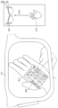
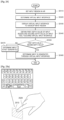
- FIGS. 20A and 20B are diagrams describing providing a virtual input interface determined based on a type of an application being executed, according to an exemplary embodiment.
- the wearable device 100 may execute a call application based on a user input.
- the call application may be executed by using a voice input or a key input.
- the user may set an input region to display a virtual input interface to input a phone number of a person the user wants to call.
- the wearable device 100 may recognize a gesture of the user drawing the input region on a palm 2010, and set the input region on the palm 2010.
- the wearable device 100 may determine a virtual input interface corresponding to the call application being executed, and as shown in FIG. 20A , display a virtual dial pad 2020 that is the virtual input interface on the optical display 121 such that the virtual dial pad 2020 overlaps the palm 2010 observed through the optical display 121.
- the wearable device 100 may execute a notepad application based on a user input.
- the user may execute the notepad application by using a voice input or a key input.
- the user may set an input region to display a virtual input interface for inputting text.
- the wearable device 100 may recognize a gesture of setting the input region on the palm 2010, and set the input region on the palm 2010.
- FIG. 21 is a diagram describing a virtual input interface determined based on a type of content being executed, according to an exemplary embodiment.
- the wearable device 100 may detect a gesture setting an input region while displaying a webpage 2130. At this time, the wearable device 100 may display a virtual keyboard 2135 to search for information from the webpage 2130 on a transparent or opaque display to overlap the input region.
- FIGS. 22A through 23B are diagrams describing virtual input interfaces that are same as previous virtual input interfaces provided when the wearable device 100 recognizes actual objects where the previous virtual input interfaces were provided, according to exemplary embodiments.
- the wearable device 100 may recognize a gesture of drawing the rectangle 2230 by using the image sensor 111, and set a region corresponding to the rectangle 2230 as an input region.
- the wearable device 100 may determine a type of a virtual input interface to be displayed, based on a type of an application currently being executed. For example, when a notepad application that requires a text input is being executed, the wearable device 100 may determine a mobile terminal keyboard 2250 as the virtual input interface, but an exemplary embodiment is not limited thereto.
- the wearable device 100 may display the mobile terminal keyboard 2250 on the optical display 121 such that the mobile terminal keyboard 2250 overlaps a rectangular region observed through the optical display 121.
- the wearable device 100 may display the mobile terminal keyboard 2250 on an opaque display.
- the wearable device 100 may recognize an object that is the same as an actual object (the palm 2210 of FIG. 22B ) on which the virtual input interface was provided, while executing the notepad application.
- the wearable device 100 may detect the palm 2210 of the user by using the image sensor 111. At this time, the wearable device 100 may identify that the palm 2210 is the actual object (the palm 2210 of FIG. 22B ) on which the virtual input interface was provided, via an image process.
- the wearable device 100 may provide a virtual input interface the same as that previously provided in the input region, as shown in FIG. 23B .
- the user may enable the wearable device 100 to recognize an actual object where a virtual input interface was displayed such that the wearable device 100 provides a virtual input interface that was provided.
- the wearable device 100 may set an input region in the air in operation S2410. For example, as described above with reference to FIG. 3A , the wearable device 100 may recognize a figure drawn by the user in the air by using an input tool, such as a finger, a pen, a stylus or a stick, and set a region corresponding to the figure as an input region.
- an input tool such as a finger, a pen, a stylus or a stick
- the wearable device 100 may determine the virtual input interface based on attributes of the input region.
- the wearable device 100 may determine the virtual input interface to be displayed on the optical display 121 based on at least one of a size of the input region, a shape of the input region, a distance between the input region and the wearable device 100 (a first depth value of the input region), and a gesture of setting the input region.
- the wearable device 100 may determine the virtual input interface based on a type of application or content being executed. For example, when the application being executed requires a text input, the wearable device 100 may determine a virtual keyboard, such as a QWERTY keyboard or a mobile terminal keyboard, as the virtual input interface. Alternatively, when the application being executed requires a numerical input, the wearable device 100 may determine a virtual dial pad as the virtual input interface.
- a virtual keyboard such as a QWERTY keyboard or a mobile terminal keyboard
- the wearable device 100 may determine a virtual dial pad as the virtual input interface.
- wearable device 100 may display the virtual input interface to overlap the input region.
- the wearable device 100 may display the virtual input interface in the form of AR, MR, or VR.
- the wearable device 100 may display the virtual input interface on a transparent display such that the virtual input interface overlaps the input region (a 2D or 3D space of the real world) observed through the transparent display.
- the wearable device 100 may capture a first image (an actual image) including the input region (the 2D or 3D space of the real world), and generate a second image by adding the virtual input interface (a virtual image) to the input region of the first image.
- the wearable device 100 may display the second image in which the virtual input interface overlaps the input region on an opaque display.
- the wearable device 100 may obtain a first depth value of the input region and a second depth value of the input tool touching the virtual input interface, in operation S2440.
- the wearable device 100 may measure a distance (a depth value of the input region, i.e., the first depth value) from the wearable device 100 to the input region by using the depth sensor 112.
- the wearable device 100 may obtain the first depth value of the input region by measuring a depth value of the input tool setting the input region in the air.
- the first depth value may be one of an average depth value of the plurality of depth values, a minimum depth value of the plurality of depth values, or a maximum depth value of the plurality of depth values, but is not limited thereto.
- the wearable device 100 may measure a distance (a depth value of the input tool, i.e., the second depth value) from the wearable device 100 to the input tool touching the virtual input interface, by using the depth sensor 112.
- the second depth value may be one of an average depth value of the plurality of depth values, a minimum depth value of the plurality of depth values, or a maximum depth value of the plurality of depth values, but is not limited thereto.
- a point an end point of the input tool
- the input tool and the virtual input interface contact each other may be the second depth value.
- the wearable device 100 may track the input tool that is moving in real-time by using the depth sensor 112, and calculate the second depth value that changes in real-time.
- the wearable device 100 may compare the first and second depth values in operation S2450.
- the wearable device 100 may determine whether the second depth value is greater than the first depth value, and when it is determined that the second depth value is greater than the first depth value, determine that an input is generated through the virtual input interface, in operation S2460.
- the wearable device 100 may determine that an input is not generated through the virtual input interface, in operation S2470.
- FIGS. 25A and 25B are diagrams describing a method of determining whether an input is generated through a virtual input interface, when an input region is set in the air.
- the wearable device 100 may also measure a first depth value of the virtual keyboard 2510 by using the depth sensor 112.
- the user may input data by touching the virtual keyboard 2510 in the air, by using a finger 2520.
- FIG. 26 is a flowchart illustrating a method of providing a virtual input interface in an input region set in the air or on an actual object, according to an exemplary embodiment.
- the wearable device 100 may display the virtual input interface on a transparent display such that the virtual input interface overlaps the input region.
- the wearable device 100 may display the virtual input interface on an opaque display such that the virtual input interface overlaps the input region.
- the wearable device 100 may obtain a first depth value of the input region and a second depth value of the input tool touching the virtual input interface, in operation S2640.
- the wearable device 100 may obtain the first depth value of the input region by measuring a depth value of the input tool while setting the input region in the air.
- the wearable device 100 may measure a distance (a depth value of the input tool, i.e., the second depth value) from the wearable device 100 to the input tool touching the virtual input interface by using the depth sensor 112.
- the wearable device 100 may track the input tool that is moving in real-time and calculate the second depth value in real-time, by using the depth sensor 112.
- the wearable device 100 may measure a first depth value of the palm 2710 by using the depth sensor 112.
- the user may input data by touching the virtual keyboard 2730 shown on the palm 2710 by using a finger 2720.
- the wearable device 100 may measure a depth value (a second depth value) of the finger 2720 touching the virtual keyboard 2730 to determine whether an input is generated through the virtual keyboard 2730.
- the wearable device 100 may determine that an input is not generated through the virtual keyboard 2730.
- the user may approach the finger 2720 near the virtual keyboard 2730 to select a button displayed on the virtual keyboard 2730.
- the difference between the first and second depth values is smaller than the threshold value, it may be determined that the user is touching the virtual keyboard 2730.
- the wearable device 100 may detect a location of the finger 2720 on the virtual keyboard 2730 by using the image sensor 111.
- the wearable device 100 may determine input data based on the location of the finger 2720. For example, when the finger 2720 passes through an "enter" button on the virtual keyboard 2730, the wearable device 100 may determine that the user selected the "enter” button.
- the wearable device 100 may accurately determine whether an input is generated through a virtual input interface provided in the air, or on an actual object, by comparing a first depth value of an input region set by the user in the air or on the actual object and a second depth value of an input tool (for example, a finger or a pen) touching the virtual input interface.
- a first depth value of an input region set by the user in the air or on the actual object and a second depth value of an input tool (for example, a finger or a pen) touching the virtual input interface.
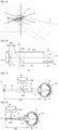
- FIGS. 28A and 28B are diagrams describing a method of obtaining a first depth value of an input region and a second depth value of an input tool, according to an exemplary embodiment.
- the user may set an input region on a left palm 2820 while wearing the wearable device (the first wearable device) 100 in a glasses type, and may be wearing a second wearable device 2810 on a left wrist.
- the second wearable device 2810 may be wearable on a wrist of the user, like a watch, a bracelet, or a band, but is not limited thereto.
- the second wearable device 2810 may include a location sensor, and may sense location information of the second wearable device 2810 by using the location sensor. Also, the first and second wearable devices 100 and 2810 may transmit and receive data to and from each other by including a communicator, and the second wearable device 2810 may transmit the sensed location information of the second wearable device to the first wearable device 100.
- the first wearable device 100 may include a location sensor, and may sense location information of the first wearable device 100 by using the location sensor.
- the first wearable device 100 may compare the sensed location information of the first wearable device 100 with the received location information of the second wearable device 2810 to calculate a distance between the first and second wearable devices 100 and 2810.
- a distance between the left wrist wearing the second wearable device 2810 and the first wearable device 100 may be similar to a distance between the left palm 2820, set as an input region where a virtual keyboard 2840 is displayed, and the first wearable device 100. Accordingly, the first wearable device 100 may determine the distance between the first and second wearable devices 100 and 2810 as a first depth value.
- the first wearable device 100 may accurately obtain the first depth value by using the location information of the second wearable device 2810.
- the second wearable device 2810 may include a motion sensor, and recognize a touch input by detecting motion, such as vibration, generated when the left palm 2820 is touched, by using the motion sensor.
- the second wearable device 2810 may transmit data about the touch input to the first wearable device 100 through the communicator. Accordingly, the first wearable device 100 may accurately recognize that the touch input is generated by using sensing information of the second wearable device 2810.
- the user may set the input region on the left palm 2820 while wearing the first wearable device 100 in a glasses type, and may be wearing a third wearable device 2850 on a right finger 2830.
- the third wearable device 2850 may be wearable on a finger, like a thimble or a ring, but is not limited thereto.
- the first wearable device 100 may include a location sensor, and may sense the location information of the first wearable device 100 by using the location sensor.
- the wearable device 100 may set an input region, in operation S2910.
- the wearable device 100 may output a haptic signal by using a peripheral device.
- the user may be wearing a second wearable device 3150 on the finger 3020 touching the virtual keyboard 3030.
- the second wearable device 3150 may be wearable on the finger 3020, such as a thimble or a ring, but is not limited thereto, as long as the second wearable device 3150 is wearable.
- the second wearable device 3150 may include a haptic module.
- the haptic module may generate various tactile effects.
- An example of the tactile effect generated by the haptic module includes a vibration effect.
- the haptic module When the haptic module generates vibration as a tactile effect, strength and pattern of the vibration may be changed, and different types of vibration may be output, either in combination or sequentially.
- the wearable device 100 may request the second wearable device 3150 to output a haptic signal through a communicator.
- the second wearable device 3150 may output a haptic signal through the haptic module.
- FIG. 32 is a diagram describing outputting of a notification signal corresponding to whether an input is generated through a virtual input interface, according to an exemplary embodiment.
- the wearable device 100 may recognize a gesture of a user setting an input region on a desk 3210, and display a virtual piano keyboard 3220 on a transparent or opaque display to overlap the desk 3210.
- the user may generate an input by touching the virtual piano keyboard 3220 by using a finger 3230.
- the wearable device 100 may compare a depth value (a second depth value) of the finger 3230 with a depth value (a first depth value) of the desk 3210, and determine that an input is generated by the finger 3230 when a difference between the first and second depth values is smaller than a threshold value.
- the wearable device 100 may detect a location of the finger 3230 on the virtual piano keyboard 3220, and display a virtual image 3250 on the virtual piano keyboard 3220 at the location of the finger 3230. As such, the user may easily recognize that the input is generated at a location where the virtual image 3250 is displayed.
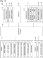
- FIGS. 33 and 34 are block diagrams of the wearable device 100 according to exemplary embodiments.
- the wearable device 100 may include a sensor 110, the optical display 121, and a controller 130.
- components shown in FIG. 33 are not all essential.
- the wearable device 100 may include more or less components than those shown in FIG. 33 .
- the depth sensor 112 may measure a distance from the wearable device 100 to the actual object, and obtain a first depth value of an input region by using the measured distance.
- the microphone 119 receives an external sound signal and processes the external audio signal to electric voice data.
- the microphone 119 may receive the external sound signal from an external device or a person.
- the microphone 119 may use any one of various noise removing algorithms to remove noise generated while receiving the external sound signal.
- acceleration sensor 113 functions of the acceleration sensor 113, the location sensor 114, the atmospheric pressure sensor 115, the temperature/humidity sensor 116, the terrestrial magnetic sensor 117, and the gyroscope sensor 118 are intuitively inferable by one of ordinary skill in the art, details thereof are not provided here.
- the optical display 121 may display information processed by the wearable device 100.
- the optical display 121 may display a user interface (UI) or a graphical user interface (GUI) related to a phone call in a call mode, and display a virtual input interface in an input mode.
- UI user interface
- GUI graphical user interface
- the optical display 121 When the optical display 121 forms a touch screen by forming a layer structure with a touch pad, the optical display 121 may be used as an input device as well as an output device.
- the touch screen may detect a touch gesture of a user on the touch screen, and transmit information about the touch gesture to the controller 130. Examples of the touch gesture include tap, touch and hold, double tap, drag, panning, flick, drag and drop, and swipe.
- the optical display 121 may include at least one of a liquid crystal display, a thin-film transistor-liquid crystal display, an organic light-emitting diode, a flexible display, a 3D display, and an electrophoretic display. Also, the wearable device 100 may include at least two of the optical displays 121 according to a structure of the wearable device 100.
- the sound output 122 outputs audio data received from the communicator 150 or stored in the memory 160. Also, the sound output 122 outputs a sound signal related to a function performed by the wearable device 100, such as a call signal reception sound or a message reception sound.
- the sound output 122 may include a speaker or a buzzer.
- the sound output 122 may output an audio signal corresponding to the input.
- the vibration motor 123 may output a vibration signal.
- the vibration motor 123 may output a vibration signal corresponding to an output of audio data or video data, such as a call signal reception sound or a message reception sound.
- the vibration motor 123 may output a vibration signal.
- the controller 130 generally controls overall operations of the wearable device 100.
- the controller 130 may execute programs stored in the memory 160 to control the sensor 110, the outputter 120, the user input 140, the communicator 150, and the memory 160.
- the controller 130 is configured to set an input region based on a gesture recognized by the image sensor 111. For example, when the image sensor 111 recognizes a gesture of drawing a figure on an actual object, the controller 130 sets a region corresponding to the figure as an input region.
- the controller 130 may determine a type of a virtual input interface based on a first depth value of an input region, and display the virtual input interface on the optical display 121 to overlap the input region.
- the controller 130 may determine a type of a virtual input interface based on a type of an actual object where an input region is set, and display the virtual input interface on the optical display 121 to overlap the input region.
- the controller 130 may determine a type of a virtual input interface based on a type of a gesture setting an input region or a size of the input region, and display the virtual input interface on the optical display 121 to overlap the input region.
- the controller 130 may determine a virtual input interface based on a type of an application being executed by the wearable device 100, and display the virtual input interface on the optical display 121 to overlap an input region.
- the controller 130 may display a virtual input interface on a transparent display such that the virtual input interface is displayed on an input region observed through the transparent display.
- the controller 130 may generate a second image in which a virtual input interface overlaps an input region included in a first image, and display the second image including the virtual input interface on the optical display 121.
- the controller 130 may determine whether an input is generated through a virtual input interface based on a result of comparing a first depth value and a second depth value. For example, the controller 130 may determine that an input is generated through a virtual input interface when a difference between first and second depth values is within a threshold value.
- controller 130 may determine that an input is generated through a virtual input interface.
- the controller 130 may control the outputter 120 to output a notification signal corresponding to generation of an input.
- a user inputs data via the user input 140 to control the wearable device 100.
- the user input 140 may be a keypad, a dome switch, a touch pad (contact capacitance type, pressure resistance film type, infrared light detecting type, acoustic surface wave conducting type, integral tension measuring type, or a piezo-effect type), a jog wheel, or a jog switch, but is not limited thereto.
- the user input 140 may include a virtual input interface.
- the communicator 150 may include at least one component enabling the wearable device 100 to communicate with an external device or a server.
- the communicator 150 may include a local area networker 151, a mobile communicator 152, and a broadcast receiver 153.
Landscapes
- Engineering & Computer Science (AREA)
- General Engineering & Computer Science (AREA)
- Theoretical Computer Science (AREA)
- Physics & Mathematics (AREA)
- General Physics & Mathematics (AREA)
- Human Computer Interaction (AREA)
- Optics & Photonics (AREA)
- Computer Hardware Design (AREA)
- Multimedia (AREA)
- User Interface Of Digital Computer (AREA)
- Computer Graphics (AREA)
- Software Systems (AREA)
Claims (15)
- Brillenartige Wearable-Vorrichtung (100), umfassend:einen Bildsensor (111);eine optische Anzeige (121); undeinen Prozessor (130), der zu Folgendem konfiguriert ist:Steuern des Bildsensors (111), um ein oder mehrere Bilder aufzunehmen, um eine Geste zu erfassen, dass ein Benutzer durch Verwenden eines Eingabewerkzeugs (1701) eine Figur auf einem physischen Objekt zeichnet,Bestimmen einer Benutzereingaberegion, die der durch Verwenden des Eingabewerkzeugs (1701) gezeichneten Figur entspricht,Identifizieren einer Art des physischen Objekts durch Durchführen einer Bildverarbeitung der Benutzereingaberegion undSteuern der optischen Anzeige (121), um eine virtuelle Eingabeschnittstelle basierend auf der Art des physischen Objekts anzuzeigen, wo die Benutzereingaberegion eingestellt ist.
- Brillenartige Wearable-Vorrichtung (100) nach Anspruch 1,
wobei der Prozessor (130) ferner konfiguriert ist zum Steuern der optischen Anzeige (121), um die virtuelle Eingabeschnittstelle durch Überlappen der virtuellen Eingabeschnittstelle auf der Benutzereingaberegion anzuzeigen. - Brillenartige Wearable-Vorrichtung (100) nach Anspruch 1, ferner umfassend:einen Tiefensensor (112), der konfiguriert ist zum Erlangen eines ersten Tiefenwerts, der einem Abstand von der brillenartigen Wearable-Vorrichtung (100) zu der Benutzereingaberegion entspricht, und eines zweiten Tiefenwerts, der einem Abstand von der brillenartigen Wearable-Vorrichtung (100) zu dem Eingabewerkzeug (1701) entspricht,wobei der Prozessor (130) ferner konfiguriert ist zum Bestimmen, ob eine Eingabe durch die virtuelle Eingabeschnittstelle erzeugt wird, basierend auf dem ersten Tiefenwert und dem zweiten Tiefenwert.
- Brillenartige Wearable-Vorrichtung (100) nach Anspruch 3,
wobei eine angezeigte Größe der virtuellen Eingabeschnittstelle basierend auf dem ersten Tiefenwert bestimmt wird. - Brillenartige Wearable-Vorrichtung (100) nach Anspruch 3,
wobei der Prozessor (130) ferner konfiguriert ist zum Bestimmen, dass eine Eingabe durch die virtuelle Eingabeschnittstelle erzeugt wird, wenn eine Differenz zwischen dem ersten Tiefenwert und dem zweiten Tiefenwert kleiner als ein Schwellenwert ist. - Brillenartige Wearable-Vorrichtung (100) nach Anspruch 3,
wobei der Prozessor (130) ferner konfiguriert ist zum Bestimmen, dass eine Eingabe durch die virtuelle Eingabeschnittstelle erzeugt wird, wenn der zweite Tiefenwert größer als der erste Tiefenwert ist. - Brillenartige Wearable-Vorrichtung (100) nach Anspruch 1,
wobei der Prozessor (130) ferner zu Folgendem konfiguriert ist:Bestimmen der virtuellen Eingabeschnittstelle basierend auf einer Art einer Anwendung, die durch die brillenartige Wearable-Vorrichtung (100) ausgeführt wird, undSteuern der optischen Anzeige (121), um die bestimmte virtuelle Eingabeschnittstelle anzuzeigen. - Brillenartige Wearable-Vorrichtung (100) nach Anspruch 1,
wobei die optische Anzeige (121) eine transparente Anzeige umfasst, die konfiguriert ist zum Bereitstellen der virtuellen Eingabeschnittstelle auf einer Region der transparenten Anzeige, die der Benutzereingaberegion entspricht, wie durch die transparente Anzeige betrachtet. - Verfahren zum Bereitstellen einer virtuellen Eingabeschnittstelle durch eine brillenartige Wearable-Vorrichtung (100), wobei das Verfahren Folgendes umfasst:Aufnehmen eines oder mehrerer Bilder durch einen Bildsensor (111) der brillenartigen Wearable-Vorrichtung (100), um eine Geste zu erfassen, dass ein Benutzer durch Verwenden eines Eingabewerkzeugs (1701) eine Figur auf einem physischen Objekt zeichnet;Bestimmen einer Benutzereingaberegion, die der durch Verwenden des Eingabewerkzeugs (1701) gezeichneten Figur entspricht;Identifizieren einer Art des physischen Objekts durch Durchführen einer Bildverarbeitung der Benutzereingaberegion; undAnzeigen einer virtuellen Eingabeschnittstelle auf einer optischen Anzeige (121) der brillenartigen Wearable-Vorrichtung (100) basierend auf der Art des physischen Objekts, wo die Benutzereingaberegion eingestellt ist.
- Verfahren nach Anspruch 9, wobei das Anzeigen der virtuellen Eingabeschnittstelle Folgendes umfasst:
Anzeigen der virtuellen Eingabeschnittstelle auf der optischen Anzeige (121) der brillenartigen Wearable-Vorrichtung (100) durch Überlappen der virtuellen Eingabeschnittstelle auf der Benutzereingaberegion. - Verfahren nach Anspruch 9, ferner umfassend:Erlangen eines ersten Tiefenwerts, der einem Abstand von der brillenartigen Wearable-Vorrichtung (100) zu der Benutzereingaberegion entspricht, und eines zweiten Tiefenwerts, der einem Abstand von der brillenartigen Wearable-Vorrichtung (100) zu dem Eingabewerkzeug (1701) entspricht, durch einen Tiefensensor (112) der brillenartigen Wearable-Vorrichtung (100); undBestimmen, ob eine Eingabe durch die virtuelle Eingabeschnittstelle erzeugt wird, basierend auf dem ersten Tiefenwert und dem zweiten Tiefenwert.
- Verfahren nach Anspruch 11,
wobei eine angezeigte Größe der virtuellen Eingabeschnittstelle basierend auf dem ersten Tiefenwert bestimmt wird. - Verfahren nach Anspruch 11, wobei das Bestimmen, ob die Eingabe erzeugt wird, Folgendes umfasst:
Bestimmen, dass eine Eingabe durch die virtuelle Eingabeschnittstelle erzeugt wird, wenn eine Differenz zwischen dem ersten Tiefenwert und dem zweiten Tiefenwert kleiner als ein Schwellenwert ist. - Verfahren nach Anspruch 11, wobei das Bestimmen, ob die Eingabe erzeugt wird, Folgendes umfasst:
Bestimmen, dass eine Eingabe durch die virtuelle Eingabeschnittstelle erzeugt wird, wenn der zweite Tiefenwert größer als der erste Tiefenwert ist. - Verfahren nach Anspruch 9, ferner umfassend:
Bestimmen der virtuellen Eingabeschnittstelle basierend auf einer Art einer Anwendung, die durch die brillenartige Wearable-Vorrichtung (100) ausgeführt wird.
Applications Claiming Priority (5)
| Application Number | Priority Date | Filing Date | Title |
|---|---|---|---|
| KR20140033705 | 2014-03-21 | ||
| KR1020140098653A KR20150110257A (ko) | 2014-03-21 | 2014-07-31 | 웨어러블 디바이스에서 가상의 입력 인터페이스를 제공하는 방법 및 이를 위한 웨어러블 디바이스 |
| KR1020140179354A KR102360176B1 (ko) | 2014-03-21 | 2014-12-12 | 웨어러블 디바이스에서 가상의 입력 인터페이스를 제공하는 방법 및 이를 위한 웨어러블 디바이스 |
| EP15733329.5A EP2946266B1 (de) | 2014-03-21 | 2015-03-17 | Verfahren und tragbare vorrichtung zur bereitstellung einer virtuellen eingabeschnittstelle |
| PCT/KR2015/002554 WO2015142023A1 (en) | 2014-03-21 | 2015-03-17 | Method and wearable device for providing a virtual input interface |
Related Parent Applications (2)
| Application Number | Title | Priority Date | Filing Date |
|---|---|---|---|
| EP15733329.5A Division EP2946266B1 (de) | 2014-03-21 | 2015-03-17 | Verfahren und tragbare vorrichtung zur bereitstellung einer virtuellen eingabeschnittstelle |
| EP15733329.5A Division-Into EP2946266B1 (de) | 2014-03-21 | 2015-03-17 | Verfahren und tragbare vorrichtung zur bereitstellung einer virtuellen eingabeschnittstelle |
Publications (3)
| Publication Number | Publication Date |
|---|---|
| EP4239456A1 EP4239456A1 (de) | 2023-09-06 |
| EP4239456C0 EP4239456C0 (de) | 2025-07-09 |
| EP4239456B1 true EP4239456B1 (de) | 2025-07-09 |
Family
ID=54142634
Family Applications (2)
| Application Number | Title | Priority Date | Filing Date |
|---|---|---|---|
| EP23173471.6A Active EP4239456B1 (de) | 2014-03-21 | 2015-03-17 | Verfahren und brillenartige tragbare-vorrichtung zur bereitstellung einer virtuellen eingabeschnittstelle |
| EP15733329.5A Active EP2946266B1 (de) | 2014-03-21 | 2015-03-17 | Verfahren und tragbare vorrichtung zur bereitstellung einer virtuellen eingabeschnittstelle |
Family Applications After (1)
| Application Number | Title | Priority Date | Filing Date |
|---|---|---|---|
| EP15733329.5A Active EP2946266B1 (de) | 2014-03-21 | 2015-03-17 | Verfahren und tragbare vorrichtung zur bereitstellung einer virtuellen eingabeschnittstelle |
Country Status (3)
| Country | Link |
|---|---|
| US (3) | US9829986B2 (de) |
| EP (2) | EP4239456B1 (de) |
| WO (1) | WO2015142023A1 (de) |
Families Citing this family (97)
| Publication number | Priority date | Publication date | Assignee | Title |
|---|---|---|---|---|
| US9671566B2 (en) | 2012-06-11 | 2017-06-06 | Magic Leap, Inc. | Planar waveguide apparatus with diffraction element(s) and system employing same |
| WO2015006784A2 (en) | 2013-07-12 | 2015-01-15 | Magic Leap, Inc. | Planar waveguide apparatus with diffraction element(s) and system employing same |
| US10228242B2 (en) | 2013-07-12 | 2019-03-12 | Magic Leap, Inc. | Method and system for determining user input based on gesture |
| CN104391646B (zh) * | 2014-11-19 | 2017-12-26 | 百度在线网络技术(北京)有限公司 | 调整对象属性信息的方法及装置 |
| US20160178906A1 (en) * | 2014-12-19 | 2016-06-23 | Intel Corporation | Virtual wearables |
| JP2018513455A (ja) * | 2015-04-21 | 2018-05-24 | イマージョン コーポレーションImmersion Corporation | エッチング入力の動的表現 |
| AU2015394001C1 (en) * | 2015-05-05 | 2018-12-06 | Razer (Asia-Pacific) Pte. Ltd. | Methods for controlling a headset device, headset devices, computer readable media, and infrared sensors |
| US10401966B2 (en) | 2015-05-15 | 2019-09-03 | Atheer, Inc. | Method and apparatus for applying free space input for surface constrained control |
| US9442575B1 (en) * | 2015-05-15 | 2016-09-13 | Atheer, Inc. | Method and apparatus for applying free space input for surface constrained control |
| CN107615214B (zh) * | 2015-05-21 | 2021-07-13 | 日本电气株式会社 | 界面控制系统、界面控制装置、界面控制方法及程序 |
| CN108027656B (zh) * | 2015-09-28 | 2021-07-06 | 日本电气株式会社 | 输入设备、输入方法和程序 |
| CN105549879A (zh) * | 2015-12-08 | 2016-05-04 | 联想(北京)有限公司 | 一种信息处理方法及电子设备 |
| CN107250950A (zh) * | 2015-12-30 | 2017-10-13 | 深圳市柔宇科技有限公司 | 头戴式显示设备、头戴式显示系统及输入方法 |
| US10963159B2 (en) * | 2016-01-26 | 2021-03-30 | Lenovo (Singapore) Pte. Ltd. | Virtual interface offset |
| US10163198B2 (en) * | 2016-02-26 | 2018-12-25 | Samsung Electronics Co., Ltd. | Portable image device for simulating interaction with electronic device |
| US20170285765A1 (en) * | 2016-03-29 | 2017-10-05 | Seiko Epson Corporation | Input apparatus, input method, and computer program |
| CN105867656B (zh) * | 2016-04-27 | 2019-03-08 | 牛亚锋 | 一种基于体感音乐穿戴设备的演奏动作识别方法 |
| US10049650B2 (en) * | 2016-09-23 | 2018-08-14 | Intel Corporation | Ultra-wide band (UWB) radio-based object sensing |
| US10593116B2 (en) | 2016-10-24 | 2020-03-17 | Snap Inc. | Augmented reality object manipulation |
| US11487353B2 (en) * | 2016-11-14 | 2022-11-01 | Logitech Europe S.A. | Systems and methods for configuring a hub-centric virtual/augmented reality environment |
| US10147243B2 (en) * | 2016-12-05 | 2018-12-04 | Google Llc | Generating virtual notation surfaces with gestures in an augmented and/or virtual reality environment |
| US10242503B2 (en) | 2017-01-09 | 2019-03-26 | Snap Inc. | Surface aware lens |
| US20180210628A1 (en) | 2017-01-23 | 2018-07-26 | Snap Inc. | Three-dimensional interaction system |
| WO2018146922A1 (ja) * | 2017-02-13 | 2018-08-16 | ソニー株式会社 | 情報処理装置、情報処理方法、及びプログラム |
| US20180239422A1 (en) * | 2017-02-17 | 2018-08-23 | International Business Machines Corporation | Tracking eye movements with a smart device |
| KR102079135B1 (ko) * | 2017-04-28 | 2020-02-19 | 주식회사 엘지화학 | 투과율 가변 장치 |
| WO2019000430A1 (en) * | 2017-06-30 | 2019-01-03 | Guangdong Virtual Reality Technology Co., Ltd. | ELECTRONIC SYSTEMS AND TEXT INPUT METHODS IN A VIRTUAL ENVIRONMENT |
| US10591730B2 (en) * | 2017-08-25 | 2020-03-17 | II Jonathan M. Rodriguez | Wristwatch based interface for augmented reality eyewear |
| US10812422B2 (en) | 2017-08-31 | 2020-10-20 | Rpx Corporation | Directional augmented reality system |
| KR102431712B1 (ko) * | 2017-09-04 | 2022-08-12 | 삼성전자 주식회사 | 전자장치, 그 제어방법 및 그 컴퓨터프로그램제품 |
| EP3474120B1 (de) * | 2017-10-18 | 2024-03-20 | AR Technology GmbH | Eingabevorrichtung für computer |
| US10553031B2 (en) | 2017-12-06 | 2020-02-04 | Microsoft Technology Licensing, Llc | Digital project file presentation |
| US10719173B2 (en) * | 2018-04-04 | 2020-07-21 | Facebook Technologies, Llc | Transcribing augmented reality keyboard input based on hand poses for improved typing accuracy |
| US10839603B2 (en) * | 2018-04-30 | 2020-11-17 | Microsoft Technology Licensing, Llc | Creating interactive zones in virtual environments |
| US10770036B2 (en) * | 2018-08-27 | 2020-09-08 | Lenovo (Singapore) Pte. Ltd. | Presentation of content on left and right eye portions of headset |
| US11030813B2 (en) | 2018-08-30 | 2021-06-08 | Snap Inc. | Video clip object tracking |
| EP3654142B1 (de) * | 2018-11-14 | 2025-01-29 | Nokia Technologies Oy | Perspektivisch vermittelte realität aus der ich-perspektive |
| US11176737B2 (en) | 2018-11-27 | 2021-11-16 | Snap Inc. | Textured mesh building |
| CN111309142B (zh) * | 2018-12-11 | 2024-11-22 | 托比股份公司 | 用于切换显示设备的输入模态的方法和设备 |
| CN113330484B (zh) | 2018-12-20 | 2025-08-05 | 斯纳普公司 | 虚拟表面修改 |
| US10902250B2 (en) * | 2018-12-21 | 2021-01-26 | Microsoft Technology Licensing, Llc | Mode-changeable augmented reality interface |
| KR102782794B1 (ko) | 2018-12-26 | 2025-03-19 | 삼성전자주식회사 | 진정 사용자의 손을 식별하는 방법 및 이를 위한 웨어러블 기기 |
| US10984575B2 (en) | 2019-02-06 | 2021-04-20 | Snap Inc. | Body pose estimation |
| WO2020209624A1 (en) * | 2019-04-11 | 2020-10-15 | Samsung Electronics Co., Ltd. | Head mounted display device and operating method thereof |
| US11137908B2 (en) * | 2019-04-15 | 2021-10-05 | Apple Inc. | Keyboard operation with head-mounted device |
| JP7345128B2 (ja) * | 2019-05-20 | 2023-09-15 | パナソニックIpマネジメント株式会社 | 歩行者装置および交通安全支援方法 |
| JP7157244B2 (ja) * | 2019-05-22 | 2022-10-19 | マクセル株式会社 | ヘッドマウントディスプレイ |
| US10890983B2 (en) | 2019-06-07 | 2021-01-12 | Facebook Technologies, Llc | Artificial reality system having a sliding menu |
| US11334212B2 (en) | 2019-06-07 | 2022-05-17 | Facebook Technologies, Llc | Detecting input in artificial reality systems based on a pinch and pull gesture |
| JP2021002288A (ja) * | 2019-06-24 | 2021-01-07 | 株式会社ソニー・インタラクティブエンタテインメント | 画像処理装置、コンテンツ処理システム、および画像処理方法 |
| US11189098B2 (en) | 2019-06-28 | 2021-11-30 | Snap Inc. | 3D object camera customization system |
| US11029845B2 (en) * | 2019-07-11 | 2021-06-08 | Microsoft Technology Licensing, Llc | Virtual keyboard engagement |
| US11232646B2 (en) | 2019-09-06 | 2022-01-25 | Snap Inc. | Context-based virtual object rendering |
| US11409364B2 (en) * | 2019-09-13 | 2022-08-09 | Facebook Technologies, Llc | Interaction with artificial reality based on physical objects |
| US10991163B2 (en) * | 2019-09-20 | 2021-04-27 | Facebook Technologies, Llc | Projection casting in virtual environments |
| US11189099B2 (en) | 2019-09-20 | 2021-11-30 | Facebook Technologies, Llc | Global and local mode virtual object interactions |
| US12229341B2 (en) * | 2019-09-23 | 2025-02-18 | Apple Inc. | Finger-mounted input devices |
| US11275453B1 (en) | 2019-09-30 | 2022-03-15 | Snap Inc. | Smart ring for manipulating virtual objects displayed by a wearable device |
| AU2020360304A1 (en) * | 2019-09-30 | 2022-05-26 | Learning Squared, Inc. | Language teaching machine |
| US11030820B1 (en) * | 2019-12-05 | 2021-06-08 | Facebook Technologies, Llc | Systems and methods for surface detection |
| US11263817B1 (en) | 2019-12-19 | 2022-03-01 | Snap Inc. | 3D captions with face tracking |
| US11227442B1 (en) | 2019-12-19 | 2022-01-18 | Snap Inc. | 3D captions with semantic graphical elements |
| US11875013B2 (en) * | 2019-12-23 | 2024-01-16 | Apple Inc. | Devices, methods, and graphical user interfaces for displaying applications in three-dimensional environments |
| US11277597B1 (en) | 2020-03-31 | 2022-03-15 | Snap Inc. | Marker-based guided AR experience |
| US11798429B1 (en) | 2020-05-04 | 2023-10-24 | Snap Inc. | Virtual tutorials for musical instruments with finger tracking in augmented reality |
| US11520399B2 (en) | 2020-05-26 | 2022-12-06 | Snap Inc. | Interactive augmented reality experiences using positional tracking |
| US20220050527A1 (en) * | 2020-08-12 | 2022-02-17 | Himax Technologies Limited | Simulated system and method with an input interface |
| US11925863B2 (en) | 2020-09-18 | 2024-03-12 | Snap Inc. | Tracking hand gestures for interactive game control in augmented reality |
| US11660022B2 (en) | 2020-10-27 | 2023-05-30 | Snap Inc. | Adaptive skeletal joint smoothing |
| US11615592B2 (en) | 2020-10-27 | 2023-03-28 | Snap Inc. | Side-by-side character animation from realtime 3D body motion capture |
| US11450051B2 (en) | 2020-11-18 | 2022-09-20 | Snap Inc. | Personalized avatar real-time motion capture |
| US11748931B2 (en) | 2020-11-18 | 2023-09-05 | Snap Inc. | Body animation sharing and remixing |
| US11734894B2 (en) | 2020-11-18 | 2023-08-22 | Snap Inc. | Real-time motion transfer for prosthetic limbs |
| JP7667656B2 (ja) * | 2020-12-25 | 2025-04-23 | 時男 後藤 | 手術支援用三次元アノテーション描写システム |
| KR20230124732A (ko) | 2020-12-29 | 2023-08-25 | 스냅 인코포레이티드 | 가상 및 그래픽 엘리먼트들을 제어하기 위한 미세 손제스처들 |
| EP4272051A1 (de) | 2020-12-30 | 2023-11-08 | Snap, Inc. | Präzisionsverfolgung und anzeige für erweiterte realität |
| US11656690B2 (en) * | 2021-03-05 | 2023-05-23 | MediVis, Inc. | User input and virtual touch pad in augmented reality for use in surgical settings |
| US11531402B1 (en) | 2021-02-25 | 2022-12-20 | Snap Inc. | Bimanual gestures for controlling virtual and graphical elements |
| US12353632B2 (en) * | 2021-04-08 | 2025-07-08 | Snap Inc. | Bimanual interactions between mapped hand regions for controlling virtual and graphical elements |
| KR20230170086A (ko) | 2021-04-19 | 2023-12-18 | 스냅 인코포레이티드 | 가상 및 그래픽 엘리먼트들을 애니메이팅하고 제어하기 위한 손 제스처 |
| WO2023034070A1 (en) * | 2021-08-30 | 2023-03-09 | Chinook Labs Llc | Method and device for invoking a writing surface |
| US20250036240A1 (en) * | 2021-12-07 | 2025-01-30 | Telefonaktiebolaget Lm Ericsson (Publ) | Rendering of Virtual Keyboards in Virtual Environments |
| KR20230088100A (ko) | 2021-12-10 | 2023-06-19 | 삼성전자주식회사 | 가상 입력 장치를 이용하기 위한 전자 장치 및 그 전자 장치에서의 동작 방법 |
| US11880947B2 (en) | 2021-12-21 | 2024-01-23 | Snap Inc. | Real-time upper-body garment exchange |
| US12198398B2 (en) | 2021-12-21 | 2025-01-14 | Snap Inc. | Real-time motion and appearance transfer |
| US12223672B2 (en) | 2021-12-21 | 2025-02-11 | Snap Inc. | Real-time garment exchange |
| US12360663B2 (en) * | 2022-04-26 | 2025-07-15 | Snap Inc. | Gesture-based keyboard text entry |
| US12327302B2 (en) | 2022-05-18 | 2025-06-10 | Snap Inc. | Hand-tracked text selection and modification |
| US12373096B2 (en) | 2022-05-31 | 2025-07-29 | Snap Inc. | AR-based virtual keyboard |
| US12288298B2 (en) * | 2022-06-21 | 2025-04-29 | Snap Inc. | Generating user interfaces displaying augmented reality graphics |
| US20240219997A1 (en) * | 2023-01-03 | 2024-07-04 | Meta Platforms Technologies, Llc | Extended Reality User Interfaces for Hand-based Input |
| US12387449B1 (en) | 2023-02-08 | 2025-08-12 | Meta Platforms Technologies, Llc | Facilitating system user interface (UI) interactions in an artificial reality (XR) environment |
| US12400414B2 (en) | 2023-02-08 | 2025-08-26 | Meta Platforms Technologies, Llc | Facilitating system user interface (UI) interactions in an artificial reality (XR) environment |
| US12333658B2 (en) | 2023-02-21 | 2025-06-17 | Snap Inc. | Generating user interfaces displaying augmented reality graphics |
| EP4443272A1 (de) * | 2023-04-05 | 2024-10-09 | Meta Platforms Technologies, LLC | Freihandtypisierung für erweiterte realität |
| US11991222B1 (en) | 2023-05-02 | 2024-05-21 | Meta Platforms Technologies, Llc | Persistent call control user interface element in an artificial reality environment |
| WO2025080265A1 (en) * | 2023-10-11 | 2025-04-17 | Google Llc | Writing on virtual annotation surface |
Family Cites Families (22)
| Publication number | Priority date | Publication date | Assignee | Title |
|---|---|---|---|---|
| US6771294B1 (en) * | 1999-12-29 | 2004-08-03 | Petri Pulli | User interface |
| US6611252B1 (en) * | 2000-05-17 | 2003-08-26 | Dufaux Douglas P. | Virtual data input device |
| JP2002318652A (ja) | 2001-04-20 | 2002-10-31 | Foundation For Nara Institute Of Science & Technology | 仮想入力装置およびプログラム |
| CN101952818B (zh) * | 2007-09-14 | 2016-05-25 | 智慧投资控股81有限责任公司 | 基于姿态的用户交互的处理 |
| US8698753B2 (en) * | 2008-02-28 | 2014-04-15 | Lg Electronics Inc. | Virtual optical input device with feedback and method of controlling the same |
| US20100103104A1 (en) | 2008-10-29 | 2010-04-29 | Electronics And Telecommunications Research Institute | Apparatus for user interface based on wearable computing environment and method thereof |
| KR101284797B1 (ko) | 2008-10-29 | 2013-07-10 | 한국전자통신연구원 | 착용형 컴퓨팅 환경 기반의 사용자 인터페이스 장치 및 그 방법 |
| JP2010145861A (ja) * | 2008-12-19 | 2010-07-01 | Brother Ind Ltd | ヘッドマウントディスプレイ |
| US20110214082A1 (en) | 2010-02-28 | 2011-09-01 | Osterhout Group, Inc. | Projection triggering through an external marker in an augmented reality eyepiece |
| WO2012124844A1 (en) | 2011-03-16 | 2012-09-20 | Lg Electronics Inc. | Method and electronic device for gesture-based key input |
| US9069164B2 (en) * | 2011-07-12 | 2015-06-30 | Google Inc. | Methods and systems for a virtual input device |
| US9497501B2 (en) * | 2011-12-06 | 2016-11-15 | Microsoft Technology Licensing, Llc | Augmented reality virtual monitor |
| US8933912B2 (en) * | 2012-04-02 | 2015-01-13 | Microsoft Corporation | Touch sensitive user interface with three dimensional input sensor |
| KR101947034B1 (ko) * | 2012-08-21 | 2019-04-25 | 삼성전자 주식회사 | 휴대 기기의 입력 장치 및 방법 |
| KR102091710B1 (ko) * | 2012-08-28 | 2020-04-14 | 삼성전자주식회사 | 좌표 측정 장치 및 그 제어 방법 |
| US9378592B2 (en) * | 2012-09-14 | 2016-06-28 | Lg Electronics Inc. | Apparatus and method of providing user interface on head mounted display and head mounted display thereof |
| US8482527B1 (en) | 2012-09-14 | 2013-07-09 | Lg Electronics Inc. | Apparatus and method of providing user interface on head mounted display and head mounted display thereof |
| CN102855839A (zh) * | 2012-09-21 | 2013-01-02 | 京东方科技集团股份有限公司 | 用于消除显示器关机残影的电路 |
| KR102051418B1 (ko) * | 2012-09-28 | 2019-12-03 | 삼성전자주식회사 | 영상에 포함된 객체를 선택하기 위한 사용자 인터페이스 제어 장치 및 그 방법 그리고 영상 입력 장치 |
| KR20140055173A (ko) * | 2012-10-30 | 2014-05-09 | 삼성전자주식회사 | 입력 장치 및 그의 입력 제어 방법 |
| CN103019377A (zh) | 2012-12-04 | 2013-04-03 | 天津大学 | 基于头戴式可视显示设备的输入方法及装置 |
| TWI530819B (zh) * | 2014-02-26 | 2016-04-21 | 宏碁股份有限公司 | 電子裝置與其控制方法 |
-
2015
- 2015-03-17 EP EP23173471.6A patent/EP4239456B1/de active Active
- 2015-03-17 WO PCT/KR2015/002554 patent/WO2015142023A1/en not_active Ceased
- 2015-03-17 EP EP15733329.5A patent/EP2946266B1/de active Active
- 2015-03-23 US US14/665,678 patent/US9829986B2/en active Active
-
2017
- 2017-10-12 US US15/782,505 patent/US10168792B2/en active Active
-
2018
- 2018-12-31 US US16/237,055 patent/US10534442B2/en active Active
Also Published As
| Publication number | Publication date |
|---|---|
| EP2946266A4 (de) | 2016-10-26 |
| US20190138108A1 (en) | 2019-05-09 |
| EP4239456A1 (de) | 2023-09-06 |
| WO2015142023A1 (en) | 2015-09-24 |
| US20150269783A1 (en) | 2015-09-24 |
| US9829986B2 (en) | 2017-11-28 |
| US10534442B2 (en) | 2020-01-14 |
| EP2946266B1 (de) | 2023-06-21 |
| EP2946266A1 (de) | 2015-11-25 |
| EP4239456C0 (de) | 2025-07-09 |
| US20180032146A1 (en) | 2018-02-01 |
| US10168792B2 (en) | 2019-01-01 |
Similar Documents
| Publication | Publication Date | Title |
|---|---|---|
| EP4239456B1 (de) | Verfahren und brillenartige tragbare-vorrichtung zur bereitstellung einer virtuellen eingabeschnittstelle | |
| CN110488974B (zh) | 用于提供虚拟输入界面的方法和可穿戴装置 | |
| KR102360176B1 (ko) | 웨어러블 디바이스에서 가상의 입력 인터페이스를 제공하는 방법 및 이를 위한 웨어러블 디바이스 | |
| US11494000B2 (en) | Touch free interface for augmented reality systems | |
| US9602954B2 (en) | Mobile terminal and method for controlling the same | |
| US9898865B2 (en) | System and method for spawning drawing surfaces | |
| EP3164785B1 (de) | Benutzerschnittstellensteuerung einer wearable-vorrichtung | |
| KR102135367B1 (ko) | 이동 단말기 및 그것의 제어 방법 | |
| KR102499354B1 (ko) | 디스플레이를 통해 표시된 제 1 콘텐트에 대해 제 2 콘텐트를 외부 객체의 움직임에 따라 제공하기 위한 전자 장치 및 그의 동작 방법 | |
| US11360550B2 (en) | IMU for touch detection | |
| KR20170054056A (ko) | 사용자 인터페이스를 제공하는 방법 및 모바일 디바이스 | |
| KR102840430B1 (ko) | 영상에서 평면을 검출하는 전자 장치 및 그 동작 방법 | |
| KR20250023244A (ko) | 가상 환경에서 객체 선택을 지원하는 방법 및 이를 지원하는 전자 장치 | |
| KR20240028897A (ko) | HMD(head mounted display) 장치에서 가상키보드를 표시하는 방법 및 장치 | |
| KR20180097031A (ko) | 휴대 단말 장치와 프로젝션 장치를 포함하는 증강 현실 시스템 |
Legal Events
| Date | Code | Title | Description |
|---|---|---|---|
| PUAI | Public reference made under article 153(3) epc to a published international application that has entered the european phase |
Free format text: ORIGINAL CODE: 0009012 |
|
| STAA | Information on the status of an ep patent application or granted ep patent |
Free format text: STATUS: THE APPLICATION HAS BEEN PUBLISHED |
|
| AC | Divisional application: reference to earlier application |
Ref document number: 2946266 Country of ref document: EP Kind code of ref document: P |
|
| AK | Designated contracting states |
Kind code of ref document: A1 Designated state(s): AL AT BE BG CH CY CZ DE DK EE ES FI FR GB GR HR HU IE IS IT LI LT LU LV MC MK MT NL NO PL PT RO RS SE SI SK SM TR |
|
| STAA | Information on the status of an ep patent application or granted ep patent |
Free format text: STATUS: REQUEST FOR EXAMINATION WAS MADE |
|
| 17P | Request for examination filed |
Effective date: 20231204 |
|
| RBV | Designated contracting states (corrected) |
Designated state(s): AL AT BE BG CH CY CZ DE DK EE ES FI FR GB GR HR HU IE IS IT LI LT LU LV MC MK MT NL NO PL PT RO RS SE SI SK SM TR |
|
| GRAP | Despatch of communication of intention to grant a patent |
Free format text: ORIGINAL CODE: EPIDOSNIGR1 |
|
| STAA | Information on the status of an ep patent application or granted ep patent |
Free format text: STATUS: GRANT OF PATENT IS INTENDED |
|
| INTG | Intention to grant announced |
Effective date: 20250214 |
|
| GRAS | Grant fee paid |
Free format text: ORIGINAL CODE: EPIDOSNIGR3 |
|
| GRAA | (expected) grant |
Free format text: ORIGINAL CODE: 0009210 |
|
| STAA | Information on the status of an ep patent application or granted ep patent |
Free format text: STATUS: THE PATENT HAS BEEN GRANTED |
|
| AC | Divisional application: reference to earlier application |
Ref document number: 2946266 Country of ref document: EP Kind code of ref document: P |
|
| AK | Designated contracting states |
Kind code of ref document: B1 Designated state(s): AL AT BE BG CH CY CZ DE DK EE ES FI FR GB GR HR HU IE IS IT LI LT LU LV MC MK MT NL NO PL PT RO RS SE SI SK SM TR |
|
| REG | Reference to a national code |
Ref country code: GB Ref legal event code: FG4D |
|
| REG | Reference to a national code |
Ref country code: CH Ref legal event code: EP |
|
| REG | Reference to a national code |
Ref country code: IE Ref legal event code: FG4D |
|
| REG | Reference to a national code |
Ref country code: DE Ref legal event code: R096 Ref document number: 602015091995 Country of ref document: DE |
|
| U01 | Request for unitary effect filed |
Effective date: 20250724 |
|
| U07 | Unitary effect registered |
Designated state(s): AT BE BG DE DK EE FI FR IT LT LU LV MT NL PT RO SE SI Effective date: 20250731 |