EP4045743B1 - Serrure à cylindre et dispositif de verrouillage - Google Patents
Serrure à cylindre et dispositif de verrouillage Download PDFInfo
- Publication number
- EP4045743B1 EP4045743B1 EP21719866.2A EP21719866A EP4045743B1 EP 4045743 B1 EP4045743 B1 EP 4045743B1 EP 21719866 A EP21719866 A EP 21719866A EP 4045743 B1 EP4045743 B1 EP 4045743B1
- Authority
- EP
- European Patent Office
- Prior art keywords
- core
- core pin
- housing
- cylinder lock
- key
- Prior art date
- Legal status (The legal status is an assumption and is not a legal conclusion. Google has not performed a legal analysis and makes no representation as to the accuracy of the status listed.)
- Active
Links
- 125000006850 spacer group Chemical group 0.000 claims description 40
- 230000007704 transition Effects 0.000 claims description 11
- 238000006073 displacement reaction Methods 0.000 claims description 4
- 230000037431 insertion Effects 0.000 claims 1
- 238000003780 insertion Methods 0.000 claims 1
- 230000000903 blocking effect Effects 0.000 description 17
- 230000000694 effects Effects 0.000 description 2
- 238000003801 milling Methods 0.000 description 2
- 230000000284 resting effect Effects 0.000 description 2
- 230000004888 barrier function Effects 0.000 description 1
- 230000015572 biosynthetic process Effects 0.000 description 1
- 210000003746 feather Anatomy 0.000 description 1
- 230000003993 interaction Effects 0.000 description 1
- 238000005192 partition Methods 0.000 description 1
Images


Classifications
-
- E—FIXED CONSTRUCTIONS
- E05—LOCKS; KEYS; WINDOW OR DOOR FITTINGS; SAFES
- E05B—LOCKS; ACCESSORIES THEREFOR; HANDCUFFS
- E05B27/00—Cylinder locks or other locks with tumbler pins or balls that are set by pushing the key in
- E05B27/0078—Asymmetrical tumbler pins, e.g. with a key operating on a radial protrusion of a tumbler pin
-
- E—FIXED CONSTRUCTIONS
- E05—LOCKS; KEYS; WINDOW OR DOOR FITTINGS; SAFES
- E05B—LOCKS; ACCESSORIES THEREFOR; HANDCUFFS
- E05B27/00—Cylinder locks or other locks with tumbler pins or balls that are set by pushing the key in
- E05B27/0003—Details
- E05B27/0017—Tumblers or pins
-
- E—FIXED CONSTRUCTIONS
- E05—LOCKS; KEYS; WINDOW OR DOOR FITTINGS; SAFES
- E05B—LOCKS; ACCESSORIES THEREFOR; HANDCUFFS
- E05B27/00—Cylinder locks or other locks with tumbler pins or balls that are set by pushing the key in
- E05B27/0042—Cylinder locks or other locks with tumbler pins or balls that are set by pushing the key in with additional key identifying function, e.g. with use of additional key operated rotor-blocking elements, not of split pin tumbler type
-
- E—FIXED CONSTRUCTIONS
- E05—LOCKS; KEYS; WINDOW OR DOOR FITTINGS; SAFES
- E05B—LOCKS; ACCESSORIES THEREFOR; HANDCUFFS
- E05B27/00—Cylinder locks or other locks with tumbler pins or balls that are set by pushing the key in
- E05B27/0053—Cylinder locks or other locks with tumbler pins or balls that are set by pushing the key in for use with more than one key, e.g. master-slave key
-
- E—FIXED CONSTRUCTIONS
- E05—LOCKS; KEYS; WINDOW OR DOOR FITTINGS; SAFES
- E05B—LOCKS; ACCESSORIES THEREFOR; HANDCUFFS
- E05B35/00—Locks for use with special keys or a plurality of keys ; keys therefor
-
- E—FIXED CONSTRUCTIONS
- E05—LOCKS; KEYS; WINDOW OR DOOR FITTINGS; SAFES
- E05B—LOCKS; ACCESSORIES THEREFOR; HANDCUFFS
- E05B47/00—Operating or controlling locks or other fastening devices by electric or magnetic means
- E05B47/0038—Operating or controlling locks or other fastening devices by electric or magnetic means using permanent magnets
- E05B47/0044—Cylinder locks with magnetic tumblers
Definitions
- the invention relates to a cylinder lock and a locking device according to the preambles of the independent claims.
- cylinder locks are known with a cylinder core that can be rotated in a housing about an axis of rotation D, comprising a key channel running in a radial plane R for inserting a coded key.
- cylinder locks are known in which, in addition to the conventional core and housing pins running in the radial plane R, further core pins are provided which run in a core pin guide on the side of the key channel, i.e. outside the radial plane R.
- the publication shows EP 2 886 754 A2 such a cylinder lock.
- the publication shows EP 0 557 606 A1 a cylinder lock with an additional core pin that runs essentially normal to the radial plane R but is centrally arranged.
- Further generic cylinder locks with core pin guides extending outside the radial plane R are from the publications US 5,819,566 A as well as EP 2 536 902 A1 known.
- the disadvantage of such cylinder locks is that the core pins running outside the radial plane R have to be moved a long distance due to their eccentric positioning relative to the cylinder core in order to protrude sufficiently into the housing so that a secure locking effect can occur.
- the object of the invention is to overcome the disadvantages of the prior art.
- it is the object of the invention to create a cylinder lock in which a sufficient locking effect can be achieved even through small steps on the key.
- the object of the invention is, among other things, to create a cylinder lock which is as simple as possible and can be produced inexpensively.
- a cylinder lock according to the invention comprises a cylinder core which can be rotated in a housing about an axis of rotation D, comprising a key channel running in a radial plane R for inserting a coded key.
- At least one core pin guide extending outside the radial plane R is provided on one side of the key channel. This can be a substantially cylindrical bore or the like.
- a core pin is provided in the core pin guide, which can be moved along its longitudinal axis in the core pin guide from a blocking position to a release position.
- the core pin is designed in such a way that the rotation of the cylinder core relative to the housing is released when a key assigned to the cylinder lock is inserted into the key channel. This can be achieved by forming a substantially cylindrical gap (also referred to as a dividing plane) between the cylinder core and the housing, which the core pin blocks or releases depending on the coding of the key.
- the core pin can be preloaded in the core pin guide by a spring; However, this is not mandatory.
- the core pin is preferably of essentially cylindrical shape and comprises a core side pointing in the direction of the key channel and designed to query a coding on the key, as well as a housing side pointing in the direction of the housing and designed to engage in a housing recess.
- At least two locking sections projecting to different extents in the direction of the longitudinal axis are provided on the housing side of the core pin, each with a locking surface that runs essentially normal to the longitudinal axis.
- the housing side of the core pin is not linear, but essentially step-shaped.
- the blocking surfaces protrude beyond the cylinder core in the blocking position.
- the locking sections protrude at least partially, preferably completely, into the housing recess.
- the locking surfaces of the core pin are preferably flat, smooth and/or without elevations. If necessary, a transition region can be arranged between the locking sections, which in particular runs obliquely to the longitudinal axis of the core pin.
- both locking surfaces of the core pin protrude into the housing recess, so that movement of the cylinder core relative to the housing is prevented, and in the release position the core pin releases the movement of the cylinder core relative to the housing.
- the core pin In the release position, the core pin can be arranged in the cylinder core, in particular without any projection and/or completely.
- a side is designed in a step-like manner can be understood as meaning a side which comprises at least two steps, which are optionally spaced apart by a transition region.
- the core pin guide can extend transversely, preferably normal to the radial plane R of the cylinder core and can preferably be arranged offset from the axis of rotation D of the cylinder core.
- the offset of the core pin guide can be, for example, half, a third, a quarter or a fifth of the radius of the cylinder core. Due to the step-shaped design of the housing side of the core pin, the offset can be particularly large and it can even be provided that two or more core pins are arranged in a quadrant of the cylinder core cross section.
- the core pin may be substantially cylindrical but may have a non-circular cross section such that it is not rotatable in the core pin guide.
- the core pin can have a shoulder that extends radially outward in sections and is designed to interact positively with a stop in the core pin guide in order to limit the displacement of the core pin in the core pin guide in the direction of the cylinder core.
- the housing recess has a smaller cross section than the core pin guide, so that the core pin can only penetrate into the housing recess with its locking sections, i.e. the locking surfaces.
- the core pin can include a release device which is designed such that the core pin in the core pin guide is moved from the blocking position to the release position when a key assigned to the cylinder lock is inserted into the key channel.
- the release device can preferably be magnetizable and particularly preferably comprise a permanent magnet which is designed to interact with a magnetic coding on the key.
- the core pin can be moved essentially in the direction of its longitudinal axis in the core pin guide by interacting with the release device.
- the release device and the core pin can cooperate in such a way that the core pin is moved in the direction of the key channel or in the direction of the housing, whereby the rotation of the cylinder core relative to the housing is released.
- the release device can be arranged in a recess of the core pin, preferably designed as a blind hole, which is particularly preferably arranged on the core side of the core pin, i.e. adjacent to the key channel.
- the blind hole can preferably be formed symmetrically about the longitudinal axis of the core pin.
- a first control surface can be provided on the core side of the core pin, which is flat and runs essentially normal to the longitudinal axis of the core pin. Furthermore, a second control surface can be provided on the core side of the core pin, which is curved or curved along the longitudinal axis.
- the first control surface on the core side of the core pin can form a first circular ring section.
- the second control surface on the core side of the core pin can form a second circular ring section. Both circular ring sections can cover the outer circumference of the core side of the core pin.
- the control surfaces can in particular be arranged concentrically around the recess, preferably the blind hole.
- the control surfaces can preferably be designed to be offset in steps along the longitudinal axis, so that the second control surface extends further in the direction of the key channel than the first control surface.
- the second control surface can in particular be designed as a web-shaped scanning extension for scanning a slot-shaped coding on the key. This may make it possible to further increase the security of the cylinder lock, since on the one hand the key must be designed to move the core pin and, on the other hand, must have a coding that can interact with the control surface of the core pin. If necessary, the core pin is only moved by the interaction of the key and the control surface.
- a housing pin that is preloaded by a spring and interacts with the core pin can be provided in the housing recess.
- the housing pin can be designed in such a way that it forms a dividing plane between the cylinder core and the housing and releases this when a key assigned to the cylinder lock is inserted into the key channel.
- At least one spacer plate can be provided between the core pin and the housing pin, so that the rotation of the cylinder core relative to the housing is enabled in two or more positions of the core pin.
- the spacer plates enable the formation of two or more independent division planes. This makes it possible in particular to use key systems with different key hierarchies for operating the cylinder lock.
- the spacer plate is also displaced by a displacement of the core pin.
- the at least one core pin, in particular its housing side, or the at least one spacer plate is brought into a position in which the cylinder core can be rotated relative to the housing.
- the housing side of the at least one core pin, the housing side of the at least one spacer plate or the separating surface between the at least one core pin and the at least one spacer plate are preferably aligned with the parting line (partition plane) between the cylinder core and the housing, so that a rotation of the cylinder core relative to the housing is possible if necessary .
- the spacer plate is essentially cylindrical with a longitudinal axis, a front core side and an opposite housing side.
- the core side can rest on the core pin and the housing side on the housing pin or on another spacer plate.
- the core side can be in positive engagement with the housing side of the core pin.
- the core side can preferably be designed essentially step-shaped, in that at least two blocking surfaces are provided on the core side, projecting to different extents along the longitudinal axis and running essentially normal to the longitudinal axis, optionally connected by a transition region.
- At least one blocking surface of the at least one spacer plate can preferably be flat, smooth and/or raised-free.
- the steps on the core side of the spacer plate can be formed by the at least two blocking surfaces.
- a transition region can be arranged between the at least two blocking surfaces on the core side of the spacer plate, which in particular runs obliquely to the longitudinal axis of the spacer plate.
- the spacer plate in particular its core and/or housing side, is preferably designed in such a way that the spacer plate can be positively connected, in particular to the core pin, in particular to the housing side of the core pin, and/or another spacer plate.
- the core side of the spacer plate can essentially correspond to the housing side of the core pin.
- the housing side of the spacer plate can essentially correspond to the core side of another spacer plate.
- the housing side of the spacer plate can also not be step-shaped, but bent, slanted or rounded.
- the spacer plate can be guided together with the core pin. This makes it possible for the spacer plate to be non-rotatably movable in the direction of its longitudinal axis.
- the cylinder lock can also have further query elements for querying any coding on the key.
- a key for a cylinder lock wherein the key has at least one preferably magnetic coding which is designed such that the core pin is moved from the blocking position to the release position when the key is inserted into the key channel.
- the key can also have other codings.
- the invention further relates to a locking device with a cylinder lock according to the invention and such a key.
- Figures 1a and 1b show a schematic representation of a first embodiment of a cylinder lock according to the invention
- Figures 2a and 2b show a schematic representation of a first embodiment of a core pin according to the invention
- Figures 3a and 3b show a schematic representation of a second embodiment of a core pin according to the invention
- Figure 4 shows a schematic representation of a spacer plate
- Figures 5a to 5c show a schematic representation of a section of a second embodiment of a cylinder lock according to the invention
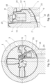
- Figs. 1a and 1b show a schematic graphic representation of a first embodiment of a cylinder lock according to the invention, wherein in the Fig. 1b a part of Fig. 1a is shown enlarged.
- the cylinder lock comprises a housing 1 and a cylinder core 2 rotatably mounted therein. According to this illustration, a key 3 is inserted into the key channel 7 of the cylinder lock.
- the key channel 7 extends in a radial plane R through the axis of rotation D of the cylinder core 2 and has a core pin guide 13 in which a core pin 6 is displaceably arranged.
- the core pin guide 13 is arranged approximately normal to the radial plane R and arranged eccentrically to the axis of rotation D with an offset of approximately one third of the cylinder core radius from the axis of rotation D.
- the core pin guide 13 leads laterally and above the axis of rotation D transversely from the housing 1 through the cylinder core 2 into the key channel 7.
- the core pin 6 is shown in its release position. In this release position, the core pin 6 is arranged within the cylinder core 2 without any projection.
- the dividing surface between the cylinder core 2 and the housing 1 is free and a rotation of the cylinder core 2 relative to the housing 1 is possible.
- the core pin 6 can be brought from this release position into its blocking position, whereby rotation of the cylinder core 2 relative to the housing 1 is blocked.
- the core pin 6 comprises a substantially cylindrical base body on which a shoulder 21 is arranged.
- the shoulder 21 is designed to interact with the cylinder core 2, in particular with a stop 23 in the core pin guide 13, so that the movement of the core pin 6 along its longitudinal axis 5 is limited.
- the core pin 6 has a core side 8 and a housing side 9, which lie opposite each other.
- the core side 8 of the core pin 6 points in the direction of the key channel 7 and is designed to query a coding on the key 3.
- the housing side 9 of the core pin 6 points in the direction of the housing 1 and is designed to engage in a housing recess 24.
- the core side 8 of the core pin 6 has first and second control surfaces 18, 19.
- the control surfaces 18, 19 are set up to query a coding, in particular a notch milling, on a side surface of the key 3.
- the first control surface 18 is designed in the form of a web-shaped scanning element which extends over the second control surface 19.
- the control surfaces 18, 19 of the core side 8 of the core pin 6 run essentially normal to the longitudinal axis of the core pin 6 and are essentially flat.
- the housing side 9 of the core pin 6 is designed in a step-shaped manner according to this embodiment.
- the steps of the housing side 9 of the core pin 6 are formed by two locking sections 4, each of which has a locking surface 10 that is essentially normal to the longitudinal axis 5 of the core pin 6.
- a contact surface 22 is provided adjacent to the locking sections 4.
- the housing recess 24 has a smaller cross section than the core pin guide 13, so that the core pin 6 can only penetrate into the housing recess 24 with its locking sections 4, i.e. the locking surfaces 10.
- the further movement of the core pin 6 in the direction of the housing 1 is limited by the fact that the contact surface 22 on the housing side 9 of the core pin 6 abuts against the inner circumference of the housing 1.
- the core pin 6 includes a release device 11, which is designed such that the core pin 6 is moved from the blocking position to the release position when a key 3 assigned to the cylinder lock is inserted into the key channel 7.
- the release device 11 is designed as a permanent magnet, which is arranged in a blind hole 12 on the core side 8 of the core pin 6.
- FIGS. 2a and 2b show schematic representations of an embodiment of a core pin 6 'according to the invention in a side view and a sectional view.
- This core pin 6 ' is a different embodiment than the one in the Figures 1a and 1b shown core pin 6, although their features can preferably correspond.
- the core pin 6' of this embodiment is substantially cylindrical but has a non-circular cross section due to a radially outwardly extending shoulder 21.
- This shoulder 21 serves to limit the movement of the core pin 6' in the core pin guide 13 by being attached to a Stop 23 strikes in the core pin guide 13.
- the core pin 6 has a core side 8 on the end that points in the direction of the key channel 7 and is designed to query a coding on the key and a housing side 9 that points in the direction of the housing 1 and is designed to engage in a housing recess 24.
- the housing side 9 is therefore stepped-shaped, with the locking surfaces 10 forming the steps.
- a short transition area 20 is provided between the blocking surfaces 10.
- the core pin 6 ' comprises a release device 11, which comprises a permanent magnet which is designed to cooperate with a magnetic coding on the key 3.
- the release device 11 is arranged in a blind hole 12 of the core pin 6', which is arranged on the core side 8 of the core pin 6'.
- the blind hole 12 is arranged essentially centrally and along the longitudinal axis 5 of the core pin 6 'and is delimited by an annular section of the core side 8. This annular section forms a first control surface 18.
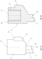
- FIGS 3a and 3b show schematic representations of a second embodiment of a core pin 6 according to the invention in a side view and in a three-dimensional view.
- This embodiment of the core pin 6 is the one in the Figures 1a and 1b shown core pin 6.
- the core pin 6 is in turn essentially cylindrical with a non-circular cross section due to a shoulder 21 that extends radially outwards.
- the core pin 6 has a core side 8 on the end facing in the direction of the key channel 7 and designed for querying a coding on the key and one in the direction of the housing 1 and designed to engage in a housing recess 24.
- the housing side 9 is therefore stepped-shaped, with the locking surfaces 10 forming the steps.
- a short transition area 20 is provided between the blocking surfaces 10.
- not only the housing side 9, but also the core side 8 is essentially step-shaped.
- first control surface 18 on the core side 8 of the core pin 6, which is flat and runs essentially normal to the longitudinal axis 5 of the core pin 6.
- a second control surface 19 is provided on the core side 8, which is curved along the longitudinal axis 5.
- the first and second control surfaces 18, 19 are arranged concentrically around the blind hole 12, thus forming its boundary or edge.
- the first control surface 18 forms a first circular ring section of the core side 8
- the second control surface 19 forms a second circular ring section of the core side 8.
- the first and second control surfaces 18, 19 are designed to be offset in steps along the longitudinal axis 5.
- the second control surface 19 is formed over an angular range of less than 180° and thus forms a web-shaped scanning pin which is designed to be inserted into a corresponding milling cut on the key 3.
- the Figure 4 shows a schematic representation of a spacer plate 15 according to the invention.
- the spacer plate 15 is essentially cylindrical with a longitudinal axis 25, a front core side 16 and an opposite housing side 17.
- the length of the spacer plate 15 is preferably less than its diameter.
- the core side 16 is essentially stepped-shaped in that at least two blocking surfaces 10 are provided on the core side 16, projecting to different extents along the longitudinal axis 25 and running essentially normal to the longitudinal axis 25 and connected by a transition region 20.
- the transition region 20 between the two steps of the core side 16 preferably runs obliquely to the longitudinal axis 25.
- other shapes of the transition region 20, such as, for example, as part of a circular arc are also provided.
- the housing side 17 can also not be designed in a step-shaped manner, but rather linearly and obliquely to the longitudinal axis 25.
- FIGS. 5a to 5c show schematic representations of a further embodiment of a cylinder lock according to the invention.
- the features of the embodiment according to Figures 5a to 5c can preferably correspond to the features of the embodiments according to Figures 1a, 1b , 2a, 2b , 3a, 3b and/or correspond to 4.
- a housing pin 26 which is preloaded by a spring 14 and interacts with the core pin 6 is provided in the housing recess 24.
- the spring 14 presses the core pin 6 in the direction of the key channel 7.
- the spring 14 is arranged in the housing recess 24.
- the housing pin 26 is designed such that it releases a dividing plane between the cylinder core 2 and the housing 1 when a key 3 assigned to the cylinder lock is inserted into the key channel 7.
- a spacer plate 15 is provided between the housing pin 26 and the core pin 6, the core side 16 of the spacer plate 15 resting on the core pin 6 and the housing side 17 resting on the housing pin 26.
- the core side 16 of the spacer plate 15 is therefore in positive engagement with the housing side 9 of the core pin 6.
- two independent division levels are formed, so that two differently coded keys can lock the lock.
- the spacer plate 15 lies with its core side 16 in a form-fitting manner on the housing side 9 of the core pin 6 and, due to the step-shaped design of these sides, is positively connected to the core pin 6. Due to the positive connection, the spacer plate 15 is guided in the housing recess 24 and can be moved along its longitudinal axis 25 without rotation.
- the core pin 6 is in a position in which the separating surface between the core pin 6 and the spacer plate 15 is aligned with the parting line between the cylinder core 2 and the housing 1, so that the cylinder core 2 can be rotated relative to the housing 1.
- the core pin 6 is in a position in which the housing side 17 of the spacer plate 15 is aligned with the joint between the cylinder core 2 and the housing 1, so that a rotation of the cylinder core 2 relative to the housing 1 is also possible.
- the core pin 6 is in a position in which the housing pin 26 blocks the joint between the cylinder core 2 and the housing 1, so that rotation of the cylinder core 2 relative to the housing 1 is not possible. This configuration can be provided in all embodiments.
- the invention is not limited to the illustrated embodiments, but includes any cylinder lock, any key and any locking device according to the following patent claims.
Landscapes
- Lock And Its Accessories (AREA)
Claims (15)
- Serrure à barillet avec un noyau de cylindre (2) pouvant pivoter autour d'un axe de rotation D dans un boîtier (1), comprenant un canal de clé (7) s'étendant dans un plan radial R pour l'introduction d'une clé codée (3),- au moins un guide de broche-noyau (13) s'étendant en dehors du plan radial R étant prévu sur un côté du canal de clé (7),- une broche-noyau (6, 6') étant prévue dans le guide de broche-noyau (13), laquellecaractérisée en ce que∘ peut être déplacée le long de son axe longitudinal (5) dans le guide de broche-noyau (13) d'une position de blocage à une position de dégagement,∘ présente un côté noyau (8) orienté en direction du canal de clé (7) et conçu pour l'interrogation d'un codage sur la clé,∘ présente un côté boîtier (9) orienté en direction du boîtier (1) et conçu pour s'engager dans un évidement de boîtier (24), et∘ est conçue de telle sorte que la rotation du noyau de cylindre (2) par rapport au boîtier (1) est dégagée lorsqu'une clé (3) associée à la serrure à barillet est introduite dans le canal de clé (7),
sur le côté (9) de boîtier sont prévues au moins deux sections (4) de blocage faisant saillie à des distances différentes dans la direction de l'axe longitudinal (5) et ayant chacune une surface de blocage (10) s'étendant sensiblement perpendiculairement à l'axe longitudinal (5), de sorte que le côté de boîtier (9) est réalisé sensiblement en forme étagée, dans la position de blocage, les deux surfaces de blocage (10) de la broche-noyau (6, 6') pénètrent dans l'évidement du boîtier (24), de sorte qu'un mouvement du noyau de cylindre (2) par rapport au boîtier (1) est empêché, et dans la position de dégagement, la broche-noyau (6, 6') libère le mouvement du noyau de cylindre (2) par rapport au boîtier (1). - Serrure à barillet selon la revendication 1, caractérisée en ce que le guide de broche-noyau (13) s'étend transversalement, de préférence perpendiculairement au plan radial R du noyau de cylindre (2) et est de préférence décalé par rapport à l'axe de rotation D du cylindre de serrure (2).
- Serrure à barillet selon la revendication 1 ou 2, caractérisée en ce que la broche-noyau (6, 6') présente une section transversale non circulaire et ne peut pas tourner dans le guide de broche-noyau (13).
- Serrure à barillet selon l'une des revendications 1 à 3, caractérisée en ce que la broche-noyau (6, 6') comprend un dispositif de dégagement (11) qui est conçu de telle sorte que la broche-noyau (6, 6') est déplacée dans le guide de broche-noyau (13) de la position de blocage à la position de dégagement, lorsqu'une clé (3) associée à la serrure à barillet est introduite dans le canal de clé (7), le dispositif de dégagement (11) étant de préférence magnétisable et comprenant de manière particulièrement préférée un aimant permanent qui est conçu pour coopérer avec un codage magnétique sur la clé (3).
- Serrure à barillet selon la revendication 4, caractérisée en ce que le dispositif de dégagement (11) est disposé dans un évidement de la broche-noyau (6, 6'), réalisé de préférence sous la forme d'un trou borgne (12), qui est disposé de manière particulièrement préférée sur le côté noyau (8) de la broche-noyau (6, 6').
- Serrure à barillet selon l'une des revendications 1 à 5, caractérisée en ce qu'une première surface de commande (18) est prévue sur le côté noyau (8) de la broche-noyau (6, 6'), laquelle est plane et s'étend sensiblement perpendiculairement à l'axe longitudinal (5) de la broche-noyau (6, 6').
- Serrure à barillet selon l'une des revendications 1 à 6, caractérisée en ce qu'une deuxième surface de commande (19) est prévue sur le côté noyau (8) de la broche-noyau (6, 6'), laquelle est conçue de manière incurvée le long de l'axe longitudinal (5).
- Serrure à barillet selon la revendication 7 en combinaison avec la revendication 6, caractérisée en ce que la première surface de commande (18) forme une première portion d'anneau circulaire du côté noyau (8) et la deuxième surface de commande (19) forme une deuxième portion d'anneau circulaire du côté noyau (8), les surfaces de commande (18, 19) étant décalées en forme étagée le long de l'axe longitudinal (5).
- Serrure à barillet selon la revendication 8 en combinaison avec la revendication 5, caractérisée en ce que les surfaces de commande (18, 19) sont disposées de manière concentrique autour de l'évidement, de préférence du trou borgne (12).
- Serrure à barillet selon l'une des revendications 1 à 9, caractérisée en ce que la broche-noyau (6, 6') présente une section transversale sensiblement cylindrique avec un épaulement (21) s'étendant radialement vers l'extérieur par sections, qui est conçu pour coopérer par engagement positif avec une butée (23) dans le guide de broche-noyau (13) afin de limiter le déplacement de la broche-noyau (6, 6') dans le guide de broche-noyau (13).
- Serrure à barillet selon l'une des revendications 1 à 10, caractérisée en ce qu'il est prévu dans l'évidement (24) du boîtier une broche-boîtier (26) précontrainte par un ressort (14) et coopérant avec la broche-noyau (6, 6'), qui est conçue de telle sorte qu'elle dégage un plan de joint entre le noyau de cylindre (2) et le boîtier (1) lorsqu'une clé (3) associée à la serrure à barillet est introduite dans le canal de clé (7).
- Serrure à barillet selon la revendication 11, caractérisée en ce qu'au moins une plaquette d'écartement (15) est prévue entre la broche-noyau (6, 6') et la broche-boîtier (26), de sorte que la rotation du noyau de cylindre (2) par rapport au boîtier (1) est dégagée dans deux positions ou plus de la broche-noyau (6, 6').
- Serrure à barillet selon la revendication 12, caractérisée en ce quea. la plaquette d'écartement (15) est sensiblement cylindrique avec un axe longitudinal (25), un côté noyau (16) et un côté boîtier (17),b. le côté noyau (16) est en appui sur la broche-noyau (6, 6') et le côté boîtier (17) est en appui sur la broche-boîtier (26) ou sur une autre plaquette d'écartement (15),c. le côté noyau (16) est en engagement positif avec le côté boîtier (9) de la broche-noyau (6, 6'), et de préférenced. le côté noyau (16) est réalisé essentiellement en forme étagée, en ce que sur le côté noyau (16) sont prévues au moins deux surfaces de blocage (10) faisant saillie à des distances différentes le long de l'axe longitudinal (25), s'étendant essentiellement perpendiculairement à l'axe longitudinal (25), reliées le cas échéant par une zone de transition (20).
- Serrure à barillet selon la revendication 13, caractérisée en ce que le côté boîtier (17) de la plaquette d'écartement (15) n'est pas en forme étagée, mais est courbé, oblique ou arrondi.
- Dispositif de fermeture avec une serrure à barillet selon les revendications 1 à 14 et une clé (3), caractérisé en ce que la clé (3) présente au moins un codage, de préférence magnétique, qui est conçu de telle sorte que la broche-noyau (6, 6') est déplacée de la position de blocage à la position de dégagement lorsque la clé (3) est introduite dans le canal de clé (7).
Applications Claiming Priority (2)
| Application Number | Priority Date | Filing Date | Title |
|---|---|---|---|
| ATA50336/2020A AT523709B1 (de) | 2020-04-20 | 2020-04-20 | Zylinderschloss, Schlüssel und Schließvorrichtung |
| PCT/EP2021/059428 WO2021213829A1 (fr) | 2020-04-20 | 2021-04-12 | Serrure à cylindre, clé et dispositif de verrouillage |
Publications (2)
| Publication Number | Publication Date |
|---|---|
| EP4045743A1 EP4045743A1 (fr) | 2022-08-24 |
| EP4045743B1 true EP4045743B1 (fr) | 2023-11-01 |
Family
ID=75581493
Family Applications (1)
| Application Number | Title | Priority Date | Filing Date |
|---|---|---|---|
| EP21719866.2A Active EP4045743B1 (fr) | 2020-04-20 | 2021-04-12 | Serrure à cylindre et dispositif de verrouillage |
Country Status (3)
| Country | Link |
|---|---|
| EP (1) | EP4045743B1 (fr) |
| AT (1) | AT523709B1 (fr) |
| WO (1) | WO2021213829A1 (fr) |
Family Cites Families (7)
| Publication number | Priority date | Publication date | Assignee | Title |
|---|---|---|---|---|
| DE4205643C2 (de) * | 1992-02-25 | 1994-10-13 | Wilka Schliestechnik Gmbh | Profilzylinder |
| DE29507953U1 (de) * | 1994-09-29 | 1995-07-27 | Evva Werke | Flachschlüssel und Zylinderschloß |
| DE19654136C2 (de) * | 1996-12-23 | 1999-11-18 | Schulte C E Gmbh | Schließzylinder |
| US5823029A (en) * | 1997-01-29 | 1998-10-20 | International Security Products, Inc. | Cylinder lock system |
| US5819566A (en) * | 1997-01-29 | 1998-10-13 | International Security Products, Inc. | Cylinder lock and key |
| DE102010012261B4 (de) * | 2010-03-22 | 2015-08-20 | Abus Pfaffenhain Gmbh | Schließsystem |
| DE102013114423B4 (de) | 2013-12-19 | 2023-05-17 | M. van der Wal Holding B. V. | Schließzylinder mit magnetischem Zuhaltungsstift |
-
2020
- 2020-04-20 AT ATA50336/2020A patent/AT523709B1/de active
-
2021
- 2021-04-12 EP EP21719866.2A patent/EP4045743B1/fr active Active
- 2021-04-12 WO PCT/EP2021/059428 patent/WO2021213829A1/fr unknown
Also Published As
| Publication number | Publication date |
|---|---|
| WO2021213829A1 (fr) | 2021-10-28 |
| AT523709B1 (de) | 2021-11-15 |
| EP4045743A1 (fr) | 2022-08-24 |
| AT523709A4 (de) | 2021-11-15 |
Similar Documents
| Publication | Publication Date | Title |
|---|---|---|
| EP2314807B1 (fr) | Système de verrouillage | |
| EP2603654B1 (fr) | Dispositif de fermeture | |
| EP2310598B1 (fr) | Serrure a pompe comportant un boitier cylindrique et cle plate pour une serrure a pompe | |
| EP3155191B1 (fr) | Serrure à cylindre | |
| EP3061893B1 (fr) | Cle pour barillet et dispositif de verrouillage | |
| EP3814590B1 (fr) | Clé plate pour serrure cylindrique et serrure cylindrique | |
| EP3922788A1 (fr) | Ébauche de clé et clé destinée au fonctionnement d'un cylindre de disque, ainsi que procédé de fabrication d'une telle ébauche de clé et de clé | |
| EP4045743B1 (fr) | Serrure à cylindre et dispositif de verrouillage | |
| DE102013103790B4 (de) | Schließzylinder | |
| EP3092359B1 (fr) | Serrure à cylindre | |
| DE102010012261B4 (de) | Schließsystem | |
| EP3205796B1 (fr) | Clé pour un barillet, barillet et dispositif de fermeture | |
| AT403607B (de) | Schliesseinrichtung mit einem zylinderschloss und einem wendeflachschlüssel | |
| EP3483365B1 (fr) | Clé d'actionnement d'un cylindre de serrure et système de fermeture à clé et à cylindre de serrure | |
| EP3280854B1 (fr) | Clé, ébauche de clé et système de fermeture avec une telle clé et un cylindre de fermeture correspondant | |
| EP3812537B1 (fr) | Cylindre de fermeture | |
| DE2558249A1 (de) | Mittels eines permanentmagnet- schluessels betaetigbares drehzylinderschloss | |
| DE2930425A1 (de) | Zylinderschloss | |
| WO2024108245A1 (fr) | Clé pour une serrure à barillet et serrure à barillet | |
| DE2806072A1 (de) | Schluessel und schloss mit axialen zuhaltestiften | |
| DE202006020501U1 (de) | Zylinderschloss mit einem Schutz gegen Manipulation durch Schlageinwirkung | |
| WO2015000966A1 (fr) | Clé et cylindre rotatif |
Legal Events
| Date | Code | Title | Description |
|---|---|---|---|
| STAA | Information on the status of an ep patent application or granted ep patent |
Free format text: STATUS: UNKNOWN |
|
| STAA | Information on the status of an ep patent application or granted ep patent |
Free format text: STATUS: THE INTERNATIONAL PUBLICATION HAS BEEN MADE |
|
| PUAI | Public reference made under article 153(3) epc to a published international application that has entered the european phase |
Free format text: ORIGINAL CODE: 0009012 |
|
| STAA | Information on the status of an ep patent application or granted ep patent |
Free format text: STATUS: REQUEST FOR EXAMINATION WAS MADE |
|
| 17P | Request for examination filed |
Effective date: 20220519 |
|
| AK | Designated contracting states |
Kind code of ref document: A1 Designated state(s): AL AT BE BG CH CY CZ DE DK EE ES FI FR GB GR HR HU IE IS IT LI LT LU LV MC MK MT NL NO PL PT RO RS SE SI SK SM TR |
|
| P01 | Opt-out of the competence of the unified patent court (upc) registered |
Effective date: 20230509 |
|
| DAV | Request for validation of the european patent (deleted) | ||
| DAX | Request for extension of the european patent (deleted) | ||
| GRAP | Despatch of communication of intention to grant a patent |
Free format text: ORIGINAL CODE: EPIDOSNIGR1 |
|
| STAA | Information on the status of an ep patent application or granted ep patent |
Free format text: STATUS: GRANT OF PATENT IS INTENDED |
|
| INTG | Intention to grant announced |
Effective date: 20230629 |
|
| GRAS | Grant fee paid |
Free format text: ORIGINAL CODE: EPIDOSNIGR3 |
|
| GRAA | (expected) grant |
Free format text: ORIGINAL CODE: 0009210 |
|
| STAA | Information on the status of an ep patent application or granted ep patent |
Free format text: STATUS: THE PATENT HAS BEEN GRANTED |
|
| AK | Designated contracting states |
Kind code of ref document: B1 Designated state(s): AL AT BE BG CH CY CZ DE DK EE ES FI FR GB GR HR HU IE IS IT LI LT LU LV MC MK MT NL NO PL PT RO RS SE SI SK SM TR |
|
| REG | Reference to a national code |
Ref country code: GB Ref legal event code: FG4D Free format text: NOT ENGLISH |
|
| REG | Reference to a national code |
Ref country code: CH Ref legal event code: EP |
|
| REG | Reference to a national code |
Ref country code: DE Ref legal event code: R096 Ref document number: 502021001868 Country of ref document: DE |
|
| REG | Reference to a national code |
Ref country code: IE Ref legal event code: FG4D Free format text: LANGUAGE OF EP DOCUMENT: GERMAN |
|
| REG | Reference to a national code |
Ref country code: NL Ref legal event code: FP |
|
| REG | Reference to a national code |
Ref country code: SE Ref legal event code: TRGR |
|
| REG | Reference to a national code |
Ref country code: LT Ref legal event code: MG9D |
|
| PG25 | Lapsed in a contracting state [announced via postgrant information from national office to epo] |
Ref country code: GR Free format text: LAPSE BECAUSE OF FAILURE TO SUBMIT A TRANSLATION OF THE DESCRIPTION OR TO PAY THE FEE WITHIN THE PRESCRIBED TIME-LIMIT Effective date: 20240202 |
|
| PG25 | Lapsed in a contracting state [announced via postgrant information from national office to epo] |
Ref country code: IS Free format text: LAPSE BECAUSE OF FAILURE TO SUBMIT A TRANSLATION OF THE DESCRIPTION OR TO PAY THE FEE WITHIN THE PRESCRIBED TIME-LIMIT Effective date: 20240301 |
|
| PG25 | Lapsed in a contracting state [announced via postgrant information from national office to epo] |
Ref country code: LT Free format text: LAPSE BECAUSE OF FAILURE TO SUBMIT A TRANSLATION OF THE DESCRIPTION OR TO PAY THE FEE WITHIN THE PRESCRIBED TIME-LIMIT Effective date: 20231101 |
|
| PG25 | Lapsed in a contracting state [announced via postgrant information from national office to epo] |
Ref country code: LT Free format text: LAPSE BECAUSE OF FAILURE TO SUBMIT A TRANSLATION OF THE DESCRIPTION OR TO PAY THE FEE WITHIN THE PRESCRIBED TIME-LIMIT Effective date: 20231101 Ref country code: IS Free format text: LAPSE BECAUSE OF FAILURE TO SUBMIT A TRANSLATION OF THE DESCRIPTION OR TO PAY THE FEE WITHIN THE PRESCRIBED TIME-LIMIT Effective date: 20240301 Ref country code: GR Free format text: LAPSE BECAUSE OF FAILURE TO SUBMIT A TRANSLATION OF THE DESCRIPTION OR TO PAY THE FEE WITHIN THE PRESCRIBED TIME-LIMIT Effective date: 20240202 Ref country code: BG Free format text: LAPSE BECAUSE OF FAILURE TO SUBMIT A TRANSLATION OF THE DESCRIPTION OR TO PAY THE FEE WITHIN THE PRESCRIBED TIME-LIMIT Effective date: 20240201 Ref country code: PT Free format text: LAPSE BECAUSE OF FAILURE TO SUBMIT A TRANSLATION OF THE DESCRIPTION OR TO PAY THE FEE WITHIN THE PRESCRIBED TIME-LIMIT Effective date: 20240301 |
|
| PGFP | Annual fee paid to national office [announced via postgrant information from national office to epo] |
Ref country code: NL Payment date: 20240418 Year of fee payment: 4 |