EP4045743B1 - Cylinder lock and locking device - Google Patents
Cylinder lock and locking device Download PDFInfo
- Publication number
- EP4045743B1 EP4045743B1 EP21719866.2A EP21719866A EP4045743B1 EP 4045743 B1 EP4045743 B1 EP 4045743B1 EP 21719866 A EP21719866 A EP 21719866A EP 4045743 B1 EP4045743 B1 EP 4045743B1
- Authority
- EP
- European Patent Office
- Prior art keywords
- core
- core pin
- housing
- cylinder lock
- key
- Prior art date
- Legal status (The legal status is an assumption and is not a legal conclusion. Google has not performed a legal analysis and makes no representation as to the accuracy of the status listed.)
- Active
Links
- 125000006850 spacer group Chemical group 0.000 claims description 40
- 230000007704 transition Effects 0.000 claims description 11
- 238000006073 displacement reaction Methods 0.000 claims description 4
- 230000037431 insertion Effects 0.000 claims 1
- 238000003780 insertion Methods 0.000 claims 1
- 230000000903 blocking effect Effects 0.000 description 17
- 230000000694 effects Effects 0.000 description 2
- 238000003801 milling Methods 0.000 description 2
- 230000000284 resting effect Effects 0.000 description 2
- 230000004888 barrier function Effects 0.000 description 1
- 230000015572 biosynthetic process Effects 0.000 description 1
- 210000003746 feather Anatomy 0.000 description 1
- 230000003993 interaction Effects 0.000 description 1
- 238000005192 partition Methods 0.000 description 1
Images


Classifications
-
- E—FIXED CONSTRUCTIONS
- E05—LOCKS; KEYS; WINDOW OR DOOR FITTINGS; SAFES
- E05B—LOCKS; ACCESSORIES THEREFOR; HANDCUFFS
- E05B27/00—Cylinder locks or other locks with tumbler pins or balls that are set by pushing the key in
- E05B27/0078—Asymmetrical tumbler pins, e.g. with a key operating on a radial protrusion of a tumbler pin
-
- E—FIXED CONSTRUCTIONS
- E05—LOCKS; KEYS; WINDOW OR DOOR FITTINGS; SAFES
- E05B—LOCKS; ACCESSORIES THEREFOR; HANDCUFFS
- E05B27/00—Cylinder locks or other locks with tumbler pins or balls that are set by pushing the key in
- E05B27/0003—Details
- E05B27/0017—Tumblers or pins
-
- E—FIXED CONSTRUCTIONS
- E05—LOCKS; KEYS; WINDOW OR DOOR FITTINGS; SAFES
- E05B—LOCKS; ACCESSORIES THEREFOR; HANDCUFFS
- E05B27/00—Cylinder locks or other locks with tumbler pins or balls that are set by pushing the key in
- E05B27/0042—Cylinder locks or other locks with tumbler pins or balls that are set by pushing the key in with additional key identifying function, e.g. with use of additional key operated rotor-blocking elements, not of split pin tumbler type
-
- E—FIXED CONSTRUCTIONS
- E05—LOCKS; KEYS; WINDOW OR DOOR FITTINGS; SAFES
- E05B—LOCKS; ACCESSORIES THEREFOR; HANDCUFFS
- E05B27/00—Cylinder locks or other locks with tumbler pins or balls that are set by pushing the key in
- E05B27/0053—Cylinder locks or other locks with tumbler pins or balls that are set by pushing the key in for use with more than one key, e.g. master-slave key
-
- E—FIXED CONSTRUCTIONS
- E05—LOCKS; KEYS; WINDOW OR DOOR FITTINGS; SAFES
- E05B—LOCKS; ACCESSORIES THEREFOR; HANDCUFFS
- E05B35/00—Locks for use with special keys or a plurality of keys ; keys therefor
-
- E—FIXED CONSTRUCTIONS
- E05—LOCKS; KEYS; WINDOW OR DOOR FITTINGS; SAFES
- E05B—LOCKS; ACCESSORIES THEREFOR; HANDCUFFS
- E05B47/00—Operating or controlling locks or other fastening devices by electric or magnetic means
- E05B47/0038—Operating or controlling locks or other fastening devices by electric or magnetic means using permanent magnets
- E05B47/0044—Cylinder locks with magnetic tumblers
Definitions
- the invention relates to a cylinder lock and a locking device according to the preambles of the independent claims.
- cylinder locks are known with a cylinder core that can be rotated in a housing about an axis of rotation D, comprising a key channel running in a radial plane R for inserting a coded key.
- cylinder locks are known in which, in addition to the conventional core and housing pins running in the radial plane R, further core pins are provided which run in a core pin guide on the side of the key channel, i.e. outside the radial plane R.
- the publication shows EP 2 886 754 A2 such a cylinder lock.
- the publication shows EP 0 557 606 A1 a cylinder lock with an additional core pin that runs essentially normal to the radial plane R but is centrally arranged.
- Further generic cylinder locks with core pin guides extending outside the radial plane R are from the publications US 5,819,566 A as well as EP 2 536 902 A1 known.
- the disadvantage of such cylinder locks is that the core pins running outside the radial plane R have to be moved a long distance due to their eccentric positioning relative to the cylinder core in order to protrude sufficiently into the housing so that a secure locking effect can occur.
- the object of the invention is to overcome the disadvantages of the prior art.
- it is the object of the invention to create a cylinder lock in which a sufficient locking effect can be achieved even through small steps on the key.
- the object of the invention is, among other things, to create a cylinder lock which is as simple as possible and can be produced inexpensively.
- a cylinder lock according to the invention comprises a cylinder core which can be rotated in a housing about an axis of rotation D, comprising a key channel running in a radial plane R for inserting a coded key.
- At least one core pin guide extending outside the radial plane R is provided on one side of the key channel. This can be a substantially cylindrical bore or the like.
- a core pin is provided in the core pin guide, which can be moved along its longitudinal axis in the core pin guide from a blocking position to a release position.
- the core pin is designed in such a way that the rotation of the cylinder core relative to the housing is released when a key assigned to the cylinder lock is inserted into the key channel. This can be achieved by forming a substantially cylindrical gap (also referred to as a dividing plane) between the cylinder core and the housing, which the core pin blocks or releases depending on the coding of the key.
- the core pin can be preloaded in the core pin guide by a spring; However, this is not mandatory.
- the core pin is preferably of essentially cylindrical shape and comprises a core side pointing in the direction of the key channel and designed to query a coding on the key, as well as a housing side pointing in the direction of the housing and designed to engage in a housing recess.
- At least two locking sections projecting to different extents in the direction of the longitudinal axis are provided on the housing side of the core pin, each with a locking surface that runs essentially normal to the longitudinal axis.
- the housing side of the core pin is not linear, but essentially step-shaped.
- the blocking surfaces protrude beyond the cylinder core in the blocking position.
- the locking sections protrude at least partially, preferably completely, into the housing recess.
- the locking surfaces of the core pin are preferably flat, smooth and/or without elevations. If necessary, a transition region can be arranged between the locking sections, which in particular runs obliquely to the longitudinal axis of the core pin.
- both locking surfaces of the core pin protrude into the housing recess, so that movement of the cylinder core relative to the housing is prevented, and in the release position the core pin releases the movement of the cylinder core relative to the housing.
- the core pin In the release position, the core pin can be arranged in the cylinder core, in particular without any projection and/or completely.
- a side is designed in a step-like manner can be understood as meaning a side which comprises at least two steps, which are optionally spaced apart by a transition region.
- the core pin guide can extend transversely, preferably normal to the radial plane R of the cylinder core and can preferably be arranged offset from the axis of rotation D of the cylinder core.
- the offset of the core pin guide can be, for example, half, a third, a quarter or a fifth of the radius of the cylinder core. Due to the step-shaped design of the housing side of the core pin, the offset can be particularly large and it can even be provided that two or more core pins are arranged in a quadrant of the cylinder core cross section.
- the core pin may be substantially cylindrical but may have a non-circular cross section such that it is not rotatable in the core pin guide.
- the core pin can have a shoulder that extends radially outward in sections and is designed to interact positively with a stop in the core pin guide in order to limit the displacement of the core pin in the core pin guide in the direction of the cylinder core.
- the housing recess has a smaller cross section than the core pin guide, so that the core pin can only penetrate into the housing recess with its locking sections, i.e. the locking surfaces.
- the core pin can include a release device which is designed such that the core pin in the core pin guide is moved from the blocking position to the release position when a key assigned to the cylinder lock is inserted into the key channel.
- the release device can preferably be magnetizable and particularly preferably comprise a permanent magnet which is designed to interact with a magnetic coding on the key.
- the core pin can be moved essentially in the direction of its longitudinal axis in the core pin guide by interacting with the release device.
- the release device and the core pin can cooperate in such a way that the core pin is moved in the direction of the key channel or in the direction of the housing, whereby the rotation of the cylinder core relative to the housing is released.
- the release device can be arranged in a recess of the core pin, preferably designed as a blind hole, which is particularly preferably arranged on the core side of the core pin, i.e. adjacent to the key channel.
- the blind hole can preferably be formed symmetrically about the longitudinal axis of the core pin.
- a first control surface can be provided on the core side of the core pin, which is flat and runs essentially normal to the longitudinal axis of the core pin. Furthermore, a second control surface can be provided on the core side of the core pin, which is curved or curved along the longitudinal axis.
- the first control surface on the core side of the core pin can form a first circular ring section.
- the second control surface on the core side of the core pin can form a second circular ring section. Both circular ring sections can cover the outer circumference of the core side of the core pin.
- the control surfaces can in particular be arranged concentrically around the recess, preferably the blind hole.
- the control surfaces can preferably be designed to be offset in steps along the longitudinal axis, so that the second control surface extends further in the direction of the key channel than the first control surface.
- the second control surface can in particular be designed as a web-shaped scanning extension for scanning a slot-shaped coding on the key. This may make it possible to further increase the security of the cylinder lock, since on the one hand the key must be designed to move the core pin and, on the other hand, must have a coding that can interact with the control surface of the core pin. If necessary, the core pin is only moved by the interaction of the key and the control surface.
- a housing pin that is preloaded by a spring and interacts with the core pin can be provided in the housing recess.
- the housing pin can be designed in such a way that it forms a dividing plane between the cylinder core and the housing and releases this when a key assigned to the cylinder lock is inserted into the key channel.
- At least one spacer plate can be provided between the core pin and the housing pin, so that the rotation of the cylinder core relative to the housing is enabled in two or more positions of the core pin.
- the spacer plates enable the formation of two or more independent division planes. This makes it possible in particular to use key systems with different key hierarchies for operating the cylinder lock.
- the spacer plate is also displaced by a displacement of the core pin.
- the at least one core pin, in particular its housing side, or the at least one spacer plate is brought into a position in which the cylinder core can be rotated relative to the housing.
- the housing side of the at least one core pin, the housing side of the at least one spacer plate or the separating surface between the at least one core pin and the at least one spacer plate are preferably aligned with the parting line (partition plane) between the cylinder core and the housing, so that a rotation of the cylinder core relative to the housing is possible if necessary .
- the spacer plate is essentially cylindrical with a longitudinal axis, a front core side and an opposite housing side.
- the core side can rest on the core pin and the housing side on the housing pin or on another spacer plate.
- the core side can be in positive engagement with the housing side of the core pin.
- the core side can preferably be designed essentially step-shaped, in that at least two blocking surfaces are provided on the core side, projecting to different extents along the longitudinal axis and running essentially normal to the longitudinal axis, optionally connected by a transition region.
- At least one blocking surface of the at least one spacer plate can preferably be flat, smooth and/or raised-free.
- the steps on the core side of the spacer plate can be formed by the at least two blocking surfaces.
- a transition region can be arranged between the at least two blocking surfaces on the core side of the spacer plate, which in particular runs obliquely to the longitudinal axis of the spacer plate.
- the spacer plate in particular its core and/or housing side, is preferably designed in such a way that the spacer plate can be positively connected, in particular to the core pin, in particular to the housing side of the core pin, and/or another spacer plate.
- the core side of the spacer plate can essentially correspond to the housing side of the core pin.
- the housing side of the spacer plate can essentially correspond to the core side of another spacer plate.
- the housing side of the spacer plate can also not be step-shaped, but bent, slanted or rounded.
- the spacer plate can be guided together with the core pin. This makes it possible for the spacer plate to be non-rotatably movable in the direction of its longitudinal axis.
- the cylinder lock can also have further query elements for querying any coding on the key.
- a key for a cylinder lock wherein the key has at least one preferably magnetic coding which is designed such that the core pin is moved from the blocking position to the release position when the key is inserted into the key channel.
- the key can also have other codings.
- the invention further relates to a locking device with a cylinder lock according to the invention and such a key.
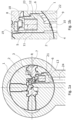
- Figures 1a and 1b show a schematic representation of a first embodiment of a cylinder lock according to the invention
- Figures 2a and 2b show a schematic representation of a first embodiment of a core pin according to the invention
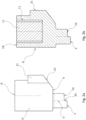
- Figures 3a and 3b show a schematic representation of a second embodiment of a core pin according to the invention
- Figure 4 shows a schematic representation of a spacer plate
- Figures 5a to 5c show a schematic representation of a section of a second embodiment of a cylinder lock according to the invention
- Figs. 1a and 1b show a schematic graphic representation of a first embodiment of a cylinder lock according to the invention, wherein in the Fig. 1b a part of Fig. 1a is shown enlarged.
- the cylinder lock comprises a housing 1 and a cylinder core 2 rotatably mounted therein. According to this illustration, a key 3 is inserted into the key channel 7 of the cylinder lock.
- the key channel 7 extends in a radial plane R through the axis of rotation D of the cylinder core 2 and has a core pin guide 13 in which a core pin 6 is displaceably arranged.
- the core pin guide 13 is arranged approximately normal to the radial plane R and arranged eccentrically to the axis of rotation D with an offset of approximately one third of the cylinder core radius from the axis of rotation D.
- the core pin guide 13 leads laterally and above the axis of rotation D transversely from the housing 1 through the cylinder core 2 into the key channel 7.
- the core pin 6 is shown in its release position. In this release position, the core pin 6 is arranged within the cylinder core 2 without any projection.
- the dividing surface between the cylinder core 2 and the housing 1 is free and a rotation of the cylinder core 2 relative to the housing 1 is possible.
- the core pin 6 can be brought from this release position into its blocking position, whereby rotation of the cylinder core 2 relative to the housing 1 is blocked.
- the core pin 6 comprises a substantially cylindrical base body on which a shoulder 21 is arranged.
- the shoulder 21 is designed to interact with the cylinder core 2, in particular with a stop 23 in the core pin guide 13, so that the movement of the core pin 6 along its longitudinal axis 5 is limited.
- the core pin 6 has a core side 8 and a housing side 9, which lie opposite each other.
- the core side 8 of the core pin 6 points in the direction of the key channel 7 and is designed to query a coding on the key 3.
- the housing side 9 of the core pin 6 points in the direction of the housing 1 and is designed to engage in a housing recess 24.
- the core side 8 of the core pin 6 has first and second control surfaces 18, 19.
- the control surfaces 18, 19 are set up to query a coding, in particular a notch milling, on a side surface of the key 3.
- the first control surface 18 is designed in the form of a web-shaped scanning element which extends over the second control surface 19.
- the control surfaces 18, 19 of the core side 8 of the core pin 6 run essentially normal to the longitudinal axis of the core pin 6 and are essentially flat.
- the housing side 9 of the core pin 6 is designed in a step-shaped manner according to this embodiment.
- the steps of the housing side 9 of the core pin 6 are formed by two locking sections 4, each of which has a locking surface 10 that is essentially normal to the longitudinal axis 5 of the core pin 6.
- a contact surface 22 is provided adjacent to the locking sections 4.
- the housing recess 24 has a smaller cross section than the core pin guide 13, so that the core pin 6 can only penetrate into the housing recess 24 with its locking sections 4, i.e. the locking surfaces 10.
- the further movement of the core pin 6 in the direction of the housing 1 is limited by the fact that the contact surface 22 on the housing side 9 of the core pin 6 abuts against the inner circumference of the housing 1.
- the core pin 6 includes a release device 11, which is designed such that the core pin 6 is moved from the blocking position to the release position when a key 3 assigned to the cylinder lock is inserted into the key channel 7.
- the release device 11 is designed as a permanent magnet, which is arranged in a blind hole 12 on the core side 8 of the core pin 6.
- FIGS. 2a and 2b show schematic representations of an embodiment of a core pin 6 'according to the invention in a side view and a sectional view.
- This core pin 6 ' is a different embodiment than the one in the Figures 1a and 1b shown core pin 6, although their features can preferably correspond.
- the core pin 6' of this embodiment is substantially cylindrical but has a non-circular cross section due to a radially outwardly extending shoulder 21.
- This shoulder 21 serves to limit the movement of the core pin 6' in the core pin guide 13 by being attached to a Stop 23 strikes in the core pin guide 13.
- the core pin 6 has a core side 8 on the end that points in the direction of the key channel 7 and is designed to query a coding on the key and a housing side 9 that points in the direction of the housing 1 and is designed to engage in a housing recess 24.
- the housing side 9 is therefore stepped-shaped, with the locking surfaces 10 forming the steps.
- a short transition area 20 is provided between the blocking surfaces 10.
- the core pin 6 ' comprises a release device 11, which comprises a permanent magnet which is designed to cooperate with a magnetic coding on the key 3.
- the release device 11 is arranged in a blind hole 12 of the core pin 6', which is arranged on the core side 8 of the core pin 6'.
- the blind hole 12 is arranged essentially centrally and along the longitudinal axis 5 of the core pin 6 'and is delimited by an annular section of the core side 8. This annular section forms a first control surface 18.
- FIGS 3a and 3b show schematic representations of a second embodiment of a core pin 6 according to the invention in a side view and in a three-dimensional view.
- This embodiment of the core pin 6 is the one in the Figures 1a and 1b shown core pin 6.
- the core pin 6 is in turn essentially cylindrical with a non-circular cross section due to a shoulder 21 that extends radially outwards.
- the core pin 6 has a core side 8 on the end facing in the direction of the key channel 7 and designed for querying a coding on the key and one in the direction of the housing 1 and designed to engage in a housing recess 24.
- the housing side 9 is therefore stepped-shaped, with the locking surfaces 10 forming the steps.
- a short transition area 20 is provided between the blocking surfaces 10.
- not only the housing side 9, but also the core side 8 is essentially step-shaped.
- first control surface 18 on the core side 8 of the core pin 6, which is flat and runs essentially normal to the longitudinal axis 5 of the core pin 6.
- a second control surface 19 is provided on the core side 8, which is curved along the longitudinal axis 5.
- the first and second control surfaces 18, 19 are arranged concentrically around the blind hole 12, thus forming its boundary or edge.
- the first control surface 18 forms a first circular ring section of the core side 8
- the second control surface 19 forms a second circular ring section of the core side 8.
- the first and second control surfaces 18, 19 are designed to be offset in steps along the longitudinal axis 5.
- the second control surface 19 is formed over an angular range of less than 180° and thus forms a web-shaped scanning pin which is designed to be inserted into a corresponding milling cut on the key 3.
- the Figure 4 shows a schematic representation of a spacer plate 15 according to the invention.
- the spacer plate 15 is essentially cylindrical with a longitudinal axis 25, a front core side 16 and an opposite housing side 17.
- the length of the spacer plate 15 is preferably less than its diameter.
- the core side 16 is essentially stepped-shaped in that at least two blocking surfaces 10 are provided on the core side 16, projecting to different extents along the longitudinal axis 25 and running essentially normal to the longitudinal axis 25 and connected by a transition region 20.
- the transition region 20 between the two steps of the core side 16 preferably runs obliquely to the longitudinal axis 25.
- other shapes of the transition region 20, such as, for example, as part of a circular arc are also provided.
- the housing side 17 can also not be designed in a step-shaped manner, but rather linearly and obliquely to the longitudinal axis 25.
- FIGS. 5a to 5c show schematic representations of a further embodiment of a cylinder lock according to the invention.
- the features of the embodiment according to Figures 5a to 5c can preferably correspond to the features of the embodiments according to Figures 1a, 1b , 2a, 2b , 3a, 3b and/or correspond to 4.
- a housing pin 26 which is preloaded by a spring 14 and interacts with the core pin 6 is provided in the housing recess 24.
- the spring 14 presses the core pin 6 in the direction of the key channel 7.
- the spring 14 is arranged in the housing recess 24.
- the housing pin 26 is designed such that it releases a dividing plane between the cylinder core 2 and the housing 1 when a key 3 assigned to the cylinder lock is inserted into the key channel 7.
- a spacer plate 15 is provided between the housing pin 26 and the core pin 6, the core side 16 of the spacer plate 15 resting on the core pin 6 and the housing side 17 resting on the housing pin 26.
- the core side 16 of the spacer plate 15 is therefore in positive engagement with the housing side 9 of the core pin 6.
- two independent division levels are formed, so that two differently coded keys can lock the lock.
- the spacer plate 15 lies with its core side 16 in a form-fitting manner on the housing side 9 of the core pin 6 and, due to the step-shaped design of these sides, is positively connected to the core pin 6. Due to the positive connection, the spacer plate 15 is guided in the housing recess 24 and can be moved along its longitudinal axis 25 without rotation.
- the core pin 6 is in a position in which the separating surface between the core pin 6 and the spacer plate 15 is aligned with the parting line between the cylinder core 2 and the housing 1, so that the cylinder core 2 can be rotated relative to the housing 1.
- the core pin 6 is in a position in which the housing side 17 of the spacer plate 15 is aligned with the joint between the cylinder core 2 and the housing 1, so that a rotation of the cylinder core 2 relative to the housing 1 is also possible.
- the core pin 6 is in a position in which the housing pin 26 blocks the joint between the cylinder core 2 and the housing 1, so that rotation of the cylinder core 2 relative to the housing 1 is not possible. This configuration can be provided in all embodiments.
- the invention is not limited to the illustrated embodiments, but includes any cylinder lock, any key and any locking device according to the following patent claims.
Description
Die Erfindung betrifft ein Zylinderschloss und eine Schließvorrichtung gemäß den Oberbegriffen der unabhängigen Patentansprüche.The invention relates to a cylinder lock and a locking device according to the preambles of the independent claims.
Aus dem Stand der Technik sind Zylinderschlösser mit einem, in einem Gehäuse um eine Drehachse D drehbaren Zylinderkern, umfassend einen, in einer Radialebene R verlaufenden, Schlüsselkanal zur Einführung eines codierten Schlüssels bekannt. Ferner sind derartige Zylinderschlösser bekannt, bei denen zusätzlich zu den herkömmlichen, in der Radialebene R verlaufenden, Kern- und Gehäusestiften weitere Kernstifte vorgesehen sind, die in einer Kernstiftführung an der Seite des Schlüsselkanals, also außerhalb der Radialebene R, verlaufen. Beispielsweise zeigt die Druckschrift
Nachteilig an derartigen Zylinderschlössern ist jedoch, dass die außerhalb der Radialebene R verlaufenden Kernstifte aufgrund ihrer exzentrischen Positionierung relativ zum Zylinderkern eine weite Distanz verschoben werden müssen, um ausreichend in das Gehäuse zu ragen, damit eine sichere Sperrwirkung eintreten kann. Je weiter der Kernstift von der Drehachse D versetzt ist, umso weiter muss er durch den Schlüssel verschoben werden, um eine ausreichende Erstreckung in das Gehäuse zu gewährleisten. Folglich sind derartige Kernstifte nur mit vergleichsweise großen Stufensprüngen am Schlüssel betätigbar, wodurch die Anzahl der Variationen am Schlüssel gering ist.However, the disadvantage of such cylinder locks is that the core pins running outside the radial plane R have to be moved a long distance due to their eccentric positioning relative to the cylinder core in order to protrude sufficiently into the housing so that a secure locking effect can occur. The further the core pin is offset from the axis of rotation D, the further it must be moved by the key in order to ensure sufficient extension into the housing. Consequently, such core pins can only be actuated with comparatively large increments on the key, which means that the number of variations on the key is small.
Aufgabe der Erfindung ist es, die Nachteile des Standes der Technik zu überwinden. Insbesondere ist es Aufgabe der Erfindung, ein Zylinderschloss zu schaffen, bei welchem schon durch kleine Stufensprünge am Schlüssel eine ausreichende Sperrwirkung realisiert werden kann. Die Aufgabe der Erfindung ist es unterem anderen, ein Zylinderschloss zu schaffen, welches möglichst einfach aufgebaut und kostengünstig herstellbar ist.The object of the invention is to overcome the disadvantages of the prior art. In particular, it is the object of the invention to create a cylinder lock in which a sufficient locking effect can be achieved even through small steps on the key. The object of the invention is, among other things, to create a cylinder lock which is as simple as possible and can be produced inexpensively.
Die erfindungsgemäße Aufgabe wird durch die Merkmale der unabhängigen Patentansprüche gelöst.The object according to the invention is solved by the features of the independent patent claims.
Ein erfindungsgemäßes Zylinderschloss umfasst einen in einem Gehäuse um eine Drehachse D drehbaren Zylinderkern, umfassend einen in einer Radialebene R verlaufenden Schlüsselkanal zur Einführung eines codierten Schlüssels.A cylinder lock according to the invention comprises a cylinder core which can be rotated in a housing about an axis of rotation D, comprising a key channel running in a radial plane R for inserting a coded key.
An einer Seite des Schlüsselkanals ist mindestens eine außerhalb der Radialebene R verlaufende Kernstiftführung vorgesehen. Dabei kann es sich um eine im Wesentlichen zylindrische Bohrung oder dergleichen handeln.At least one core pin guide extending outside the radial plane R is provided on one side of the key channel. This can be a substantially cylindrical bore or the like.
In der Kernstiftführung ist ein Kernstift vorgesehen, der entlang seiner Längsachse in der Kernstiftführung von einer Blockierstellung in eine Freigabestellung verschiebbar ist. Der Kernstift ist derart ausgestaltet, dass die Drehung des Zylinderkerns gegenüber dem Gehäuse freigegeben ist, wenn ein dem Zylinderschloss zugeordneter Schlüssel in den Schlüsselkanal eingeführt ist. Dies kann dadurch erreicht werden, dass zwischen dem Zylinderkern und dem Gehäuse ein im Wesentlichen zylindrischer Spalt (auch als Teilungsebene bezeichnet) gebildet ist, den der Kernstift abhängig von der Codierung des Schlüssels blockiert bzw. freigibt. Der Kernstift kann in der Kernstiftführung durch eine Feder vorgespannt sein; dies ist jedoch nicht zwingend vorgesehen.A core pin is provided in the core pin guide, which can be moved along its longitudinal axis in the core pin guide from a blocking position to a release position. The core pin is designed in such a way that the rotation of the cylinder core relative to the housing is released when a key assigned to the cylinder lock is inserted into the key channel. This can be achieved by forming a substantially cylindrical gap (also referred to as a dividing plane) between the cylinder core and the housing, which the core pin blocks or releases depending on the coding of the key. The core pin can be preloaded in the core pin guide by a spring; However, this is not mandatory.
Der Kernstift ist vorzugsweise von im Wesentlichen zylindrischer Gestalt und umfasst eine in Richtung des Schlüsselkanals weisende und zum Abfragen einer Codierung am Schlüssel ausgebildete Kernseite, sowie eine in Richtung des Gehäuses weisende und zum Eingriff in eine Gehäuseausnehmung ausgebildete Gehäuseseite auf.The core pin is preferably of essentially cylindrical shape and comprises a core side pointing in the direction of the key channel and designed to query a coding on the key, as well as a housing side pointing in the direction of the housing and designed to engage in a housing recess.
Erfindungsgemäß sind an der Gehäuseseite des Kernstifts mindestens zwei in Richtung der Längsachse unterschiedlich weit vorspringende Sperrabschnitte mit jeweils einer im Wesentlichen normal zur Längsachse verlaufenden Sperrfläche vorgesehen. Mit anderen Worten, die Gehäuseseite des Kernstifts ist nicht linear, sondern im Wesentlichen stufenförmig ausgebildet.According to the invention, at least two locking sections projecting to different extents in the direction of the longitudinal axis are provided on the housing side of the core pin, each with a locking surface that runs essentially normal to the longitudinal axis. In other words, the housing side of the core pin is not linear, but essentially step-shaped.
Dadurch wird erreicht, dass - je nach Versatz des Kernstifts und der Kernstiftführung relativ zur Drehachse - die Gehäuseseite derart ausgebildet werden kann, dass bereits eine geringe Verschiebung des Kernstifts zu einer deutlichen Blockierung des Zylinderkerns im Gehäuse führen kann.This ensures that - depending on the offset of the core pin and the core pin guide relative to the axis of rotation - the housing side can be designed in such a way that even a slight displacement of the core pin can lead to a significant blocking of the cylinder core in the housing.
Es ist vorgesehen, dass die Sperrflächen in der Blockierstellung den Zylinderkern überragen. Die Sperrabschnitte ragen in der Blockierstellung des Kernstifts zumindest teilweise, bevorzugt gänzlich, in die Gehäuseausnehmung.It is intended that the blocking surfaces protrude beyond the cylinder core in the blocking position. In the blocking position of the core pin, the locking sections protrude at least partially, preferably completely, into the housing recess.
Die Sperrflächen des Kernstifts sind bevorzugt eben, glatt und/oder erhebungslos. Gegebenenfalls kann zwischen den Sperrabschnitten ein Übergangsbereich angeordnet sein, welcher insbesondere schräg zur Längsachse des Kernstifts verläuft.The locking surfaces of the core pin are preferably flat, smooth and/or without elevations. If necessary, a transition region can be arranged between the locking sections, which in particular runs obliquely to the longitudinal axis of the core pin.
Erfindungsgemäß ist vorgesehen, dass in der Blockierstellung beide Sperrflächen des Kernstifts in die Gehäuseausnehmung ragen, sodass eine Bewegung des Zylinderkerns gegenüber dem Gehäuse verhindert ist, und in der Freigabestellung der Kernstift die Bewegung des Zylinderkerns gegenüber dem Gehäuse freigibt. In der Freigabestellung kann der Kernstift, insbesondere überragungslos und/oder vollständig, im Zylinderkern angeordnet sein.According to the invention it is provided that in the blocking position both locking surfaces of the core pin protrude into the housing recess, so that movement of the cylinder core relative to the housing is prevented, and in the release position the core pin releases the movement of the cylinder core relative to the housing. In the release position, the core pin can be arranged in the cylinder core, in particular without any projection and/or completely.
Im Sinne der Erfindung kann unter dem Begriff, dass eine Seite stufenförmig ausgebildet ist, eine Seite verstanden werden, welche mindestens zwei Stufen umfasst, welche gegebenenfalls durch einen Übergangsbereich beabstandet sind.In the sense of the invention, the term that a side is designed in a step-like manner can be understood as meaning a side which comprises at least two steps, which are optionally spaced apart by a transition region.
Die Kernstiftführung kann sich quer, vorzugsweise normal zur Radialebene R des Zylinderkerns erstrecken und vorzugsweise versetzt zur Drehachse D des Zylinderkerns angeordnet sein.The core pin guide can extend transversely, preferably normal to the radial plane R of the cylinder core and can preferably be arranged offset from the axis of rotation D of the cylinder core.
Der Versatz der Kernstiftführung kann beispielsweise die Hälfte, ein Drittel, ein Viertel oder ein Fünftel des Radius des Zylinderkerns betragen. Durch die stufenförmige Gestaltung der Gehäuseseite des Kernstifts kann der Versatz besonders groß sein und es kann sogar vorgesehen sein, dass zwei oder mehr Kernstifte in einem Quadranten des Zylinderkern-Querschnitts angeordnet sind.The offset of the core pin guide can be, for example, half, a third, a quarter or a fifth of the radius of the cylinder core. Due to the step-shaped design of the housing side of the core pin, the offset can be particularly large and it can even be provided that two or more core pins are arranged in a quadrant of the cylinder core cross section.
Der Kernstift kann im Wesentlichen zylindrisch sein, jedoch einen nicht kreisförmigen Querschnitt aufweisen, sodass er in der Kernstiftführung nicht drehbar ist. Insbesondere kann der Kernstift eine sich abschnittsweise radial nach außen erstreckende Schulter aufweisen, welche dazu ausgebildet ist, mit einem Anschlag in der Kernstiftführung formschlüssig zusammenzuwirken, um die Verschiebung des Kernstifts in der Kernstiftführung in Richtung des Zylinderkerns zu begrenzen.The core pin may be substantially cylindrical but may have a non-circular cross section such that it is not rotatable in the core pin guide. In particular, the core pin can have a shoulder that extends radially outward in sections and is designed to interact positively with a stop in the core pin guide in order to limit the displacement of the core pin in the core pin guide in the direction of the cylinder core.
Um die Bewegung des Kernstifts in der Kernstiftführung in Richtung des Gehäuses zu begrenzen, kann vorgesehen sein, dass die Gehäuseausnehmung einen geringeren Querschnitt aufweist als die Kernstiftführung, sodass der Kernstift nur mit seinen Sperrabschnitten, also den Sperrflächen, in die Gehäuseausnehmung eindringen kann.In order to limit the movement of the core pin in the core pin guide in the direction of the housing, it can be provided that the housing recess has a smaller cross section than the core pin guide, so that the core pin can only penetrate into the housing recess with its locking sections, i.e. the locking surfaces.
Der Kernstift kann eine Freigabevorrichtung umfassen, die derart ausgestaltet ist, dass der Kernstift in der Kernstiftführung von der Blockierstellung in die Freigabestellung verschoben wird, wenn ein dem Zylinderschloss zugeordneter Schlüssel in den Schlüsselkanal eingeführt ist. Die Freigabevorrichtung kann vorzugsweise magnetisierbar sein und besonders bevorzugt einen Permanentmagneten umfassen, der zur Zusammenwirkung mit einer magnetischen Codierung am Schlüssel ausgebildet ist.The core pin can include a release device which is designed such that the core pin in the core pin guide is moved from the blocking position to the release position when a key assigned to the cylinder lock is inserted into the key channel. The release device can preferably be magnetizable and particularly preferably comprise a permanent magnet which is designed to interact with a magnetic coding on the key.
Der Kernstift kann durch das Zusammenwirken mit der Freigabevorrichtung im Wesentlichen in Richtung seiner Längsachse in der Kernstiftführung bewegt werden. Insbesondere können die Freigabevorrichtung und der Kernstift derart zusammenwirken, dass der Kernstift in Richtung des Schlüsselkanals oder in Richtung des Gehäuses bewegt wird, wodurch die Drehung des Zylinderkerns gegenüber dem Gehäuse freigegeben ist.The core pin can be moved essentially in the direction of its longitudinal axis in the core pin guide by interacting with the release device. In particular, the release device and the core pin can cooperate in such a way that the core pin is moved in the direction of the key channel or in the direction of the housing, whereby the rotation of the cylinder core relative to the housing is released.
Die Freigabevorrichtung kann in einer, vorzugsweise als Sackloch ausgebildeten, Ausnehmung des Kernstifts angeordnet sein, die besonders bevorzugt an der Kernseite des Kernstifts, also angrenzend an den Schlüsselkanal, angeordnet ist. Das Sackloch kann vorzugsweise symmetrisch um die Längsachse des Kernstifts gebildet sein.The release device can be arranged in a recess of the core pin, preferably designed as a blind hole, which is particularly preferably arranged on the core side of the core pin, i.e. adjacent to the key channel. The blind hole can preferably be formed symmetrically about the longitudinal axis of the core pin.
An der Kernseite des Kernstifts kann eine erste Steuerfläche vorgesehen sein, die eben ist und im Wesentlichen normal zur Längsachse des Kernstifts verläuft. Ferner kann an der Kernseite des Kernstifts eine zweite Steuerfläche vorgesehen sein, die entlang der Längsachse gebogen oder gewölbt ausgebildet ist.A first control surface can be provided on the core side of the core pin, which is flat and runs essentially normal to the longitudinal axis of the core pin. Furthermore, a second control surface can be provided on the core side of the core pin, which is curved or curved along the longitudinal axis.
Die erste Steuerfläche an der Kernseite des Kernstifts kann einen ersten Kreisringabschnitt bilden. Die zweite Steuerfläche an der Kernseite des Kernstifts kann einen zweiten Kreisringabschnitt bilden. Beide Kreisringabschnitte können den äußeren Umfang der Kernseite des Kernstifts abdecken. Die Steuerflächen können insbesondere konzentrisch um die Ausnehmung, vorzugsweise das Sackloch, angeordnet sein. Die Steuerflächen können vorzugsweise entlang der Längsachse stufenförmig versetzt ausgebildet sein, sodass sich die zweite Steuerfläche weiter in Richtung des Schlüsselkanals erstreckt als die erste Steuerfläche.The first control surface on the core side of the core pin can form a first circular ring section. The second control surface on the core side of the core pin can form a second circular ring section. Both circular ring sections can cover the outer circumference of the core side of the core pin. The control surfaces can in particular be arranged concentrically around the recess, preferably the blind hole. The control surfaces can preferably be designed to be offset in steps along the longitudinal axis, so that the second control surface extends further in the direction of the key channel than the first control surface.
Die zweite Steuerfläche kann insbesondere als stegförmiger Abtastfortsatz zur Abtastung einer schlitzförmigen Codierung am Schlüssel ausgebildet sein. Dadurch kann es möglich sein, die Sicherheit des Zylinderschlosses weiter zu erhöhen, da der Schlüssel einerseits dazu eingerichtet sein muss, den Kernstift zu verschieben, und anderseits eine Codierung aufweisen muss, welche mit der Steuerfläche des Kernstifts zusammenwirken kann. Gegebenenfalls wird der Kernstift nur durch das Zusammenwirken des Schlüssels und der Steuerfläche verschoben.The second control surface can in particular be designed as a web-shaped scanning extension for scanning a slot-shaped coding on the key. This may make it possible to further increase the security of the cylinder lock, since on the one hand the key must be designed to move the core pin and, on the other hand, must have a coding that can interact with the control surface of the core pin. If necessary, the core pin is only moved by the interaction of the key and the control surface.
In der Gehäuseausnehmung kann ein durch eine Feder vorgespannter und mit dem Kernstift zusammenwirkender Gehäusestift vorgesehen sein. Der Gehäusestift kann derart ausgestaltet sein, dass er eine Teilungsebene zwischen dem Zylinderkern und dem Gehäuse bildet und diese freigibt, wenn ein dem Zylinderschloss zugeordneter Schlüssel in den Schlüsselkanal eingeführt ist.A housing pin that is preloaded by a spring and interacts with the core pin can be provided in the housing recess. The housing pin can be designed in such a way that it forms a dividing plane between the cylinder core and the housing and releases this when a key assigned to the cylinder lock is inserted into the key channel.
Zwischen dem Kernstift und dem Gehäusestift kann zumindest ein Distanzplättchen vorgesehen sein, sodass die Drehung des Zylinderkerns gegenüber dem Gehäuse in zwei oder mehr Stellungen des Kernstifts freigegeben ist. Mit anderen Worten ermöglichen die Distanzplättchen die Bildung von zwei oder mehr unabhängigen Teilungsebenen. Dadurch ist es insbesondere möglich, Schlüsselsysteme mit unterschiedlicher Schlüsselhierarchie für die Betätigung des Zylinderschlosses zu verwenden.At least one spacer plate can be provided between the core pin and the housing pin, so that the rotation of the cylinder core relative to the housing is enabled in two or more positions of the core pin. In other words, the spacer plates enable the formation of two or more independent division planes. This makes it possible in particular to use key systems with different key hierarchies for operating the cylinder lock.
Insbesondere ist vorgesehen, dass durch eine Verschiebung des Kernstifts auch das Distanzplättchen verschoben wird. Je nach der Hierarchie des Schlüssels wird der mindestens eine Kernstift, insbesondere dessen Gehäuseseite, oder das mindestens eine Distanzplättchen in eine Position gebracht, in welcher der Zylinderkern gegenüber dem Gehäuse verdrehbar ist.In particular, it is provided that the spacer plate is also displaced by a displacement of the core pin. Depending on the hierarchy of the key, the at least one core pin, in particular its housing side, or the at least one spacer plate is brought into a position in which the cylinder core can be rotated relative to the housing.
Bevorzugt fluchtet die Gehäuseseite des mindestens einen Kernstifts, die Gehäuseseite des mindestens einen Distanzplättchens oder die Trennfläche zwischen dem mindestens einen Kernstift und dem mindestens einen Distanzplättchen mit der Trennfuge (Teilungsebene) zwischen Zylinderkern und Gehäuse, sodass gegebenenfalls eine Verdrehung des Zylinderkerns gegenüber dem Gehäuse möglich ist.The housing side of the at least one core pin, the housing side of the at least one spacer plate or the separating surface between the at least one core pin and the at least one spacer plate are preferably aligned with the parting line (partition plane) between the cylinder core and the housing, so that a rotation of the cylinder core relative to the housing is possible if necessary .
Erfindungsgemäß kann vorgesehen sein, dass das Distanzplättchen im Wesentlichen zylindrisch mit einer Längsachse, einer stirnseitigen Kernseite und einer gegenüberliegenden Gehäuseseite ausgebildet ist. Die Kernseite kann am Kernstift und die Gehäuseseite am Gehäusestift oder an einem weiteren Distanzplättchen anliegen. Die Kernseite kann mit der Gehäuseseite des Kernstifts formschlüssig in Eingriff stehen. Dabei kann die Kernseite vorzugsweise im Wesentlichen stufenförmig ausgebildet sein, indem an der Kernseite zumindest zwei entlang der Längsachse unterschiedlich weit vorspringende, im Wesentlichen normal zur Längsachse verlaufende, gegebenenfalls durch einen Übergangsbereich verbundene Sperrflächen vorgesehen sind.According to the invention, it can be provided that the spacer plate is essentially cylindrical with a longitudinal axis, a front core side and an opposite housing side. The core side can rest on the core pin and the housing side on the housing pin or on another spacer plate. The core side can be in positive engagement with the housing side of the core pin. The core side can preferably be designed essentially step-shaped, in that at least two blocking surfaces are provided on the core side, projecting to different extents along the longitudinal axis and running essentially normal to the longitudinal axis, optionally connected by a transition region.
Mindestens eine Sperrfläche des mindestens einen Distanzplättchens kann bevorzugt eben, glatt und/oder erhebungslos ausgebildet sein. Die Stufen der Kernseite des Distanzplättchens können durch die mindestens zwei Sperrflächen gebildet sein. Zwischen den mindestens zwei Sperrflächen der Kernseite des Distanzplättchens kann ein Übergangsbereich angeordnet sein, welcher insbesondere schräg zur Längsachse des Distanzplättchens verläuft.At least one blocking surface of the at least one spacer plate can preferably be flat, smooth and/or raised-free. The steps on the core side of the spacer plate can be formed by the at least two blocking surfaces. A transition region can be arranged between the at least two blocking surfaces on the core side of the spacer plate, which in particular runs obliquely to the longitudinal axis of the spacer plate.
Bevorzugt ist das Distanzplättchen, insbesondere dessen Kern- und/oder Gehäuseseite, derart ausgebildet, dass das Distanzplättchen, insbesondere mit dem Kernstift, insbesondere mit der Gehäuseseite des Kernstifts, und/oder einem weiteren Distanzplättchen formschlüssig verbindbar ist.The spacer plate, in particular its core and/or housing side, is preferably designed in such a way that the spacer plate can be positively connected, in particular to the core pin, in particular to the housing side of the core pin, and/or another spacer plate.
Die Kernseite des Distanzplättchens kann im Wesentlichen der Gehäuseseite des Kernstifts entsprechen. Die Gehäuseseite des Distanzplättchens kann im Wesentlichen der Kernseite eines weiteren Distanzplättchens entsprechen. Die Gehäuseseite des Distanzplättchens kann aber auch nicht stufenförmig, sondern gebogen, schräg oder abgerundet sein.The core side of the spacer plate can essentially correspond to the housing side of the core pin. The housing side of the spacer plate can essentially correspond to the core side of another spacer plate. The housing side of the spacer plate can also not be step-shaped, but bent, slanted or rounded.
Durch die formschlüssige Verbindung kann das Distanzplättchen gemeinsam mit dem Kernstift geführt werden. Dadurch kann erreicht werden, dass das Distanzplättchen unverdrehbar in Richtung seiner Längsachse bewegbar ist.Thanks to the positive connection, the spacer plate can be guided together with the core pin. This makes it possible for the spacer plate to be non-rotatably movable in the direction of its longitudinal axis.
Selbstverständlich kann das Zylinderschloss auch weitere Abfrageelemente zur Abfrage beliebiger Codierungen am Schlüssel aufweisen.Of course, the cylinder lock can also have further query elements for querying any coding on the key.
Ferner offenbart wird ein Schlüssel für ein erfindungsgemäßes Zylinderschloss, wobei der Schlüssel mindestens eine vorzugsweise magnetische Codierung aufweist, die derart ausgestaltet ist, dass der Kernstift von der Blockierstellung in die Freigabestellung verschoben wird, wenn der Schlüssel in den Schlüsselkanal eingeführt ist. Selbstverständlich kann der Schlüssel auch weitere Codierungen aufweisen.Also disclosed is a key for a cylinder lock according to the invention, wherein the key has at least one preferably magnetic coding which is designed such that the core pin is moved from the blocking position to the release position when the key is inserted into the key channel. Of course, the key can also have other codings.
Die Erfindung betrifft ferner eine Schließvorrichtung mit einem erfindungsgemäßen Zylinderschloss und einem derartigen Schlüssel.The invention further relates to a locking device with a cylinder lock according to the invention and such a key.
Der Umfang dieser Erfindung wird durch die vorliegenden Patentansprüche definiert.The scope of this invention is defined by the present claims.
Die Erfindung wird nun am Beispiel exemplarischer, nicht ausschließlicher und/oder nicht einschränkender Ausführungsbeispiele weiter erläutert.The invention will now be further explained using exemplary, non-exclusive and/or non-limiting exemplary embodiments.
Der Schlüsselkanal 7 erstreckt sich in einer Radialebene R durch die Drehachse D des Zylinderkerns 2 und weist eine Kernstiftführung 13 auf, in welcher ein Kernstift 6 verschiebbar angeordnet ist. Die Kernstiftführung 13 ist etwa normal zur Radialebene R angeordnet und exzentrisch zur Drehachse D mit einem Versatz von etwa einem Drittel des Zylinderkernradius von der Drehachse D angeordnet. Mit anderen Worten, die Kernstiftführung 13 führt seitlich und oberhalb der Drehachse D quer vom Gehäuse 1 durch den Zylinderkern 2 in den Schlüsselkanal 7.The
In dieser Darstellung ist der Kernstift 6 in seiner Freigabestellung dargestellt. In dieser Freigabestellung ist der Kernstift 6 überragungslos innerhalb des Zylinderkerns 2 angeordnet.In this illustration, the
Dadurch ist in der Freigabestellung die Teilungsfläche zwischen Zylinderkern 2 und Gehäuse 1 frei und eine Drehung des Zylinderkerns 2 gegenüber dem Gehäuse 1 ist möglich. Der Kernstift 6 kann von dieser Freigabestellung in seine Blockierstellung gebracht werden, wodurch eine Drehung des Zylinderkerns 2 gegenüber dem Gehäuse 1 blockiert ist.As a result, in the release position, the dividing surface between the
Der Kernstift 6 umfasst gemäß dieser Ausführungsform einen im Wesentlichen zylindrischen Grundkörper an welchem eine Schulter 21 angeordnet ist. Die Schulter 21 ist dazu eingerichtet mit dem Zylinderkern 2, insbesondere mit einem Anschlag 23 in der Kernstiftführung 13, zusammenzuwirken, sodass die Bewegung des Kernstiftes 6 entlang seiner Längsachse 5 begrenzt ist.According to this embodiment, the
Gemäß dieser Ausführungsform weist der Kernstift 6 eine Kernseite 8 und eine Gehäuseseite 9 auf, welche einander gegenüberliegen. Die Kernseite 8 des Kernstifts 6 weist in Richtung des Schlüsselkanals 7 und ist zum Abfragen einer Codierung am Schlüssel 3 ausgebildet. Die Gehäuseseite 9 des Kernstifts 6 weist in Richtung des Gehäuses 1 und ist zum Eingriff in eine Gehäuseausnehmung 24 ausgebildet.According to this embodiment, the
Die Kernseite 8 des Kernstifts 6 weist gemäß dieser Ausführungsform erste und zweite Steuerflächen 18, 19 auf. Die Steuerflächen 18, 19 sind dazu eingerichtet, eine Codierung, insbesondere eine Einschnittfräsung, an einer Seitenfläche des Schlüssels 3 abzufragen. Die erste Steuerfläche 18 ist in Form eines stegförmigen Abtastelements ausgebildet, welches sich über die zweite Steuerfläche 19 erstreckt. Die Steuerflächen 18, 19 der Kernseite 8 des Kernstifts 6 verlaufen im Wesentlichen normal zu der Längsachse des Kernstifts 6 und sind im Wesentlichen eben ausgebildet.According to this embodiment, the
Die Gehäuseseite 9 des Kernstiftes 6 ist gemäß dieser Ausführungsform stufenförmig ausgebildet. Die Stufen der Gehäuseseite 9 des Kernstifts 6 sind durch zwei Sperrabschnitte 4 gebildet, welche jeweils eine im Wesentlichen normal auf die Längsachse 5 des Kernstifts 6 stehende Sperrfläche 10 aufweisen. Angrenzend an die Sperrabschnitte 4 ist eine Kontaktfläche 22 vorgesehen.The
Die Gehäuseausnehmung 24 weist einen geringeren Querschnitt auf als die Kernstiftführung 13, sodass der Kernstift 6 nur mit seinen Sperrabschnitten 4, also den Sperrflächen 10, in die Gehäuseausnehmung 24 eindringen kann. Die weitere Bewegung des Kernstifts 6 in Richtung des Gehäuses 1 wird dadurch begrenzt, dass die Kontaktfläche 22 an der Gehäuseseite 9 des Kernstifts 6 gegen den inneren Umfang des Gehäuses 1 stößt.The
Der Kernstift 6 umfasst eine Freigabevorrichtung 11, welche derart ausgestaltet ist, dass der Kernstift 6 von der Blockierstellung in die Freigabestellung bewegt wird, wenn ein dem Zylinderschloss zugeordneter Schlüssel 3 in den Schlüsselkanal 7 eingeführt ist. Gemäß dieser Ausführungsform ist die Freigabevorrichtung 11 als Permanentmagnet ausgebildet, welcher in einem Sackloch 12 an der Kernseite 8 des Kernstifts 6 angeordnet ist.The
Die
Der Kernstift 6' dieser Ausführungsform ist im Wesentlichen zylindrisch, hat jedoch einen nicht kreisförmigen Querschnitt aufgrund einer sich radial nach außen erstreckenden Schulter 21. Diese Schulter 21 dient dazu, die Bewegung des Kernstifts 6' in der Kernstiftführung 13 zu begrenzen, indem sie an einem Anschlag 23 in der Kernstiftführung 13 anschlägt.The core pin 6' of this embodiment is substantially cylindrical but has a non-circular cross section due to a radially outwardly extending
Der Kernstift 6' hat jeweils stirnseitig eine in Richtung des Schlüsselkanals 7 weisende und zum Abfragen einer Codierung am Schlüssel ausgebildete Kernseite 8 und eine in Richtung des Gehäuses 1 weisende und zum Eingriff in eine Gehäuseausnehmung 24 ausgebildete Gehäuseseite 9. An der Gehäuseseite 9 sind zwei in Richtung der Längsachse 5 unterschiedlich weit vorspringende Sperrabschnitte 4 vorgesehen, die jeweils eine im Wesentlichen normal zur Längsachse 5 verlaufende Sperrfläche 10 aufweisen.The core pin 6 'has a
Die Gehäuseseite 9 ist also stufenförmig ausgebildet, wobei die Sperrflächen 10 die Stufen bilden. Zwischen den Sperrflächen 10 ist ein kurzer Übergangsbereich 20 vorgesehen.The
Der Kernstift 6' umfasst eine Freigabevorrichtung 11, die einen Permanentmagneten umfasst, der zur Zusammenwirkung mit einer magnetischen Codierung am Schlüssel 3 ausgebildet ist. Die Freigabevorrichtung 11 ist in einem Sackloch 12 des Kernstifts 6' angeordnet, das an der Kernseite 8 des Kernstifts 6' angeordnet ist. Das Sackloch 12 ist im Wesentlichen zentral und entlang der Längsachse 5 des Kernstifts 6' angeordnet und von einem kreisringförmigen Abschnitt der Kernseite 8 begrenzt. Dieser kreisringförmige Abschnitt bildet eine erste Steuerfläche 18.The core pin 6 'comprises a
Die
Der Kernstift 6 ist wiederum im Wesentlichen zylindrisch mit einem nicht kreisförmigen Querschnitt aufgrund einer sich radial nach außen erstreckenden Schulter 21. Der Kernstift 6 hat jeweils stirnseitig eine in Richtung des Schlüsselkanals 7 weisende und zum Abfragen einer Codierung am Schlüssel ausgebildete Kernseite 8 und eine in Richtung des Gehäuses 1 weisende und zum Eingriff in eine Gehäuseausnehmung 24 ausgebildete Gehäuseseite 9. An der Gehäuseseite 9 sind zwei in Richtung der Längsachse 5 unterschiedlich weit vorspringende Sperrabschnitte 4 vorgesehen, die jeweils eine im Wesentlichen normal zur Längsachse 5 verlaufende Sperrfläche 10 aufweisen. Die Gehäuseseite 9 ist also stufenförmig ausgebildet, wobei die Sperrflächen 10 die Stufen bilden. Zwischen den Sperrflächen 10 ist ein kurzer Übergangsbereich 20 vorgesehen.The
Im Unterschied zur Ausführung gemäß
Dies wird erreicht, indem an der Kernseite 8 des Kernstifts 6 eine erste Steuerfläche 18 vorgesehen ist, die eben ist und im Wesentlichen normal zur Längsachse 5 des Kernstifts 6 verläuft. Außerdem ist an der Kernseite 8 eine zweite Steuerfläche 19 vorgesehen, die entlang der Längsachse 5 gebogen ausgebildet ist. Die erste und zweite Steuerfläche 18, 19 sind konzentrisch um das Sackloch 12 angeordnet, bilden also dessen Begrenzung bzw. Rand. Die erste Steuerfläche 18 bildet einen ersten Kreisringabschnitt der Kernseite 8, und die zweite Steuerfläche 19 bildet einen zweiten Kreisringabschnitt der Kernseite 8. Die erste und zweite Steuerfläche 18, 19 sind entlang der Längsachse 5 stufenförmig versetzt ausgebildet. Die zweite Steuerfläche 19 ist in diesem Ausführungsbeispiel über einen Winkelbereich von unter 180° ausgebildet und bildet somit einen stegförmigen Abtastzapfen, der zum Einführen in eine entsprechende Einschnittfräsung am Schlüssel 3 ausgebildet ist.This is achieved by providing a
Die
Die
In dieser Ausführungsform ist in der Gehäuseausnehmung 24 ein durch eine Feder 14 vorgespannter und mit dem Kernstift 6 zusammenwirkender Gehäusestift 26 vorgesehen. Die Feder 14 drückt den Kernstift 6 in Richtung des Schlüsselkanals 7. Die Feder 14 ist in der Gehäuseausnehmung 24 angeordnet. Der Gehäusestift 26 ist derart ausgestaltet, dass er eine Teilungsebene zwischen dem Zylinderkern 2 und dem Gehäuse 1 freigibt, wenn ein dem Zylinderschloss zugeordneter Schlüssel 3 in den Schlüsselkanal 7 eingeführt ist.In this embodiment, a
Zwischen dem Gehäusestift 26 und dem Kernstift 6 ist ein Distanzplättchen 15 vorgesehen, wobei die Kernseite 16 des Distanzplättchens 15 am Kernstift 6, und die Gehäuseseite 17 am Gehäusestift 26 anliegt. Die Kernseite 16 des Distanzplättchens 15 steht also mit der Gehäuseseite 9 des Kernstifts 6 formschlüssig in Eingriff. Dadurch sind in dieser Ausführungsform zwei unabhängige Teilungsebenen gebildet, sodass zwei unterschiedlich codierte Schlüssel das Schloss sperren können.A
Das Distanzplättchen 15 liegt gemäß dieser Ausführungsform mit seiner Kernseite 16 formschlüssig an der Gehäuseseite 9 des Kernstifts 6 an und ist, aufgrund der stufenförmigen Ausbildung dieser Seiten, mit dem Kernstift 6 formschlüssig verbunden. Durch die formschlüssige Verbindung ist das Distanzplättchen 15 in der Gehäuseausnehmung 24 geführt und ist verdrehungsfrei entlang seiner Längsachse 25 bewegbar.According to this embodiment, the
In der
Die Erfindung beschränkt sich nicht auf die dargestellten Ausführungsformen, sondern umfasst jegliches Zylinderschloss, jeglichen Schlüssel und jegliche Schließvorrichtung gemäß den nachfolgenden Patentansprüchen.The invention is not limited to the illustrated embodiments, but includes any cylinder lock, any key and any locking device according to the following patent claims.
- 11
- GehäuseHousing
- 22
- ZylinderkernCylinder core
- 33
- SchlüsselKey
- 44
- SperrabschnittBarrier section
- 55
- Längsachse des KernstiftsLongitudinal axis of the core pin
- 6, 6'6, 6'
- Kernstiftcore pin
- 77
- SchlüsselkanalKey channel
- 88th
- Kernseite des KernstiftsCore side of the core pin
- 99
- Gehäuseseite des KernstiftsHousing side of the core pin
- 1010
- Sperrflächerestricted area
- 1111
- FreigabevorrichtungRelease device
- 1212
- Sacklochblind hole
- 1313
- KernstiftführungCore pin guide
- 1414
- FederFeather
- 1515
- DistanzplättchenSpacer plates
- 1616
- Kernseite des DistanzplättchensCore side of the spacer plate
- 1717
- Gehäuseseite des DistanzplättchensHousing side of the spacer plate
- 1818
- Erste SteuerflächeFirst control surface
- 1919
- Zweite SteuerflächeSecond control surface
- 2020
- ÜbergangsbereichTransition area
- 2121
- Schultershoulder
- 2222
- Kontaktfläche der Gehäuseseite des KernstiftsContact surface of the housing side of the core pin
- 2323
- Anschlagattack
- 2424
- GehäuseausnehmungHousing recess
- 2525
- Längsachse des DistanzplättchensLongitudinal axis of the spacer plate
- 2626
- GehäusestiftHousing pin
Claims (15)
- A cylinder lock with a cylinder core (2) rotatable in a housing (1) about an axis of rotation D, comprising a key channel (7) extending in a radial plane R for the insertion of an encoded key (3),- wherein at least one core pin guide (13) extending outside the radial plane R is provided on one side of the key channel (7),- wherein a core pin (6, 6') is provided in the core pin guide (13), whichcharacterised in that∘ is displaceable along its longitudinal axis (5) in the core pin guide (13) from a locking position into a release position,∘ has a core side (8) facing in the direction of the key channel (7) and designed for interrogating a code on the key,∘ has a housing side (9) facing in the direction of the housing (1) and designed for engaging in a housing recess (24), and∘ is designed in such a way that the rotation of the cylinder core (2) relative to the housing (1) is released when a key (3) associated with the cylinder lock is inserted into the key channel (7),
at least two locking sections (4) projecting to different extents in the direction of the longitudinal axis (5) are provided on the housing side (9), each with a locking surface (10) extending substantially normal to the longitudinal axis (5), so that the housing side (9) is substantially formed step-shaped, wherein in the locking position both locking surfaces (10) of the core pin (6, 6') project into the housing recess (24) so that a movement of the cylinder core (2) relative to the housing (1) is prevented, and in the release position the core pin (6, 6') releases the movement of the cylinder core (2) relative to the housing (1). - The cylinder lock according to claim 1, characterised in that the core pin guide (13) extends transversely, preferably perpendicularly to the radial plane R of the cylinder core (2) and is preferably arranged offset to the axis of rotation D of the cylinder core (2).
- The cylinder lock according to claim 1 or 2, characterised in that the core pin (6, 6') has a non-circular cross-section and is not rotatable in the core pin guide (13).
- The cylinder lock according to one of claims 1 to 3, characterised in that the core pin (6, 6') comprises a release device (11) which is designed in such a way that the core pin (6, 6') is displaced in the core pin guide (13) from the locking position into the release position, when a key (3) associated with the cylinder lock is inserted into the key channel (7), wherein the release device (11) is preferably magnetisable and particularly preferably comprises a permanent magnet which is designed to cooperate with a magnetic code on the key (3).
- The cylinder lock according to claim 4, characterised in that the release device (11) is arranged in a recess of the core pin (6, 6') which is preferably designed as a blind hole (12) and which is particularly preferably arranged on the core side (8) of the core pin (6, 6').
- The cylinder lock according to one of claims 1 to 5, characterised in that a first control surface (18) is provided on the core side (8) of the core pin (6, 6'), which control surface is flat and extends substantially normal to the longitudinal axis (5) of the core pin (6, 6').
- The cylinder lock according to one of claims 1 to 6, characterised in that a second control surface (19) is provided on the core side (8) of the core pin (6, 6'), which control surface is curved along the longitudinal axis (5).
- The cylinder lock according to claim 7 in combination with claim 6, characterised in that the first control surface (18) forms a first annular portion of the core side (8), and the second control surface (19) forms a second annular portion of the core side (8), wherein the control surfaces (18, 19) are step-shaped and offset along the longitudinal axis (5).
- The cylinder lock according to claim 8 in combination with claim 5, characterised in that the control surfaces (18, 19) are arranged concentrically around the recess, preferably the blind hole (12).
- The cylinder lock according to one of claims 1 to 9, characterised in that the core pin (6, 6') has a substantially cylindrical cross-section with a shoulder (21) which extends radially outwards in sections and is designed to cooperate in a form-fitting manner with a stop (23) in the core pin guide (13) in order to limit the displacement of the core pin (6, 6') in the core pin guide (13).
- The cylinder lock according to one of claims 1 to 10, characterised in that a housing pin (26) is provided in the housing recess (24), which pin is preloaded by a spring (14) and cooperates with the core pin (6, 6') and is designed in such a way that it releases a dividing plane between the cylinder core (2) and the housing (1) when a key (3) associated with the cylinder lock is inserted into the key channel (7).
- The cylinder lock according to claim 11, characterised in that at least one spacer plate (15) is provided between the core pin (6, 6') and the housing pin (26), so that rotation of the cylinder core (2) relative to the housing (1) is released in two or more positions of the core pin (6, 6').
- The cylinder lock according to claim 12, characterised in thata. the spacer plate (15) is substantially cylindrical with a longitudinal axis (25), a core side (16) and a housing side (17),b. wherein the core side (16) rests against the core pin (6, 6') and the housing side (17) rests against the housing pin (26) or against a further spacer plate (15),c. wherein the core side (16) is in positive engagement with the housing side (9) of the core pin (6, 6'), and wherein, preferably,d. the core side (16) is substantially step-shaped, in that at least two locking surfaces (10) are provided on the core side (16), which surfaces project to different extents along the longitudinal axis (25), run substantially normal to the longitudinal axis (25) and are optionally connected by a transition region (20).
- The cylinder lock according to claim 13, characterised in that the housing side (17) of the spacer plate (15) is not step-shaped, but curved, oblique or rounded.
- A locking device with a cylinder lock according to one of claims 1 to 14 and a key (3), characterised in that the key (3) has at least one preferably magnetic code which is designed in such a way that the core pin (6, 6') is displaced from the locking position into the release position when the key (3) is inserted into the key channel (7).
Applications Claiming Priority (2)
| Application Number | Priority Date | Filing Date | Title |
|---|---|---|---|
| ATA50336/2020A AT523709B1 (en) | 2020-04-20 | 2020-04-20 | Cylinder lock, key and locking device |
| PCT/EP2021/059428 WO2021213829A1 (en) | 2020-04-20 | 2021-04-12 | Cylinder lock, key and locking device |
Publications (2)
| Publication Number | Publication Date |
|---|---|
| EP4045743A1 EP4045743A1 (en) | 2022-08-24 |
| EP4045743B1 true EP4045743B1 (en) | 2023-11-01 |
Family
ID=75581493
Family Applications (1)
| Application Number | Title | Priority Date | Filing Date |
|---|---|---|---|
| EP21719866.2A Active EP4045743B1 (en) | 2020-04-20 | 2021-04-12 | Cylinder lock and locking device |
Country Status (3)
| Country | Link |
|---|---|
| EP (1) | EP4045743B1 (en) |
| AT (1) | AT523709B1 (en) |
| WO (1) | WO2021213829A1 (en) |
Family Cites Families (7)
| Publication number | Priority date | Publication date | Assignee | Title |
|---|---|---|---|---|
| DE4205643C2 (en) * | 1992-02-25 | 1994-10-13 | Wilka Schliestechnik Gmbh | Profile cylinder |
| DE29507953U1 (en) * | 1994-09-29 | 1995-07-27 | Evva Werke | Flat key and cylinder lock |
| DE19654136C2 (en) * | 1996-12-23 | 1999-11-18 | Schulte C E Gmbh | Locking cylinder |
| US5823029A (en) * | 1997-01-29 | 1998-10-20 | International Security Products, Inc. | Cylinder lock system |
| US5819566A (en) * | 1997-01-29 | 1998-10-13 | International Security Products, Inc. | Cylinder lock and key |
| DE102010012261B4 (en) * | 2010-03-22 | 2015-08-20 | Abus Pfaffenhain Gmbh | locking system |
| DE102013114423B4 (en) | 2013-12-19 | 2023-05-17 | M. van der Wal Holding B. V. | Lock cylinder with magnetic tumbler pin |
-
2020
- 2020-04-20 AT ATA50336/2020A patent/AT523709B1/en active
-
2021
- 2021-04-12 WO PCT/EP2021/059428 patent/WO2021213829A1/en unknown
- 2021-04-12 EP EP21719866.2A patent/EP4045743B1/en active Active
Also Published As
| Publication number | Publication date |
|---|---|
| AT523709A4 (en) | 2021-11-15 |
| AT523709B1 (en) | 2021-11-15 |
| WO2021213829A1 (en) | 2021-10-28 |
| EP4045743A1 (en) | 2022-08-24 |
Similar Documents
| Publication | Publication Date | Title |
|---|---|---|
| EP2314807B1 (en) | Locking system | |
| EP2603654B1 (en) | Lock device | |
| EP3061893B1 (en) | Key for a lock cylinder and locking device | |
| EP3814590B1 (en) | Flat key for cylinder lock and cylinder lock | |
| EP3155191B1 (en) | Cylinder lock | |
| EP3922788A1 (en) | Key blank and key for actuating a cutting cylinder, and method for manufacturing such a key blank and key | |
| EP4045743B1 (en) | Cylinder lock and locking device | |
| DE102013103790B4 (en) | lock cylinder | |
| EP3092359B1 (en) | Cylinder lock | |
| DE102010012261B4 (en) | locking system | |
| EP2844811A1 (en) | Key and rotary cylinder lock with key | |
| EP3205796B1 (en) | Key for a lock cylinder, lock cylinder and locking device | |
| AT403607B (en) | LOCKING DEVICE WITH A CYLINDLE LOCK AND A REVERSIBLE FLAT KEY | |
| EP3483365B1 (en) | Key for operating a lock cylinder and locking system with key and lock cylinder | |
| EP3280854B1 (en) | Key, key blank and lock system with such a key and a corresponding lock cylinder | |
| EP3812537B1 (en) | Locking cylinder | |
| DE2558249A1 (en) | Permanent magnet operated cylinder lock - has bolt locking element with extensions fitting into corresponding core recesses | |
| DE2930425A1 (en) | CYLINDLE LOCK | |
| DE2806072A1 (en) | Key and combination lock with axial tumbler pins - have additional transversely offset stop faces to activate different pins | |
| DE202006020501U1 (en) | Cylinder lock with protection against manipulation by impact | |
| WO2015000966A1 (en) | Key and rotary lock cylinder |
Legal Events
| Date | Code | Title | Description |
|---|---|---|---|
| STAA | Information on the status of an ep patent application or granted ep patent |
Free format text: STATUS: UNKNOWN |
|
| STAA | Information on the status of an ep patent application or granted ep patent |
Free format text: STATUS: THE INTERNATIONAL PUBLICATION HAS BEEN MADE |
|
| PUAI | Public reference made under article 153(3) epc to a published international application that has entered the european phase |
Free format text: ORIGINAL CODE: 0009012 |
|
| STAA | Information on the status of an ep patent application or granted ep patent |
Free format text: STATUS: REQUEST FOR EXAMINATION WAS MADE |
|
| 17P | Request for examination filed |
Effective date: 20220519 |
|
| AK | Designated contracting states |
Kind code of ref document: A1 Designated state(s): AL AT BE BG CH CY CZ DE DK EE ES FI FR GB GR HR HU IE IS IT LI LT LU LV MC MK MT NL NO PL PT RO RS SE SI SK SM TR |
|
| P01 | Opt-out of the competence of the unified patent court (upc) registered |
Effective date: 20230509 |
|
| DAV | Request for validation of the european patent (deleted) | ||
| DAX | Request for extension of the european patent (deleted) | ||
| GRAP | Despatch of communication of intention to grant a patent |
Free format text: ORIGINAL CODE: EPIDOSNIGR1 |
|
| STAA | Information on the status of an ep patent application or granted ep patent |
Free format text: STATUS: GRANT OF PATENT IS INTENDED |
|
| INTG | Intention to grant announced |
Effective date: 20230629 |
|
| GRAS | Grant fee paid |
Free format text: ORIGINAL CODE: EPIDOSNIGR3 |
|
| GRAA | (expected) grant |
Free format text: ORIGINAL CODE: 0009210 |
|
| STAA | Information on the status of an ep patent application or granted ep patent |
Free format text: STATUS: THE PATENT HAS BEEN GRANTED |
|
| AK | Designated contracting states |
Kind code of ref document: B1 Designated state(s): AL AT BE BG CH CY CZ DE DK EE ES FI FR GB GR HR HU IE IS IT LI LT LU LV MC MK MT NL NO PL PT RO RS SE SI SK SM TR |
|
| REG | Reference to a national code |
Ref country code: GB Ref legal event code: FG4D Free format text: NOT ENGLISH |
|
| REG | Reference to a national code |
Ref country code: CH Ref legal event code: EP |
|
| REG | Reference to a national code |
Ref country code: DE Ref legal event code: R096 Ref document number: 502021001868 Country of ref document: DE |
|
| REG | Reference to a national code |
Ref country code: IE Ref legal event code: FG4D Free format text: LANGUAGE OF EP DOCUMENT: GERMAN |
|
| REG | Reference to a national code |
Ref country code: NL Ref legal event code: FP |
|
| REG | Reference to a national code |
Ref country code: SE Ref legal event code: TRGR |
|
| REG | Reference to a national code |
Ref country code: LT Ref legal event code: MG9D |
|
| PG25 | Lapsed in a contracting state [announced via postgrant information from national office to epo] |
Ref country code: GR Free format text: LAPSE BECAUSE OF FAILURE TO SUBMIT A TRANSLATION OF THE DESCRIPTION OR TO PAY THE FEE WITHIN THE PRESCRIBED TIME-LIMIT Effective date: 20240202 |
|
| PG25 | Lapsed in a contracting state [announced via postgrant information from national office to epo] |
Ref country code: IS Free format text: LAPSE BECAUSE OF FAILURE TO SUBMIT A TRANSLATION OF THE DESCRIPTION OR TO PAY THE FEE WITHIN THE PRESCRIBED TIME-LIMIT Effective date: 20240301 |
|
| PG25 | Lapsed in a contracting state [announced via postgrant information from national office to epo] |
Ref country code: LT Free format text: LAPSE BECAUSE OF FAILURE TO SUBMIT A TRANSLATION OF THE DESCRIPTION OR TO PAY THE FEE WITHIN THE PRESCRIBED TIME-LIMIT Effective date: 20231101 |