EP4045356B1 - Fluggastsitz und sitzreihe - Google Patents
Fluggastsitz und sitzreihe Download PDFInfo
- Publication number
- EP4045356B1 EP4045356B1 EP21714100.1A EP21714100A EP4045356B1 EP 4045356 B1 EP4045356 B1 EP 4045356B1 EP 21714100 A EP21714100 A EP 21714100A EP 4045356 B1 EP4045356 B1 EP 4045356B1
- Authority
- EP
- European Patent Office
- Prior art keywords
- table top
- passenger seat
- adjustment means
- aircraft passenger
- component
- Prior art date
- Legal status (The legal status is an assumption and is not a legal conclusion. Google has not performed a legal analysis and makes no representation as to the accuracy of the status listed.)
- Active
Links
Images


Classifications
-
- B—PERFORMING OPERATIONS; TRANSPORTING
- B64—AIRCRAFT; AVIATION; COSMONAUTICS
- B64D—EQUIPMENT FOR FITTING IN OR TO AIRCRAFT; FLIGHT SUITS; PARACHUTES; ARRANGEMENT OR MOUNTING OF POWER PLANTS OR PROPULSION TRANSMISSIONS IN AIRCRAFT
- B64D11/00—Passenger or crew accommodation; Flight-deck installations not otherwise provided for
- B64D11/06—Arrangements of seats, or adaptations or details specially adapted for aircraft seats
- B64D11/0648—Lower frame constructions
-
- B—PERFORMING OPERATIONS; TRANSPORTING
- B60—VEHICLES IN GENERAL
- B60N—SEATS SPECIALLY ADAPTED FOR VEHICLES; VEHICLE PASSENGER ACCOMMODATION NOT OTHERWISE PROVIDED FOR
- B60N3/00—Arrangements or adaptations of other passenger fittings, not otherwise provided for
- B60N3/001—Arrangements or adaptations of other passenger fittings, not otherwise provided for of tables or trays
- B60N3/002—Arrangements or adaptations of other passenger fittings, not otherwise provided for of tables or trays of trays
- B60N3/004—Arrangements or adaptations of other passenger fittings, not otherwise provided for of tables or trays of trays of foldable trays mounted on the back-rest
-
- B—PERFORMING OPERATIONS; TRANSPORTING
- B64—AIRCRAFT; AVIATION; COSMONAUTICS
- B64D—EQUIPMENT FOR FITTING IN OR TO AIRCRAFT; FLIGHT SUITS; PARACHUTES; ARRANGEMENT OR MOUNTING OF POWER PLANTS OR PROPULSION TRANSMISSIONS IN AIRCRAFT
- B64D11/00—Passenger or crew accommodation; Flight-deck installations not otherwise provided for
- B64D11/06—Arrangements of seats, or adaptations or details specially adapted for aircraft seats
- B64D11/0638—Arrangements of seats, or adaptations or details specially adapted for aircraft seats with foldable tables, trays or cup holders
-
- B—PERFORMING OPERATIONS; TRANSPORTING
- B64—AIRCRAFT; AVIATION; COSMONAUTICS
- B64D—EQUIPMENT FOR FITTING IN OR TO AIRCRAFT; FLIGHT SUITS; PARACHUTES; ARRANGEMENT OR MOUNTING OF POWER PLANTS OR PROPULSION TRANSMISSIONS IN AIRCRAFT
- B64D11/00—Passenger or crew accommodation; Flight-deck installations not otherwise provided for
- B64D11/06—Arrangements of seats, or adaptations or details specially adapted for aircraft seats
- B64D11/0606—Arrangements of seats, or adaptations or details specially adapted for aircraft seats with privacy shells, screens, separators or the like
-
- Y—GENERAL TAGGING OF NEW TECHNOLOGICAL DEVELOPMENTS; GENERAL TAGGING OF CROSS-SECTIONAL TECHNOLOGIES SPANNING OVER SEVERAL SECTIONS OF THE IPC; TECHNICAL SUBJECTS COVERED BY FORMER USPC CROSS-REFERENCE ART COLLECTIONS [XRACs] AND DIGESTS
- Y02—TECHNOLOGIES OR APPLICATIONS FOR MITIGATION OR ADAPTATION AGAINST CLIMATE CHANGE
- Y02T—CLIMATE CHANGE MITIGATION TECHNOLOGIES RELATED TO TRANSPORTATION
- Y02T50/00—Aeronautics or air transport
- Y02T50/40—Weight reduction
Definitions
- passenger seats or rows of seats For equipping aircraft for the transport of persons, such as passenger aircraft, passenger seats or rows of seats, usually with several passenger seats next to each other, are known in a variety of designs.
- a folding table for attachment to the back of a passenger seat backrest is known.
- US 2019/0283881 A1 an aircraft passenger seat with a vertically adjustable equipment carrier is known.
- the carrier for personal equipment comprises a carrier plate integrated into a rear side of the passenger seat and a folding tray assembly with a base adjustably connected to the carrier plate to enable vertical movement of the folding tray assembly relative to the carrier plate.
- the object of the present invention is to provide an improved passenger seat with which a high level of user and operating comfort can be flexibly achieved.
- the invention is based on an aircraft passenger seat comprising a structural component on which a table top of the aircraft passenger seat is received via a joint arrangement, wherein the table top can be pivoted about a pivot axis of the joint arrangement.
- the structural component belongs to a mechanically supporting structure of the passenger seat, such as a basic structure of the passenger seat.
- the basic structure is present as a seat frame.
- the supporting structure of the passenger seat is a mechanically supporting basic structure.
- the supporting structure of the passenger seat is, for example, a rigid frame of the passenger seat, e.g. consisting of several mechanically stable frame sections or frame elements such as rigid elongated and/or flat components made of, for example, a metal material.
- the structural component is preferably a part of the frame or is such a frame element.
- the frame elements are usually firmly connected to one another to form the basic structure.
- the frame forms, for example, the mechanically stable spatial or internal basic structure of the passenger seat in the finished passenger seat.
- the frame with the structural component is usually not visible from the outside of the finished passenger seat, for example covered by a housing and/or upholstery.
- the frame absorbs forces and/or moments acting on the passenger seat with the person sitting in it and transfers these to adjacent sections such as a cabin floor in which the passenger seat is mounted, for example screwed to a floor of the cabin.
- Other elements of the passenger seat can be mounted on the frame, such as seat floor upholstery, backrest upholstery, leg rests or add-on elements such as the folding table top, armrests or storage compartments of the passenger seat.
- the essence of the invention is that a connecting arrangement is provided for the detachable attachment of the table top to the structural component, wherein the connecting arrangement comprises adjustment means for adjusting a mounting position of the table top relative to the structural component, wherein the adjustment means are designed such that the mounting position can be selected from a plurality of different mounting positions of the table top relative to the structural component.
- the setting of the mounting position can be changed or set or adjusted in millimeter increments, in particular. Accordingly, adjacent possible mounting or attachment positions differ by, for example, approximately one or more millimeters or by a few degrees of angle when it comes to adjusting the inclination of the table top in the use state.
- the structural component is in particular a component that extends in the area of a backrest of the passenger seat.
- Two elongated, plate-like, upright structural components are provided on a base structure, which are present on both sides in the area of the extension of the backrest of the passenger seat.
- the structural component has a sandwich structure in order to achieve high mechanical stability with low weight.
- the basic structure of the passenger seat preferably comprises, for example, two strip-shaped structural components that are horizontally spaced apart in a width direction of the passenger seat and extend vertically in the height of the passenger seat.
- a connection arrangement for detachably attaching the table top to the structural components is preferably provided on each of the two structural components, each of which is present in a lateral area of the passenger seat above the height of the backrest.
- the table top is preferably attached or suspended in an articulated manner at two points. on the passenger seat.
- the two locations refer, for example, to two locations on a rear longitudinal edge of the table top.
- a first plate component of the table top is usually also provided with a further plate component of the table top or an additional table top that can be folded in and folded away or opened relative to the first plate component that is attached to the structural component in a hinged manner.
- the table top is preferably connected to the structural component via two attachment or assembly points, which are present on the table top, for example on a rear end of the table top.
- the assembly position can be adjusted at both points, preferably separately or independently of the adjustment at the other point. With the adjustment, not only the assembly position can be finely adjusted or precisely set, but also the spatial orientation of the table top.
- the table top can be positioned exactly on the passenger seat so that the table top can be brought into an exact lateral, vertical and horizontal alignment of the table top in the use position, for example with the surface side or the storage surface provided with the table top in accordance with an upper side of the table top in a desired horizontal position.
- an inclination of the longitudinal axis of the aircraft that deviates from the horizontal during flight can also be taken into account, so that the table top and its table top surface are aligned horizontally for most of the flight. This ensures that objects placed on the tabletop do not slip or fall off during flight.
- the table top has two attachment points, for example in the area of a joint arrangement for raising and lowering. Folding down the table top on the passenger seat, each connected to an associated side or structural component, for example on the inside.
- the opposing and horizontally spaced structural components form, for example, two floor-supported vertical supports of the basic structure, which regularly includes a cross element in the upper end area of the structural components, which rigidly connects the two structural components to one another.
- the adjustment means are advantageously designed to set the mounting position of the table top along a first adjustment direction and additionally to set the mounting position of the table top along a second adjustment direction, wherein the first adjustment direction and the second adjustment direction are at an angle to one another.
- the two adjustment directions define two spatial axes that are at right angles or perpendicular to one another.
- the adjustment directions preferably comprise exactly two spatial axes or spatial directions or three spatial axes that are perpendicular to one another.
- the first adjustment direction is a vertical or perpendicular direction and a second adjustment direction is a horizontal direction.
- a third adjustment direction can be a further horizontal direction that is perpendicular to the first horizontal direction.
- the adjustment along the first adjustment direction concerns, for example, a height adjustment of the table top
- the adjustment along the second adjustment direction concerns, for example, a side adjustment of the table top
- the adjustment along the third adjustment direction concerns, for example, a depth adjustment of the table top.
- Another adjustment direction concerns an adjustment of the table top around an axis, for example for an inclination adjustment of the table top. This is based on a desired usage state of the table top, preferably related to an inclination of the aircraft's longitudinal axis in continuous flight operation at oblique alignment of the aircraft's longitudinal axis, which differs from the alignment of the longitudinal axis on the ground or during descent, since in this case the table top is usually not used.
- the table top can be adjusted in three adjustment directions, preferably independently in each case, the table top can be optimally aligned spatially, e.g. in a height, a side and a depth position of the table top relative to the structural component.
- the adjustment means are designed in such a way that the inclination of the table top can be adjusted in its unfolded position.
- This allows the table top to be brought into a horizontal surface alignment with its upper side. This ensures that objects placed on the table top, such as drinking vessels and dishes, cannot slide off during flight, as the table top is horizontal.
- the table top with the joint arrangement can be pivoted from an upright position of the table top folded up against the structural component into a use position of the table top protruding from the structural component and back from the use position into the upright position, wherein the adjustment means comprise inclination adjustment means which are designed for adjusting the inclination of the table top in the use position of the table top.
- the joint arrangement means that the table top can be folded up to the back of the passenger seat or to the back of a passenger seat enclosure when not in use.
- the table top is then stored in a space-saving manner or is aligned vertically with its surface sides and does not protrude, for example, into the movement space of a person sitting behind the passenger seat who is using the table top in the use position.
- the table top is removed from the Example: Folded up from the upright position into the use position.
- a flat usable side of the table top or an upper side of the table top can be adjusted to a desired approximately or exactly horizontal orientation, based on a selected orientation or inclination of the passenger seat or its vertical axis.
- the orientation of the vertical axis of the passenger seat of a passenger aircraft on the ground differs from the orientation of the vertical axis of the passenger seat when the passenger aircraft is in flight.
- the orientation of the folded-down table top in the use position also depends on this. It is desired that the upper side of the table top is aligned parallel to the horizontal in the use position. This orientation in the use state is advantageous in relation to the flight operation of the associated passenger aircraft.
- a cabin floor on which the passenger seat is mounted is generally aligned at an angle to the horizontal and rises in the direction of the seat or towards the front.
- the tilt adjustment means make it possible for objects placed on the table top, such as drinking vessels or dishes such as a plate, to be placed stably on the top of the table top.
- adjustment means comprise height adjustment means which are designed for adjusting a height mounting position of the table top along a vertical adjustment direction.
- the vertical adjustment direction is related to the installation state of the table top on the passenger seat.
- the vertical adjustment direction can be used to adjust a desired height position, e.g. to a desired position along the vertical or in relation to, for example, a distance from the aircraft cabin floor to the table top.
- the adjustment means comprise side adjustment means which are designed for adjusting a side mounting position of the table top along a horizontal adjustment direction.
- the side adjustment means enable precise lateral alignment, for example in the width direction or across the seat direction or in the middle of the passenger seat or, for example, between two structural components of the passenger seat.
- the adjustment means comprise a screw connection with a screw element which extends through an elongated hole and can be screwed into a threaded section.
- the screw connection represents a stable and space-saving option for adjusting the mounting position.
- the screw connection can be used to simultaneously adjust the mounting position and attach the connection arrangement to the structural component and/or the table top and/or elements of the connection arrangement to one another.
- the respective screw connection advantageously comprises exactly two screw elements with respective screw holes.
- connection arrangement comprises a plurality of connection components, wherein a first connection component is fastened to the structural component and the first connection component is connected to a second connection component of the connection arrangement.
- connection arrangement This makes it easy to attach the connection arrangement to the structural component in just a few steps.
- suitable sections on the first connecting component itself and on the structural component are prepared accordingly, for example with openings for rivet elements or with screw openings with an internal thread for matching screwing devices with an external thread.
- each screw element engages through an associated slot in the first connecting component.
- connecting means are implemented on the first connecting component and/or on the second connecting component for connecting the second connecting component to the first connecting component.
- These connecting means are preferably screw means.
- the connecting components are associated with the adjustment means or the connecting components form the connecting arrangement and at the same time the adjustment means.
- the second connecting component engages the joint arrangement.
- the second connecting component and the joint arrangement are connected to one another with a screw connection.
- a screw connection Preferably with exactly two screw elements such as screws with a fine external thread, which engage in two associated screw holes with a fine internal thread.
- the screw elements each pass through a slotted hole on the second connecting component.
- the longitudinal extension of the two elongated holes in the first connecting component is preferably parallel to one another.
- the longitudinal extension of the two elongated holes in the second connecting component are preferably parallel to each other.
- the longitudinal extension of the elongated holes in the first connecting component is preferably perpendicular to the longitudinal extension of the elongated holes in the second connecting component.
- a further advantageous embodiment consists in that the height adjustment means comprise a screw connection with a first screw element that engages through a first slot and a second screw element that engages through a second slot. This provides a stable height adjustment.
- a respective elongated hole or the two elongated holes of the height adjustment means that belong together in pairs preferably do not have an internal thread, since the elongated holes serve to allow the respective screw element to reach through, but not to interact with the external thread of the screw element.
- the paired slots provided for height adjustment, as well as the two slots for side adjustment, are separate or separate from each other in relation to a slotted hole pair.
- the respective screw element can be screwed into a suitable thread section that is present in the component behind the slotted hole in the direction of penetration.
- the screw element is screwed in until the Section or the component with the slot is clamped and is fixed in position by the screw element and the component with the internal thread.
- the two screw elements that belong to a slot pair are offset from each other like the slots next to each other, preferably vertically offset, and horizontally or laterally offset from each other when adjusted side by side.
- first and second elongated holes of the height adjustment means are formed on the first connecting component, through which the respective associated screw element engages.
- a respective threaded section for the respective two screw elements is preferably present in the second connecting component.
- the side adjustment means comprise a screw connection with a first screw element which extends through a first elongated hole and a second screw element which extends through a second elongated hole.
- the side adjustment means with the screw connection comprises, in addition to the screw elements and the elongated holes, a first internal thread section in a first hole and a second internal thread section in a second hole, each in a component behind the second connecting component, such as preferably a joint part of the joint arrangement.
- the elongated holes without an internal thread are separate or separated from one another.
- An elongated hole of the side adjustment means is formed on the second adjustment component, through which the associated screw element engages.
- a respective threaded section for the two screw elements is preferably formed in a joint component of the joint arrangement.
- the internal thread sections of the height and side adjustment means are preferably aligned parallel or accordingly the longitudinal axis of the respective screw elements.
- the first slot and the second slot of the height adjustment means and the first slot of the side adjustment means are each separate slots.
- the two slots of the side adjustment devices are each separate parallel slots.
- the inclination adjustment means comprise a screw element, whereby turning the screw element causes an adjustment of part of the joint arrangement about the pivot axis provided by the joint arrangement. This allows the inclination of the table top in the use position to be set easily and continuously, for example with a screwdriver tool.
- the table top of the passenger seat is detachably attached to two structural components spaced apart from one another using two connecting arrangements. This creates a mechanically stable two-point attachment or suspension of the table top.
- a joint arrangement for folding the table top is implemented at both attachment points.
- the fastening preferably takes place on the inner or surface sides of the structural components facing each other.
- the table top preferably comprises a first plate component that engages the structural component and a further plate component, such as an additional table top, which engages the first plate component in an articulated manner.
- the further plate component can be folded up parallel to the first plate component or can be provided as an extension in flush alignment with it. This means that the usable storage area of a table can be increased, including the table top.
- the further plate component can be folded up compactly, for example, to the top of the first plate component when it is not in use, when the table top is in use.
- the invention also extends to a row of seats comprising several passenger seats arranged next to one another according to one of the designs described above. This makes it possible to achieve the discussed advantages of a row of seats with several passenger seats in an aircraft.
- the passenger seats are preferably arranged laterally in alignment with one another in the aircraft.
- a passenger seat has a preferably padded seat base and a padded backrest to ensure that the passenger feels comfortable.
- two or more passenger seats are usually connected in line next to each other to form a row of seats.
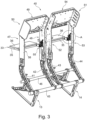
- Figure 1 shows a seat row 1 with a seat direction 2 with two passenger seats 3 and 4.
- position and direction information such as front, back, top and bottom refer to the seat direction 2 and the usage state of the seat row 1.
- the passenger seat 3 has a seat base 5, a backrest 6 and a housing 7 at the back of the backrest 6. Adjoining a front end region of the seat base 5 there is a preferably foldable leg rest 8 which can be folded about a horizontal axis.
- the passenger seat 4 comprises a seat base 9, a backrest 10, a housing 11 and a leg rest 12.
- the seat base 5, 9, the backrests 6, 10 and the leg rests 8, 12 preferably comprise ergonomically shaped upholstery.
- the passenger seats 3 and 4 can be mounted on a cabin floor of a flight cabin of an associated aircraft via two support legs 13 and 14.
- the support leg 13 has a mounting point 17 at a lower end region 16 of a front strut 15 and a further mounting point 20 at a lower end region 19 of a rear strut 18.
- a bracing element 21 is provided between the end regions 16 and 19.
- the support leg 14 has a mounting point 24 and a further Mounting point 27 at a lower end region 26 of a rear strut 25.
- a bracing element 28 is provided between the end regions 23 and 26.
- Seat row 1 also has an outer armrest 29 on the side of passenger seat 3 and an outer armrest 30 on the side of passenger seat 4. Between the two passenger seats 3 and 4, preferably at the height of the two outer armrests 29 and 30, there is a console 31 which can also be used by a passenger as an armrest.
- the respective backrest 6 or 10 is arranged in a shell shape of the respective housing 7 or 11.
- the backrest 6 or 10 is preferably guided movably in the housing 7 or 11 for setting different tilt positions, for example together with the associated slidably mounted seat base 5 or 9.
- the housings 7 and 11 are provided with further elements, e.g. each has additional functions on the back.
- a multimedia unit 32 for digital media is provided, for example with an electronic input and output device or with a touchscreen.
- a folding table top 33 for the respective passenger seats 3 and 4 is designed like a tray table.
- the table tops 33 are shown in an upwardly folded, vertically standing and secured storage or non-use position.
- a storage compartment open at the top with a flexible mesh cover 34 for example for storing magazines or brochures or other objects.
- the table top 33 is explained in more detail below with reference to the passenger seat 3, whereby the table top 33 on the passenger seat 4 is constructed identically.
- the table top 33 which is one in Fig. 2 visible, externally present flat covering 33a, such as a thin cover element, comprises two hingedly connected plate components with a first plate component 35 and a second plate component 36 (see Fig. 3 ), which serves as an additional table top for optionally enlarging a usable table surface of the table top 33.
- a joint arrangement with a fitting 37 is present, comprising a fitting part 38 and a further fitting part 39.
- Fig. 3 shows a basic structure 40 or here an example of a seat frame of the passenger seats 3, 4 according to Fig. 1 and 2 .
- the two table tops 33 are attached to the back of the base structure 40 in a horizontal position, which can be adjusted from the upright position according to Fig. 2 folded down use position, which corresponds to each of the two passenger seats 3, 4 according to the Fig. 1 and 2 belong to.
- the basic structure 40 is preferably designed as a supporting structure for the two passenger seats 3, 4.
- the basic structure 40 is in particular mechanically stable or designed as a load-bearing basic structure 40 with a substantially rigid construction.
- the elements of the basic structure 40 are formed, for example, from a metallic material such as a light metal, for example based on an aluminum material.
- the passenger seats 3, 4 formed with the basic structure 40 can be firmly arranged, for example screwed, on a cabin floor of a passenger cabin via the basic structure 40.
- the basic structure 40 comprises in particular several, here for example four seat dividers 41 to 44, and spars 45, 46 running transversely to the seat direction with the front spar 45 and the rear spar 46 arranged behind it as seen in the seat direction 2.
- the spars 45, 46 are cylindrical profiles with different diameters.
- both bars 45, 46 are arranged on the seat dividers 41-44 or both bars 45, 46 protrude in their longitudinal direction or with their longitudinal axis through respective vertically flat surface sides of the seat dividers 41-44.
- the two beams 45, 46 are spaced apart, in particular mostly aligned parallel to each other.
- the beams 45, 46 are aligned horizontally.
- the basic structure 40 comprises a structural assembly 50 belonging to the passenger seat 3 and a further structural assembly 51 belonging to the passenger seat 4.
- the structural assembly 50 comprises a connecting structural component 49 and two structural components 47 and 48, the respective upper end sections of which are connected via the connecting structural component 49, wherein the connecting structural component 49 bridges a horizontal distance between the two structural components 47 and 48.
- the two structural components 47 and 48 are detachably but firmly connected to the seat dividers 41 and 42 at their respective upper ends.
- the two structural components 47 and 48 are designed to be slightly angled forwards in their upper end section, which is slightly wider than the lower section.
- the structural assembly 50 encompasses the area in which the backrest 6 is present on the finished passenger seat 3.
- the structural components 47, 48 are preferably flat, plate-like, narrow components made of, for example, a honeycomb-like or sandwich structure provided with internal cavities, preferably with an internal wave-valley structure and Covered on both sides by a thin, flat covering element, such as a light metal sheet.
- structural assembly 50 applies accordingly to structural assembly 51, which is constructed in a similar way to structural assembly 50.
- the structural assembly 51 comprises a connecting structural component 54 and two structural components 52 and 53, the respective upper end sections of which are connected via the connecting structural component 54, wherein the connecting structural component 54 bridges a horizontal distance between the two structural components 52 and 53.
- the two structural components 52 and 53 are detachably but firmly connected to the seat dividers 43 and 44 at their respective upper ends.
- a connecting arrangement is provided for the detachable attachment of the respective table top 33 to at least one of the structural components 47, 48 or 52, 53, preferably to both structural components 47, 48 or 52, 53.
- each connecting arrangement 55 and 56 is provided for each of the two table tops 33.
- Each connecting arrangement 55 and 56 has adjustment means 57 for adjusting a mounting position of the table top 33 relative to the associated structural component 47, 48 or 52, 53.
- the adjustment means 57 are designed to set the mounting position of the table top 33 along a first adjustment direction 58 and additionally along a second adjustment direction 59, wherein the first adjustment direction 58 and the second adjustment direction 59 are at an angle to one another, here perpendicular to one another.
- the adjustment means 57 comprise height adjustment means 60, side adjustment means 61 and inclination adjustment means 62.
- the height adjustment means 60 are used to adjust the mounting position of the table top 33 in the first adjustment direction 58 or in the vertical adjustment direction 58, which is accordingly a height adjustment direction.
- the side adjustment means 61 are used to adjust the mounting position of the table top 33 in the second adjustment direction 59 or in the horizontal adjustment direction 59, which is accordingly a side adjustment direction.
- the inclination adjustment means 62 are used to adjust the inclination of the table top 33 in an inclination direction 63 about a joint axis of the respective fitting part 38, 39, i.e. about the pivot axis S of the table top 33 provided by the joint arrangement with the fitting 37 (see Fig. 4 ).
- connection arrangement 55 comprises a plurality of connection components, wherein a first connection component 64 is fastened to the structural component 53 and the first connection component 64 is connected to a second connection component 65 of the connection arrangement 55.
- the second connecting component 65 is connected to the fitting part 39 of the joint arrangement.
- the height adjustment means 60 comprise a screw connection 66 with a first screw element 67 that extends through a first elongated hole 68 in the connecting component 64 and a second screw element 69 that extends through a second elongated hole 70 in the connecting component 64.
- the height position of the table top 33 can be adjusted using the adjustment range that depends on the elongated hole length of the elongated holes 68, 70 and the variably selectable penetration position of the screw elements 67, 69.
- the side adjustment means 61 comprise a screw connection 71 with a first screw element 72 which extends through a first elongated hole 73 in the connecting component 65 and a second screw element 74 which extends through a second elongated hole 75 in the connecting component 65.
- the inclination adjustment means 62 comprise a screw arrangement with a screw element 76 which, when rotated, causes an adjustment according to the adjustment or inclination direction 63 of a part of the joint arrangement about the pivot axis S provided by the joint arrangement in the use position of the table top 33.
Landscapes
- Engineering & Computer Science (AREA)
- Aviation & Aerospace Engineering (AREA)
- Transportation (AREA)
- Mechanical Engineering (AREA)
- Passenger Equipment (AREA)
Description
- Zur Ausstattung von Luftfahrzeugen zum Personentransport wie Passagierflugzeugen sind Fluggastsitze bzw. Sitzreihen mit üblicherweise mehreren Fluggastsitzen nebeneinander in einer Vielzahl von Ausführungsformen bekannt.
- Bei der Konzeption der Fluggastsitze ist es erforderlich, dass eine hoher Nutz- und Bedienkomfort bereitgestellt wird, zum Beispiel mit verschiedenen Funktionen auf engstem Raum und unter Einhaltung von Sicherheitsstandards. Insbesondere ist eine flexible Anpassung der Funktionen bzw. deren Funktionselemente erwünscht.
- Aus der
EP 3 081 492 A1 ist beispielsweise ein Klapptisch zur Anbringung an einer Rückseite einer Rückenlehne eine Fluggastsitzes bekannt. Aus derUS 2019/0283881 A1 ist ein Fluggastsitz mit einem in vertikaler Richtung verstellbarer Geräteträger bekannt. Der Träger für persönliche Geräte umfasst eine Trägerplatte, die in eine Rückseite des Passagiersitzes integriert ist, und eine Klappablageanordnung mit einer Basis, die einstellbar mit der Trägerplatte verbunden ist, um eine vertikale Bewegung der Klappablageanordnung relativ zur Trägerplatte zu ermöglichen. - Aufgabe der vorliegenden Erfindung ist es, einen verbesserten Fluggastsitz bereitzustellen, mit dem ein hoher Nutz- und Bedienkomfort flexibel erfüllbar ist.
- Diese Aufgabe wird durch den unabhängigen Anspruch 1 gelöst.
- Die Erfindung geht aus von einem Fluggastsitz umfassend ein Strukturbauteil, an welchem eine Tischplatte des Fluggastsitzes über eine Gelenkanordnung aufgenommen ist, wobei die Tischplatte um eine Schwenkachse der Gelenkanordnung schwenkbar ist.
- Das Strukturbauteil gehört zu einer mechanisch tragenden Struktur des Fluggastsitzes, wie einer Grundstruktur des Fluggastsitzes. Beispielsweise ist die Grundstruktur als ein Sitz-Gestell vorhanden. Die tragende Struktur des Fluggastsitzes ist eine mechanisch tragende Grundstruktur. Die tragende Struktur des Fluggastsitzes ist z.B. ein starres Gestell des Fluggastsitzes z. B. bestehend aus mehreren mechanisch stabilen Gestell-Abschnitten bzw. Gestell-Elementen wie starren länglichen und/oder flächigen Bauteilen aus zum Beispiel einem Metallwerkstoff. Das Strukturbauteil ist vorzugsweise ein Teil des Gestells bzw. ist ein solches Gestell-Element. Die Gestell-Elemente sind in der Regel miteinander fest verbunden zu der Grundstruktur. Das Gestell bildet beispielsweise die mechanisch stabile räumliche bzw. am fertigen Fluggastsitz innenliegende Grundstruktur des Fluggastsitzes. Das Gestell mit dem Strukturbauteil ist in der Regel von außen am fertigen Fluggastsitz nicht sichtbar, beispielsweise durch eine Umhausung und/oder Polsterungen verdeckt. Das Gestell nimmt auf den Fluggastsitz mit der darin sitzenden Person wirkende Kräfte und/oder Momente auf und leitet diese in benachbarte Abschnitte wie z. B. einen Kabinenboden einer Flugkabine ein, in welcher der Fluggastsitz montiert ist, zum Beispiel angeschraubt an einem Boden der Flugkabine. An dem Gestell sind weitere Elemente des Fluggastsitzes montierbar wie Sitzboden-Polsterungen, Rückenlehnen-Polsterungen, Beinauflagen oder Anbauelemente wie die z. B. klappbare Tischplatte, Armlehnen oder Staufächer des Fluggastsitzes.
- Der Kern der Erfindung liegt darin, dass eine Verbindungsanordnung zur lösbaren Anbringung der Tischplatte an dem Strukturbauteil vorgesehen ist, wobei die Verbindungsanordnung Einstellmittel umfasst zur Einstellung einer Montageposition der Tischplatte relativ zum Strukturbauteil, wobei die Einstellmittel derart ausgebildet sind, dass die Montageposition aus einer Mehrzahl unterschiedlicher Montagepositionen der Tischplatte relativ zum Strukturbauteil auswählbar ist. Damit ist eine Justierung der Tischplatte am Fluggastsitz möglich, insbesondere um die Tischplatte in eine exakte vorgegebene bzw. gewünschte Anbringposition und damit Nutzstellung zu bringen. Mit der Verbindungsanordnung und den Einstellmitteln ist die Tischplatte am Fluggastsitz, insbesondere rückseitig an dem Fluggastsitz, in die gewünschte Anbringposition am Fluggastsitz bringbar, vorzugsweise stufenlos oder in feinstufig sich unterscheidenden Verstellschritten. Die Einstellung der Anbringposition ist insbesondere in Millimeterschritten in der Position veränderbar bzw. einstell- bzw. verstellbar. Demgemäß unterscheiden sich benachbart mögliche Montage- bzw. Anbringpositionen um zum Beispiel circa einen oder mehrere Millimeter bzw. um wenige Winkelgrade, wenn es um eine Neigungseinstellung der Tischplatte im Nutzzustand geht.
- Das Strukturbauteil ist insbesondere ein Bauteil, das sich im Bereich einer Rückenlehne des Fluggastsitzes erstreckt. An einer Grundstruktur sind zwei jeweils längliche plattenartige aufrecht stehende Strukturbauteile vorgesehen, die beidseitig im Bereich der Erstreckung der Rückenlehne des Fluggastsitzes vorhanden sind. Das Strukturbauteil weist eine Sandwich-Struktur auf, um bei geringem Gewicht eine hohe mechanische Stabilität zu erlangen. Die Grundstruktur des Fluggastsitzes umfasst zum Beispiel vorzugsweise zwei in einer Breitenrichtung des Fluggastsitzes horizontal beabstandete und vertikal sich in der Höhe des Fluggastsitzes erstreckende streifenförmige Strukturbauteile. An jedem der beiden, jeweils in einem seitlichen Bereich des Fluggastsitzes über die Höhe der Rückenlehne vorhandenen Strukturbauteile ist vorzugsweise eine Verbindungsanordnung zur lösbaren Anbringung der Tischplatte an den Strukturbauteilen vorgesehen. Denn die Tischplatte ist vorzugsweise an zwei Stellen gelenkig angebracht bzw. aufgehängt an dem Fluggastsitz. Die beiden Stellen betreffen zum Beispiel zwei Stellen an einer hinteren Längskante der Tischplatte. An einem ersten Plattenbauteil der Tischplatte ist in der Regel außerdem ein weiteres Plattenbauteil der Tischplatte bzw. eine Zusatz-Tischplatte gelenkig vorhanden, die heranklappbar und weg- bzw. aufklappbar ist relativ zum ersten Plattenbauteil, das am Strukturbauteil gelenkig angebracht ist.
- Grundsätzlich ist eine gelenkige Anbringung der Tischplatte alternativ an genau einer Stelle bzw. mit genau einem Gelenk an genau einem Strukturbauteil denkbar.
- Vorzugsweise ist die Tischplatte über zwei Anbring- bzw. Montagestellen, die an der Tischplatte zum Beispiel an einer rückwärtigen Stirnseite der Tischplatte vorhanden sind, mit dem Strukturbauteil verbunden. Bevorzugt an beiden Stellen ist die Einstellung der Montageposition vorzugsweise separat bzw. unabhängig von der Einstellung an der anderen Stelle möglich. Mit der Einstellung ist nicht nur die Montageposition fein justierbar bzw. genau einstellbar, sondern auch die räumliche Ausrichtung der Tischplatte. So kann die Tischplatte exakt am Fluggastsitz positioniert werden, so dass die Tischplatte in der Nutzstellung zum Beispiel in eine exakte Seiten-, Höhen und Horizontal-Ausrichtung der Tischplatte bringbar ist, z. B. mit der Flächenseite bzw. der mit der Tischplatte bereitstellbaren Abstellfläche gemäß einer Oberseite der Tischplatte in eine gewünschte Horizontal-Stellung. Dabei kann auch eine im Flugbetrieb herrschende, von der Horizontalen abweichende Neigung der Längsachse des Flugzeuges berücksichtigt werden, so dass über die überwiegende Flugdauer die Tischplatte mit ihrer Tischplatten-Fläche horizontal ausgerichtet ist. Damit ist sichergestellt, dass im Flugbetrieb auf der Tischplatte abgestellte Gegenstände nicht wegrutschen bzw. nicht herunterfallen.
- Vorzugsweise ist die Tischplatte über zwei Anbringstellen, zum Beispiel im Bereich jeweils einer Gelenkanordnung zum Hoch- und Herunterklappen der Tischplatte an dem Fluggastsitz, mit je einer dazugehörigen Seite bzw. einem Strukturbauteil zum Beispiel innenseitig verbunden. Die gegenüberliegenden und horizontal beabstandeten Strukturbauteile bilden zum Beispiel zwei bodenabgestützte Vertikalstützen der Grundstruktur, die regelmäßig im oberen Endbereich der Strukturbauteile ein Querelement umfasst, das die beiden Strukturbauteile miteinander starr verbindet.
- Vorteilhafterweise sind die Einstellmittel ausgebildet, die Montageposition der Tischplatte entlang einer ersten Verstellrichtung einzurichten und zusätzlich die Montageposition der Tischplatte entlang einer zweiten Verstellrichtung einzurichten, wobei die erste Verstellrichtung und die zweite Verstellrichtung zueinander winklig stehen. Vorzugsweise definieren die beiden Verstellrichtungen zwei Raumachsen, die rechtwinklig bzw. senkrecht zueinander stehen bzw. ausgerichtet sind. Die Verstellrichtungen umfassen vorzugsweise genau zwei Raumachsen bzw. Raumrichtungen oder drei Raumachsen, die zueinander senkrecht stehen. Zum Beispiel ist die erste Verstellrichtung eine senkrechte bzw. lotrechte Richtung und eine zweite Verstellrichtung ist eine horizontale Richtung. Eine dritte Verstellrichtung kann eine zur ersten horizontalen Richtung senkrecht stehende weitere horizontale Richtung sein.
- Die Einstellung entlang der ersten Verstellrichtung betrifft zum Beispiel eine Höheneinstellung der Tischplatte, die Einstellung entlang der zweiten Verstellrichtung betrifft zum Beispiel eine Seiteneinstellung der Tischplatte und die Einstellung entlang der dritten Verstellrichtung betrifft zum Beispiel eine Tiefeneinstellung der Tischplatte.
- Eine weitere Verstellrichtung betrifft eine Einstellung der Tischplatte um eine Achse, zum Beispiel für eine Neigungseinstellung der Tischplatte. Dabei wird ein gewünschter Nutzzustand der Tischplatte zugrundegelegt, vorzugsweise bezogen auf eine Neigung der Flugzeuglängsachse im Dauerflugbetrieb bei schräger Ausrichtung der Flugzeuglängsachse, die sich von der Ausrichtung der Längsachse am Boden oder im Sinkflug unterscheidet, da dann die Tischplatte in der Regel nicht genutzt wird.
- Bei einer vorteilhaften Ausbildung der Einstellmittel, wonach die Tischplatte in drei Verstellrichtungen vorzugsweise jeweils unabhängig einstellbar ist, kann die Tischplatte optimal räumlich ausgerichtet werden, z. B. in einer Höhen-, in einer Seiten- und in einer Tiefenposition der Tischplatte relativ zum Strukturbauteil.
- Vorzugsweise sind die Einstellmittel derart gestaltet, dass eine Einstellung der Neigung der Tischplatte in ihrer ausgeklappten Stellung möglich ist. Damit kann die Tischplatte mit ihrer Oberseite in eine horizontale Flächenausrichtung gebracht werden Damit wird im Flugbetrieb erreicht, dass auf der Tischplatte abgestellte Gegenstände wie Trinkgefäße und Geschirr nicht herunterrutschen können, da die Tischplatte horizontal steht.
- Auch ist es von Vorteil, wenn die Tischplatte mit der Gelenkanordnung aus einer an dem Strukturbauteil herangeklappten Aufrecht-Stellung der Tischplatte in eine an dem Strukturbauteil vorstehende Nutzstellung der Tischplatte und zurück aus der Nutzstellung in die Aufrecht-Stellung schwenkbar ist, wobei die Einstellmittel Neigungseinstellmittel umfassen, welche für eine Einstellung der Neigung der Tischplatte in der Nutzstellung der Tischplatte ausgebildet sind.
- Mit der Gelenkanordnung kann die Tischplatte bei Nichtnutzung an zum Beispiel die Rückseite des Fluggastsitzes bzw. an eine Rückseite einer Umhausung des Fluggastsitzes herangeklappt werden. Dann ist die Tischplatte platzsparend untergebracht bzw. mit ihren Flächenseiten vertikal ausgerichtet und ragt nicht z. B. störend hinein in einen Bewegungsraum einer hinter dem Fluggastsitz sitzenden Person, welche die Tischplatte in der Nutzstellung nutzt. Hierfür wird die Tischplatte aus der zum Beispiel nach oben geklappten Aufrecht-Stellung in die Nutzstellung herabgeklappt.
- Mit den Neigungseinstellmitteln ist bei am Fluggastsitz rückseitig abstehender Tischplatte in der Nutzstellung eine flächige Nutzseite der Tischplatte bzw. eine Oberseite der Tischplatte in der Neigung vorzugsweise in eine gewünschte angenähert oder exakt horizontale Ausrichtung bringbar, bezogen auf eine ausgewählte Ausrichtung bzw. Neigung des Fluggastsitzes bzw. dessen Höhenachse. Die Ausrichtung der Höhenachse des Fluggastsitzes eines sich am Boden befindlichen Passagierflugzeuges weicht von der Ausrichtung der Höhenachse des Fluggastsitzes im Flugbetrieb des Passagierflugzeuges ab. Davon abhängig ist auch die Ausrichtung der abgeklappten Tischplatte in der Nutzstellung. Dabei ist es gewünscht, dass in der Nutzstellung die Oberseite der Tischplatte parallel zur Horizontalen ausgerichtet ist. Diese Ausrichtung im Nutzzustand ist vorteilhaft bezogen auf den Flugbetrieb des dazugehörigen Passagierflugzeugs. Dabei ist ein Flugkabinenboden, auf dem der Fluggastsitz montiert ist, in der Regel winklig zur Horizontalen ausgerichtet in Sitzrichtung bzw. nach vorne ansteigend. Vorteilhafterweise ist es mit den Neigungseinstellmittel möglich dass auf der Tischplatte abgestellte Gegenstände wie Trinkgefäße oder Geschirr wie ein Teller stabil auf der Oberseite der Tischplatte abstellbar sind.
- Eine vorteilhafte Abwandlung der Erfindung zeigt sich darin, dass die Einstellmittel Höheneinstellmittel umfassen, welche für eine Einstellung einer Höhen-Montageposition der Tischplatte entlang einer vertikalen Verstellrichtung ausgestaltet sind.
- Die vertikale Verstellrichtung ist bezogen auf einen Einbauzustand der Tischplatte am Fluggastsitz. Mit der vertikalen Verstellrichtung lässt sich eine gewünschte Höhenposition anpassen z. B. an eine jeweils gewünschte Position entlang der Senkrechten bzw. bezogen auf zum Beispiel einen Abstand vom Flugkabinenboden zur Tischplatte.
- Weiter ist es von Vorteil, dass die Einstellmittel Seiteneinstellmittel umfassen, welche für eine Einstellung einer Seiten-Montageposition der Tischplatte entlang einer horizontalen Verstellrichtung ausgestaltet sind.
- Mit den Seiteneinstellmittel ist eine exakte laterale Ausrichtung zum Beispiel in Breitenrichtung bzw. quer zur Sitzrichtung bzw. mittig am Fluggastsitz bzw. beispielsweise zwischen zwei Strukturbauteilen des Fluggastsitzes möglich.
- Es ist überdies vorteilhaft, dass die Einstellmittel eine Schraubverbindung umfassen mit einem durch ein Langloch greifenden Schraubelement, das in einen Gewindeabschnitt einschraubbar ist.
- Die Schraubverbindung stellt eine stabile und platzsparende Möglichkeit zur Einstellung der Montageposition dar. Außerdem ist mit der Schraubverbindung vorteilhaft neben der Einstellung der Montageposition gleichzeitig die Anbringung der Verbindungsanordnung am Strukturbauteil und/oder der Tischplatte und/oder von Elementen der Verbindungsanordnung miteinander einrichtbar.
- Die jeweilige Schraubverbindung umfasst vorteilhaft genau zwei Schraubelemente mit jeweiligem Schraubloch.
- Gemäß einer vorteilhaften Modifikation umfasst die Verbindungsanordnung mehrere Verbindungsbauteile, wobei ein erstes Verbindungsbauteil an dem Strukturbauteil befestigt ist und das erste Verbindungsbauteil mit einem zweiten Verbindungsbauteil der Verbindungsanordnung verbunden ist.
- Damit ist die Anbringung der Verbindungsanordnung am Strukturbauteil einfach bzw. in wenigen Schritten möglich.
- Für die Befestigung des ersten Verbindungsbauteils sind zum Beispiel geeignete Abschnitte an dem ersten Verbindungsbauteil selbst und am Strukturbauteil entsprechend vorbereitet vorhanden zum Beispiel mit Öffnungen für z.B. Nietelemente oder mit Anschrauböffnungen mit einem Innengewinde für dazu passende Schraubmittel mit Außengewinde.
- Die mehreren Verbindungsbauteile der Baueinheit sind bevorzugt mit Schraubmitteln miteinander verbunden. Vorzugsweise greift jedes Schraubelement durch ein zugehöriges Langloch im ersten Verbindungsbauteil.
- Demgemäß ist es vorteilhaft, wenn am ersten Verbindungsbauteil und/oder am zweiten Verbindungsbauteil Verbindungsmittel realisiert sind zur Verbindung des zweiten Verbindungsbauteils mit dem ersten Verbindungsbauteil. Diese Verbindungsmittel sind vorzugsweise Schraubmittel.
- Vorzugsweise sind die Verbindungsbauteile den Einstellmitteln zugehörig bzw. bilden die Verbindungsbauteile die Verbindungsanordnung und gleichzeitig die Einstellmittel.
- Ein anderer Vorteil ergibt sich, wenn das zweite Verbindungsbauteil mit der Gelenkanordnung verbunden ist.
- Vorzugsweise greift das zweite Verbindungsbauteil an der Gelenkanordnung an.
- Vorzugsweise sind das zweite Verbindungsbauteil und die Gelenkanordnung miteinander mit einer Schraubverbindung verbunden. Vorzugsweise mit genau zwei Schraubelementen wie Schrauben mit einem Fein-Außengewinde, die in zwei dazugehörige Schraubbohrungen mit Fein-Innengewinde greifen.
- Die Schraubmittel greifen durch jeweils ein Langloch am zweiten Verbindungsbauteil.
- Die Längserstreckung der z. B. zwei Langlöcher im ersten Verbindungsbauteil sind vorzugsweise parallel untereinander.
- Die Längserstreckung der z. B. zwei Langlöcher im zweiten Verbindungsbauteil sind vorzugsweise parallel untereinander.
- Die Längserstreckung der Langlöcher im ersten Verbindungsbauteil ist vorzugsweise senkrecht zur Längserstreckung der Langlöcher im zweiten Verbindungsbauteil.
- Weiter besteht eine vorteilhafte Ausgestaltung darin, dass die Höheneinstellmittel eine Schraubverbindung umfassen mit einem ersten Schraubelement, das durch ein erstes Langloch greift und einem zweiten Schraubelement, das durch ein zweites Langloch greift. Dies stellt eine stabile Höheneinstellung dar.
- Nachfolgend sind vorteilhafte bzw. vorzugsweise gestaltete Ausbildungen diskutiert, die nicht einschränkend sind bzw. die neben anderen möglichen Varianten stehen.
- Ein jeweiliges Langloch bzw. die paarweise zusammengehörigen beiden Langlöcher der Höheneinstellmittel weisen vorzugsweise keine Innengewinde auf, da die Langlöcher zum Durchgreifen des jeweiligen Schraubelements dienen, jedoch nicht zum Zusammenwirken mit dem Außengewinde des Schraubelements. In Durchgreifrichtung hinter dem Abschnitt mit dem Langloch bzw. dem dahinter anschließenden Bauteilabschnitt ist jedoch vorzugsweise ein Innengewinde vorhanden, in welches das Außengewinde des Schraubelements passend einschraubbar ist.
- Die zur Höheneinstellung, wie auch die zur Seiteneinstellung gehörigen beiden Langlöcher, vorgesehenen paarweisen Langlöcher sind auf ein Langloch-Paar bezogen separat bzw. getrennt voneinander. Das jeweilige Schraubelement ist jeweils in einen passenden Gewindeabschnitt, der im Bauteil hinter dem Langloch in Durchgreifrichtung vorhanden ist, einschraubbar. Das Einschrauben des Schraubelements erfolgt so weit, bis der Abschnitt bzw. das Bauteil mit Langloch geklemmt wird und in seiner Position fixiert ist durch das Schraubelement und das Bauteil mit dem Innengewinde. Die zwei Schraubelemente, die zu einem Langloch-Paar gehören, sind wie die Langlöcher nebeneinander versetzt zueinander, vorzugsweise vertikal versetzt, bei der Seiteneinstellung horizontal bzw. lateral versetzt zueinander.
- Beispielsweise sind am ersten Verbindungsbauteil das erste und das zweite Langloch der Höheneinstellmittel ausgebildet, durch welches das jeweils dazugehörige Schraubelement greift. Ein jeweiliger Gewindeabschnitt für die jeweiligen beiden Schraubelemente ist vorzugsweise im zweiten Verbindungsbauteil vorhanden.
- Nach einem Vorteil der Erfindung umfassen die Seiteneinstellmittel eine Schraubverbindung mit einem ersten Schraubelement, das durch ein erstes Langloch greift und einem zweiten Schraubelement, das durch ein zweites Langloch greift.
- Die Seiteneinstellmittel mit der Schraubverbindung umfasst neben den Schraubelementen und den Langlöchern außerdem jeweils einen ersten Innengewindeabschnitt in einem ersten Loch und einen zweiten Innengewindeabschnitt in einem zweiten Loch, jeweils in einem Bauteil hinter dem zweiten Verbindungsbauteil wie vorzugsweise einem Gelenkteil der Gelenkanordnung.
- Die ohne Innengewinde versehenen Langlöcher sind separat bzw. getrennt voneinander. Am zweiten Einstellbauteil ist ein Langloch der Seiteneinstellmittel ausgebildet, durch welches das dazugehörige Schraubelement greift. Ein jeweiliger Gewindeabschnitt für die beiden Schraubelemente ist vorzugsweise in einem Gelenkbauteil der Gelenkanordnung ausgebildet. Die Innengewindeabschnitte von Höhen- und von Seiteneinstellmittel sind vorzugsweise parallel ausgerichtet bzw. demgemäß die Längsachse der jeweiligen Schraubelemente.
- Das erste Langloch und das zweite Langloch der Höheneinstellmittel und das erstes Langloch der Seiteneinstellmittel sind jeweils separate Langlöcher.
- Entsprechend sind die beiden Langlöchern der Seiteneinstellmittel jeweils separate parallele Langlöcher.
- Weiter ist es von Vorteil, dass die Neigungseinstellmittel ein Schraubelement umfassen, wobei durch Verdrehen des Schraubelements eine Verstellung eines Teils der Gelenkanordnung um die von der Gelenkanordnung bereitgestellte Schwenkachse bedingt. Damit lässt sich einfach und stufenlos beispielsweise mit einem Schraubendreh-Werkzeug die Neigung der Tischplatte in der Nutzstellung einrichten.
- Bevorzugt ist die Tischplatte des Fluggastsitzes mit zwei Verbindungsanordnungen lösbar an zwei voneinander beabstandeten Strukturbauteilen angebracht. Damit wird eine mechanisch stabile Zweipunkt-Anbringung bzw. -Aufhängung der Tischplatte realisiert Vorzugsweise ist an beiden Anbringpunkten eine Gelenkanordnung zum Klappen der Tischplatte realisiert.
- Vorzugsweise findet die Befestigung an einander zugewandten Innen- bzw. Flächenseiten der Strukturbauteile statt. Die Tischplatte umfasst vorzugsweise ein erstes an dem Strukturbauteil angreifendes Plattenbauteil und ein weiteres Plattenbauteil wie z. B. eine Zusatz-Tischplatte, das gelenkig am ersten Plattenbauteil angreift. Das weitere Plattenbauteil kann an das erste Plattenbauteil an dieses parallel herangeklappt oder flächig fluchtend daran verlängernd vorhanden sein. Damit kann die nutzbare Abstell-Fläche eines Tisches umfassend die Tischplatte vergrößert werden. Außerdem kann das weitere Plattenbauteil bei dessen Nichtnutzung, bei Nutzung der Tischplatte kompakt angeklappt werden an z. B. die Oberseite des ersten Plattenbauteils.
- Die Erfindung erstreckt sich zudem auf eine Sitzreihe umfassend mehrere nebeneinander vorhandene Fluggastsitze gemäß einer der oben beschriebenen Ausbildungen. Damit lassen sich die diskutierten Vorteil an einer Sitzreihe mit mehreren Fluggastsitzen in einem Flugzeug erreichen. Die Fluggastsitze sind vorzugsweise lateral fluchtend zueinander vorhanden im Flugzeug.
- Ein Sitzplatz eines Fluggastsitzes weist für ein bequemes Sitzgefühl eines Fluggastes einen vorzugsweise gepolsterten Sitzboden und eine Rückenlehne mit Polsterung auf. In einem Flugzeug sind regelmäßig zwei oder mehr Fluggastsitze fluchtend nebeneinander zu einer Sitzreihe verbunden.
- Nachfolgend sind weitere Merkmale und Vorteile der Erfindung anhand eines schematisch dargestellten Ausführungsbeispiels näher erläutert.
- Im Einzelnen zeigt:
- Fig. 1
- in einer perspektivischen Ansicht schräg von vorne eine Sitzreihe mit zwei Fluggastsitzen jeweils umfassend einen Sitzboden, eine Rückenlehne samt rückseitiger Umhausung und eine Beinauflage,
- Fig. 2
- die Sitzreihe gemäß
Figur 1 in einer perspektivischen Ansicht von schräg hinten, - Fig. 3
- eine Grundstruktur der Fluggastsitze gemäß
Fig. 1 und2 perspektivisch schräg von vorne mit jeweils einer Tischplatte in Nutzstellung, - Fig. 4
- einen vergrößerten Ausschnitt gemäß dem umrandeten Bereich A in
Fig. 3 , - Fig. 5
- einen Ausschnitt der Grundstruktur der Fluggastsitze gemäß
Fig. 3 in einer Frontansicht und - Fig. 6
- einen vergrößerten Ausschnitt gemäß dem umrandeten Bereich B in
Fig. 5 . -
Figur 1 zeigt eine Sitzreihe 1 mit einer Sitzrichtung 2 mit zwei Fluggastsitzen 3 und 4. Nachfolgend beziehen sich Positions- und Richtungsangaben wie vorne, hinten, oben und unten auf die Sitzrichtung 2 und den Nutzzustand der Sitzreihe 1. - Beide Fluggastsitze 3 und 4 sind entsprechend aufgebaut. Der Fluggastsitz 3 weist einen Sitzboden 5, eine Rückenlehne 6 und eine zur Rückenlehne 6 rückseitige Umhausung 7 auf. Im Anschluss an einen vorne liegenden Endbereich des Sitzbodens 5 ist eine vorzugsweise klappbare Beinauflage 8 vorhanden, die um eine horizontale Achse klappbar ist.
- Dementsprechend umfasst der Fluggastsitz 4 einen Sitzboden 9, eine Rückenlehne 10, eine Umhausung 11 und eine Beinauflage 12.
- Die Sitzboden 5, 9, die Rückenlehnen 6, 10 und die Beinauflagen 8, 12 umfassen eine vorzugsweise ergonomisch geformte Polsterung.
- Die Fluggastsitze 3 und 4 sind über zwei Stützbeine 13 und 14 an einem Kabinenboden einer Flugkabine eines dazugehörigen Flugzeuges montierbar.
- Das Stützbein 13 weist hierfür an einem unteren Endbereich 16 einer vorderen Strebe 15 eine Montagestelle 17 und eine weitere Montagestelle 20 an einem unteren Endbereich 19 einer hinteren Strebe 18 auf. Zwischen den Endbereichen 16 und 19 ist ein Verstrebungselement 21 vorgesehen.
- Das Stützbein 14 weist an einem unteren Endbereich 23 einer vorderen Strebe 22 eine Montagestelle 24 und eine weitere Montagestelle 27 an einem unteren Endbereich 26 einer hinteren Strebe 25 auf. Zwischen den Endbereichen 23 und 26 ist ein Verstrebungselement 28 vorgesehen.
- Die Sitzreihe 1 weist zudem eine äußere Armlehne 29 seitlich am Fluggastsitz 3 und eine äußere Armlehne 30 seitlich am Fluggastsitz 4 auf. Zwischen den beiden Fluggastsitzen 3 und 4 ist vorzugsweise auf Höhe der beiden äußeren Armlehnen 29 und 30 eine Konsole 31 vorhanden, welche von einem Fluggast ebenfalls als Armauflage genutzt werden kann.
- In einer Schalenform der jeweiligen Umhausung 7 bzw. 11 ist die jeweils dazugehörige Rückenlehne 6 bzw. 10 angeordnet. Die Rückenlehne 6 bzw. 10 ist vorzugsweise zur Einstellung von unterschiedlichen Kippstellungen beweglich in der Umhausung 7 bzw. 11 geführt, beispielsweise zusammen mit dem dazugehörigen verschiebbar gelagerten Sitzboden 5 bzw. 9.
- Die Umhausungen 7 und 11 sind mit weiteren Elementen versehen, z. B. rückseitig jeweils mit Zusatzfunktionen versehen. In einem oberen rückseitigen Bereich der Umhausungen 7, 11 ist beispielsweise jeweils eine Multimedia-Einheit 32 für digitale Medien vorgesehen, zum Beispiel mit einem elektronischen Ein- und Ausgabegerät bzw. mit einem Touchscreen.
- In einem unterhalb an die Multimedia-Einheit 32 anschließenden bzw. mittleren Bereich ist zum Beispiel jeweils eine klappbare Tischplatte 33 für den jeweiligen Fluggastsitz 3 und 4 wie ein Tablett-Tisch ausgebildet. In
Fig. 2 sind die Tischplatten 33 in einer nach oben herangeklappten, vertikal stehenden und gesicherten Verstau- bzw. Nichtnutzungs-Stellung dargestellt. - Unterhalb der jeweiligen klappbaren Tischplatte 33 ist ein oben offenes Staufach mit einer flexiblen Netzabdeckung 34 beispielswiese zur Unterbringung von Zeitschriften bzw. Prospekten oder anderen Gegenständen vorhanden.
- Nachfolgend wird die Tischplatte 33 mit Bezug auf den Fluggastsitz 3 näher erläutert, wobei die Tischplatte 33 am Fluggastsitz 4 identisch aufgebaut ist.
- Die Tischplatte 33, die eine in
Fig. 2 ersichtliche, außenseitig vorhandene flächige Überdeckung 33a wie zum Beispiel ein dünnes Abdeckelement aufweist, umfasst zwei gelenkig verbundene Plattenbauteile mit einem ersten Plattenbauteil 35 und einem zweiten Plattenbauteil 36 (s.Fig. 3 ), das als Zusatz-Tischplatte dient zur wahlweisen Vergrößerung einer nutzbaren Tischfläche der Tischplatte 33. Zur schwenk- bzw. klappbaren Anordnung der Tischplatte 33 am Fluggastsitz 3 bzw. 4 ist jeweils eine Gelenkanordnung mit einem Beschlag 37 vorhanden, umfassend ein Beschlagteil 38 und ein weiteres Beschlagteil 39. -
Fig. 3 zeigt eine Grundstruktur 40 bzw. hier beispielhaft ein Sitzgestell der Fluggastsitze 3, 4 gemäßFig. 1 und2 . Rückseitig an der Grundstruktur 40 sind die zwei Tischplatten 33 in einer horizontal stehenden, aus der Aufrecht-Stellung gemäßFig. 2 herabgeklappten Nutzstellung dargestellt, die jedem der beiden Fluggastsitze 3, 4 gemäß derFig. 1 und2 zugehörig sind. - Die Grundstruktur 40 ist vorzugsweise als eine tragende Struktur für die beiden Fluggastsitze 3, 4 ausgebildet. Die Grundstruktur 40 ist insbesondere mechanisch stabil bzw. als lastaufnehmende Grundstruktur 40 ausgebildet mit einem im Wesentlichen starren Aufbau. Die Elemente der Grundstruktur 40 sind zum Beispiel aus einem metallischen Material wie einem Leichtmetall zum Beispiel auf Basis eines Aluminium-Werkstoffes gebildet.
- Die mit der Grundstruktur 40 gebildeten Fluggastsitze 3, 4 sind über die Grundstruktur 40 an z. B. einem Kabinenboden einer Fluggastkabine fest anordenbar zum Beispiel anschraubbar. Die Grundstruktur 40 umfasst insbesondere mehrere hier z. B. vier Sitzteiler 41 bis 44, und quer zur Sitzrichtung verlaufende Holme 45, 46 mit dem vorderen Holm 45 und dem in Sitzrichtung 2 gesehen dahinter angeordneten hinteren Holm 46. Die Holme 45, 46 sind zylindrische Profile mit jeweils unterschiedlichem Durchmesser.
- Vorzugsweise sind beide Holme 45, 46 an den Sitzteilern 41-44 angeordnet bzw. es ragen beide Holme 45, 46 in deren Längsrichtung bzw. mit deren Längsachse durch jeweilige vertikal flächig ausgerichtete Flächenseiten der Sitzteiler 41-44 hindurch.
- Vorteilhafterweise verlaufen die zwei Holme 45, 46 beabstandet, insbesondere mehrheitlich parallel zueinander ausgerichtet. Vorteilhafterweise sind die Holme 45, 46 horizontal ausgerichtet.
- Die Grundstruktur 40 umfasst eine zum Fluggastsitz 3 gehörige Strukturbaugruppe 50 und eine zum Fluggastsitz 4 gehörige weitere Strukturbaugruppe 51.
- Die Strukturbaugruppe 50 umfasst ein Verbindungs-Strukturbauteil 49 und zwei Strukturbauteile 47 und 48, deren jeweiliger oberer Endabschnitt über das Verbindungs-Strukturbauteil 49 verbunden sind, wobei das Verbindungs-Strukturbauteil 49 einen horizontalen Abstand zwischen den beiden Strukturbauteile 47 und 48 überbrückt. Die beiden Strukturbauteile 47 und 48 sind mit den Sitzteilern 41 und 42 an deren jeweiligen oberen Ende lösbar aber fest verbunden.
- Die beiden Strukturbauteile 47 und 48 sind in ihrem oberen Endabschnitt, der gegenüber dem unteren Abschnitt etwas breiter ist, räumlich schräg nach vorne leicht abgewinkelt gestaltet.
- Die Strukturbaugruppe 50 umspannt den Bereich, in welchem am fertigen Fluggastsitz 3 die Rückenlehne 6 vorhanden ist.
- Die Strukturbauteile 47, 48 sind vorzugsweise flache plattenartige schmale Bauteile aus zum Beispiel einer wabenartigen bzw. mit inneren Hohlräumen versehenen Sandwich-Struktur, vorzugsweise mit einer inneren Wellen-Tal-Struktur und beidseitiger Abdeckung durch jeweils ein dünnes flächiges Abdeckelement wie z. B. aus einem Leichtmetall-Blech.
- Für die gleichartig zur Strukturbaugruppe 50 aufgebaute Strukturbaugruppe 51 gilt das zur Strukturbaugruppe 50 Gesagte entsprechend.
- Die Strukturbaugruppe 51 umfasst ein Verbindungs-Strukturbauteil 54 und zwei Strukturbauteile 52 und 53, deren jeweiliger oberer Endabschnitt über das Verbindungs-Strukturbauteil 54 verbunden sind, wobei das Verbindungs-Strukturbauteil 54 einen horizontalen Abstand zwischen den beiden Strukturbauteilen 52 und 53 überbrückt. Die beiden Strukturbauteile 52 und 53 sind mit den Sitzteilern 43 und 44 an deren jeweiligen oberen Ende lösbar aber fest verbunden.
- Zur lösbaren Anbringung der jeweiligen Tischplatte 33 an zumindest einem der Strukturbauteile 47, 48 bzw. 52, 53 vorzugsweise an beiden Strukturbauteile 47, 48 bzw. 52, 53 ist eine Verbindungsanordnung vorgesehen.
- Im dargestellten Ausführungsbeispiel sind zwei Verbindungsanordnungen 55 und 56 für jede der beiden Tischplatten 33 vorgesehen. Jede Verbindungsanordnung 55 und 56 weist Einstellmittel 57 zur Einstellung einer Montageposition der Tischplatte 33 relativ zum dazugehörigen Strukturbauteil 47, 48 bzw. 52, 53 auf.
- Die Einstellmittel 57 sind ausgebildet, die Montageposition der Tischplatte 33 entlang einer ersten Verstellrichtung 58 und zusätzlich entlang einer zweiten Verstellrichtung 59 einzurichten, wobei die erste Verstellrichtung 58und die zweite Verstellrichtung 59 zueinander winklig stehen, hier senkrecht aufeinander stehen. Die Einstellmittel 57 umfassen Höheneinstellmittel 60, Seiteneinstellmittel 61 und Neigungseinstellmittel 62.
- Mit den Höheneinstellmitteln 60 erfolgt eine Einstellung der Montageposition der Tischplatte 33 in die erste Verstellrichtung 58 bzw. in die vertikalen Verstellrichtung 58, die demgemäß eine Höhen-Verstellrichtung ist.
- Mit den Seiteneinstellmitteln 61 erfolgt eine Einstellung der Montageposition der Tischplatte 33 in die zweite Verstellrichtung 59 bzw. in die horizontale Verstellrichtung 59, die demgemäß eine Seiten-Verstellrichtung ist.
- Mit den Neigungseinstellmitteln 62 erfolgt in der Tischplatten-Nutzstellung eine Einstellung der Neigung der Tischplatte 33 in einer Neigungsrichtung 63 um eine Gelenkachse des jeweiligen Beschlagteils 38, 39 also um die von der Gelenkanordnung mit dem Beschlag 37 bereitgestellten Schwenkachse S der Tischplatte 33 (s.
Fig. 4 ). - Bezogen auf die Verbindungsanordnung 55, wobei die weitere Verbindungsanordnung 56 entsprechend gestaltet ist, umfasst die Verbindungsanordnung 55 mehrere Verbindungsbauteile, wobei ein erstes Verbindungsbauteil 64 an dem Strukturbauteil 53 befestigt ist und das erste Verbindungsbauteil 64 mit einem zweiten Verbindungsbauteil 65 der Verbindungsanordnung 55 verbunden ist.
- Das zweite Verbindungsbauteil 65 ist mit dem Beschlagteil 39 der Gelenkanordnung verbunden.
- Die Höheneinstellmittel 60 umfassen eine Schraubverbindung 66 mit einem ersten Schraubelement 67, das durch ein erstes Langloch 68 im Verbindungsbauteil 64 greift und einem zweiten Schraubelement 69, das durch ein zweites Langloch 70 im Verbindungsbauteil 64 greift. Mit dem von der Langlochlänge der Langlöcher 68, 70 abhängigen Verstellbereich und der variabel wählbaren Durchgriffposition der Schraubelemente 67, 69 ist die Höhenposition der Tischplatte 33 einstellbar.
- Die Seiteneinstellmittel 61 umfassen eine Schraubverbindung 71 mit einem ersten Schraubelement 72, das durch ein erstes Langloch 73 im Verbindungsbauteil 65 greift und einem zweiten Schraubelement 74, das durch ein zweites Langloch 75 im Verbindungsbauteil 65 greift.
- Die Neigungseinstellmittel 62 umfassen eine Schraubanordnung mit einem Schraubelement 76, das durch Verdrehen eine Verstellung gemäß der Verstell-bzw. Neigungsrichtung 63 eines Teils der Gelenkanordnung um die von der Gelenkanordnung bereitgestellten Schwenkachse S bedingt im Nutzstellung der Tischplatte 33.
-
1 Sitzreihe 35, 36 Plattenbauteil 2 Sitzrichtung 37 Beschlag 3 Fluggastsitz 38, 39 Beschlagteil 4 Fluggastsitz 40 Grundstruktur 5 Sitzboden 41-44 Sitzteiler 6 Rückenlehne 45, 46 Holm 7 Umhausung 47, 48 Strukturbauteil 8 Beinauflage 49 Verbindungs- 9 Sitzboden Strukturbauteil 10 Rückenlehne 50 Strukturbaugruppe 11 Umhausung 51 Strukturbaugruppe 12 Beinauflage 52, 53 Strukturbauteil 13 Stützbein 54 Verbindungs- 14 Stützbein Strukturbauteil 15 Strebe 55, 56 Verbindungsanordnung 16 Endbereich 57 Einstellmittel 17 Montagestelle 58, 59 Verstellrichtung 18 Strebe 60 Höheneinstellmittel 19 Endbereich 61 Seiteneinstellmittel 20 Montagestelle 62 Neigungseinstell- 21 Verstrebungselement mittel 22 Strebe 63 Neigungsrichtung 23 Endbereich 64, 65 Verbindungsbauteil 24 Montagestelle 66 Schraubverbindung 25 Strebe 67 Schraubelement 26 Endbereich 68 Langloch 27 Montagestelle 69 Schraubelement 28 Verstrebungselement 70 Langloch 29 Armlehne 71 Schraubverbindung 30 Armlehne 72 Schraubelement 31 Konsole 73 Langloch 32 Multimedia-Einheit 74 Schraubelement 33 Tischplatte 75 Langloch 33a Überdeckung 76 Schraubelement 34 Staufach
Claims (13)
- Fluggastsitz (3, 4) umfassend ein Strukturbauteil (47, 48, 52, 53), an welchem eine Tischplatte (33) des Fluggastsitzes (3, 4) über eine Gelenkanordnung aufgenommen ist, wobei die Tischplatte (33) um eine Schwenkachse der Gelenkanordnung schwenkbar ist, wobei der Fluggastsitz (3, 4) eine Grundstruktur aufweist, wobei die Grundstruktur eine mechanisch tragende Struktur ist, wobei die Grundstruktur das Strukturbauteil (47, 48, 52, 53) aufweist, wobei die Grundstruktur zwei jeweils längliche plattenartige aufrecht stehende Strukturbauteile aufweist, welche beidseitig im Bereich der Erstreckung einer Rückenlehne des Fluggastsitz vorhanden sind, wobei die Strukturbauteile eine Sandwich-Struktur aufweisen, um bei geringem Gewicht eine hohe mechanische Stabilität zu erlangen, wobei eine Verbindungsanordnung (55, 56) zur lösbaren Anbringung der Tischplatte (33) an dem Strukturbauteil (47, 48, 52, 53) vorgesehen ist, wobei die Verbindungsanordnung (55, 56) Einstellmittel (57) umfasst zur Einstellung einer Montageposition der Tischplatte (33) relativ zum Strukturbauteil (47, 48, 52, 53), wobei die Einstellmittel (57) derart ausgebildet sind, dass die Montageposition aus einer Mehrzahl unterschiedlicher Montagepositionen der Tischplatte (33) relativ zum Strukturbauteil (47, 48, 52, 53) auswählbar ist, wobei die Tischplatte (33) des Fluggastsitzes (3, 4) mit einer Verbindungsanordnung (56) lösbar an einem ersten der zwei Strukturbauteilen (47, 52) und mit einer weiteren Verbindungsanordnung (55) lösbar an einem zweiten der zwei Strukturbauteile (48, 53) angebracht ist.
- Fluggastsitz nach Anspruch 1, dadurch gekennzeichnet, dass die Einstellmittel (57) ausgebildet sind, die Montageposition der Tischplatte (33) entlang einer ersten Verstellrichtung (58) einzurichten und zusätzlich die Montageposition der Tischplatte (33) entlang einer zweiten Verstellrichtung (59) einzurichten, wobei die erste Verstellrichtung (58) und die zweite Verstellrichtung (59) zueinander winklig stehen.
- Fluggastsitz nach Anspruch 1 oder Anspruch 2, dadurch gekennzeichnet, dass die Tischplatte (33) mit der Gelenkanordnung aus einer an dem Strukturbauteil (47, 48, 52, 53) herangeklappten Aufrecht-Stellung der Tischplatte (33) in eine an dem Strukturbauteil (47, 48, 52, 53) vorstehende Nutzstellung der Tischplatte (33) und zurück aus der Nutzstellung in die Aufrecht-Stellung schwenkbar ist, wobei die Einstellmittel (57) Neigungseinstellmittel (62) umfassen, welche für eine Einstellung der Neigung der Tischplatte (33) in der Nutzstellung der Tischplatte (33) ausgebildet sind.
- Fluggastsitz nach einem der vorhergehenden Ansprüche, dadurch gekennzeichnet, dass die Einstellmittel (57) Höheneinstellmittel (60) umfassen, welche für eine Einstellung einer Höhen-Montageposition der Tischplatte (33) entlang einer vertikalen Verstellrichtung ausgestaltet sind.
- Fluggastsitz nach einem der vorhergehenden Ansprüche, dadurch gekennzeichnet, dass die Einstellmittel (57) Seiteneinstellmittel (61) umfassen, welche für eine Einstellung einer Seiten-Montageposition der Tischplatte (33) entlang einer horizontalen Verstellrichtung ausgestaltet sind.
- Fluggastsitz nach einem der vorhergehenden Ansprüche, dadurch gekennzeichnet, dass die Einstellmittel (57) eine Schraubverbindung umfassen mit einem durch ein Langloch (68,70, 73, 75) greifenden Schraubelement (67, 69, 72, 74), das in einen Gewindeabschnitt einschraubbar ist.
- Fluggastsitz nach einem der vorhergehenden Ansprüche, dadurch gekennzeichnet, dass die Verbindungsanordnung (55, 56) mehrere Verbindungsbauteile umfasst, wobei ein erstes Verbindungsbauteil (64) an dem Strukturbauteil (47, 48, 52, 53) befestigt ist und das erste Verbindungsbauteil (64) mit einem zweiten Verbindungsbauteil (65) der Verbindungsanordnung (55, 56) verbunden ist.
- Fluggastsitz nach einem der vorhergehenden Ansprüche, dadurch gekennzeichnet, dass das zweite Verbindungsbauteil (65) mit der Gelenkanordnung verbunden ist.
- Fluggastsitz nach einem der vorhergehenden Ansprüche, dadurch gekennzeichnet, dass die Höheneinstellmittel (60) eine Schraubverbindung umfassen mit einem ersten Schraubelement (67), das durch ein erstes Langloch (68) greift und einem zweiten Schraubelement (69), das durch ein zweites Langloch (70) greift.
- Fluggastsitz nach einem der vorhergehenden Ansprüche, dadurch gekennzeichnet, dass die Seiteneinstellmittel (61) eine Schraubverbindung umfassen mit einem ersten Schraubelement (72), das durch ein erstes Langloch (73) greift und einem zweiten Schraubelement (74), das durch ein zweites Langloch (75) greift.
- Fluggastsitz nach einem der vorhergehenden Ansprüche, dadurch gekennzeichnet, dass die Neigungseinstellmittel (62) ein Schraubelement (76) umfassen, wobei durch Verdrehen des Schraubelements (76) eine Verstellung eines Teils der Gelenkanordnung um die von der Gelenkanordnung bereitgestellten Schwenkachse bedingt.
- Fluggastsitz nach einem der vorhergehenden Ansprüche, dadurch gekennzeichnet, dass die gegenüberliegenden und horizontal beabstandeten Strukturbauteile im oberen Endbereich der Strukturbauteile ein Querelement umfassen, welche die beiden Strukturbauteile miteinander starr verbindet.
- Sitzreihe (1) umfassend mehrere nebeneinander vorhandene Fluggastsitze (3, 4) gemäß einem der vorhergehenden Ansprüche.
Applications Claiming Priority (2)
| Application Number | Priority Date | Filing Date | Title |
|---|---|---|---|
| DE102020106031.9A DE102020106031A1 (de) | 2020-03-05 | 2020-03-05 | Fluggastsitz und Sitzreihe |
| PCT/EP2021/055459 WO2021175990A1 (de) | 2020-03-05 | 2021-03-04 | Fluggastsitz und sitzreihe |
Publications (2)
| Publication Number | Publication Date |
|---|---|
| EP4045356A1 EP4045356A1 (de) | 2022-08-24 |
| EP4045356B1 true EP4045356B1 (de) | 2025-01-01 |
Family
ID=75203256
Family Applications (1)
| Application Number | Title | Priority Date | Filing Date |
|---|---|---|---|
| EP21714100.1A Active EP4045356B1 (de) | 2020-03-05 | 2021-03-04 | Fluggastsitz und sitzreihe |
Country Status (5)
| Country | Link |
|---|---|
| US (1) | US11919646B2 (de) |
| EP (1) | EP4045356B1 (de) |
| CN (1) | CN115210109B (de) |
| DE (1) | DE102020106031A1 (de) |
| WO (1) | WO2021175990A1 (de) |
Families Citing this family (2)
| Publication number | Priority date | Publication date | Assignee | Title |
|---|---|---|---|---|
| DE102020106029A1 (de) * | 2020-03-05 | 2021-09-09 | Zim Flugsitz Gmbh | Fluggastsitz und Sitzreihe |
| DE102020106037A1 (de) * | 2020-03-05 | 2021-09-09 | Zim Flugsitz Gmbh | Fluggastsitz und Sitzreihe |
Citations (2)
| Publication number | Priority date | Publication date | Assignee | Title |
|---|---|---|---|---|
| US3968992A (en) * | 1974-12-20 | 1976-07-13 | Universal Oil Products Company | Fold down table for aircraft seat |
| US20080073946A1 (en) * | 2006-09-21 | 2008-03-27 | Kathie Maione | Adjusting mechanism for a chair mounted keyboard and mouse platform |
Family Cites Families (21)
| Publication number | Priority date | Publication date | Assignee | Title |
|---|---|---|---|---|
| US3795422A (en) | 1972-04-04 | 1974-03-05 | Air Specialties Inc | Seat mounted food tray with vanity mirror |
| US4281874A (en) | 1979-05-25 | 1981-08-04 | Koehler-Dayton, Inc. | Aircraft seat with cantilevered tray table |
| DE3811939A1 (de) * | 1988-04-11 | 1989-10-19 | Buderus Sell | Fluggastsitz und verfahren zu seiner herstellung |
| US5046433A (en) * | 1989-05-22 | 1991-09-10 | Randall Kramer | Adjustable folding tray apparatus for attachment to a vehicle seat back |
| GB2239639A (en) * | 1990-01-03 | 1991-07-10 | Lin Chun Nan | Folding tray for a vehicle seat |
| US5221070A (en) * | 1991-04-05 | 1993-06-22 | Heilmer Arthur W | Adjustable book holder |
| US5370060A (en) * | 1993-06-11 | 1994-12-06 | Wang; Liwen Y. | Multipurpose automobile foldaway table |
| DE19516011C1 (de) | 1995-05-02 | 1996-08-08 | Daimler Benz Ag | Klapptisch für Fahrzeuge |
| ES2291108B1 (es) * | 2006-02-03 | 2008-11-16 | Figueras International Seating, S.A. | Mejoras del montaje de palas de atril en butacas. |
| DE202009000895U1 (de) * | 2009-01-23 | 2009-07-02 | Herbert, Karl-Walter | Einstellbare Halteeinrichtung für Bordcomputer in Kraftfahrzeugen |
| US8336957B2 (en) | 2009-09-29 | 2012-12-25 | Zodiac Seats Us Llc | Tray table |
| US9527456B2 (en) * | 2012-11-05 | 2016-12-27 | Kinetix Ag | Device for retaining flat, approximately rectangular appliances such as tablet computers or mobile telephones in the interior of a motor vehicle |
| CN104290664B (zh) | 2013-07-16 | 2016-10-05 | 李宛豫 | 翻转式脚托 |
| CN105691265A (zh) * | 2014-11-24 | 2016-06-22 | 林艺雯 | 一种置于交通座椅靠背的双桌面折叠桌 |
| DE202015101911U1 (de) * | 2015-04-17 | 2015-05-05 | Josef Fellinger | Klapptisch |
| CN104842887B (zh) * | 2015-04-28 | 2017-10-17 | 陕西理工学院 | 一种笔记本电脑架 |
| US10696407B2 (en) | 2015-08-24 | 2020-06-30 | Safran Seats Usa Llc | Tray table arms with rotation stopper override |
| CN107539182A (zh) * | 2016-06-27 | 2018-01-05 | 丽盟有限公司 | 扶手桌 |
| GB2552393A (en) | 2016-06-27 | 2018-01-24 | Liq Meng Corp | Armrest table |
| WO2018187070A1 (en) | 2017-04-04 | 2018-10-11 | Timco Aviation Services, Inc. | Seat system with stowable tray |
| US10562635B2 (en) * | 2018-03-19 | 2020-02-18 | The Boeing Company | Personal device carrier and a passenger seat |
-
2020
- 2020-03-05 DE DE102020106031.9A patent/DE102020106031A1/de active Pending
-
2021
- 2021-03-04 CN CN202180019083.7A patent/CN115210109B/zh active Active
- 2021-03-04 WO PCT/EP2021/055459 patent/WO2021175990A1/de not_active Ceased
- 2021-03-04 EP EP21714100.1A patent/EP4045356B1/de active Active
-
2022
- 2022-08-10 US US17/818,743 patent/US11919646B2/en active Active
Patent Citations (2)
| Publication number | Priority date | Publication date | Assignee | Title |
|---|---|---|---|---|
| US3968992A (en) * | 1974-12-20 | 1976-07-13 | Universal Oil Products Company | Fold down table for aircraft seat |
| US20080073946A1 (en) * | 2006-09-21 | 2008-03-27 | Kathie Maione | Adjusting mechanism for a chair mounted keyboard and mouse platform |
Also Published As
| Publication number | Publication date |
|---|---|
| DE102020106031A1 (de) | 2021-09-09 |
| CN115210109B (zh) | 2023-07-14 |
| EP4045356A1 (de) | 2022-08-24 |
| US20220380055A1 (en) | 2022-12-01 |
| US11919646B2 (en) | 2024-03-05 |
| CN115210109A (zh) | 2022-10-18 |
| WO2021175990A1 (de) | 2021-09-10 |
Similar Documents
| Publication | Publication Date | Title |
|---|---|---|
| EP1252038B1 (de) | Fahrzeugsitz für flug- oder kraftfahrzeuge | |
| EP1152917B1 (de) | Kindersitz, insbesondere zur mobilen verwendung in einem flugzeug | |
| EP0268749A1 (de) | Fahrzeugsitz | |
| EP4045356B1 (de) | Fluggastsitz und sitzreihe | |
| DE3539258C2 (de) | Hintersitzanordnung in einem Kraftfahrzeug mit aus der Rückenlehne herausklappbarer Armlehne | |
| DE69000982T2 (de) | Umruestbarer fluggastsitz mit einer entfernbaren abstellplatte. | |
| EP4045406B1 (de) | Fluggastsitz mit einer steckverbindung | |
| EP1759991A1 (de) | Anordnung zum Sitzen und Liegen | |
| DE10105589C1 (de) | Umklappbare Rückenlehne für einen Fahrzeugsitz | |
| EP0941168A1 (de) | Variabler sitz, insbesondere für verkehrssysteme | |
| EP4114732B1 (de) | Fluggastsitz und sitzreihe | |
| EP4114731A1 (de) | Fluggastsitz mit umhausung | |
| EP3967185B1 (de) | Polstermöbelanordnung und wohnlandschaft mit einer polstermöbelanordnung | |
| EP4114733B1 (de) | Fluggastsitz und sitzreihe | |
| EP3785984B1 (de) | Sitzgestell für eine fahrzeugsitzanordnung | |
| DE3714954A1 (de) | Sitz fuer fahrzeuge, insbesondere personenkraftfahrzeuge | |
| DE202006005981U1 (de) | Beinstütze für einen Fahrzeugsitz | |
| EP4114730B1 (de) | Tischplatte für einen fluggastsitz | |
| DE102004025980B4 (de) | Sitzrückenlehne für ein Besatzungs-Aufenthaltsabteil eines Flugzeugs | |
| DE202016102640U1 (de) | Flugzeugdivan | |
| DE102007023371B4 (de) | Fahrzeugsitz mit verschiebbaren Querstreben und Kraftfahrzeug mit einem solchen Fahrzeugsitz | |
| DE102004018161B3 (de) | Rückenlehne mit Ausstellplatte | |
| DE102006049036B3 (de) | Stuhl | |
| DE202005005799U1 (de) | Trennwandelement und Arbeitsplatzanordnung mit diesem | |
| DE102019117429A1 (de) | Flugzeugkabinenvorrichtung |
Legal Events
| Date | Code | Title | Description |
|---|---|---|---|
| STAA | Information on the status of an ep patent application or granted ep patent |
Free format text: STATUS: UNKNOWN |
|
| STAA | Information on the status of an ep patent application or granted ep patent |
Free format text: STATUS: THE INTERNATIONAL PUBLICATION HAS BEEN MADE |
|
| PUAI | Public reference made under article 153(3) epc to a published international application that has entered the european phase |
Free format text: ORIGINAL CODE: 0009012 |
|
| STAA | Information on the status of an ep patent application or granted ep patent |
Free format text: STATUS: REQUEST FOR EXAMINATION WAS MADE |
|
| 17P | Request for examination filed |
Effective date: 20220517 |
|
| AK | Designated contracting states |
Kind code of ref document: A1 Designated state(s): AL AT BE BG CH CY CZ DE DK EE ES FI FR GB GR HR HU IE IS IT LI LT LU LV MC MK MT NL NO PL PT RO RS SE SI SK SM TR |
|
| STAA | Information on the status of an ep patent application or granted ep patent |
Free format text: STATUS: EXAMINATION IS IN PROGRESS |
|
| DAV | Request for validation of the european patent (deleted) | ||
| DAX | Request for extension of the european patent (deleted) | ||
| 17Q | First examination report despatched |
Effective date: 20230601 |
|
| GRAP | Despatch of communication of intention to grant a patent |
Free format text: ORIGINAL CODE: EPIDOSNIGR1 |
|
| STAA | Information on the status of an ep patent application or granted ep patent |
Free format text: STATUS: GRANT OF PATENT IS INTENDED |
|
| GRAJ | Information related to disapproval of communication of intention to grant by the applicant or resumption of examination proceedings by the epo deleted |
Free format text: ORIGINAL CODE: EPIDOSDIGR1 |
|
| STAA | Information on the status of an ep patent application or granted ep patent |
Free format text: STATUS: EXAMINATION IS IN PROGRESS |
|
| INTG | Intention to grant announced |
Effective date: 20240703 |
|
| INTC | Intention to grant announced (deleted) | ||
| GRAP | Despatch of communication of intention to grant a patent |
Free format text: ORIGINAL CODE: EPIDOSNIGR1 |
|
| STAA | Information on the status of an ep patent application or granted ep patent |
Free format text: STATUS: GRANT OF PATENT IS INTENDED |
|
| INTG | Intention to grant announced |
Effective date: 20240904 |
|
| GRAS | Grant fee paid |
Free format text: ORIGINAL CODE: EPIDOSNIGR3 |
|
| GRAA | (expected) grant |
Free format text: ORIGINAL CODE: 0009210 |
|
| STAA | Information on the status of an ep patent application or granted ep patent |
Free format text: STATUS: THE PATENT HAS BEEN GRANTED |
|
| AK | Designated contracting states |
Kind code of ref document: B1 Designated state(s): AL AT BE BG CH CY CZ DE DK EE ES FI FR GB GR HR HU IE IS IT LI LT LU LV MC MK MT NL NO PL PT RO RS SE SI SK SM TR |
|
| REG | Reference to a national code |
Ref country code: GB Ref legal event code: FG4D Free format text: NOT ENGLISH |
|
| REG | Reference to a national code |
Ref country code: DE Ref legal event code: R096 Ref document number: 502021006273 Country of ref document: DE |
|
| REG | Reference to a national code |
Ref country code: CH Ref legal event code: EP |
|
| REG | Reference to a national code |
Ref country code: IE Ref legal event code: FG4D Free format text: LANGUAGE OF EP DOCUMENT: GERMAN |
|
| REG | Reference to a national code |
Ref country code: DE Ref legal event code: R082 Ref document number: 502021006273 Country of ref document: DE Representative=s name: RAVENSPAT PATENTANWAELTE PARTNERSCHAFT MBB, DE |
|
| PGFP | Annual fee paid to national office [announced via postgrant information from national office to epo] |
Ref country code: DE Payment date: 20250319 Year of fee payment: 5 |
|
| PGFP | Annual fee paid to national office [announced via postgrant information from national office to epo] |
Ref country code: AT Payment date: 20250417 Year of fee payment: 5 |
|
| REG | Reference to a national code |
Ref country code: LT Ref legal event code: MG9D |
|
| PGFP | Annual fee paid to national office [announced via postgrant information from national office to epo] |
Ref country code: GB Payment date: 20250324 Year of fee payment: 5 |
|
| REG | Reference to a national code |
Ref country code: NL Ref legal event code: MP Effective date: 20250101 |
|
| PG25 | Lapsed in a contracting state [announced via postgrant information from national office to epo] |
Ref country code: NL Free format text: LAPSE BECAUSE OF FAILURE TO SUBMIT A TRANSLATION OF THE DESCRIPTION OR TO PAY THE FEE WITHIN THE PRESCRIBED TIME-LIMIT Effective date: 20250101 |
|
| PG25 | Lapsed in a contracting state [announced via postgrant information from national office to epo] |
Ref country code: FI Free format text: LAPSE BECAUSE OF FAILURE TO SUBMIT A TRANSLATION OF THE DESCRIPTION OR TO PAY THE FEE WITHIN THE PRESCRIBED TIME-LIMIT Effective date: 20250101 |
|
| PG25 | Lapsed in a contracting state [announced via postgrant information from national office to epo] |
Ref country code: PL Free format text: LAPSE BECAUSE OF FAILURE TO SUBMIT A TRANSLATION OF THE DESCRIPTION OR TO PAY THE FEE WITHIN THE PRESCRIBED TIME-LIMIT Effective date: 20250101 |
|
| PG25 | Lapsed in a contracting state [announced via postgrant information from national office to epo] |
Ref country code: ES Free format text: LAPSE BECAUSE OF FAILURE TO SUBMIT A TRANSLATION OF THE DESCRIPTION OR TO PAY THE FEE WITHIN THE PRESCRIBED TIME-LIMIT Effective date: 20250101 |
|
| PG25 | Lapsed in a contracting state [announced via postgrant information from national office to epo] |
Ref country code: NO Free format text: LAPSE BECAUSE OF FAILURE TO SUBMIT A TRANSLATION OF THE DESCRIPTION OR TO PAY THE FEE WITHIN THE PRESCRIBED TIME-LIMIT Effective date: 20250401 Ref country code: IS Free format text: LAPSE BECAUSE OF FAILURE TO SUBMIT A TRANSLATION OF THE DESCRIPTION OR TO PAY THE FEE WITHIN THE PRESCRIBED TIME-LIMIT Effective date: 20250501 |
|
| PGFP | Annual fee paid to national office [announced via postgrant information from national office to epo] |
Ref country code: IT Payment date: 20250430 Year of fee payment: 5 |
|
| PG25 | Lapsed in a contracting state [announced via postgrant information from national office to epo] |
Ref country code: HR Free format text: LAPSE BECAUSE OF FAILURE TO SUBMIT A TRANSLATION OF THE DESCRIPTION OR TO PAY THE FEE WITHIN THE PRESCRIBED TIME-LIMIT Effective date: 20250101 |
|
| PG25 | Lapsed in a contracting state [announced via postgrant information from national office to epo] |
Ref country code: PT Free format text: LAPSE BECAUSE OF FAILURE TO SUBMIT A TRANSLATION OF THE DESCRIPTION OR TO PAY THE FEE WITHIN THE PRESCRIBED TIME-LIMIT Effective date: 20250502 Ref country code: LV Free format text: LAPSE BECAUSE OF FAILURE TO SUBMIT A TRANSLATION OF THE DESCRIPTION OR TO PAY THE FEE WITHIN THE PRESCRIBED TIME-LIMIT Effective date: 20250101 |
|
| PG25 | Lapsed in a contracting state [announced via postgrant information from national office to epo] |
Ref country code: GR Free format text: LAPSE BECAUSE OF FAILURE TO SUBMIT A TRANSLATION OF THE DESCRIPTION OR TO PAY THE FEE WITHIN THE PRESCRIBED TIME-LIMIT Effective date: 20250402 Ref country code: BG Free format text: LAPSE BECAUSE OF FAILURE TO SUBMIT A TRANSLATION OF THE DESCRIPTION OR TO PAY THE FEE WITHIN THE PRESCRIBED TIME-LIMIT Effective date: 20250101 |
|
| PG25 | Lapsed in a contracting state [announced via postgrant information from national office to epo] |
Ref country code: CZ Free format text: LAPSE BECAUSE OF FAILURE TO SUBMIT A TRANSLATION OF THE DESCRIPTION OR TO PAY THE FEE WITHIN THE PRESCRIBED TIME-LIMIT Effective date: 20250101 |
|
| PG25 | Lapsed in a contracting state [announced via postgrant information from national office to epo] |
Ref country code: SE Free format text: LAPSE BECAUSE OF FAILURE TO SUBMIT A TRANSLATION OF THE DESCRIPTION OR TO PAY THE FEE WITHIN THE PRESCRIBED TIME-LIMIT Effective date: 20250101 |
|
| REG | Reference to a national code |
Ref country code: DE Ref legal event code: R097 Ref document number: 502021006273 Country of ref document: DE |
|
| PG25 | Lapsed in a contracting state [announced via postgrant information from national office to epo] |
Ref country code: SM Free format text: LAPSE BECAUSE OF FAILURE TO SUBMIT A TRANSLATION OF THE DESCRIPTION OR TO PAY THE FEE WITHIN THE PRESCRIBED TIME-LIMIT Effective date: 20250101 |
|
| PG25 | Lapsed in a contracting state [announced via postgrant information from national office to epo] |
Ref country code: DK Free format text: LAPSE BECAUSE OF FAILURE TO SUBMIT A TRANSLATION OF THE DESCRIPTION OR TO PAY THE FEE WITHIN THE PRESCRIBED TIME-LIMIT Effective date: 20250101 |
|
| PG25 | Lapsed in a contracting state [announced via postgrant information from national office to epo] |
Ref country code: MC Free format text: LAPSE BECAUSE OF FAILURE TO SUBMIT A TRANSLATION OF THE DESCRIPTION OR TO PAY THE FEE WITHIN THE PRESCRIBED TIME-LIMIT Effective date: 20250101 |
|
| PG25 | Lapsed in a contracting state [announced via postgrant information from national office to epo] |
Ref country code: EE Free format text: LAPSE BECAUSE OF FAILURE TO SUBMIT A TRANSLATION OF THE DESCRIPTION OR TO PAY THE FEE WITHIN THE PRESCRIBED TIME-LIMIT Effective date: 20250101 |
|
| REG | Reference to a national code |
Ref country code: CH Ref legal event code: H13 Free format text: ST27 STATUS EVENT CODE: U-0-0-H10-H13 (AS PROVIDED BY THE NATIONAL OFFICE) Effective date: 20251023 |
|
| PG25 | Lapsed in a contracting state [announced via postgrant information from national office to epo] |
Ref country code: RO Free format text: LAPSE BECAUSE OF FAILURE TO SUBMIT A TRANSLATION OF THE DESCRIPTION OR TO PAY THE FEE WITHIN THE PRESCRIBED TIME-LIMIT Effective date: 20250101 |
|
| PG25 | Lapsed in a contracting state [announced via postgrant information from national office to epo] |
Ref country code: SK Free format text: LAPSE BECAUSE OF FAILURE TO SUBMIT A TRANSLATION OF THE DESCRIPTION OR TO PAY THE FEE WITHIN THE PRESCRIBED TIME-LIMIT Effective date: 20250101 |
|
| PLBE | No opposition filed within time limit |
Free format text: ORIGINAL CODE: 0009261 |
|
| STAA | Information on the status of an ep patent application or granted ep patent |
Free format text: STATUS: NO OPPOSITION FILED WITHIN TIME LIMIT |
|
| PG25 | Lapsed in a contracting state [announced via postgrant information from national office to epo] |
Ref country code: LU Free format text: LAPSE BECAUSE OF NON-PAYMENT OF DUE FEES Effective date: 20250304 |
|
| 26N | No opposition filed |
Effective date: 20251002 |
|
| REG | Reference to a national code |
Ref country code: BE Ref legal event code: MM Effective date: 20250331 |
|
| PG25 | Lapsed in a contracting state [announced via postgrant information from national office to epo] |
Ref country code: BE Free format text: LAPSE BECAUSE OF NON-PAYMENT OF DUE FEES Effective date: 20250331 |
|
| PG25 | Lapsed in a contracting state [announced via postgrant information from national office to epo] |
Ref country code: CH Free format text: LAPSE BECAUSE OF NON-PAYMENT OF DUE FEES Effective date: 20250331 |
|
| PG25 | Lapsed in a contracting state [announced via postgrant information from national office to epo] |
Ref country code: IE Free format text: LAPSE BECAUSE OF NON-PAYMENT OF DUE FEES Effective date: 20250304 |
|
| PGFP | Annual fee paid to national office [announced via postgrant information from national office to epo] |
Ref country code: FR Payment date: 20260324 Year of fee payment: 6 |