EP4045203B1 - Schnelle quench-leitung - Google Patents
Schnelle quench-leitung Download PDFInfo
- Publication number
- EP4045203B1 EP4045203B1 EP20801073.6A EP20801073A EP4045203B1 EP 4045203 B1 EP4045203 B1 EP 4045203B1 EP 20801073 A EP20801073 A EP 20801073A EP 4045203 B1 EP4045203 B1 EP 4045203B1
- Authority
- EP
- European Patent Office
- Prior art keywords
- metal strip
- metal
- coil
- temperature
- quenching
- Prior art date
- Legal status (The legal status is an assumption and is not a legal conclusion. Google has not performed a legal analysis and makes no representation as to the accuracy of the status listed.)
- Active
Links
Images


Classifications
-
- C—CHEMISTRY; METALLURGY
- C22—METALLURGY; FERROUS OR NON-FERROUS ALLOYS; TREATMENT OF ALLOYS OR NON-FERROUS METALS
- C22F—CHANGING THE PHYSICAL STRUCTURE OF NON-FERROUS METALS AND NON-FERROUS ALLOYS
- C22F1/00—Changing the physical structure of non-ferrous metals or alloys by heat treatment or by hot or cold working
- C22F1/04—Changing the physical structure of non-ferrous metals or alloys by heat treatment or by hot or cold working of aluminium or alloys based thereon
-
- B—PERFORMING OPERATIONS; TRANSPORTING
- B21—MECHANICAL METAL-WORKING WITHOUT ESSENTIALLY REMOVING MATERIAL; PUNCHING METAL
- B21B—ROLLING OF METAL
- B21B37/00—Control devices or methods specially adapted for metal-rolling mills or the work produced thereby
- B21B37/74—Temperature control, e.g. by cooling or heating the rolls or the product
- B21B37/76—Cooling control on the run-out table
-
- C—CHEMISTRY; METALLURGY
- C21—METALLURGY OF IRON
- C21D—MODIFYING THE PHYSICAL STRUCTURE OF FERROUS METALS; GENERAL DEVICES FOR HEAT TREATMENT OF FERROUS OR NON-FERROUS METALS OR ALLOYS; MAKING METAL MALLEABLE, e.g. BY DECARBURISATION OR TEMPERING
- C21D1/00—General methods or devices for heat treatment, e.g. annealing, hardening, quenching or tempering
- C21D1/18—Hardening; Quenching with or without subsequent tempering
-
- C—CHEMISTRY; METALLURGY
- C21—METALLURGY OF IRON
- C21D—MODIFYING THE PHYSICAL STRUCTURE OF FERROUS METALS; GENERAL DEVICES FOR HEAT TREATMENT OF FERROUS OR NON-FERROUS METALS OR ALLOYS; MAKING METAL MALLEABLE, e.g. BY DECARBURISATION OR TEMPERING
- C21D1/00—General methods or devices for heat treatment, e.g. annealing, hardening, quenching or tempering
- C21D1/62—Quenching devices
-
- B—PERFORMING OPERATIONS; TRANSPORTING
- B21—MECHANICAL METAL-WORKING WITHOUT ESSENTIALLY REMOVING MATERIAL; PUNCHING METAL
- B21B—ROLLING OF METAL
- B21B45/00—Devices for surface or other treatment of work, specially combined with or arranged in, or specially adapted for use in connection with, metal-rolling mills
- B21B45/02—Devices for surface or other treatment of work, specially combined with or arranged in, or specially adapted for use in connection with, metal-rolling mills for lubricating, cooling, or cleaning
- B21B45/0203—Cooling
- B21B45/0206—Coolants
-
- B—PERFORMING OPERATIONS; TRANSPORTING
- B21—MECHANICAL METAL-WORKING WITHOUT ESSENTIALLY REMOVING MATERIAL; PUNCHING METAL
- B21C—MANUFACTURE OF METAL SHEETS, WIRE, RODS, TUBES, PROFILES OR LIKE SEMI-MANUFACTURED PRODUCTS OTHERWISE THAN BY ROLLING; AUXILIARY OPERATIONS USED IN CONNECTION WITH METAL-WORKING WITHOUT ESSENTIALLY REMOVING MATERIAL
- B21C47/00—Winding-up, coiling or winding-off metal wire, metal band or other flexible metal material characterised by features relevant to metal processing only
- B21C47/16—Unwinding or uncoiling
- B21C47/18—Unwinding or uncoiling from reels or drums
-
- B—PERFORMING OPERATIONS; TRANSPORTING
- B21—MECHANICAL METAL-WORKING WITHOUT ESSENTIALLY REMOVING MATERIAL; PUNCHING METAL
- B21C—MANUFACTURE OF METAL SHEETS, WIRE, RODS, TUBES, PROFILES OR LIKE SEMI-MANUFACTURED PRODUCTS OTHERWISE THAN BY ROLLING; AUXILIARY OPERATIONS USED IN CONNECTION WITH METAL-WORKING WITHOUT ESSENTIALLY REMOVING MATERIAL
- B21C47/00—Winding-up, coiling or winding-off metal wire, metal band or other flexible metal material characterised by features relevant to metal processing only
- B21C47/26—Special arrangements with regard to simultaneous or subsequent treatment of the material
-
- B—PERFORMING OPERATIONS; TRANSPORTING
- B21—MECHANICAL METAL-WORKING WITHOUT ESSENTIALLY REMOVING MATERIAL; PUNCHING METAL
- B21C—MANUFACTURE OF METAL SHEETS, WIRE, RODS, TUBES, PROFILES OR LIKE SEMI-MANUFACTURED PRODUCTS OTHERWISE THAN BY ROLLING; AUXILIARY OPERATIONS USED IN CONNECTION WITH METAL-WORKING WITHOUT ESSENTIALLY REMOVING MATERIAL
- B21C47/00—Winding-up, coiling or winding-off metal wire, metal band or other flexible metal material characterised by features relevant to metal processing only
- B21C47/34—Feeding or guiding devices not specially adapted to a particular type of apparatus
- B21C47/345—Feeding or guiding devices not specially adapted to a particular type of apparatus for monitoring the tension or advance of the material
-
- B—PERFORMING OPERATIONS; TRANSPORTING
- B21—MECHANICAL METAL-WORKING WITHOUT ESSENTIALLY REMOVING MATERIAL; PUNCHING METAL
- B21C—MANUFACTURE OF METAL SHEETS, WIRE, RODS, TUBES, PROFILES OR LIKE SEMI-MANUFACTURED PRODUCTS OTHERWISE THAN BY ROLLING; AUXILIARY OPERATIONS USED IN CONNECTION WITH METAL-WORKING WITHOUT ESSENTIALLY REMOVING MATERIAL
- B21C51/00—Measuring, gauging, indicating, counting, or marking devices specially adapted for use in the production or manipulation of material in accordance with subclasses B21B - B21F
-
- B—PERFORMING OPERATIONS; TRANSPORTING
- B22—CASTING; POWDER METALLURGY
- B22D—CASTING OF METALS; CASTING OF OTHER SUBSTANCES BY THE SAME PROCESSES OR DEVICES
- B22D11/00—Continuous casting of metals, i.e. casting in indefinite lengths
- B22D11/16—Controlling or regulating processes or operations
- B22D11/22—Controlling or regulating processes or operations for cooling cast stock or mould
-
- C—CHEMISTRY; METALLURGY
- C21—METALLURGY OF IRON
- C21D—MODIFYING THE PHYSICAL STRUCTURE OF FERROUS METALS; GENERAL DEVICES FOR HEAT TREATMENT OF FERROUS OR NON-FERROUS METALS OR ALLOYS; MAKING METAL MALLEABLE, e.g. BY DECARBURISATION OR TEMPERING
- C21D1/00—General methods or devices for heat treatment, e.g. annealing, hardening, quenching or tempering
- C21D1/62—Quenching devices
- C21D1/667—Quenching devices for spray quenching
-
- C—CHEMISTRY; METALLURGY
- C21—METALLURGY OF IRON
- C21D—MODIFYING THE PHYSICAL STRUCTURE OF FERROUS METALS; GENERAL DEVICES FOR HEAT TREATMENT OF FERROUS OR NON-FERROUS METALS OR ALLOYS; MAKING METAL MALLEABLE, e.g. BY DECARBURISATION OR TEMPERING
- C21D9/00—Heat treatment, e.g. annealing, hardening, quenching or tempering, adapted for particular articles; Furnaces therefor
- C21D9/0006—Details, accessories not peculiar to any of the following furnaces
- C21D9/0012—Rolls; Roll arrangements
-
- C—CHEMISTRY; METALLURGY
- C21—METALLURGY OF IRON
- C21D—MODIFYING THE PHYSICAL STRUCTURE OF FERROUS METALS; GENERAL DEVICES FOR HEAT TREATMENT OF FERROUS OR NON-FERROUS METALS OR ALLOYS; MAKING METAL MALLEABLE, e.g. BY DECARBURISATION OR TEMPERING
- C21D9/00—Heat treatment, e.g. annealing, hardening, quenching or tempering, adapted for particular articles; Furnaces therefor
- C21D9/0062—Heat-treating apparatus with a cooling or quenching zone
-
- C—CHEMISTRY; METALLURGY
- C21—METALLURGY OF IRON
- C21D—MODIFYING THE PHYSICAL STRUCTURE OF FERROUS METALS; GENERAL DEVICES FOR HEAT TREATMENT OF FERROUS OR NON-FERROUS METALS OR ALLOYS; MAKING METAL MALLEABLE, e.g. BY DECARBURISATION OR TEMPERING
- C21D9/00—Heat treatment, e.g. annealing, hardening, quenching or tempering, adapted for particular articles; Furnaces therefor
- C21D9/46—Heat treatment, e.g. annealing, hardening, quenching or tempering, adapted for particular articles; Furnaces therefor for sheet metals
-
- C—CHEMISTRY; METALLURGY
- C21—METALLURGY OF IRON
- C21D—MODIFYING THE PHYSICAL STRUCTURE OF FERROUS METALS; GENERAL DEVICES FOR HEAT TREATMENT OF FERROUS OR NON-FERROUS METALS OR ALLOYS; MAKING METAL MALLEABLE, e.g. BY DECARBURISATION OR TEMPERING
- C21D9/00—Heat treatment, e.g. annealing, hardening, quenching or tempering, adapted for particular articles; Furnaces therefor
- C21D9/52—Heat treatment, e.g. annealing, hardening, quenching or tempering, adapted for particular articles; Furnaces therefor for wires; for strips ; for rods of unlimited length
- C21D9/54—Furnaces for treating strips or wire
- C21D9/56—Continuous furnaces for strip or wire
- C21D9/573—Continuous furnaces for strip or wire with cooling
-
- C—CHEMISTRY; METALLURGY
- C22—METALLURGY; FERROUS OR NON-FERROUS ALLOYS; TREATMENT OF ALLOYS OR NON-FERROUS METALS
- C22F—CHANGING THE PHYSICAL STRUCTURE OF NON-FERROUS METALS AND NON-FERROUS ALLOYS
- C22F1/00—Changing the physical structure of non-ferrous metals or alloys by heat treatment or by hot or cold working
- C22F1/002—Changing the physical structure of non-ferrous metals or alloys by heat treatment or by hot or cold working by rapid cooling or quenching; cooling agents used therefor
Definitions
- the present disclosure relates to metalworking generally and more specifically to controlling temperature of metal articles during production of the metal articles.
- the metallurgical structure of a metal article can have substantial impact on various properties of the metal article, such as the metal article's strength and/or formability.
- care must be taken to ensure the metal article being produced has the desired metallurgical properties.
- Precise control of a metal article's temperature during production of the metal article can enable the metal article to be produced with the desired metallurigal properties and desired metallurgical structure.
- Direct chill (DC) and continuous casting are two methods of casting solid metal from liquid metal.
- DC casting liquid metal is poured into a mold having a retractable false bottom capable of withdrawing at the rate of solidification of the liquid metal in the mold, often resulting in a large and relatively thick ingot (e.g., 1500 mm x 500 mm x 5 m).
- the ingot can be processed, homogenized, hot rolled, cold rolled, annealed and/or heat treated, and otherwise finished before being coiled into a metal strip product distributable to a consumer of the metal article (e.g., an automotive manufacturing facility).
- Continuous casting can include continuously injecting molten metal into a casting cavity defined between a pair of moving opposed casting surfaces and withdrawing a cast metal article (e.g., a metal strip) from the exit of the casting cavity.
- Continuous casting can produce metal articles of any suitable length, which can be especially suitable for producing coilable metal strip.
- a metal article must be thermally processed to achieve desired metallurgical structure and/or metallurgical properties.
- thermal treatments include high-temperature annealing or homogenization, which both involve heating the metal article to relatively high temperatures.
- Annealing is a high-temperature process performed on a worked (e.g., work hardened) metal article, often at temperatures at or near the metal's recrystallization temperature (e.g., around 300-400 °C for some types of Aluminum alloy).
- Homogenization is a high-temperature process performed on metal articles to reduce the grain-level heterogeneity of an as-cast microstructure.
- Homogenization is often performed at temperatures above the metal's recrystallization temperature, such as temperatures of around 450-600 °C in some types of Aluminum alloy, dependent on the alloy's system.
- temperatures above the metal's recrystallization temperature such as temperatures of around 450-600 °C in some types of Aluminum alloy, dependent on the alloy's system.
- the metallurgical microstructure of the metal article can become more homogenous, improving the formability of the metal article and/or other metallurgical properties.
- the metal article is especially susceptible to damage if mistreated.
- annealing or homogenization is performed on DC cast ingots.
- Annealing or homogenization for metal strip such as coiled metal strip
- a continuous annealing and solution heat treatment (CASH) line such as in WO 2018132604 .
- CASH lines occupy a very large footprint and require many specialized pieces of equipment designed to uncoil the metal strip, levitate the metal strip through furnaces and cooling zones, and re-coil the metal strip. Without levitating the metal strip, physical contact with rollers or the like may harm the delicate metal strip when the metal strip is at elevated temperature.
- the path taken by the metal strip through the CASH line is often long and circuitous, requiring long lengths of metal strip to be scrapped due to the need to thread the metal strip through the CASH line to begin processing it. Additionally, to avoid having to scrap these large amounts of metal strip for each coil, CASH lines often require the use of accumulators and cutters to combine separate coils together into a continuous metal strip and then cut the continuous metal strip into separate, processed coils.
- Embodiments of the present disclosure include a system, comprising: a low-tension unwinding unit for receiving and unwinding a metal coil of metal strip; a non-contacting hold-down device positioned adjacent the low-tension unwinding unit to provide force on the metal strip towards the center of the metal coil during unwinding of the metal coil; a set of quenching zones for cooling the metal strip, wherein the set of quenching zones provides sufficient coolant to reduce a temperature of the metal strip by a rate of at least 100 °C per second; a coolant removal unit positioned downstream of the set of quenching zones; and a bridle unit positioned downstream of the coolant removal unit for increasing tension in the metal strip.
- the low-tension unwinding unit comprises insulation disposed to retain heat within coiled portions of the metal coil.
- the low-tension unwinding unit comprises a heat source for providing heat to coiled portions of the metal coil, wherein the heat source is coupled to a controller for maintaining the metal coil at or above a threshold temperature.
- the non-contacting hold-down device comprises one or more magnets for generating a changing magnetic field through the metal strip.
- the changing magnetic field is configured distribute the force over time across a width of the metal strip.
- the non-contacting hold-down device comprises a nozzle for blowing heated air against the metal strip.
- the system further comprises: a flatness measurement unit positioned to measure a flatness of the metal strip; and a controller coupled to the flatness measurement unit and the set of quenching zones to adjust delivery of the coolant based on measured flatness of the metal strip.
- the system further comprises a stabilization system positioned upstream of the set of quenching zones to introduce a wave into the metal strip.
- the metal strip remains supported without mechanical contact between the metal coil and the coolant removal unit.
- the set of quenching zones comprises a steam reclamation module for redirecting humid air from at least one of the set of quenching zones to the metal strip at a location downstream of the at least one of the set of quenching zones.
- the location downstream of the at least one of the set of quenching zones is a location where the temperature of the metal strip is at or below a Leidenfrost point.
- the system further comprises: a pre-quench heating unit positioned downstream of the low-tension unwinding unit; and a controller coupled to the pre-quench heating unit to heat the metal strip to a target temperature prior to the metal strip entering the set of quenching zones.
- the non-contacting hold-down device is positioned to provide the force on the metal strip at a location at or adjacent to where the metal strip falls away from the metal coil due to gravity.
- Embodiments of the present disclosure include a method, comprising: unwinding a hot metal coil using a low-tension unwinder, wherein unwinding the hot metal coil comprises applying a non-contacting hold-down force to the hot metal coil and permitting metal strip of the hot metal coil to fall away from the metal coil; rapidly quenching the metal strip in a set of quenching zones, wherein rapidly quenching the metal strip comprises applying coolant to the metal strip to reduce a temperature of the metal strip at a rate of at least 100 °C per second; removing the coolant from the metal strip; and applying downstream tension to the metal strip.
- the method further comprises maintaining an initial temperature of the hot metal coil at the low-tension unwinder. In some cases, the method further comprises preheating the metal strip immediately prior to rapidly quenching the metal strip. In some cases, applying the non-contacting hold-down force comprises generating a changing magnetic field through the metal strip. In some cases, applying the non-contacting hold-down force comprises blowing heated air against the metal strip. In some cases, the method further comprises: measuring flatness of the metal strip; and adjusting delivery of the coolant based on the measured flatness. In some cases, the method further comprises inducing a wave in the metal strip without contacting the metal strip. In some cases, the method further comprises: capturing steam from at least one of the quenching zones; and redirecting the captured steam towards the metal strip. In some cases, redirecting the captured steam comprises redirecting the capture steam towards the metal strip at a location where a temperature of the metal strip is at or below the Leidenfrost point.
- the rapid quenching line can include a low tension uncoiler making use of a non-contacting hold-down device.
- the metal strip coming off the low tension uncoiler is rapidly quenched (e.g., at rates of at or above 30 °C/s, 50 °C/s, 100 °C/s or 200 °C/s) through multiple quenching zones. Coolant can be removed, such as through the use of an air knife and/or an ultra-compliant wiper.
- steam collected from earlier quenching zones can be repurposed to provide humid air to the metal strip at regions where the temperature of the metal strip is at or below the Leidenfrost point.
- the cooled metal strip can pass through a bridle to increase the tension in the metal strip before the metal strip is optionally lubricated and then recoiled or otherwise further processed.
- metal strip is inclusive of metal articles of any suitable thickness capable of being coiled, such as a metal sheet or metal shate.
- a metal strip can have any suitable length or width.
- certain aspects of the present disclosure may be suitable for use with metal strip products that are not necessarily coiled, although in some cases certain aspects of the present disclosure may be especially suitable for use with metal coils.
- a metal coil can comprise a metal strip coiled.
- a sheet generally refers to an aluminum product having a thickness of less than about 4 mm.
- a sheet may have a thickness of less than about 4 mm, less than about 3 mm, less than about 2 mm, less than about 1 mm, less than about 0.5 mm, or less than about 0.3 mm (e.g., about 0.2 mm).
- cast metal product As used herein, terms such as "cast metal product,” “cast product,” “cast aluminum alloy product,” and the like are interchangeable and refer to a product produced by direct chill casting (including direct chill co-casting) or semi-continuous casting, continuous casting (including, for example, by use of a twin belt caster, a twin roll caster, a block caster, or any other continuous caster), electromagnetic casting, hot top casting, or any other casting method.
- room temperature can include a temperature of from about 15 °C to about 30 °C, for example about 15 °C, about 16 °C, about 17 °C, about 18 °C, about 19 °C, about 20 °C, about 21 °C, about 22 °C, about 23 °C, about 24 °C, about 25 °C, about 26 °C, about 27 °C, about 28 °C, about 29 °C, or about 30 °C.
- ambient conditions can include temperatures of about room temperature, relative humidity of from about 20 % to about 100 %, and barometric pressure of from about 975 millibar (mbar) to about 1050 mbar.
- relative humidity can be about 20 %, about 21 %, about 22 %, about 23 %, about 24 %, about 25 %, about 26 %, about 27 %, about 28 %, about 29 %, about 30 %, about 31 %, about 32 %, about 33 %, about 34 %, about 35 %, about 36 %, about 37 %, about 38 %, about 39 %, about 40 %, about 41 %, about 42 %, about 43 %, about 44 %, about 45 %, about 46 %, about 47 %, about 48 %, about 49 %, about 50 %, about 51 %, about 52 %, about 53 %, about 54 %, about 55 %, about 56 %, about 57 %, about 58 %, about 59 %, about 60 %, about 61 %, about 62 %, about 63 %, about 64 %, about 65 %, about 66 %, about 67 %, about 60
- barometric pressure can be about 975 mbar, about 980 mbar, about 985 mbar, about 990 mbar, about 995 mbar, about 1000 mbar, about 1005 mbar, about 1010 mbar, about 1015 mbar, about 1020 mbar, about 1025 mbar, about 1030 mbar, about 1035 mbar, about 1040 mbar, about 1045 mbar, about 1050 mbar, or anywhere in between.
- Certain aspects of the present disclosure are especially suitable for use with aluminum alloys from the 2xxx, 6xxx, 7xxx, or 8xxx series, although other alloys can be used.
- alloying elements can form precipitates.
- some alloys such as 2xxx, 6xxx, 7xxx, or 8xxx series alloys
- especially massive precipitates can form when the aluminum alloy is being cooled from high temperatures, such as down to room temperature. These massive precipitates do not dissolve well in the aluminum product, can be difficult or impossible to correct, and can result in undesirable mechanical properties.
- the metal product described herein can be heated to a temperature ranging from about 400 °C to about 600 °C.
- the product can be heated to a temperature of about 400 °C, about 410 °C, about 420 °C, about 430 °C, about 440 °C, about 450 °C, about 460 °C, about 470 °C, about 480 °C, about 490 °C, or about 500 °C.
- the product is then allowed to soak (i.e., held at the indicated temperature) for a period of time.
- the total time for the homogenization step, including the heating and soaking phases can be up to 24 hours.
- the product can be heated up to 500 °C and soaked, for a total time of up to 18 hours for the homogenization step.
- the product can be heated to below 490 °C and soaked, for a total time of greater than 18 hours for the homogenization step.
- the homogenization step comprises multiple processes.
- the homogenization step includes heating the product to a first temperature for a first period of time followed by heating to a second temperature for a second period of time.
- the product can be heated to about 465 °C for about 3.5 hours and then heated to about 480 °C for about 6 hours.
- a hot rolling step can be performed.
- the homogenized product Prior to the start of hot rolling, the homogenized product can be allowed to cool to a temperature between 300 °C to 520 °C.
- the homogenized product can be allowed to cool to a temperature of between 325 °C to 425 °C or from 350 °C to 400 °C.
- the product can then be hot rolled at a temperature between 300 °C to 450 °C to form a hot rolled plate, a hot rolled shate or a hot rolled sheet having a gauge between 3 mm and 200 mm (e.g., 3 mm, 4 mm, 5 mm, 6 mm, 7 mm, 8 mm, 9 mm, 10 mm, 15 mm, 20 mm, 25 mm, 30 mm, 35 mm, 40 mm, 45 mm, 50 mm, 55 mm, 60 mm, 65 mm, 70 mm, 75 mm, 80 mm, 85 mm, 90 mm, 95 mm, 100 mm, 110 mm, 120 mm, 130 mm, 140 mm, 150 mm, 160 mm, 170 mm, 180 mm, 190 mm, 200 mm, or anywhere in between).
- the cast product can be a continuously cast product that can be allowed to cool to a temperature between 300 °C to 520 °C.
- the continuously cast product can be allowed to cool to a temperature of between 325 °C to 425 °C or from 350 °C to 400 °C.
- the continuously cast products can then be hot rolled at a temperature between 300 °C to 450 °C to form a hot rolled plate, a hot rolled shate or a hot rolled sheet having a gauge between 3 mm and 200 mm (e.g., 3 mm, 4 mm, 5 mm, 6 mm, 7 mm, 8 mm, 9 mm, 10 mm, 15 mm, 20 mm, 25 mm, 30 mm, 35 mm, 40 mm, 45 mm, 50 mm, 55 mm, 60 mm, 65 mm, 70 mm, 75 mm, 80 mm, 85 mm, 90 mm, 95 mm, 100 mm, 110 mm, 120 mm, 130 mm, 140 mm, 150 mm, 160 mm, 170 mm, 180 mm, 190 mm, 200 mm, or anywhere in between).
- temperatures and other operating parameters can be controlled so that the temperature of the hot rolled intermediate product upon exit from the hot rolling mill is no more than 470 °C, no more than 450 °C, no more than 440 °C, or no more than 430 °C.
- the plate, shate or sheet can then be cold rolled using conventional cold rolling mills and technology into a sheet.
- the cold rolled sheet can have a gauge between about 0.5 to 10 mm, e.g., between about 0.7 to 6.5 mm.
- the cold rolled sheet can have a gauge of 0.5 mm, 1.0 mm, 1.5 mm, 2.0 mm, 2.5 mm, 3.0 mm, 3.5 mm, 4.0 mm, 4.5 mm, 5.0 mm, 5.5 mm, 6.0 mm, 6.5 mm, 7.0 mm, 7.5 mm, 8.0 mm, 8.5 mm, 9.0 mm, 9.5 mm, or 10.0 mm.
- the cold rolling can be performed to result in a final gauge thickness that represents a gauge reduction of up to 85 % (e.g., up to 10 %, up to 20 %, up to 30 %, up to 40 %, up to 50 %, up to 60 %, up to 70 %, up to 80 %, or up to 85 % reduction).
- an interannealing step can be performed during the cold rolling step.
- the interannealing step can be performed at a temperature of from about 300 °C to about 450 °C (e.g., about 310 °C, about 320 °C, about 330 °C, about 340 °C, about 350 °C, about 360 °C, about 370 °C, about 380 °C, about 390 °C, about 400 °C, about 410 °C, about 420 °C, about 430 °C, about 440 °C, or about 450 °C).
- the interannealing step comprises multiple processes.
- the interannealing step includes heating the plate, shate or sheet to a first temperature for a first period of time followed by heating to a second temperature for a second period of time.
- the plate, shate or sheet can be heated to about 410 °C for about 1 hour and then heated to about 330 °C for about 2 hours.
- the plate, shate or sheet can undergo a solution heat treatment step.
- the solution heat treatment step can be any conventional treatment for the sheet which results in solutionizing of the soluble particles.
- the plate, shate or sheet can be heated to a peak metal temperature (PMT) of up to 590 °C (e.g., from 400 °C to 590 °C) and soaked for a period of time at the temperature.
- PMT peak metal temperature
- the plate, shate or sheet can be soaked at 480 °C for a soak time of up to 30 minutes (e.g., 0 seconds, 60 seconds, 75 seconds, 90 seconds, 5 minutes, 10 minutes, 20 minutes, 25 minutes, or 30 minutes).
- the plate, shate or sheet After heating and soaking, the plate, shate or sheet is rapidly cooled at rates greater than 200 °C/s to a temperature between 500 and 200 °C.
- the plate, shate or sheet has a quench rate of above 200 °C/second at temperatures between 450 °C and 200 °C.
- the cooling rates can be faster in other cases.
- quenching can occur using a rapid quench line as disclosed herein.
- the plate, shate or sheet can optionally undergo a pre-aging treatment by reheating the plate, shate or sheet before coiling.
- the pre-aging treatment can be performed at a temperature of from about 70 °C to about 125 °C for a period of time of up to 6 hours.
- the pre-aging treatment can be performed at a temperature of about 70 °C, about 75 °C, about 80 °C, about 85 °C, about 90 °C, about 95 °C, about 100 °C, about 105 °C, about 110 °C, about 115 °C, about 120 °C, or about 125 °C.
- the pre-aging treatment can be performed for about 30 minutes, about 1 hour, about 2 hours, about 3 hours, about 4 hours, about 5 hours, or about 6 hours.
- the pre-aging treatment can be carried out by passing the plate, shate or sheet through a heating device, such as a device that emits radiant heat, convective heat, induction heat, infrared heat, or the like.
- the cast products described herein can also be used to make products in the form of plates or other suitable products.
- plates including the products as described herein can be prepared by processing an ingot in a homogenization step or casting a product in a continuous caster followed by a hot rolling step.
- the cast product can be hot rolled to a 200 mm thick gauge or less (e.g., from about 10 mm to about 200 mm).
- the cast product can be hot rolled to a plate having a final gauge thickness of about 10 mm to about 175 mm, about 15 mm to about 150 mm, about 20 mm to about 125 mm, about 25 mm to about 100 mm, about 30 mm to about 75 mm, or about 35 mm to about 50 mm.
- hot metal strip e.g., at temperatures at or above the metal's recrystallization temperature
- This hot metal coil can be a result of a continuous casting process or a rolling process (e.g., from a continuous cast or DC cast product).
- the metal coil format can be useful for storing long lengths of metal strip in an efficient manner. Rather than passing a long length of metal strip through a CASH line or other similar processing line with long lengths of furnaces and cooling zones, a single metal coil can be placed in a furnace and held at a desired temperature for a desired duration to achieve desired thermal processing effects. For example, an aluminum metal coil can be kept in a furnace at around 350 °C - 400 °C for a duration to anneal the metal strip.
- hot metal coils are useful for storing long lengths of metal strip in a relatively small footprint, hot metal coils must be carefully handled. Whenever the metal strip is above its recrystallization temperature, there exists risks that undue pressure, tension, mechanical contact, or other forces may harm the metal strip, requiring the scrapping of some or all of the metal strip. For example, too-high tension when uncoiling a hot metal coil can result in the metal strip sustaining rips, deformation, and/or surface damage. Therefore, the handling of hot metal coils is especially difficult.
- certain equipment e.g., hot rolling mills
- the terms warm and cold refer to temperatures below the metal's recrystallization point.
- hot metal coils may be cooled by leaving the hot metal coil in ambient temperature at or near room temperature or by forcing air over the metal coil, permitting the hot coil to cool down over many hours.
- spraying the hot metal coils with fluids, such as rolling oil has been attempted, but still requires hours to obtain the desired, cooled temperature, is environmentally unfriendly, is very expensive, and leaves the coil soaked in rolling oil, which limits the next operation to only a cold rolling mill.
- a rapid quench system can cool a hot metal coil down to a warm or cold metal coil in a fraction of the time, such as in a manner of minutes, in a more environmentally friendly manner, with less expense, and with little or no residual coolant remaining on the metal strip.
- a low-tension uncoiler that can safely unwrap a hot coil. While traditional coilers use tension to ensure proper pay-off of the metal strip from a metal coil, the low-tension uncoiler makes use of the natural pull of gravity to facilitate separating the metal strip from the remainder of the metal coil.
- a non-contacting hold-down device is used to apply sufficient force through the metal strip and towards the metal coil to help control proper pay-off of the metal strip.
- the term non-contacting refers to non-mechanical-contact or a lack of physical contact between the metal strip and another structure.
- a non-contacting hold-down roll can take the form of a magnetic rotor or a set of electromagnets that generates a changing magnetic field through the metal strip, inducing forces on the metal strip through Lenz's law, without contacting the metal strip.
- a non-contacting hold-down device can take the form of one or more nozzles designed to blow hot air (e.g., sufficiently hot to avoid quenching the metal strip) against the metal strip to control pay-off of the metal strip from the remainder of the metal coil.
- the one or more nozzles do not make contact with the metal strip, and instead directed fluid towards the metal strip.
- the non-contacting hold-down roll can be a magnetic rotor having alternating poles oriented in a chevron pattern, such that the total magnetic flux passing through the metal strip at any point in time is constant or near constant.
- a chevron pattern can generate a uniform force acting on the metal strip and can avoid oscillations in tension.
- the non-contacting hold-down roll can be positioned at the pay-off point (e.g., the point where the metal strip separates from the remainder of the metal coil), or can be positioned within 5°, 10°, 15°, or 20° of the pay-off point.
- the curvature of the metal strip being payed-off can be measured (e.g., through distance measurement devices or machine vision) and used to control the pay-off rate of the metal coil.
- the uncoiler can be maintained at a particular temperature, such as through the use of insulation or additional heading elements. By avoiding temperature drop in the hot coil itself, subsequent quenching steps can be more accurately performed, since the temperature of the metal strip entering the quenching zones will be relatively stable.
- a stable starting temperature for the quenching process can be optionally achieved through the use of additional heating elements disposed downstream of the uncoiler, which can heat the metal strip to a target temperature despite fluctuation in the initial temperature of the metal strip.
- additional heating elements can take any suitable form, such as radiant, convection, infrared, flame, or magnetic heating elements.
- such additional heating elements can take the form of rotating magnets disposed adjacent the metal strip and rotating at sufficient speeds to increase the temperature in the metal strip without contacting the metal strip.
- the non-contacting hold-down device can work in concert with one or more additional heating elements bring the temperature of the metal strip to a target temperature.
- an additional heating element that is a magnetic rotor or set of electromagnets is used, cold spots near the edges of the metal strip can be avoided by introducing additional heat at those cold spots before or after passing by the additional heating element.
- a non-contacting hold-down device in the form of a pair of magnetic rotors positioned adjacent the metal strip at locations just before the edges of the metal strip can be used to introduce this additional heat to avoid cold spot formation when the metal strip passes by the magnetic rotor additional heating element.
- magnetic rotors, electromagnets, and/or air nozzles can be used to induce a wave (e.g., a sine wave) to stabilize the sheet.
- a wave e.g., a sine wave
- the uncoiled metal strip can pass through a set of quenching zones (e.g., one or more quenching zones or two or more quenching zones).
- Each quenching zone can comprise a set of spray headers (e.g., an upper spray header and a lower spray header) configured to deliver coolant to the metal strip.
- a spray header can include a single nozzle, multiple nozzles, or any other suitable configuration.
- Coolant can include any suitable coolant, such as water, oil, air, or Leidenfrost-free fluid.
- the spray headers can be sized to deliver coolant to the metal strip to lower the temperature of the metal strip at rates of at or at least 100 °C/s or 200 °C/s.
- the set of quenching zones start adjacent the pay-off point, as the metal strip is falling flat, or can start spaced apart from the pay-off point, after the metal strip has fallen flat.
- the spray headers of one or more quenching zones can be coupled to actuators to control their relative positions with respect to the metal strip, such as to maintain a desired spacing between the metal strip and the spray header.
- the parameters of the set of quenching zones can be adjusted to achieve a desired quench rate that is optimized for a particular alloy.
- identification of an incoming alloy whether automatic or manual, can be used to pre-adjust the parameters of the set of quenching zones.
- a steam reclamation module can collect steam from one or more of the set of quenching zones (e.g., first one or more quenching zones) and direct the steam to the metal strip at a point further downstream. It can be especially advantageous to direct the steam towards the metal strip at a location where the metal strip has sufficiently cooled to reach a temperature at or below the Leidenfrost point, although this need not always be the case.
- the steam reclamation module can optionally include a blower (e.g., fan) or other equipment necessary to facilitate redirection of the collected steam. The presence of this humid air around the metal strip after the Leidenfrost point avoids condensation on the metal strip and has more heat capacity to extract heat from the metal strip than dry air.
- the use of recaptured steam can provide a consistent environment for heat extraction through and/or after the Leidenfrost point. It has been found that this consistent, humid environment can protect the flatness of the cooling metal strip.
- the steam reclamation module can collect and/or redirect steam away from the metal coil to help prevent staining of the metal strip still on the metal coil, with or without redirecting the steam to the metal strip at a point further downstream.
- a squeegee can be used to remove excess coolant.
- a wiper can be used, such as an ultra-compliant.
- An ultra-compliant wiper can include numerous actuators designed to alter the shape of the ultra-compliant wiper to match the wave of the metal strip.
- a lubricating spray e.g., oil spray
- the metal strip can pass through a device to add tension back into the metal strip, such as a bridle.
- the bridle can comprise a set of rollers around which the metal strip is wrapped to maintain tension in a downstream direction. Since the rapid quench system is especially suitable for processing individual hot metal rolls, it can be beneficial to use a bridle that is easy to thread, such as a bridle having lower and/or inner rolls that can be moved away from upper and/or outer rolls to a threading position for threading, then moved back into an operating position for introducing tension into the metal strip.
- the metal strip can optionally pass through a lubricator and then pass around a deflector roll before proceeding to a desired piece of downstream equipment, such as a coiler.
- the deflector roll can measure flatness of the metal strip (e.g., a flatness measuring roll). In some cases, this measured flatness can be used to provide feedback to the set of quenching zones to facilitate controlling flatness of the metal strip.
- the rapid quench system disclosed herein can facilitate the production of fully solutionized metal products without the use of a CASH line, thus saving time, expense, and capital expenditure.
- the aluminum alloy products described herein can be used in automotive applications and other transportation applications, including aircraft and railway applications.
- the disclosed aluminum alloy products can be used to prepare automotive structural parts, such as bumpers, side beams, roof beams, cross beams, pillar reinforcements (e.g., A-pillars, B-pillars, and C-pillars), inner panels, outer panels, side panels, inner hoods, outer hoods, or trunk lid panels.
- pillar reinforcements e.g., A-pillars, B-pillars, and C-pillars
- inner panels outer panels
- side panels inner hoods
- outer hoods outer hoods
- trunk lid panels trunk lid panels.
- the aluminum alloy products and methods described herein can also be used in aircraft or railway vehicle applications, to prepare, for example, external and internal panels.
- the aluminum alloy products and methods described herein can also be used in electronics applications.
- the aluminum alloy products and methods described herein can be used to prepare housings for electronic devices, including mobile phones and tablet computers.
- the aluminum alloy products can be used to prepare housings for the outer casing of mobile phones (e.g., smart phones), tablet bottom chassis, and other portable electronics.
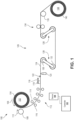
- FIG. 1 is a schematic side view of a system 100 for rapidly quenching and recoiling a hot metal coil 104 according to certain aspects of the present disclosure.
- the hot metal coil 104 comprises metal strip 124 at high temperatures (e.g., temperature at or above the recrystallization temperature of the metal strip 124).
- the metal coil 104 can be unwound by an unwinder 102.
- the unwinder 102 can unwind the hot metal coil 104 in unwinding direction 106.
- a non-contacting hold-down device 108 can apply slight force to facilitate controlled pay-off of the metal strip 124 from the remainder of the metal coil 104.
- the non-contacting hold-down device 108 is a non-contacting hold-down roll that rotates in direction 110 to apply a slight downstream tension in the metal strip 124.
- the metal strip 124 can fall away from the remainder of the metal coil 104 naturally due to gravity, taking a curvature.
- the curvature can be monitored by a sensor 194, such as a distance sensor and/or a camera (e.g., the curvature being sensed via machine vision).
- the sensor 194 can be coupled to a controller 192.
- Controller 192 can use the curvature measurements to make adjustments to system 100, such as by adjusting the pay-off rate of the uncoiler 102. In some cases, adjustments can include manipulating the position of spray headers 114, 116 of one or more of the set of quenching zones 112.
- the uncoiler 102 can include insulation surrounding at least a portion of the metal coil 104 to retain heat within the metal coil 104.
- the uncoiler 102 can include a heater, such as a heated arbor, sufficient to maintain the temperature of the metal strip 124 while the metal strip 124 is in the metal coil 104.
- the uncoiled metal strip 124 can pass through a set of quenching zones 112.
- Each of the set of quenching zones can comprise an upper spray header 114 and a lower spray header 116.
- Each spray header 114, 116 can itself comprise one or more ports through which coolant is directed towards the metal strip.
- the rate of coolant flow can be controlled, such as via controller 192.
- the rate of coolant flow can be sufficient to reduce the temperature of the metal strip 124 by at least 100 °C/s or 200 °C/s.
- the metal strip After passing through the set of quenching zones 112, the metal strip can pass by air knives 118 that blow excess coolant off the top of the metal strip 124.
- an optional squeegee 122 can be used to further remove excess coolant.
- a wiper 120 can be used to remove excess coolant from the bottom of the metal strip 124. In some cases, the wiper 120 is an ultra-compliant wiper.
- the metal strip 124 can pass through a bridle zone 126.
- the metal strip 124 can wrap around upper bridle rolls 130 and lower bridle rolls 132 to impart a desired amount of tension on the metal strip 124 downstream of the bridle zone 126, without imparting additional tension on the metal strip 124 upstream of the bridle zone 126.
- devices other than or in addition to bridle rolls 130, 132 can be used to impart the necessary tension onto the metal strip 124.
- the bridle zone 126 can comprise an easy-thread bridle. As depicted in FIG.
- the bridle zone 126 comprises two bridle arms 128 each coupling an upper bridle roll 130 to a lower bridle roll 132.
- the bridle arms 128 are in an operating position in FIG. 1 .
- bridle arms 128 can be pivoted around the upper bridle rolls 130 such that the lower bridle rolls 132 are positioned above the upper bridle rolls 130.
- the metal strip 124 can be easily passed between the upper bridle rolls 130 and lower bridle rolls 132 (e.g., the metal strip 124 can pass above the upper bridle rolls 130 and below the lower bridle rolls 132).
- the bridle arms 128 can be pivoted again around the upper bridle rolls 130 until the lower bridle rolls 132 fully engage the metal strip 124, as depicted in FIG. 1 .
- the metal strip 124 can optionally pass through a lubricator 134 to apply lubricant to the metal strip 124, such as to lubricate the metal strip 124 in advance of coiling the metal strip 124.
- the metal strip 124 can pass around a deflection roll 136.
- the deflection roll 136 can redirect the metal strip 124 to be appropriately coiled by coiler 134.
- the deflection roll 136 can measure the flatness of the metal strip.
- the deflection roll 136 can be coupled to the controller 192 to facilitate feedback control of the set of quenching zones 112 based on measured flatness at the deflection roll 136.
- the deflection roll 136 can be a flatness measuring roll.
- the metal strip 124 after being cooled and after tension is applied, is coiled into a metal coil 140 by coiler 138.
- the metal coil 140 is a warm or cold coil, at a temperature below the recrystallization temperature of the metal strip 124. In some case, the metal coil 140 is at room temperature. In some cases, the metal coil 140 (e.g., the metal strip 124 after quenching) is at a temperature suitable for warm or cold rolling.
- FIG. 2 is a schematic side view of a system 200 for rapidly quenching a hot metal coil 204 for further rolling according to certain aspects of the present disclosure.
- System 200 can be similar to system 100, although with some different elements and configuration. Certain aspects and features of system 200 can be used with system 100 where appropriate, and certain aspects and features of system 100 can be used with system 200 where appropriate.
- the hot metal coil 204 comprises metal strip 224 at high temperatures (e.g., temperature at or above the recrystallization temperature of the metal strip 224).
- the metal coil 204 can be unwound by an unwinder 202.
- the unwinder 202 can unwind the hot metal coil 204 in unwinding direction 206.
- a non-contacting hold-down device 208 can apply slight force to facilitate controlled pay-off of the metal strip 224 from the remainder of the metal coil 204.
- the non-contacting hold-down device 208 is a non-contacting hold-down roll that rotates in direction 210 to apply a slight downstream tension in the metal strip 224.
- the metal strip 224 can fall away from the remainder of the metal coil 204 naturally due to gravity, taking a curvature.
- the curvature can be monitored by a sensor, as disclosed with reference to system 100 of FIG. 1 .
- a controller can be used to make adjustments to system 200, such as disclosed with reference to system 100 of FIG. 1 .
- the uncoiler 202 can include insulation surrounding at least a portion of the metal coil 204 to retain heat within the metal coil 204.
- the uncoiler 202 can include a heater, such as a heated arbor, sufficient to maintain the temperature of the metal strip 224 while the metal strip 224 is in the metal coil 204.
- the uncoiled metal strip 224 can pass through a set of preheaters 246 before passing through a set of quenching zones 212.
- the preheaters 246 are magnetic rotors that rotate and generate a changing magnetic field through the metal strip 224 sufficient to increase a temperature of the metal strip 224 to a target temperature.
- other types of preheaters 246 can be used, such as direct flame heaters, infrared heaters, hot air blowers, or other heaters.
- the metal strip 224 can be passed through the set of quenching zones 212.
- Each of the set of quenching zones can comprise an upper spray header 214 and a lower spray header 216.
- Each spray header 214, 216 can itself comprise one or more ports through which coolant is directed towards the metal strip.
- the rate of coolant flow can be controlled. The rate of coolant flow can be sufficient to reduce the temperature of the metal strip 224 by at least 100 °C/s or 200 °C/s.
- a steam reclamation module 242 can be positioned adjacent the set of quenching zones 212 to capture steam from areas near one or more of the set of quenching zones and redirect the steam towards the metal strip 224 at a location further downstream.
- the steam reclamation module 242 comprises ductwork configured to capture and redirect steam towards the metal strip 224, however this need not always be the case.
- a steam reclamation module 242 can carry steam away from the metal strip 224, through a blower, and back towards the metal strip 224.
- the steam reclamation module 242 can collect and/or redirect steam away from the metal coil 204 to help prevent staining of the metal strip 224 still on the metal coil 204.
- the metal strip 224 can pass by air knives 218 that blow excess coolant off the top of the metal strip 224.
- an optional squeegee 222 can be used to further remove excess coolant.
- a wiper 220 can be used to remove excess coolant from the bottom of the metal strip 224.
- the wiper 220 can be an ultra-compliant wiper.
- the metal strip 224 can pass through a bridle zone 226.
- the metal strip 224 can wrap around outer bridle rolls 230 and an inner bridle roll 232 to impart a desired amount of tension on the metal strip 224 downstream of the bridle zone 226, without imparting additional tension on the metal strip 224 upstream of the bridle zone 226.
- devices other than or in addition to bridle rolls 230, 232 can be used to impart the necessary tension onto the metal strip 224. As depicted in FIG. 2 , the bridle rolls 230, 232 are in an operating position.
- the inner bridle roll 232 can be raised and the metal strip 224 can be passed above the outer bridle rolls 230 and below the inner bridle roll 232. Then, the inner bridle roll 232 can be moved back down to the position seen in FIG. 2 to engage the metal strip 224 and enter the operating position.
- the metal strip 224 can optionally pass through a lubricator 234 to apply lubricant to the metal strip 224, such as to lubricate the metal strip 224 in advance of rolling the metal strip 224.
- the metal strip 224 can be directed to downstream equipment, such as a roll stack 224 of a rolling mill.
- the downstream equipment can be any suitable downstream equipment, such as downstream equipment that requires an amount of back-tension that is greater than the yield strength of the metal strip 224 at the temperatures of the hot coil 204, or downstream equipment that requires the metal strip 224 be at a temperature below that of the hot coil 204.
- the system 200 can enable a hot coil 204 to be fed into downstream equipment previously unusable with hot coils 204.
- the metal strip 224 entering the downstream equipment is at a warm or cold temperature, such as a temperature below the recrystallization temperature of the metal strip 224.
- the metal coil 240 is at room temperature.
- the metal strip 224 entering the downstream equipment is at a temperature suitable for warm or cold rolling.
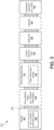
- FIG. 3 is a schematic block diagram of a rapid quench line 300 according to certain aspects of the present disclosure.
- Rapid quench line 300 can be systems 100, 200 of FIGs. 1 , 2 .
- the metal strip 324 moves downstream through the rapid quench line 300, from left-to-right as depicted in FIG. 3 .
- An uncoiler 302 can accept a hot metal coil (e.g., a metal coil at or above recrystallization temperature) and uncoil the metal strip 324 from the hot coil with low tension.
- the uncoiler 302 can rely on gravity to pay-off the metal strip 324.
- the uncoiler 302 can include a non-contacting hold-down device 308 suitable to apply force to the metal coil to facilitate pay-off of the metal strip 324.
- An optional non-contacting heater 346 can be positioned downstream of the uncoiler 302.
- the non-contacting heater 346 e.g., preheater, such as preheater 246 of FIG. 2
- the non-contacting heater 346 can be any suitable device for heating the metal strip 324 prior to quenching, such as a magnetic rotor heater.
- a magnetic rotor heater can comprise a set of permanent magnets disposed on a rotor, which, when spun, can impart a temperature increase on an adjacent metal strip.
- a set of quenching zones 312 can be positioned downstream of the uncoiler 302 and optional non-contacting heater 346.
- Each quenching zone can comprise one or more spray headers positioned to dispense coolant on the metal strip 324.
- an optional steam reclamation module 342 can be positioned to collect steam from one or more of the set of quenching zones and redirect the steam towards the metal strip 324 to facilitate cooling the metal strip 324, especially when the temperature of the metal strip 324 is at or below the Leidenfrost point.
- a coolant removal zone 318 can be positioned downstream of the set of quenching zones.
- the coolant removal zone 318 can comprise any equipment suitable for removing coolant from the metal strip 324.
- the coolant removal zone 318 can comprise one or more air knives.
- the coolant removal zone 318 can comprise one or more squeegees.
- the coolant removal zone 318 can comprise one or more wipers (e.g., ultra-compliant wipers).
- a bridle zone 326 can be positioned downstream of the coolant removal zone 318.
- the bridle zone 326 can comprise a set of bridle rolls about which the metal strip 324 can be partially wrapped to achieve a downstream tension in the metal strip 324 (e.g., a tension downstream of the bridle zone 326).
- the bridle zone 326 can comprise easy-threading bridle rolls.
- an optional lubricator 334 can be positioned downstream of the bridle zone 326 to impart lubrication on the metal strip prior to reaching the downstream equipment 338.
- the metal strip 324 can reach downstream equipment 338 for further processing or storage.
- the downstream equipment 338 can comprise a coiler.
- the downstream equipment 338 can comprise other equipment, such as warm or cold rolling mills.
- FIG. 4 is a combination schematic block diagram 400 and temperature graph 401 depicting relative temperatures of a metal strip 424 passing through a rapid quench line according to certain aspects of the present disclosure.
- the metal strip 424 moves downstream through the rapid quench line, from left-to-right as depicted in FIG. 4 .
- Block diagram 400 can be a diagram of the rapid quench line 300 of FIG. 3 .
- the temperature graph 401 is a relative graph for illustrative purposes only and is not intended to be to scale.
- the block diagram 400 and temperature graph 401 are vertically aligned to depict the approximate relative temperatures of the metal strip 424 as it passes through the various components of the rapid quench line depicted in the block diagram 400.
- the metal strip 424 can have a temperature that is considered hot, such as a temperature at or above the recrystallization temperature 457 of the metal strip 424.
- the uncoiler 402 can receive a hot coil at various initial temperatures 450.
- integrated heating and/or insulation in the uncoiler 402 can help maintain the initial temperature 450 of the metal strip 424.
- an optional non-contacting heater 446 can impart additional heating designed to raise the temperature of the metal strip 424 to a target temperature 456, despite the initial temperature 450 of the hot coil.
- the non-contacting hold-down device 408 can impart some amount of heat into the metal strip 424, although that need not be the case.
- the steam reclamation module 442 can collect steam from upstream quenching zone(s), such as first quenching zone 458 and second quenching zone 460, and redirect the steam and/or humid air towards the metal strip 424 at a location downstream of where the steam was collected.
- the steam reclamation module 442 can redirect the steam towards the metal strip 424 before, during, or after subsequent quenching zones (e.g., third quenching zone 462 and fourth quenching zone 464). In some cases, the steam reclamation module 442 can redirect the steam towards the metal strip 424 at a location 468 where the metal strip 424 is about to, is currently, or has already dropped below the Leidenfrost point 470.
- the temperature of the metal strip 424 can be at a warm or cold temperature.
- the temperature of the metal strip 424 may not change significantly after the set of quenching zones 412, such as when passing through the coolant removal zone 418, bridle zone 426, optional lubricator 434, or downstream equipment 438; although in some cases the temperature of the metal strip 424 may slowly approach room temperature or ambient temperature.
- the temperature of the metal strip 424 after the set of quenching zones 412 can be known as a cooled temperature 472.
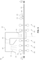
- FIG. 5 is a schematic side view of a steam reclamation module 542 on a rapid quench line 500 according to certain aspects of the present disclosure.
- FIG. 5 depicts a portion of a rapid quench line 500 located between an uncoiler and a bridle zone.
- the rapid quench line 500 can be rapid quench line 300 of FIG. 3 .
- the metal strip 524 can pass through several quenching zones 558, 560, 562, 564, 566.
- Each quenching zone can comprise spray headers 514 that dispense coolant 574 onto the metal strip 524. Coolant extract heat from the metal strip 524, especially near the first one, two, or several quenching zones (e.g., quenching zones 558, 560, 562) will generate a substantial amount of steam 576.
- a steam reclamation module 542 can be positioned to capture steam 576 and redirect the steam 576 back onto the metal strip 524.
- the steam reclamation module 542 can comprise a hood 578 for collecting the steam and ductwork 580 for redirecting the steam towards the metal strip 524.
- the steam reclamation module 542 can comprise an optional blower 582 that facilitates moving the steam 576 towards the metal strip 524 (e.g., towards the end of the ductwork 580 opposite the hood 578.
- the steam reclamation module 542 redirects the steam 576 back to the metal strip 524 at a location downstream of the first three quenching zones 558, 560, 562 and upstream of the last two quenching zones 564, 566, although this need not always be the case.
- the steam reclamation module 542 can instead redirect steam 576 to the metal strip 524 at any suitable location, including upstream or downstream of the location where the steam 576 is collected. However, it has been determined that redirecting steam 576 to the metal strip 524 adjacent to, at, and/or immediately after a location 568 where the temperature of the metal strip 524 is at or below the Leidenfrost point can be especially useful.
- FIG. 5 Also depicted in FIG. 5 is a set of air knives 518 positioned above the metal strip 524 to direct air 584 onto the surface of the metal strip 524 to remove coolant from the metal strip 524.
- FIG. 6 is a schematic top view of a non-contacting hold-down roll 608 comprising a magnetic rotor 690 according to certain aspects of the present disclosure.
- the non-contacting hold-down roll 608 can be a magnetic rotor 690. While any suitable magnetic rotor can be used, it has been determined that a magnetic rotor 690 with a chevron pattern of magnetic poles can be especially suitable for imparting consistent (e.g., non-fluctuating) tension on the metal strip, thus minimizing the risk of damaging the fragile hot coil.
- the chevron pattern depicted in FIG. 6 shows alternating north poles 686 and south poles 688 distributed across the width and circumference of the magnetic rotor 690.
- the chevron pattern is configured such that for all points along the rotation of the magnetic rotor 690, the magnetic rotor 690 will always be presenting at or approximately the same amount of magnetic flux to the metal strip.
- the chevron pattern can vary in overlap, gap, angle of attack, and other characteristics.
- the magnetic rotor 690 is configured to rotate in the direction of the chevron patter (e.g., from the top of the page to the bottom of the page as depicted in FIG. 6 ), although that need not always be the case.
- other types of patterns are used to achieve a consistent tension on the metal strip.
- FIG. 7 is a flowchart depicting a process 700 for rapidly quenching a hot metal coil according to certain aspects of the present disclosure.
- process 700 can use the systems 100, 200 of FIGs. 1 , 2 or the rapid quench line 300 of FIG. 3 .
- hot metal coil is unwound. Unwinding of the hot metal coil is performed by a low-tension unwinder. In some cases, unwinding the hot metal coil further comprises applying non-contacting hold-down force to the metal coil through a non-contacting hold-down device. In some cases, unwinding the hot metal coil comprises permitting the metal strip to pay-off from the metal coil through the use of gravity.
- the metal strip can be heated (e.g., preheated) to a target temperature. In some cases, if the hot metal coil is already at the target temperature, not preheating is necessary.
- the metal strip can be rapidly quenched. Rapid quenching can comprise lowering the temperature of the metal strip at a rate of at or at least 100 °C/s or 200 °C/s. Rapid quenching can involve dispensing coolant to the metal strip using one or more spray headers. In some cases, rapidly quenching the metal strip at block 708 can further include one or more of optional blocks 710, 712, 714.
- steam from one or more quenching zones can be collected.
- the metal strip can be quenched to a temperature below the Leidenfrost point.
- steam collected from block 710 can be redirected to the metal strip. In some cases, block 714 can occur without block 712 first occurring. However, in some cases, block 714 occurs only after the metal strip has reached a temperature below the Leidenfrost point at block 712.
- quenching the metal strip at block 708 can comprise receiving flatness information (e.g., from a downstream flatness measurement device, such as a deflection roll) and adjusting the dispensing of coolant from the spray headers to achieve a desired flatness.
- flatness information e.g., from a downstream flatness measurement device, such as a deflection roll
- coolant is removed from the metal strip.
- removing coolant from the metal strip can comprise using any combination of air knives, squeegees, wipers (e.g., ultra-compliant wipers), or other coolant-removing devices.
- Tension applied to the metal strip at block 718 can be downstream tension, such that the tension does not carry up through the hot roll at the uncoiler, but rather carries through to the downstream equipment. Applying tension at block 718 can comprise passing the metal strip through bridle rolls of a bridle zone to impart tension into the metal strip.
- lubrication can be optionally applied to the metal strip.
- the metal strip can proceed downstream to any suitable downstream equipment.
- the downstream equipment can be a coiler, in which case the metal strip can be coiled at block 722.
- the resultant metal coil will be a warm metal coil or a cold metal coil.
- other downstream equipment may be used, in which case the metal strip may undergo other downstream processing, such as warm rolling or cold rolling.
- Illustration 1 is a system, comprising: a low-tension unwinding unit for receiving and unwinding a metal coil of metal strip; a non-contacting hold-down device positioned adjacent the low-tension unwinding unit to provide force on the metal strip towards the center of the metal coil during unwinding of the metal coil; a set of quenching zones for cooling the metal strip, wherein the set of quenching zones provides sufficient coolant to reduce a temperature of the metal strip by a rate of at least 100 °C per second; a coolant removal unit positioned downstream of the set of quenching zones; and a bridle unit positioned downstream of the coolant removal unit for increasing tension in the metal strip.
- Illustration 2 is the system of any preceding or subsequent illustration or combination of illustrations, wherein the low-tension unwinding unit comprises insulation disposed to retain heat within coiled portions of the metal coil.
- Illustration 3 is the system of any preceding or subsequent illustration or combination of illustrations, wherein the low-tension unwinding unit comprises a heat source for providing heat to coiled portions of the metal coil, wherein the heat source is coupled to a controller for maintaining the metal coil at or above a threshold temperature.
- the low-tension unwinding unit comprises a heat source for providing heat to coiled portions of the metal coil, wherein the heat source is coupled to a controller for maintaining the metal coil at or above a threshold temperature.
- Illustration 4 is the system of any preceding or subsequent illustration or combination of illustrations, wherein the non-contacting hold-down device comprises one or more magnets for generating a changing magnetic field through the metal strip.
- Illustration 5 is the system of any preceding or subsequent illustration or combination of illustrations, wherein the changing magnetic field is configured distribute the force over time across a width of the metal strip.
- Illustration 6 is the system of any preceding or subsequent illustration or combination of illustrations, wherein the non-contacting hold-down device comprises a nozzle for blowing heated air against the metal strip.
- Illustration 7 is the system of any preceding or subsequent illustration or combination of illustrations, further comprising: a flatness measurement unit positioned to measure a flatness of the metal strip; and a controller coupled to the flatness measurement unit and the set of quenching zones to adjust delivery of the coolant based on measured flatness of the metal strip.
- Illustration 8 is the system of any preceding or subsequent illustration or combination of illustrations, further comprising a stabilization system positioned upstream of the set of quenching zones to introduce a wave into the metal strip.
- Illustration 9 is the system of any preceding or subsequent illustration or combination of illustrations, wherein the metal strip remains supported without mechanical contact between the metal coil and the coolant removal unit.
- Illustration 10 is the system of any preceding or subsequent illustration or combination of illustrations, wherein the set of quenching zones comprises a steam reclamation module for redirecting humid air from at least one of the set of quenching zones to the metal strip at a location downstream of the at least one of the set of quenching zones.
- the set of quenching zones comprises a steam reclamation module for redirecting humid air from at least one of the set of quenching zones to the metal strip at a location downstream of the at least one of the set of quenching zones.
- Illustration 11 is the system of any preceding or subsequent illustration or combination of illustrations, wherein the location downstream of the at least one of the set of quenching zones is a location where the temperature of the metal strip is at or below a Leidenfrost point.
- Illustration 12 is the system of any preceding or subsequent illustration or combination of illustrations, further comprising: a pre-quench heating unit positioned downstream of the low-tension unwinding unit; and a controller coupled to the pre-quench heating unit to heat the metal strip to a target temperature prior to the metal strip entering the set of quenching zones.
- Illustration 13 is the system of any preceding or subsequent illustration or combination of illustrations, wherein the non-contacting hold-down device is positioned to provide the force on the metal strip at a location at or adjacent to where the metal strip falls away from the metal coil due to gravity.
- Illustration 14 is a method, comprising: unwinding a hot metal coil using a low-tension unwinder, wherein unwinding the hot metal coil comprises applying a non-contacting hold-down force to the hot metal coil and permitting metal strip of the hot metal coil to fall away from the metal coil; rapidly quenching the metal strip in a set of quenching zones, wherein rapidly quenching the metal strip comprises applying coolant to the metal strip to reduce a temperature of the metal strip at a rate of at least 100 °C per second; removing the coolant from the metal strip; and applying downstream tension to the metal strip.
- Illustration 15 is the method of any preceding or subsequent illustration or combination of illustrations, further comprising maintaining an initial temperature of the hot metal coil at the low-tension unwinder.
- Illustration 16 is the method of any preceding or subsequent illustration or combination of illustrations, further comprising preheating the metal strip immediately prior to rapidly quenching the metal strip.
- Illustration 17 is the method of any preceding or subsequent illustration or combination of illustrations, wherein applying the non-contacting hold-down force comprises generating a changing magnetic field through the metal strip.
- Illustration 18 is the method of any preceding or subsequent illustration or combination of illustrations, wherein applying the non-contacting hold-down force comprises blowing heated air against the metal strip.
- Illustration 19 is the method of any preceding or subsequent illustration or combination of illustrations, further comprising: measuring flatness of the metal strip; and adjusting delivery of the coolant based on the measured flatness.
- Illustration 20 is the method of any preceding or subsequent illustration or combination of illustrations, further comprising inducing a wave in the metal strip without contacting the metal strip.
- Illustration 21 is the method of any preceding or subsequent illustration or combination of illustrations, further comprising: capturing steam from at least one of the quenching zones; and redirecting the captured steam towards the metal strip.
- Illustration 22 is the method of any preceding or subsequent illustration or combination of illustrations, wherein redirecting the captured steam comprises redirecting the capture steam towards the metal strip at a location where a temperature of the metal strip is at or below the Leidenfrost point.
Landscapes
- Chemical & Material Sciences (AREA)
- Engineering & Computer Science (AREA)
- Mechanical Engineering (AREA)
- Materials Engineering (AREA)
- Crystallography & Structural Chemistry (AREA)
- Thermal Sciences (AREA)
- Physics & Mathematics (AREA)
- Metallurgy (AREA)
- Organic Chemistry (AREA)
- Heat Treatment Of Strip Materials And Filament Materials (AREA)
- Winding, Rewinding, Material Storage Devices (AREA)
- Metal Rolling (AREA)
- Superconductors And Manufacturing Methods Therefor (AREA)
- Glass Compositions (AREA)
- Insulated Conductors (AREA)
Claims (15)
- System, umfassend:eine Abwickeleinheit mit niedriger Spannung zum Aufnehmen und Abwickeln einer Metallspule aus Metallband;eine berührungslose Niederhaltevorrichtung, die neben der Abwickeleinheit mit niedriger Spannung so angeordnet ist, dass sie während des Abwickelns der Metallspule Kraft auf das Metallband in Richtung der Mitte der Metallspule ausübt;einen Satz an Abschreckzonen zum Kühlen des Metallbandes, wobei der Satz an Abschreckzonen ausreichend Kühlmittel bereitstellt, um eine Temperatur des Metallbandes um eine Rate von mindestens 30 °C pro Sekunde zu reduzieren;eine Einheit zum Entfernen von Kühlmittel, die stromabwärts des Satzes an Abschreckzonen angeordnet ist; undeine Brückeneinheit, die stromabwärts der Einheit zum Entfernen von Kühlmittel angeordnet ist, um Spannung in dem Metallband zu erhöhen.
- System nach Anspruch 1, wobei die Abwickeleinheit mit niedriger Spannung eine Isolierung umfasst, die so angeordnet ist, dass sie Wärme innerhalb aufgewickelter Abschnitte der Metallspule zurückhält und/oder eine Wärmequelle, um aufgewickelte Abschnitte der Metallspule mit Wärme zu versorgen, wobei die Wärmequelle mit einem Regler verbunden ist, um die Metallspule bei oder über einer Schwellentemperatur zu halten.
- System nach Anspruch 1 oder 2, wobei die berührungslose Niederhaltevorrichtung einen oder mehrere Magnete zum Erzeugen eines sich ändernden Magnetfeldes durch das Metallband umfasst, wobei das sich ändernde Magnetfeld vorzugsweise dazu konfiguriert ist, die Kraft im Laufe der Zeit über eine Breite des Metallbandes zu verteilen.
- System nach einem der Ansprüche 1 bis 3, wobei die berührungslose Niederhaltevorrichtung eine Düse zum Blasen von erwärmter Luft gegen das Metallband umfasst.
- System nach einem der Ansprüche 1 bis 4, ferner umfassend:eine Einheit zum Messen der Flachheit, die so angeordnet ist, dass sie eine Flachheit des Metallbandes misst; undeinen Regler, der mit der Einheit zum Messen der Flachheit und dem Satz an Abschreckzonen gekoppelt ist, um eine Zufuhr des Kühlmittels auf der Grundlage gemessener Flachheit des Metallbandes einzustellen.
- System nach einem der Ansprüche 1 bis 5, ferner umfassend ein Stabilisierungssystem, das stromaufwärts von dem Satz an Abschreckzonen angeordnet ist, um eine Welle in das Metallband einzubringen, und/oder wobei das Metallband ohne mechanischen Kontakt zwischen der Metallspule und der Einheit zum Entfernen von Kühlmittel weiterhin gehalten wird.
- System nach einem der Ansprüche 1 bis 6, wobei der Satz von Abschreckzonen ein Dampfrückgewinnungsmodul umfasst, um feuchte Luft aus mindestens einem Satz an Abschreckzonen zu dem Metallband an einer Stelle stromabwärts des mindestens einen Satzes an Abschreckzonen umzuleiten, und/oder wobei die Stelle stromabwärts des mindestens einen Satzes an Abschreckzonen eine Stelle ist, an der die Temperatur des Metallbandes bei oder unter einem Leidenfrost-Punkt liegt.
- System nach einem der Ansprüche 1 bis 7, ferner umfassend:eine Vorabschreckheizeinheit, die stromabwärts der Abwickeleinheit mit niedriger Spannung angeordnet ist; undeinen Regler, der mit der Vorabschreckheizeinheit gekoppelt ist, um das Metallband auf eine Zieltemperatur zu erwärmen, bevor das Metallband in den Satz an Abschreckzonen eintritt.
- System nach einem der Ansprüche 1 bis 8, wobei die berührungslose Niederhaltevorrichtung so angeordnet ist, dass sie die Kraft auf das Metallband an einer Stelle oder in der Nähe einer Stelle ausübt, an der das Metallband aufgrund von Schwerkraft von der Metallspule abfällt.
- Verfahren, umfassend:Abwickeln einer heißen Metallspule unter Verwendung eines Abwicklers mit niedriger Spannung, wobei Abwickeln der heißen Metallspule Aufbringen einer berührungslosen Niederhaltekraft auf die heiße Metallspule und Zulassen, dass das Metallband der heißen Metallspule von der Metallspule abfällt, umfasst;schnelles Abschrecken des Metallbandes in einem Satz von Abschreckzonen, wobei schnelles Abschrecken des Metallbandes Aufbringen von Kühlmittel auf das Metallband umfasst, um eine Temperatur des Metallbandes mit einer Rate von mindestens 100 °C pro Sekunde zu verringern;Entfernen des Kühlmittels von dem Metallband, undAufbringen einer stromabwärts-gerichteten Spannung auf das Metallband.
- Verfahren nach Anspruch 10, ferner umfassend Aufrechterhalten einer Anfangstemperatur der heißen Metallspule an dem Abwickler mit niedriger Spannung und/oder Vorheizen des Metallbandes unmittelbar vor einem schnellen Abschrecken des Metallbandes.
- Verfahren nach Anspruch 10 oder 11, wobei Aufbringen der berührungslosen Niederhaltekraft Erzeugen eines sich ändernden Magnetfeldes durch das Metallband und/oder Blasen erwärmter Luft gegen das Metallband umfasst.
- Verfahren nach einem der Ansprüche 10 bis 12, ferner umfassend:Messen der Flachheit des Metallbandes; undEinstellen einer Zufuhr des Kühlmittels auf der Grundlage der gemessenen Flachheit.
- Verfahren nach einem der Ansprüche 10 bis 13, ferner umfassend Erzeugen einer Welle in dem Metallband ohne das Metallband zu berühren.
- Verfahren nach einem der Ansprüche 10 bis 14, ferner umfassend:Auffangen von Dampf aus mindestens einer der Abschreckzonen; undUmlenken des aufgefangenen Dampfes in Richtung des Metallbandes,wobei Umlenken des aufgefangenen Dampfes vorzugsweise Umlenken des aufgefangenen Dampfes in Richtung des Metallbandes an einer Stelle umfasst, an der eine Temperatur des Metallbandes bei oder unter einem Leidenfrost-Punkt liegt.
Applications Claiming Priority (2)
| Application Number | Priority Date | Filing Date | Title |
|---|---|---|---|
| US201962915915P | 2019-10-16 | 2019-10-16 | |
| PCT/US2020/055327 WO2021076473A1 (en) | 2019-10-16 | 2020-10-13 | Rapid quench line |
Publications (2)
| Publication Number | Publication Date |
|---|---|
| EP4045203A1 EP4045203A1 (de) | 2022-08-24 |
| EP4045203B1 true EP4045203B1 (de) | 2023-11-29 |
Family
ID=73060086
Family Applications (1)
| Application Number | Title | Priority Date | Filing Date |
|---|---|---|---|
| EP20801073.6A Active EP4045203B1 (de) | 2019-10-16 | 2020-10-13 | Schnelle quench-leitung |
Country Status (10)
| Country | Link |
|---|---|
| US (1) | US20220349038A1 (de) |
| EP (1) | EP4045203B1 (de) |
| JP (1) | JP7378609B2 (de) |
| KR (1) | KR102713821B1 (de) |
| CN (1) | CN114585753B (de) |
| BR (1) | BR112022005740A2 (de) |
| CA (1) | CA3152277C (de) |
| ES (1) | ES2967375T3 (de) |
| MX (1) | MX2022004453A (de) |
| WO (1) | WO2021076473A1 (de) |
Families Citing this family (3)
| Publication number | Priority date | Publication date | Assignee | Title |
|---|---|---|---|---|
| EP3827903A1 (de) * | 2019-11-29 | 2021-06-02 | Cockerill Maintenance & Ingenierie S.A. | Vorrichtung und verfahren zur herstellung eines beschichteten metallbandes mit verbessertem aussehen |
| CN115074514A (zh) * | 2022-07-25 | 2022-09-20 | 西安钢研功能材料股份有限公司 | 一种软磁合金1j22带材连续淬火的制备方法 |
| CN119634448B (zh) * | 2024-12-17 | 2025-12-05 | 邯郸钢铁集团有限责任公司 | 一种延长卷取机芯轴寿命的控制方法 |
Family Cites Families (18)
| Publication number | Priority date | Publication date | Assignee | Title |
|---|---|---|---|---|
| US2887422A (en) * | 1950-02-25 | 1959-05-19 | United Eng Foundry Co | Method of continuously heat treating aluminum strip |
| CA948530A (en) * | 1969-12-30 | 1974-06-04 | Bunichiro Kawasaki | Method and apparatus for producing low carbon cold-rolled steel |
| US4016740A (en) * | 1973-12-27 | 1977-04-12 | Nippon Steel Corporation | Method and an apparatus for the manufacture of a steel sheet |
| US4019359A (en) * | 1974-05-06 | 1977-04-26 | The Steel Company Of Canada, Limited | Method of hot rolling metal strip |
| US5121902A (en) * | 1984-10-09 | 1992-06-16 | Morgan Construction Company | Apparatus for cooling hot rolled steel rod using a plurality of air and water cooled sections |
| AU3488293A (en) * | 1992-02-24 | 1993-09-13 | Alcan International Limited | Process and apparatus for applying and removing liquid coolant to control temperature of continuously moving metal strip |
| US5753894A (en) * | 1993-06-15 | 1998-05-19 | Kawasaki Steel Corporation | Hot rolling method for continuously joining metal blocks and an apparatus for the same |
| JP3066379B2 (ja) * | 1994-05-26 | 2000-07-17 | 新日本製鐵株式会社 | コイルオープナー用マグネットコンベア |
| CN101376212B (zh) * | 2007-08-29 | 2010-10-13 | 烨联钢铁股份有限公司 | 以白皮钢卷产制产品钢卷的冷轧连续生产线 |
| DE102009023359A1 (de) * | 2008-08-18 | 2010-02-25 | Sms Siemag Ag | Verfahren und Vorrichtung zur Kühlung und Trocknung eines Warmbandes oder eines Bleches in einem Walzwerk |
| CN107735188B (zh) * | 2015-06-09 | 2020-08-18 | 诺维尔里斯公司 | 非接触磁性转向 |
| US11142815B2 (en) * | 2015-07-07 | 2021-10-12 | Arconic Technologies Llc | Methods of off-line heat treatment of non-ferrous alloy feedstock |
| CA2991618C (en) * | 2015-07-07 | 2020-01-28 | Arconic Technologies Llc | Methods of off-line heat treatment of non-ferrous alloy feedstock |
| MX370035B (es) * | 2016-09-27 | 2019-11-28 | Novelis Inc | Sistema y metodo para el roscado de un sustrato de metal en un tren de laminacion. |
| WO2018062375A1 (ja) * | 2016-09-29 | 2018-04-05 | 日立金属株式会社 | 金属条コイルおよびその製造方法 |
| KR20220071291A (ko) * | 2017-01-11 | 2022-05-31 | 아르코닉 테크놀로지스 엘엘씨 | 접합용 알루미늄 합금 제품 제조 방법 |
| JP7016723B2 (ja) * | 2017-03-15 | 2022-02-07 | 株式会社神戸製鋼所 | 鋼板冷却方法 |
| EP3406744A1 (de) * | 2017-05-23 | 2018-11-28 | Läpple Automotive GmbH | Blechbearbeitungsanlage und verfahren zur herstellung eines blechbauteils |
-
2020
- 2020-10-13 WO PCT/US2020/055327 patent/WO2021076473A1/en not_active Ceased
- 2020-10-13 EP EP20801073.6A patent/EP4045203B1/de active Active
- 2020-10-13 CA CA3152277A patent/CA3152277C/en active Active
- 2020-10-13 ES ES20801073T patent/ES2967375T3/es active Active
- 2020-10-13 MX MX2022004453A patent/MX2022004453A/es unknown
- 2020-10-13 JP JP2022522737A patent/JP7378609B2/ja active Active
- 2020-10-13 BR BR112022005740A patent/BR112022005740A2/pt not_active Application Discontinuation
- 2020-10-13 US US17/766,091 patent/US20220349038A1/en not_active Abandoned
- 2020-10-13 KR KR1020227011939A patent/KR102713821B1/ko active Active
- 2020-10-13 CN CN202080072098.5A patent/CN114585753B/zh active Active
Also Published As
| Publication number | Publication date |
|---|---|
| KR20220062364A (ko) | 2022-05-16 |
| ES2967375T3 (es) | 2024-04-30 |
| CA3152277C (en) | 2024-10-22 |
| JP2022552979A (ja) | 2022-12-21 |
| CN114585753B (zh) | 2024-05-14 |
| MX2022004453A (es) | 2022-05-03 |
| CN114585753A (zh) | 2022-06-03 |
| US20220349038A1 (en) | 2022-11-03 |
| KR102713821B1 (ko) | 2024-10-11 |
| CA3152277A1 (en) | 2021-04-22 |
| BR112022005740A2 (pt) | 2022-06-21 |
| WO2021076473A1 (en) | 2021-04-22 |
| EP4045203A1 (de) | 2022-08-24 |
| JP7378609B2 (ja) | 2023-11-13 |
Similar Documents
| Publication | Publication Date | Title |
|---|---|---|
| EP4045203B1 (de) | Schnelle quench-leitung | |
| CN109792806B (zh) | 使用磁加热的预时效系统和方法 | |
| ES2955353T3 (es) | Método de colada continua y laminación aleación de aluminio y aleación de aluminio producto intermedio | |
| CA2960321C (en) | Method of annealing aluminium alloy sheet material | |
| KR102018370B1 (ko) | 열간 압연 이전에 강 스톡을 제조하는 방법 및 장치 | |
| US8945319B2 (en) | Manufacturing method and manufacturing apparatus of hot-rolled steel sheet | |
| US6743309B2 (en) | Method and apparatus for casting, hot rolling and annealing non-heat treatment aluminum alloys | |
| CA2613975C (en) | Method and production line for manufacturing metal strips made of copper or copper alloys | |
| CN101678414B (zh) | 热轧装置 | |
| CN101484593B (zh) | 基于薄板坯生产硅钢热轧带轧制材料的方法和设备 | |
| US20120305212A1 (en) | Process and device for producing hot-rolled strip from silicon steel | |
| EP4422811B1 (de) | System zur schnellen substratkühlung | |
| EP4126407B1 (de) | Heissabhaspeln von metall | |
| JP3527819B2 (ja) | 熱延鋼帯の製造方法 | |
| RU2371486C1 (ru) | Способ производства черной жести | |
| JPWO2021076473A5 (de) | ||
| JP2003145203A (ja) | 熱延鋼帯の製造方法 |
Legal Events
| Date | Code | Title | Description |
|---|---|---|---|
| STAA | Information on the status of an ep patent application or granted ep patent |
Free format text: STATUS: UNKNOWN |
|
| STAA | Information on the status of an ep patent application or granted ep patent |
Free format text: STATUS: THE INTERNATIONAL PUBLICATION HAS BEEN MADE |
|
| PUAI | Public reference made under article 153(3) epc to a published international application that has entered the european phase |
Free format text: ORIGINAL CODE: 0009012 |
|
| STAA | Information on the status of an ep patent application or granted ep patent |
Free format text: STATUS: REQUEST FOR EXAMINATION WAS MADE |
|
| 17P | Request for examination filed |
Effective date: 20220512 |
|
| AK | Designated contracting states |
Kind code of ref document: A1 Designated state(s): AL AT BE BG CH CY CZ DE DK EE ES FI FR GB GR HR HU IE IS IT LI LT LU LV MC MK MT NL NO PL PT RO RS SE SI SK SM TR |
|
| DAV | Request for validation of the european patent (deleted) | ||
| DAX | Request for extension of the european patent (deleted) | ||
| GRAP | Despatch of communication of intention to grant a patent |
Free format text: ORIGINAL CODE: EPIDOSNIGR1 |
|
| STAA | Information on the status of an ep patent application or granted ep patent |
Free format text: STATUS: GRANT OF PATENT IS INTENDED |
|
| INTG | Intention to grant announced |
Effective date: 20230606 |
|
| P01 | Opt-out of the competence of the unified patent court (upc) registered |
Effective date: 20230804 |
|
| GRAS | Grant fee paid |
Free format text: ORIGINAL CODE: EPIDOSNIGR3 |
|
| GRAA | (expected) grant |
Free format text: ORIGINAL CODE: 0009210 |
|
| STAA | Information on the status of an ep patent application or granted ep patent |
Free format text: STATUS: THE PATENT HAS BEEN GRANTED |
|
| AK | Designated contracting states |
Kind code of ref document: B1 Designated state(s): AL AT BE BG CH CY CZ DE DK EE ES FI FR GB GR HR HU IE IS IT LI LT LU LV MC MK MT NL NO PL PT RO RS SE SI SK SM TR |
|
| REG | Reference to a national code |
Ref country code: GB Ref legal event code: FG4D |
|
| REG | Reference to a national code |
Ref country code: CH Ref legal event code: EP |
|
| REG | Reference to a national code |
Ref country code: DE Ref legal event code: R096 Ref document number: 602020022038 Country of ref document: DE |
|
| REG | Reference to a national code |
Ref country code: NO Ref legal event code: T2 Effective date: 20231129 |
|
| REG | Reference to a national code |
Ref country code: IE Ref legal event code: FG4D |
|
| REG | Reference to a national code |
Ref country code: SE Ref legal event code: TRGR |
|
| REG | Reference to a national code |
Ref country code: LT Ref legal event code: MG9D |
|
| REG | Reference to a national code |
Ref country code: NL Ref legal event code: MP Effective date: 20231129 |
|
| PG25 | Lapsed in a contracting state [announced via postgrant information from national office to epo] |
Ref country code: GR Free format text: LAPSE BECAUSE OF FAILURE TO SUBMIT A TRANSLATION OF THE DESCRIPTION OR TO PAY THE FEE WITHIN THE PRESCRIBED TIME-LIMIT Effective date: 20240301 |
|
| PG25 | Lapsed in a contracting state [announced via postgrant information from national office to epo] |
Ref country code: IS Free format text: LAPSE BECAUSE OF FAILURE TO SUBMIT A TRANSLATION OF THE DESCRIPTION OR TO PAY THE FEE WITHIN THE PRESCRIBED TIME-LIMIT Effective date: 20240329 |
|
| PG25 | Lapsed in a contracting state [announced via postgrant information from national office to epo] |
Ref country code: LT Free format text: LAPSE BECAUSE OF FAILURE TO SUBMIT A TRANSLATION OF THE DESCRIPTION OR TO PAY THE FEE WITHIN THE PRESCRIBED TIME-LIMIT Effective date: 20231129 |
|
| REG | Reference to a national code |
Ref country code: DE Ref legal event code: R082 Ref document number: 602020022038 Country of ref document: DE Representative=s name: WEICKMANN & WEICKMANN PATENT- UND RECHTSANWAEL, DE |
|
| PG25 | Lapsed in a contracting state [announced via postgrant information from national office to epo] |
Ref country code: LT Free format text: LAPSE BECAUSE OF FAILURE TO SUBMIT A TRANSLATION OF THE DESCRIPTION OR TO PAY THE FEE WITHIN THE PRESCRIBED TIME-LIMIT Effective date: 20231129 Ref country code: IS Free format text: LAPSE BECAUSE OF FAILURE TO SUBMIT A TRANSLATION OF THE DESCRIPTION OR TO PAY THE FEE WITHIN THE PRESCRIBED TIME-LIMIT Effective date: 20240329 Ref country code: GR Free format text: LAPSE BECAUSE OF FAILURE TO SUBMIT A TRANSLATION OF THE DESCRIPTION OR TO PAY THE FEE WITHIN THE PRESCRIBED TIME-LIMIT Effective date: 20240301 Ref country code: BG Free format text: LAPSE BECAUSE OF FAILURE TO SUBMIT A TRANSLATION OF THE DESCRIPTION OR TO PAY THE FEE WITHIN THE PRESCRIBED TIME-LIMIT Effective date: 20240229 |
|
| REG | Reference to a national code |
Ref country code: ES Ref legal event code: FG2A Ref document number: 2967375 Country of ref document: ES Kind code of ref document: T3 Effective date: 20240430 |
|
| PG25 | Lapsed in a contracting state [announced via postgrant information from national office to epo] |
Ref country code: NL Free format text: LAPSE BECAUSE OF FAILURE TO SUBMIT A TRANSLATION OF THE DESCRIPTION OR TO PAY THE FEE WITHIN THE PRESCRIBED TIME-LIMIT Effective date: 20231129 |
|
| PG25 | Lapsed in a contracting state [announced via postgrant information from national office to epo] |
Ref country code: RS Free format text: LAPSE BECAUSE OF FAILURE TO SUBMIT A TRANSLATION OF THE DESCRIPTION OR TO PAY THE FEE WITHIN THE PRESCRIBED TIME-LIMIT Effective date: 20231129 Ref country code: PL Free format text: LAPSE BECAUSE OF FAILURE TO SUBMIT A TRANSLATION OF THE DESCRIPTION OR TO PAY THE FEE WITHIN THE PRESCRIBED TIME-LIMIT Effective date: 20231129 Ref country code: NL Free format text: LAPSE BECAUSE OF FAILURE TO SUBMIT A TRANSLATION OF THE DESCRIPTION OR TO PAY THE FEE WITHIN THE PRESCRIBED TIME-LIMIT Effective date: 20231129 Ref country code: LV Free format text: LAPSE BECAUSE OF FAILURE TO SUBMIT A TRANSLATION OF THE DESCRIPTION OR TO PAY THE FEE WITHIN THE PRESCRIBED TIME-LIMIT Effective date: 20231129 Ref country code: HR Free format text: LAPSE BECAUSE OF FAILURE TO SUBMIT A TRANSLATION OF THE DESCRIPTION OR TO PAY THE FEE WITHIN THE PRESCRIBED TIME-LIMIT Effective date: 20231129 |
|
| PG25 | Lapsed in a contracting state [announced via postgrant information from national office to epo] |
Ref country code: DK Free format text: LAPSE BECAUSE OF FAILURE TO SUBMIT A TRANSLATION OF THE DESCRIPTION OR TO PAY THE FEE WITHIN THE PRESCRIBED TIME-LIMIT Effective date: 20231129 |
|
| REG | Reference to a national code |
Ref country code: AT Ref legal event code: UEP Ref document number: 1635588 Country of ref document: AT Kind code of ref document: T Effective date: 20231129 |
|
| PG25 | Lapsed in a contracting state [announced via postgrant information from national office to epo] |
Ref country code: CZ Free format text: LAPSE BECAUSE OF FAILURE TO SUBMIT A TRANSLATION OF THE DESCRIPTION OR TO PAY THE FEE WITHIN THE PRESCRIBED TIME-LIMIT Effective date: 20231129 |
|
| PG25 | Lapsed in a contracting state [announced via postgrant information from national office to epo] |
Ref country code: SK Free format text: LAPSE BECAUSE OF FAILURE TO SUBMIT A TRANSLATION OF THE DESCRIPTION OR TO PAY THE FEE WITHIN THE PRESCRIBED TIME-LIMIT Effective date: 20231129 |
|
| PG25 | Lapsed in a contracting state [announced via postgrant information from national office to epo] |
Ref country code: SM Free format text: LAPSE BECAUSE OF FAILURE TO SUBMIT A TRANSLATION OF THE DESCRIPTION OR TO PAY THE FEE WITHIN THE PRESCRIBED TIME-LIMIT Effective date: 20231129 Ref country code: SK Free format text: LAPSE BECAUSE OF FAILURE TO SUBMIT A TRANSLATION OF THE DESCRIPTION OR TO PAY THE FEE WITHIN THE PRESCRIBED TIME-LIMIT Effective date: 20231129 Ref country code: RO Free format text: LAPSE BECAUSE OF FAILURE TO SUBMIT A TRANSLATION OF THE DESCRIPTION OR TO PAY THE FEE WITHIN THE PRESCRIBED TIME-LIMIT Effective date: 20231129 Ref country code: EE Free format text: LAPSE BECAUSE OF FAILURE TO SUBMIT A TRANSLATION OF THE DESCRIPTION OR TO PAY THE FEE WITHIN THE PRESCRIBED TIME-LIMIT Effective date: 20231129 Ref country code: DK Free format text: LAPSE BECAUSE OF FAILURE TO SUBMIT A TRANSLATION OF THE DESCRIPTION OR TO PAY THE FEE WITHIN THE PRESCRIBED TIME-LIMIT Effective date: 20231129 Ref country code: CZ Free format text: LAPSE BECAUSE OF FAILURE TO SUBMIT A TRANSLATION OF THE DESCRIPTION OR TO PAY THE FEE WITHIN THE PRESCRIBED TIME-LIMIT Effective date: 20231129 |
|
| PG25 | Lapsed in a contracting state [announced via postgrant information from national office to epo] |
Ref country code: PT Free format text: LAPSE BECAUSE OF FAILURE TO SUBMIT A TRANSLATION OF THE DESCRIPTION OR TO PAY THE FEE WITHIN THE PRESCRIBED TIME-LIMIT Effective date: 20240401 |
|
| PG25 | Lapsed in a contracting state [announced via postgrant information from national office to epo] |
Ref country code: PT Free format text: LAPSE BECAUSE OF FAILURE TO SUBMIT A TRANSLATION OF THE DESCRIPTION OR TO PAY THE FEE WITHIN THE PRESCRIBED TIME-LIMIT Effective date: 20240401 |
|
| REG | Reference to a national code |
Ref country code: DE Ref legal event code: R097 Ref document number: 602020022038 Country of ref document: DE |
|
| PLBE | No opposition filed within time limit |
Free format text: ORIGINAL CODE: 0009261 |
|
| STAA | Information on the status of an ep patent application or granted ep patent |
Free format text: STATUS: NO OPPOSITION FILED WITHIN TIME LIMIT |
|
| PG25 | Lapsed in a contracting state [announced via postgrant information from national office to epo] |
Ref country code: SI Free format text: LAPSE BECAUSE OF FAILURE TO SUBMIT A TRANSLATION OF THE DESCRIPTION OR TO PAY THE FEE WITHIN THE PRESCRIBED TIME-LIMIT Effective date: 20231129 |
|
| PG25 | Lapsed in a contracting state [announced via postgrant information from national office to epo] |
Ref country code: SI Free format text: LAPSE BECAUSE OF FAILURE TO SUBMIT A TRANSLATION OF THE DESCRIPTION OR TO PAY THE FEE WITHIN THE PRESCRIBED TIME-LIMIT Effective date: 20231129 |
|
| 26N | No opposition filed |
Effective date: 20240830 |
|
| PG25 | Lapsed in a contracting state [announced via postgrant information from national office to epo] |
Ref country code: MC Free format text: LAPSE BECAUSE OF FAILURE TO SUBMIT A TRANSLATION OF THE DESCRIPTION OR TO PAY THE FEE WITHIN THE PRESCRIBED TIME-LIMIT Effective date: 20231129 |
|
| PG25 | Lapsed in a contracting state [announced via postgrant information from national office to epo] |
Ref country code: LU Free format text: LAPSE BECAUSE OF NON-PAYMENT OF DUE FEES Effective date: 20241013 |
|
| PG25 | Lapsed in a contracting state [announced via postgrant information from national office to epo] |
Ref country code: FI Free format text: LAPSE BECAUSE OF FAILURE TO SUBMIT A TRANSLATION OF THE DESCRIPTION OR TO PAY THE FEE WITHIN THE PRESCRIBED TIME-LIMIT Effective date: 20231129 |
|
| PGFP | Annual fee paid to national office [announced via postgrant information from national office to epo] |
Ref country code: NO Payment date: 20250925 Year of fee payment: 6 |
|
| PGFP | Annual fee paid to national office [announced via postgrant information from national office to epo] |
Ref country code: IT Payment date: 20250923 Year of fee payment: 6 |
|
| PGFP | Annual fee paid to national office [announced via postgrant information from national office to epo] |
Ref country code: BE Payment date: 20250923 Year of fee payment: 6 Ref country code: GB Payment date: 20250923 Year of fee payment: 6 |
|
| PGFP | Annual fee paid to national office [announced via postgrant information from national office to epo] |
Ref country code: FR Payment date: 20250925 Year of fee payment: 6 |
|
| PGFP | Annual fee paid to national office [announced via postgrant information from national office to epo] |
Ref country code: SE Payment date: 20250923 Year of fee payment: 6 |
|
| PG25 | Lapsed in a contracting state [announced via postgrant information from national office to epo] |
Ref country code: IE Free format text: LAPSE BECAUSE OF NON-PAYMENT OF DUE FEES Effective date: 20241013 |
|
| REG | Reference to a national code |
Ref country code: CH Ref legal event code: U11 Free format text: ST27 STATUS EVENT CODE: U-0-0-U10-U11 (AS PROVIDED BY THE NATIONAL OFFICE) Effective date: 20251101 |
|
| PGFP | Annual fee paid to national office [announced via postgrant information from national office to epo] |
Ref country code: DE Payment date: 20250923 Year of fee payment: 6 |
|
| PGFP | Annual fee paid to national office [announced via postgrant information from national office to epo] |
Ref country code: AT Payment date: 20250926 Year of fee payment: 6 |
|
| PGFP | Annual fee paid to national office [announced via postgrant information from national office to epo] |
Ref country code: CH Payment date: 20251101 Year of fee payment: 6 |
|
| PG25 | Lapsed in a contracting state [announced via postgrant information from national office to epo] |
Ref country code: CY Free format text: LAPSE BECAUSE OF FAILURE TO SUBMIT A TRANSLATION OF THE DESCRIPTION OR TO PAY THE FEE WITHIN THE PRESCRIBED TIME-LIMIT; INVALID AB INITIO Effective date: 20201013 |
|
| PGFP | Annual fee paid to national office [announced via postgrant information from national office to epo] |
Ref country code: ES Payment date: 20251103 Year of fee payment: 6 |
|
| PG25 | Lapsed in a contracting state [announced via postgrant information from national office to epo] |
Ref country code: HU Free format text: LAPSE BECAUSE OF FAILURE TO SUBMIT A TRANSLATION OF THE DESCRIPTION OR TO PAY THE FEE WITHIN THE PRESCRIBED TIME-LIMIT; INVALID AB INITIO Effective date: 20201013 |